

Page 1
CAUTION – Before performing any service
operation on any pump, be sure that all
pressure has been relieved from the system.
CAUTION – Before performing any service
operation on any pump, disconnect or lock
off power supply.
CAUTION – Before starting any pump, be
sure that any resulting machine function will
not endanger persons or equipment.
PRODUCT IDENTIFICATION
Each HPV Piston Pump has a Model Code stamped
on its escutcheon plate. See Figure 1 for the location
of the Model Code.
Date
Code
Model
Code
Figure 1
This Service Booklet applies to products with Model
Codes like the sample in Figure 2.
Basic Pump
Rotation
Seal Type
Ports
HPV - 6B35-RF-O-1R
Figure 2
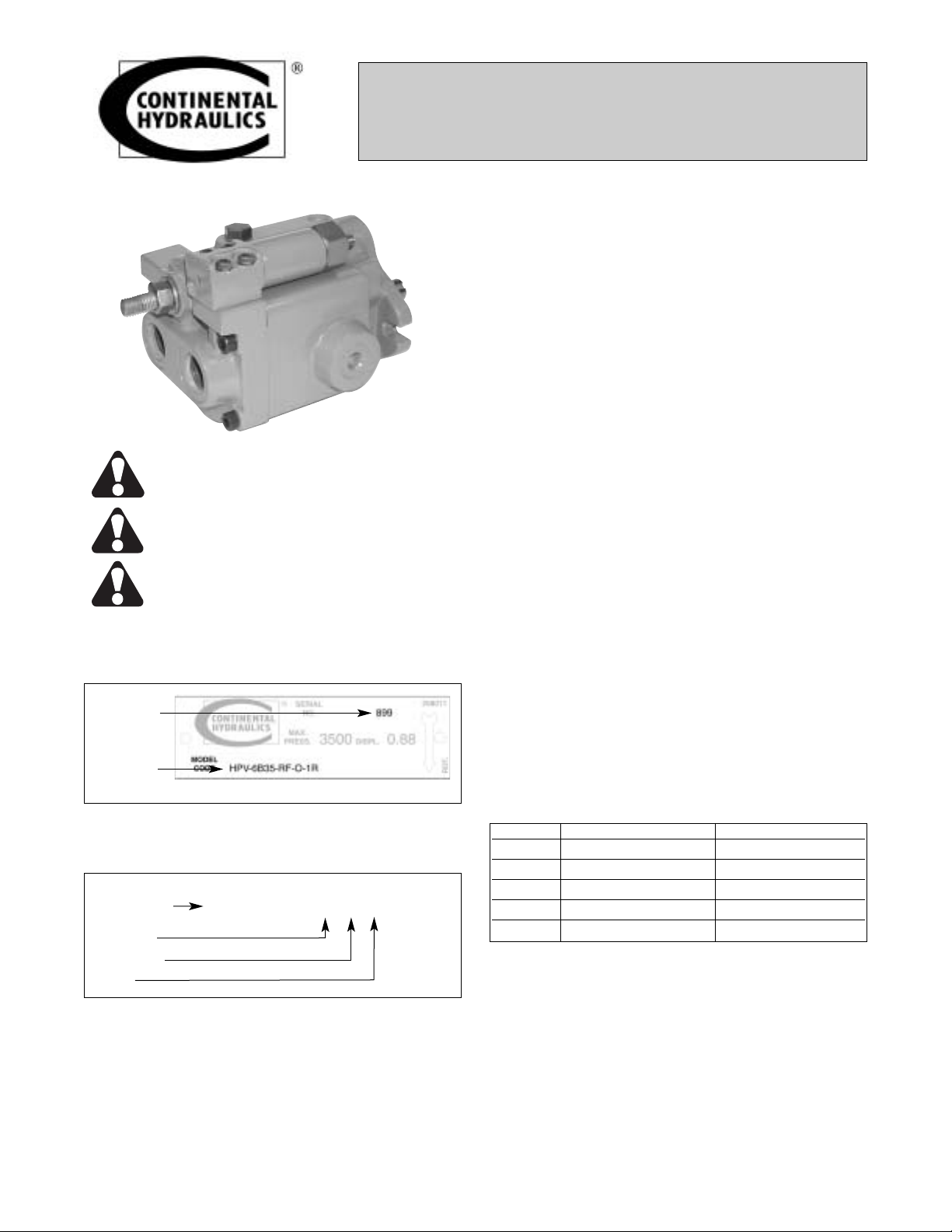
SERVICE MANUAL
HPV Axial Piston Pumps
“B” Design Series
GENERAL SPECIFICATIONS
MOUNTING
Any unrestricted mounting position acceptable.
Horizontal mounting preferred. The mounting hub
and two-bolt mounting flange conform to SAE
mounting standards.
Continental Hydraulics does not recommend direct
rigid connection of piston pumps to the Prime Mover.
Use of a flexible coupling, a coupling that allows for
minor misalignment is recommended.
If the shaft connection to the Prime Mover is rigid, the
mounting face diametric concentricity and squareness
must be within .001 inch (0.03 mm) T.I.R. for a flange
mounted pump.
The HPV Piston Pump is designed for in-line drive.
Angle drive creates side loads on the shaft, and is not
acceptable.
SHAFT INFORMATION
Splined:
The coupling interface must be lubricated.
Continental Hydraulics recommends lithium
molydisulfate, or similar grease. The female coupling
should be hardened to 27-45 Rc, and must conform
to ANSI B92.1 Class 5 Fillet or Flat Root Side Fit.
Keyed:
High strength heat treated keys must be used.
Replacement keys must be hardened to 27-34 Rc.
Key corners must be chamfered .030 - .040 inch (.75
- 1.0 mm) at 45° to clear radii in the keyway.
PLUMBING
Connect inlet and outlet lines to the pump’s cover.
HPV fluid connections are SAE straight thread, SAE
flange or BSPP.
MODEL REAR PORT SIDE PORT
HPV-6 SAE-12 or 3/4” BSPP SAE-16 or 1” BSPP
HPV-10 SAE-20 or 1-1/4” BSPP SAE-20 or 1-1/4” BSPP
HPV-15 SAE-20 or 1-1/4” BSPP SAE-20 or 1-1/4” BSPP
HPV-20 SAE-20 or 1-1/4” BSPP SAE1-1/4” Flange*
HPV-29 SAE-20 or 1-1/4” BSPP SAE1-1/2” Flange**
* Per Code 62 ** Per Code 61
Maximum case pressure is 10 psi (0.70 bar). Case
pressure must never exceed inlet pressure by more
than 15 psi (1.0 bar). To prevent fluid drain-down
from the pump when idle, make certain that case
drain plumbing passes above the highest point of the
pump before entering the reservoir. Or, install a 5 psi
(.3 bar) case pressure check valve to assure that the
pump is always filled with hydraulic fluid.
The case drain line must be big enough to prevent
back pressure in excess of 10 psi (0.70 bar).
Form No. R92.00 Rev. 10/03
1
Page 2
PLUMBING (continued...)
Hydraulic fluid from the case drain line should be
returned to the reservoir below the fluid level, and as
far from the supply intake as possible. All fluid lines
(whether pipe, tubing or hose) must be of adequate
size and strength to assure free flow through the
pump. Do not tee return lines together.
SYSTEM RELIEF VALVES
Although HPV series pumps have a very fast offstroke compensator response, fast acting relief valves
are recommended in all cases for safety. They also
help reduce transient pressure spikes.
RECOMMENDED FLUID
Note: The following fluid recommendations
and specifications apply to HPV series
pumps only. Assure that all other
components in the hydraulic system have
compatible requirements.
Petroleum-based, and most phosphate esters. Fluids
should be designated by the manufacturer for use in
hydraulic systems. Fluids should be formulated with
oxidation inhibitors, anti-rust, anti-foam and
deaerating agents. Other fluids may be acceptable,
but special O-rings may be required. Nitrile (Buna)
seals are standard.
VISCOSITY
Maximum at full power . . . . . . .750 SUS (160 Cst)
Optimum for maximum life . . . .140 SUS (30 Cst)
Minimum at full power . . . . . . . 60 SUS (10 Cst)
VISCOSITY INDEX
90 V.I. minimum. Higher values extend the operating
temperature range, but may reduce fluid service life.
Fluid Operating Temperature – Operating
temperature should be determined by the viscosity
characteristics of the fluid used. Fluid temperature in
the reservoir during operation should be kept between
100° F. and 130° F. (38° C. and 54° C.) Because high
temperature degrades seals, reduces service life and
creates hazards, fluid temperature should not exceed
180° F. (82° C.) at the case drain.
CAUTION – Fluid temperatures in excess of
120° F. (49° C.) can cause serious burns and
scalding. Allow fluid to cool before
performing any repairs or maintenance.
Fluid Cleanliness – Control particle contamination by
changing or cleaning all filter elements periodically
BEFORE they become clogged and start to by-pass.
Fluid must be cleaned before and continuously during
operation to a cleanliness level of ISO 18/16/13 or
better. This level of cleanliness can usually be
accomplished by use of 10 micron filters. Better fluid
cleanliness will significantly extend component life.
Since contaminant generation varies with each
application, each must be analyzed to determine
proper filtration to maintain required cleanliness.
After Extended Shutdowns – Some types of
hydraulic fluids become tacky after long periods of
non-use. If possible, hand turn the pump several
times after extended shutdowns to assure that all
components move freely before powering up.
CAUTION – Before hand turning any pump,
be sure that any resulting machine function
will not endanger persons or equipment.
PREVENTIVE MAINTENANCE
This pump is self-lubricating. Preventive maintenance
is limited to keeping the system fluid clean by
changing filters regularly. Since filtering needs can
vary depending on applications, filters used with this
pump should be equipped with indicators that show
when changes are needed. Do not operate the pump
in a system with clogged or bypassing filters.
Keep all fittings and screws tight. Do not operate this
pump at pressures or speeds in excess of stated
limits. If the pump does not operate properly, check
the Trouble Shooting Section of this manual before
attempting to overhaul the pump.
Overhauls are relatively simple, and are covered in
the Repair Procedures Section of this manual.
Note: It is especially important to keep
suction or inlet piping and fittings tight
and in good repair. Air drawn into the
system through loose or damaged intake
fittings can cause the pump to fail.
START UP PROCEDURE FOR NEW INSTALLATION
1. Read and understand the Service Manual. Identify
components and their
functions.
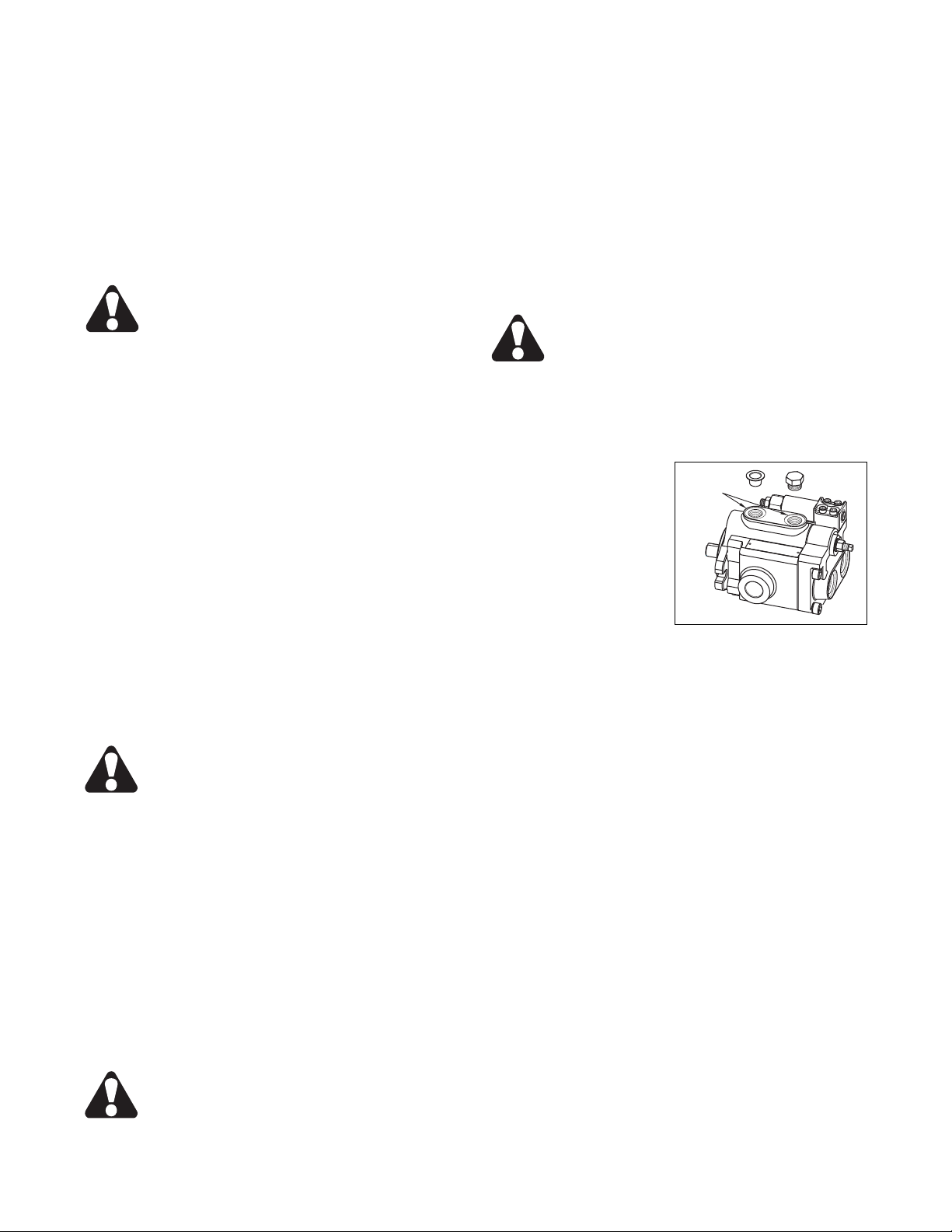
2. Visually inspect system
Case Drain
Ports
components and lines for
possible damage.
3. Check reservoir for
cleanliness. Drain and
clean as required.
4. Check reservoir fluid
level and fill as required
with filtered fluid that
Figure 3
meets or exceeds ISO 18/16/13 cleanliness level. Fill
pump through either Case Drain Port (Figure 3).
5. Check drive alignment.
6. Check and activate oil cooler (if included in circuit).
Check fluid temperature.
7. Reduce relief valve pressure settings. Make sure
accurate pressure readings can be made at
appropriate places.
8. If the system includes solenoids, check for proper
actuation.
9. Jog electric motor to confirm proper rotation.
Jogging the electric motor primes the pump and
bleeds air from the system.
10. Start pump drive. Look for leaks, and listen for
excessive noise at the pump. If leaks, chattering or
other noises are observed, immediately turn the pump
off. Corrective actions are covered in the Trouble
Shooting Section.
11. Cycle unloaded machine at low pressure, and
observe actuation (at low speed, if possible).
12. Increase pressure settings gradually. Check for
leaks in all lines, especially in the pump inlet line.
13. Adjust system pressure as needed.
14. Gradually increase system speed to normal
operating level. Be alert for trouble as indicated by
noise, sound changes, system shocks, leaks, or air
bubbles in the reservoir.
2
Form No. R92.00 Rev. 10/03
Page 3
START UP PROCEDURE (continued...)
15. When the system is running normally, check fluid
level and temperature at the reservoir. Repeat these
checks periodically. Excessive fluid temperatures will
damage the pump. If fluid temperature does not
stabilize at 140° F (60° C.) or less, stop the system
and take appropriate corrective action.
16. System is operational. Follow appropriate
maintenance procedures to assure fluid cleanliness
and proper operating temperature.
REPLACEMENT PUMP INSTALLATION
To prevent premature pump failure, make
sure that the entire hydraulic circuit is
flushed completely clean before
installing and operating a replacement
pump.
Simply draining the reservoir or relying on the
system’s filters is not enough to adequately clean the
fluid. Debris trapped in other components or lines
may damage the components themselves, or be
drawn into the pump. Failure to properly flush the
system before installing a replacement pump voids
the pump’s warranty.
The following procedures checklist will help you
replace a hydraulic pump with confidence that it will
provide satisfactory pump life.
1. Determine the cause of the failure (be sure you
have found the cause, and not simply a symptom).
2. Eliminate the cause of the failure.
3. Drain the entire circuit, including cylinders, motors,
reservoirs, control valves, heat exchangers, and
filters.
4. Remove system lines and components. Flush with
a compatible solvent, or clean filtered oil to remove
contamination that may have entered the system
when the pump failed. Be certain that fluid has been
flushed from cylinders.
5. Visually inspect components for possible
contamination, and for proper operation. Pay special
attention to wipers on cylinder rods. Be sure that the
rods are free of nicks and scratches.
6. Flush the reservoir using pressurized solvent. Use
clean, dry, lint-free cloths to ensure a clean interior.
Inspect the filler/breather (if used) and the suction
strainer for cleanliness.
7. Install a new filter with a 10 micron or better
element, and low Beta ratio. If the machine does not
have a filter, install one that meets these
specifications.
8. Fill the reservoir with new, FILTERED oil of the
recommended type. Be certain to monitor the fluid
level, since the entire system (not just the reservoir)
must be filled.
9. Re-install all system lines. Visually inspect to make
sure they are clean, and free of contamination. Be
sure that all inlet fittings are tight and clean.
10. Install the new pump.
11. Follow the start-up procedures given on pages 2
and 3 of this manual.
12. Cycle all cylinders and operate all motors at
normal operating speeds for 20 minutes. While
operating, observe the reservoir fluid level, since all
components will be filling with hydraulic fluid.
13. Replace the filter element, and check the fluid
level. Add new, clean, filtered oil if required.
To assure that your replacement pump performs at
the same level as the original pump, check daily for
proper fluid level, filter condition and leaks. Change
fluid at recommended intervals. Good fluid
maintenance is especially important when using other
than mineral based fluids.
TROUBLESHOOTING GUIDE
Component problems and circuit problems are often
interrelated. Apoorly designed circuit may operate
with apparent success, but cause a component of the
not the cause of the problem. The following general
guide is offered to help you locate and eliminate the
cause of problems by studying their effects.
system to fail. The component failure is the effect,
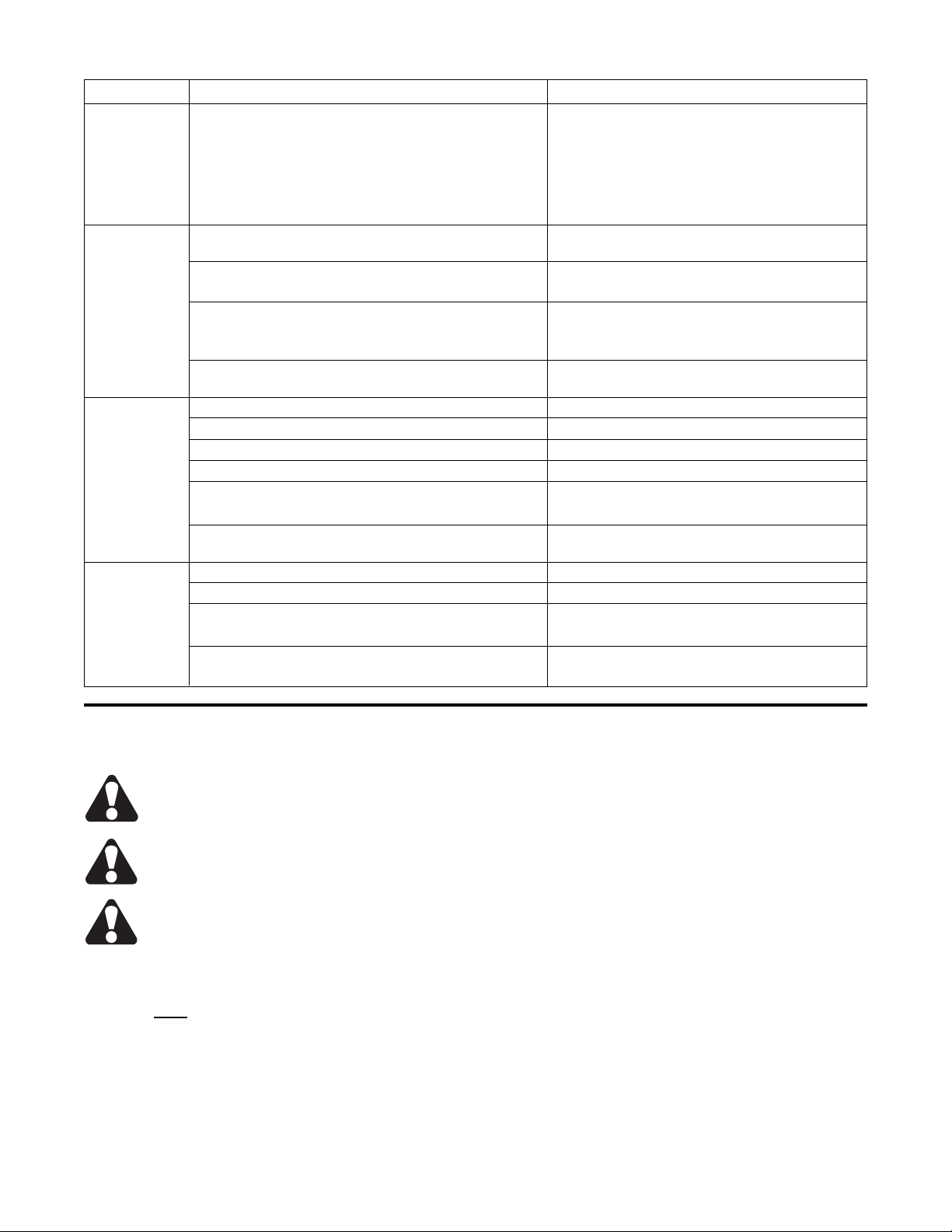
Problem Possible Cause Look For
Noisy Pump Air in fluid Leak in suction line
Leak in shaft seal
Low fluid level
Turbulent fluid
Return lines above fluid level
Gas leak from accumulator
Excessive pressure drop in the inlet line
from a pressurized reservoir
Cavitation in pump rotating group Fluid too cold, too viscous or too heavy
Shaft speed too high
Suction line too small, or collapsed
Suction line strainer dirty or too small
Form No. R92.00 Rev. 10/03
Continued on Page 4
3
Page 4
TROUBLESHOOTING GUIDE
Problem Possible Cause Look For
Noisy Pump Misaligned shaft Faulty installation
Distortion in mounting
Axial interference
Faulty coupling
Mechanical fault in pump Piston and shoe loose or failed
Bearing failure
Incorrect port plate selection or index
Eroded or worn parts in
displacement control
Erosion on Air in fluid Refer to above
barrel
and
Cavitation Refer to above
port plate
High wear Excessive loads Reduce speed or pressure setting
in pump
Contaminant particles in fluid Improper filter maintenance
Filter too coarse
Dirty fluid introduced to the system
Reservoir or breather cap open to
atmosphere
Improper line replacement
Improper fluid Fluid too thick or too thin for operating
temperature range
Fluid breakdown due to age, temperature
or shearing effects
Incorrect additives in new fluid
Reduced additive effectiveness due to
chemical aging
Improper repair Incorrect parts, procedures, dimensions
or finishes
Unwanted water in fluid Condensation
Faulty breather/strainer
Heat exchanger leaking
Faulty clean-up practice
Water in makeup fluid
Pressure Cogging or erratic load movement Mechanical considerations
shocks
Slow acting relief valve Replace with fast acting relief valve
Worn relief valve Repair or replace, as needed
Worn compensator Repair or replace, as needed
Insufficient line capacitance (line volume, Increase line size or length
line stretch, accumulator effects)
Fluid Excessive pump leakage Recheck case drain flow,
overheats repair as needed
Fluid too thin, minimum operating viscosity
60 SUS (10Cst)
Improper assembly
Faulty relief valve Set too low (compared to load
or compensator)
Instability caused by back pressure,
or worn parts
Faulty compensator Set too high (compared to relief)
Worn parts
Faulty heat exchanger Water turned off, or insufficient flow
Ambient water temperature too high
Fan clogged, restricted or inoperative
Mud or scale buildup
Intermittent hydraulic fluid flow through
exchanger
Continued on Page 5
4
Form No. R92.00 Rev. 10/03
Page 5
TROUBLESHOOTING GUIDE (continued)
Problem Possible Cause Look For
Fluid Faulty reservoir Fluid level too low
overheats
(continued)
Entrained air in fluid
Improper, or no baffles
Poor air flow, or ambient air temperature
too high around reservoir
Heat pick up from adjacent equipment
Decrease in Loose compensator adjusting screw Tighten adjusting screw ( No.11 in
set pressure Fig. 14, exploded view)
Defective function or relief valves Repair or replace relief valve
Check relief valve setting
Reservoir fluid level too low Replenish fluid
Check drain (below 5% of discharge at
rated pressure)
Deteriorating pump performance Check pump internal components for wear,
repair or replace as needed.
Pressure Pump turning backward Change the rotating direction
does not rise
Reservoir fluid level too low Replenish fluid
Relief valve or compensator set wrong Readjust and lock
Relief valve or compensator defective Repair or replace
Clogged suction line Inspect and clean suction strainers
Open gate valve
Deteriorating pump performance Check pump internal components for wear,
repair or replace as needed.
Insufficient Reservoir fluid level too low Replenish fluid
flow
Suction line not sealed Tighten fittings
Improper pump stroke control adjustment Readjust as required
Repair or replace as required
Deteriorating pump performance Change compensator
Worn compensator
PISTON PUMP DISASSEMBLY
Precautions
CAUTION – Before performing any service
operation on any pump, be sure that all
pressure has been relieved from BOTH
SIDES of the system.
CAUTION – Before performing any service
operation on any pump, disconnect or lock
off power supply.
CAUTION – Do not attempt to remove the
Barrel Spring. The Barrel Spring is
assembled under high compression. Any
attempt to remove the Barrel Spring will
cause sudden decompression, and may inflict serious
personal injury. The Barrel Spring is NOT field
serviceable. Should the Barrel Spring require service,
the pump must be returned to Continental Hydraulics
or an Authorized Repair Center.
1. Please refer to the exploded view (Figure 14
through 17) for proper names and locations of all
parts.
Form No. R92.00 Rev. 10/03
2. Pump disassembly for inspection and repair should
be undertaken only in the following cases:
Malfunction or leakage due to damage or
wear.
When troubleshooting procedures contained
in this manual do not solve a problem.
3. Disassembly should be done only as far as
necessary to replace or repair worn parts.
4. Perform assembly and disassembly in a clean
environment.
5. Avoid dropping, damaging or contaminating the
machined parts of the pump and compensator.
6. After disassembly, coat the internal parts with a film
of clean oil, and protect them from dirt and moisture.
7. Prior to disassembly, measure and record the
length of the protruding part of adjusting screws (22)
and (28-11) from Figure 14, and if necessary, (18)
from Figure 16 or 17. This will simplify resetting the
pump after reassembly.
5
Page 6
HPV REPAIR PROCEDURES
DISASSEMBLY, INSPECTION and REASSEMBLY
GENERAL
Disassembly in the field by other than an Authorized
Repair Center technician, whether for repair or
modification will void warranty.
NOTE: Certain steps in this procedure
require special tools, and the application
of great force. Care should also be taken
to contain residual oil during
disassembly. Before beginning, read this section
through to make sure that you are prepared for
the job.
General Disassembly Procedure
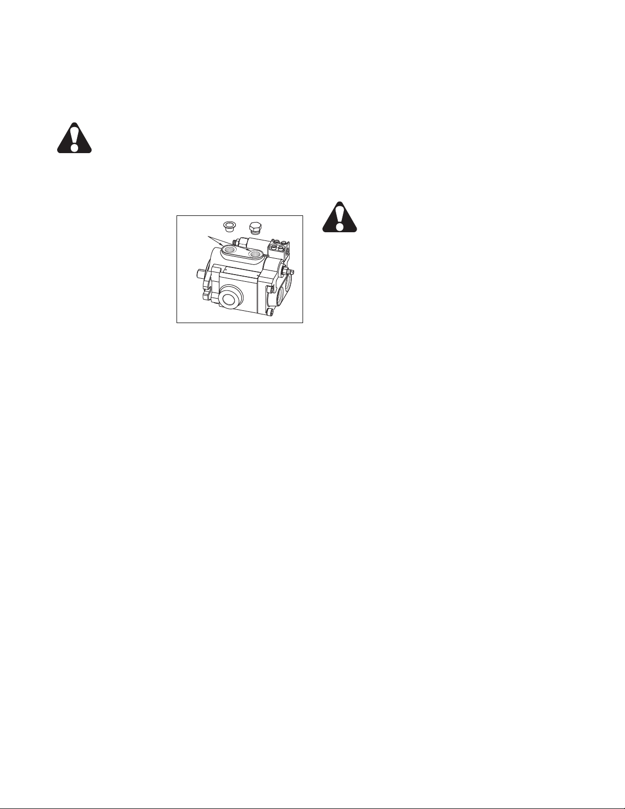
1. Drain pump body (1)
via Case Drain Ports.
(Figure 4)
2. Position the pump with
Case Drain Ports up.
3. Remove four
compensator screws (71)
and then remove remove
compensator (28) and Orings (32).
4. Remove four cover
retaining screws (46). Loosen two diagonally
positioned screws first. Then loosen the remaining
two diagonally positioned screws. Remove the
screws and carefully separate the cover (2) from the
pump body. If the gasket holds the cover in place, tap
the cover lightly with a fiber hammer on the side
opposite the compensator.
NOTE: The port plate (4) may cling to the cover (2)
due to oil film between parts. DO NOT ALLOW THE
PLATE TO FALL AND BE DAMAGED.
5. Gently remove the port plate (4) from the barrel (3)
face.
6. Place the pump on a work bench with the shaft in a
horizontal position. Remove the barrel (3) with piston
assembly (5), guide ball (14), guide plate (15), and
dowel pins (56) as a unit.
7. Place the barrel (3) on a clean cloth or plastic film.
Hold the side of the guide plate (15) and gently
remove the piston assembly.
8. Remove the guide ball (14) and dowel pins (56).
9. Place the pump body (1), shaft down, on a fixture
designed to keep it from toppling. Protect with a dustproof plastic film.
10. Place the cover (2) with the assembled guide
sleeve (64), plunger (21) and needle bearing (65) on
a work bench. The guide sleeve must face up.
Protect the parts with a dust-proof plastic film.
NOTE: Following completion of disassembly
procedure steps 1 through 10, necessary pump
inspection can be performed. Further disassembly
may be required if the following inspection steps
reveal specific problems.
11-1. When the barrel (3) is laid flat, the dowel pins
(56) must protrude slightly. If otherwise, or if the
dowel pins are easily pushed in, replace the barrel.
Case Drain
Ports
Figure 4
11-2. If the hanger (9) has little or no inclination
against the shaft (8), or if it can easily be moved by
hand, go to steps 12 through 15.
11-3. If shaft seal leakage or excessive ball-bearing
play is apparent, go to steps 16 through 21.
11-4. If compensator function is erratic, go to steps 23
through 33, as required.
Hanger Removal
12. Place the pump body in a large vise, or on a
working surface adapted to hold the pump body firmly.
13. Remove the trunnions (10) using the blind
threaded holes, and the appropriate trunnion removal
tool. See Figure 9 on page 13 for trunnion removal
tool specifications.
CAUTION: The hanger may be under
tension, and should be secured to
prevent injury.
14. Remove the hanger (9), spring seat (20), and
spring (19) in this order.
15. Proceed to HANGER INSPECTION and
TRUNNION INSPECTION, page 9.
Shaft Removal and Disassembly
16. As required, remove the key (70). Tap gently at
the end of the key with a hammer or chisel if it is
difficult to remove.
17. Remove the retaining ring (41) with a snap ring
pliers.
18. Remove the shaft (8). Pull the shaft toward the
cover. Tap lightly with a fiber hammer on the end of
the shaft if it is difficult to remove.
19. Replace the ball-bearing if it shows excessive
wear, or if noise is heard when rotating the outer race
by hand.
20. To replace the ball bearing, remove retaining rings
(68), and remove the ball bearing (69) with a hand
press or by light hammering.
21. If oil leaks are observed, the shaft seal must be
replaced. Remove the shaft seal (38) from the pump
body (1). Use a push rod of smaller diameter than
the outside diameter of the shaft seal.
NOTE: Do not reuse seals. See Parts List, page 17,
Item 38 for replacement part numbers.
22. Proceed to SHAFT INSPECTION, page 9, and
BALL BEARING INSPECTION, page 11.
Compensator Disassembly
23. Loosen the hex nut (28-12) and remove the
adjusting screw (28-11) from the end cap (28-3).
24. Remove the end cap (28-3).
25. Remove the spring (28-6) and spring seat (28-5).
26. Remove the spool (28-2).
Continue for Codes 7, 19, and 26 compensators.
Item numbers refer to figures 16 and 17, page 20.
27. Loosen the hex nut (12) and remove the adjusting
screw (18) from the body (1).
28. Remove the spring (7) and cone (16).
29. Proceed to PRESSURE COMPENSATOR
INSPECTION, page 11.
6
Form No. R92.00 Rev. 10/03
Page 7
HPV REPAIR PROCEDURES (continued)
NOTE: If the cone is badly worn or damaged, perform
the following steps.
30. For Code 7 or 19 compensators, remove the plug
(20). Using a rod, tap the seat (15) out from the
opposite end.
31. For Code 26 compensators, remove the fitting
(27) and adjusting screw (18) as an assembly.
32. Remove the dowel pin (24) and ball (17).
33. Remove the fitting (29). Using a rod, tap the seat
(15) out from the opposite end.
Rework Limits for Wear Parts
Barrel Bores − Measure each bore in four places,
including one place deep within the bore, where the
piston doesn’t run. Replace the barrel if the
difference in measurements exceeds .0004 in. or .010
mm.
Barrel Face − May be lapped no more than .0002 in.
or .005 mm measured by before and after depths of
oil grooves on barrel face.
Pistons (5) − Measure each piston in four places,
including one at the shoe end, where the piston
doesn’t enter the barrel. Replace Piston if the
difference in measurements exceeds .0006 in. or .015
mm.
Shoe, Piston Assembly − Replace assemblies if end
play exceeds .003 in. or .076 mm.
Shoe, Face − May be lapped up to .004 in. or .102
mm. The difference in shoe flange thickness
between the thinnest and thickest of nine shoes
should not exceed .0012 in. or. 03 mm.
Port Plate (4) − May be lapped .006 in. or .152 mm.
Maintain flatness of .0002 in. or .005 mm.
Wear Plate (16) − Do not lap. Replace if there are
any indications of wear or bending.
Guide Plate (15) − Do not lap. Measure thickness at
several places. Replace if thickness varies more than
.004 in. or .102 mm.
INSPECTION PROCEDURES
Part (Item No.) Inspection Procedure Corrective Action
Check for cracks around tapped holes.
Pump Body Check for cracks around retainer ring groove. Replace if cracked.
(1) Perform dye penetrant or magnetic particle inspection over
entire housing when oil leakage is observed.
Visually inspect for obvious defects
Check for excessive wear in guide sleeve (64). Axial scratches
should not be detectable with a fingernail. Diameter difference
Cover must not exceed .001 in. or .025 mm when measured at several Replace if defective
(2) random points.
Check for excessive play between drive shaft (8) and needle
bearing (65). (Maximum radial play is .003 in. or .076 mm.)
Repair by lapping until
Visually inspect the barrel face for uniform minute concentric nicks. scratches are removed.
Do not exceed rework
limits listed above.
Visually inspect for deep, localized nicks. Replace barrel. Flush
Barrel reservoir and circuit.
(3) Replace barrel.
Check for
Visually inspect for signs of seizure, scoring or discoloration. correct hydraulic fluid
type, temperature rise,
excessive pressure.
Correct as needed.
Form No. R92.00 Rev. 10/03
Continued on Page 8
7
Page 8

INSPECTION PROCEDURES Continued
Part (Item No.) Inspection Procedure Corrective Action
Barrel Visually inspect the bores’ internal condition for the following
(3) A. Localized polishing at edge. A. Re-use as is.
(Continued) B. Minute, longitudinal nicks. B. Re-use as is.
C. Localized longitudinal nicks. C. Replace part.
Flush reservoir
and circuit.
D. Localized seizure, scoring, discoloration D. Replace barrel and
all piston and
shoe assemblies (5).
Check for correct
hydraulic fluid type,
temperature rise,
excessive pressure.
Correct as needed.
Inspect for bore wear as follows. Wash the barrel bore. Insert a If no resistance,
piston completely into a bore. Cover the kidney-shaped hole replace the barrel
in the barrel, and the center hole on the shoe. Withdraw and piston assemblies.
the piston. If there is resistance
the bore is reusable.
Measure each bore in four places, including one place deep Replace the barrel if the
within the bore, where the piston doesn’t run. difference in
measurements
exceeds .0004 in.
or .010 mm.
Port Plate Visually inspect the surface for uniform minute concentric Repair by lapping
(4) scratches, or deep scratches on the plate. until scratch is
removed. Do not
remove more than
.006 in. or .152 mm.
Maintain flatness
of .0002 in. or .005 mm.
Visually inspect for heat discoloration Use as is. Lap if
excessively discolored.
Do not remove more
than .006 in. or .152 mm
Inspect for cavitation erosion between ports Repair by lapping
until erosion is
removed. Do not
remove more than
.006 in. or .152 mm.
Piston Inspect for shoe end play by pushing and pulling the shoe while Replace piston
Assembly holding the piston. If the shoe clicks, or if movement can be assemblies as a set.
(5) seen, the piston assembly is excessively worn. Check circuit suction
pressure. If less than
-5 in. Hg., raise fluid level
in reservoir, clean intake
strainer and/or correct
faulty circuit design.
Visually inspect shoe face for localized polishing, or random Repair by lapping
radial marks. assemblies as a set.
Shoes may be lapped
up to .004 in. or .102 mm.
Difference in shoe flange
thickness between the
thinnest and thickest of
nine shoes should not
exceed .0012 in.
or .03 mm.
Check circuit suction
pressure. If less than
-5 in. Hg., raise fluid level
in reservoir, clean intake
strainer and/or correct
faulty circuit design.
8
Form No. R92.00 Rev. 10/03
Continued on Page 9
Page 9

INSPECTION PROCEDURES (Continued)
Part (Item No.) Inspection Procedure Corrective Action
Piston Visually inspect the shoe flange for burrs or rolled edges If slight, repair by lapping.
Assembly If severe, replace part.
(5)
(Continued) Inspect the piston outer diameter. Measure each piston in four Replace Piston if the
places, including one at the shoe end, where the piston doesn’t difference in
enter the barrel. measurements exceeds
.0006 in. or .015 mm.
Visually inspect for slight discoloration or cross hatch trace. Reuse as is.
Visually inspect for localized scratch marks running in Replace pistons
a longitudinal direction. as a set. Flush
reservoir and circuit.
Visually inspect for signs of seizure, scoring or discoloration Replace piston and
shoe assemblies (5).
Replace barrel (3).
Check for correct
hydraulic fluid type,
temperature rise,
excessive pressure.
Correct as needed.
Shaft Visually inspect the shaft end outer surface.
(8) A. If burnt brown spots are apparent over entire surface A. Remove with
emery paper.
B. If uneven wear on key side surface B. Check fit to coupling
hub. If loose, replace.
Inspect for pitting or corrosion over all or part of shaft surface. Replace shaft.
Check fit to coupling hub
Check alignment between
prime mover and pump.
Correct as needed.
Visually inspect shaft seal surface for:
A. Seal contact marks. A. Use as is.
B. Bright polish B. Use as is.
C. Contact marks over 0.04 in. or 1 mm wide, can be felt with C. Replace shaft.
fingernail. Inspect and replace
shaft seal as needed.
Visually inspect key groove bottom end for cracks. If in doubt, If cracked, replace shaft.
check with dye penetrant or magnetic particle inspection. Check alignment with
prime mover. Correct
as needed.
Inspect needle bearing rolling contact surfaces for wear. Replace shaft if difference
between bearing contact
and non-contact surfaces
is more than .0008 in.
or .020 mm
Hanger Visually inspect the trunnion bore.
(9) Contact surface not excessively worn Reuse hanger as is.
Contact surface shows obvious wear, uneven contact or Replace the hanger
localized nicks. when inside diameter
difference is directionally
more than .0008 in.
or .020 mm.
Visually inspect contact surface with the plunger (21).
Wear marks up to 0.2 in. or 5 mm wide. Reuse hanger as is.
Wear marks over 0.2 in. or 5 mm wide. Replace hanger.
Adjust volume as needed.
Trunnion Visually inspect contact surface to hanger (9).
(10) Very slight wear. Reuse trunnion as is.
Localized seizure, scoring, discoloration. Replace the trunnion.
Also replace hanger (9).
Check hydraulic fluid
type, temperature rise,
excessive pressure.
Form No. R92.00 Rev. 10/03
Continued on Page 10
9
Page 10

INSPECTION PROCEDURES (Continued)
Part (Item No.) Inspection Procedure Corrective Action
Key Inspect for wear on side surface.
(70) A. Discoloration. A. Remove discoloration
with emery cloth.
Reuse key.
B. Stepped wear. B. Replace key if worn
over .0002 in. or
.005 mm. When
coupling hub-to-shaft fit
is loose, replace the
coupling. Recheck
alignment with prime mover.
Check for excessive
pressure or side load.
Correct as needed
Guide Plate Visually inspect contact surface between guide plate Re-use as is.
(15) and piston shoe. If brightly polished,
Inspect contact surface for indentations. If stepped or indented, Replace guide plate.
Wear Plate Check face condition for:
(16) A. Polish over all or part of the surface A. Re-use as is.
B. Scratches, wear or metal transfer B. Replace wear plate.
Flush reservoir
and circuit.
Check hydraulic fluid
type, temperature rise,
and excessive pressure.
Correct as needed.
Spring Measure free heights. Correct heights are:
(18) A. HPV-6: 1.36” or 34.5 mm Replace when height
B HPV-10: 1.57” or 40 mm is decreased more
C. HPV-15: 1.79” or 45.5 mm than 5% from the
D. HPV-20: 1.97” or 50 mm given heights.
E. HPV-29: 2.05” or 52 mm
Spring Measure free height. Correct heights are:
(19) A. HPV-6: 2.44” or 62 mm Replace when height
B HPV-10: 2.60” or 66 mm is decreased more
C. HPV-15: 3.00” or 76 mm than 3% from the
D. HPV-20: 3.00” or 76 mm given heights.
E. HPV-29: 3.19” or 81 mm
Plunger Inspect contact pattern on spherical surface.
(21) A. Wear pattern less than 0.2 in. or 5 mm wide A. Re-use as is.
B. Wear pattern over 0.2 in. or 5 mm wide B. Replace plunger.
In case of rapid wear,
check hydraulic fluid
type, temperature rise,
and excessive pressure.
Correct as needed.
Guide Sleeve Inspect outer surface contact condition.
(64) A. Slight uneven wear on one side, partial polishing. A. Re-use as is.
B. Distinct localized contact, with strong, bright polishing. B. Replace guide sleeve
and cover (2).
Measure guide sleeve outside diameter at several points. If the difference is more
than .0008 in. or .020 mm
replace guide sleeve and
cover (2). Check
fluid type, temperature
rise, and pressure.
Correct as needed.
Visually inspect for signs of seizure, scoring, or discoloration. Replace guide sleeve
and cover (2).
Check hydraulic fluid
type, temperature rise,
and excessive pressure.
Correct as needed.
10
Form No. R92.00 Rev. 10/03
Continued on Page 11
Page 11

INSPECTION PROCEDURES (Continued)
Part (Item No.) Inspection Procedure Corrective Action
Ball Bearing Inspect for radial play or sticking. Replace ball bearing if
(69) Rotate outer race by hand. excessive play or sticking
is felt, or if unusual
noise is heard.
Replace if obvious
discoloration or pitting
are observed.
Needle Visually inspect rolling surfaces. Replace if obvious
Bearing discoloration or pitting
(65) are observed.
Gasket Replace whenever pump
(24) is disassembled.
Shaft Seal Replace whenever shaft
(38) is removed from pump.
Thread Seal Visually inspect for damage. Replace thread seal
(54) as needed.
ASSEMBLY TOOLS
Shaft Seal Installation Tool
Series A* B C† DE F
HPV-6
HPV-10
HPV-15
HPV-20
HPV-29
In. 1.75 2.17 .185 5.0 1.25 .79
(mm) (44.5) (55.1) (4.7) (127) (31.75) (20.1)
In. 1.75 2.17 .185 5.0 1.25 .79
(mm) (44.5) (55.1) (4.7) (127) (31.75) (20.1)
In. 1.95 2.36 .197 5.0 1.25 .79
(mm) (49.5) (59.9) (5.0) (127) (31.75) (20.1)
In. 2.15 2.56 .204 5.0 1.25 .79
(mm) (54.6) (65.0) (5.2) (127) (31.75) (20.1)
In. 2.15 2.56 .204 5.0 1.25 .79
(mm) (54.6) (65.0) (5.2) (127) (31.75) (20.1)
Material: Steel
* ± .008 in. (± .203 mm)
† +.0 in. (+.0mm)
-.008 in.(-.203 mm)
Figure 5 (not to scale)
Form No. R92.00 Rev. 10/03
11
Page 12

ASSEMBLY TOOLS (continued)
Ball Bearing Installation Tool
Series A B* C D
HPV-6
HPV-10
HPV-15
HPV-20
HPV-29
In. 2.36 2.08 1.02 4.33
(mm) (59.9) (52.8) (25.9) (110)
In. 2.76 2.44 1.02 4.52
(mm) (70.1) (62.0) (25.9) (114.8)
In. 3.15 2.83 1.22 5.19
(mm) (80.0) (71.9) (31.0) (131.8)
In. 3.54 3.15 1.42 6.30
(mm) (89.9) (80.0) (36.0) (160.0)
In. 3.54 3.15 1.42 6.30
(mm) (89.9) (80.0) (36.0) (160.0)
Material: Steel
* +.012 in. (+.305 mm)
-.004 in.(-.102 mm)
Figure 6 (not to scale)
Protective Cone
Series A* B† CDE
HPV-6
HPV-10
HPV-15
HPV-20
HPV-29
In. 1.00 0.75 2.24 1.65 1.57
(mm) (25.4) (19.1) (56.9) (41.9) (39.9)
In. 1.00 0.875 2.68 2.08 2.00
(mm) (25.4) (22.2) (68.1) (52.8) (50.8)
In. 1.20 0.875 2.68 2.08 2.00
(mm) (30.5) (22.2) (68.1) (52.8) (50.8)
In. 1.40 1.25 2.68 2.08 2.00
(mm) (35.6) (31.8) (68.1) (52.8) (50.8)
In. 1.40 1.25 2.68 2.08 2.00
(mm) (35.6) (31.8) (68.1) (52.8) (50.8)
Material:Teflon preferred, or steel heat treated to
Rc40 or Rc45, and chromium plated.
*± .004 in. (± .102 mm)
† +.008 in. (+.203 mm)
-.004 in.(-.102 mm)
Trunnion Assembly Tool
Series A B C
HPV-6
HPV-10
HPV-15
HPV-20
HPV-29
In. 1.75 .997/.996
(mm) (44.45) (25.32/25.30)
In. 1.75 .997/.996
(mm) (44.45) (25.32/25.30)
In. 2.00 1.247/1.246
(mm) (50.80) (31.67/31.65)
In. 2.25 1.497/1.496
(mm) (57.15) (38.02/38.00)
In. 2.25 1.497/1.496
(mm) (57.15) (38.02/38.00)
1/2-13 UNC X 3/4 DP
1/2-13 UNC X 3/4 DP
3/4-10 UNC X 1 DP
3/4-10 UNC X 1 DP
3/4-10 UNC X 1 DP
Material: Steel, or rework trunnion to B diameter.
12
Form No. R92.00 Rev. 10/03
(3.0 to 5.0 mm)
Figure 7 (not to scale)
Figure 8 (not to scale)
Page 13

ASSEMBLY TOOLS (continued)
Trunnion Removal Tool
Series A B C D E F
DIA. DIA. THD. DIA.
HPV-6 In. 1.75 1.50 .56 4.25
HPV-10 (mm) (44.5) (38.1) (14.2) (108) (63.5)
HPV-15
HPV-20 In. 2.25 2.00 .81 4.75
HPV-29 (mm) (57.15) (50.8) (20.6) (121) (76.2)
In. 2.00 1.75 .81 4.50
(mm) (50.8) (44.5) (20.6) (114) (69.8)
1/2-13
3/4-10
3/4-10
2.50
2.75
3.00
Material:
Item . . . . . . . . . . . . . . . Material
(1) Sleeve . . . . . . . . . . Steel
(2) Spacer . . . . . . . . . . Steel
(3) Nut . . . . . . . . . . . . . Hardened Steel GR.5
(4) All-Thread Rod . . . . Hardened Steel GR.5
ASSEMBLY PROCEDURES
Figure 9 (not to scale)
Pump Assembly
Piston Pump assembly must be done more carefully
than disassembly. The working environment must be
clean. All parts must be clean and inspected for wear
or damage in accordance with the Inspection
Procedures listed on pages 7 through 11.
1. Compare the disassembled parts with the exploded
view shown in Fig. 14 or 15 on page 20 for missing
parts or irregularities.
2. Inspect retaining rings. Replace if deformed.
3. Place the pump body (1) in a press, with the
mounting flange facing up.
4. Apply grease between the lips of the shaft seal.
Grease should not protrude above the tip of the lip,
and should fill approximately 80% of the space.
5. Use a press, and the tool shown in Fig. 5 on page
11, slowly force the shaft seal into the pump body (1)
until seated.
6. Assemble a retaining ring (68) on the shaft end.
The sharp edge of the retaining ring must always be
facing away from the part being retained.
7. Using the ball bearing installation tool shown in Fig.
6 on page 12, press the ball bearing (69) onto the
shaft. Do not exceed the maximum pressing force
guidelines listed as follows.
8. Install the remaining retaining ring (68).
Pressing Force
Series Bearing Part No Lbs. N
HPV-6 258191 1330 5900
HPV10 258192 1500 6700
HPV10 258193 1690 7500
HPV10 258194 2200 9800
HPV10 258194 2200 9800
9. Rotate the bearing manually to check for unusual
noise or binding.
10. Fit the protective cone shown in Fig. 7 on page 12
over the end of the shaft. Apply a light coating of
lithium grease to the outer surface of the cone. Slide
the protective cone and shaft through the shaft seal,
positioning the ball bearing in place.
11. Assemble the retaining ring (41) into the pump
body.
12. Place the housing on a fixture with the shaft end
facing down. Insert the spring (19) and spring seat
(20) into the pump body.
13. Lightly coat the wear plate (16) with grease, and
mate to the hanger (9). Then fit into the pump body.
14. Press the hanger (9) until approximately
horizontal, using a press if necessary. Then install
the trunnions.
NOTE: A used trunnion shaft, turned
down to a slip fit simplifies hanger
installation. Slip the modified trunnion
into one side to hold it in place while the
working trunnion is press-fit into the opposite
side. See Fig. 8, page 12 for trunnion assembly
tool specifications.
15. Lightly coat the trunnions with teflon-based
sealing paste. Avoid putting sealing paste on the
section of the trunnion that will be held in the hanger.
Press them through the pump body, and into the
hanger.
NOTE: Be certain the hanger bores are
correctly aligned with the pump body.
After the trunnions have been installed,
confirm that the hanger moves freely on
them.
Form No. R92.00 Rev. 10/03
13
Page 14

PUMP ASSEMBLY (continued)
16. Place the barrel (3) on a clean working surface.
Insert the washers (27) and spring (18) into the center
hole. The washers (27) should be located on both
ends of the spring.
17. Compress the spring (18) using a mechanical
press. Secure the spring with the retaining ring (40).
18. Place the barrel (3) on a clean sheet of paper or
cloth. Insert the three dowels (56) into the holes
located outside of the spline hole. Place the guide
ball (14) on top.
19. Compress manually, and confirm spring(18) force.
20. Hold the guide plate (15) horizontal with one
hand, and insert the nine piston assemblies (5) into
the guide plate bores. The piston shoes should move
freely on the pistons.
21. Support the guide plate horizontally, and insert the
piston assemblies (5) into the barrel bores (3).
22. Place the pump body (1) so that the shaft (8) is
horizontal. Assemble the barrel (3), piston assemblies
(5), guide ball (14) and guide plate (15) together onto
the shaft.
CAUTION: Do not force the shaft spline
into the barrel groove. Carefully rotate
the parts, and apply slight pressure to
work them together. Assembly is correct
when the edge of the barrel is approximately .25
in. below the edge of the pump body.
23. Place the pump body (with shaft end pointing
down) on a fixture, and coat the face of the barrel with
clean hydraulic fluid. Place the gasket (24) on the
pump body.
24. Assemble the plunger (21) and port plate (4) onto
the cover (2).
25. Lightly coat the port plate (4) with grease. Place
the port plate on the cover (2), locating the “U”
shaped slot over the pin (66). See Fig. 10
Series N - m Lbs. - Ft.
Min. Max Min. Max
HPV-6 5.4 6.9 4.0 5.1
HPV-10 7.8 9.8 5.8 7.3
HPV-15 21.6 25.5 16.0 18.9
HPV-20 39.2 43.1 29.0 31.9
HPV-29 39.2 43.1 29.0 31.9
28. Attach rebuilt pressure compensator to pump
cover (2). Pressure compensator assembly
procedures are listed below, and on the next page.
29. Install the thread seal (54) and hex nut (45) on the
adjusting screw (22), then screw into the hole in the
pump cover (2). Finger tighten until the adjusting
screw bottoms against the plunger. Adjust to desired
volume.
Series No. of Turns Full to Zero Vol.
HPV-6 8.5
HPV-10 8.5
HPV-15 8.5
HPV-20 9.7
HPV-29 10.5
30. Using a lever or hub, rotate the shaft several
times in the direction indicated by the arrow on the
escutcheon plate (61). Confirm that the pump rotates
freely and smoothly.
31. With the palm of your hand, cover the port on the
side on which the compensator is mounted. Rotate
the input shaft. If air is forced out of the piping port,
the pump is working properly.
32. Screw the case drain plug (58) into the pump
body. Seal other openings with plastic cap seals.
33. Clean the outside of the pump, and re-install onto
the original equipment. If the pump will be stored
before re-installation, coat all unpainted surfaces with
a light coating of oil, and store in a sealed plastic bag.
Figure 10
26. Hold the cover so the plunger (21) does not fall
off. Then carefully place the cover on the pump body.
27. Secure the cover (2) with socket head screws
(46), tightened diagonally. The final tightening torque
should be as follows:
14
Form No. R92.00 Rev. 10/03
STANDARD PRESSURE COMPENSATOR
CONTROL (28) ASSEMBLY
1. Carefully clean the compensator body (28-1) and
spool (28-2). Soak in clean hydraulic fluid.
2. Check O-rings (28-8) and (28-9) for deformation or
wear. Replace as needed. Assemble O-ring (28-8) to
cap (28-3). Assemble O-ring (28-9) to spring seat
(28-4).
3. Carefully insert the spool (28-2) into the
compensator body (28-1).
4. Fit the spring seats (28-4) and (28-5) onto both
ends of the spring (28-6). Assemble into the
compensator body.
5. With the adjusting screw (28-11) and nut (28-12)
set on the cap, place the cap on the spring seat (28-
4), and screw into the threaded hole in the
compensator body. Tighten until the edge surface is
flush. Screw (28-11) adjustment rate
approximately 650 psi (45 bar) per turn.
Page 15

PUMP ASSEMBLY (continued)
6. Check O-rings (32) for deformation and wear.
Replace as needed. Install the O-rings.
REMOTE PRESSURE (Code 7), AND LOAD
SENSING CONTROL (Code 19) ASSEMBLY
See Figure 16
1. For initial assembly, follow steps 1 through 5 of the
Standard Pressure Compensator Assembly listed
above. For Load Sensing Control (Code 19) only,
install the pin (28-24) into the spool.
2. To install the seat (28-15), insert the open end into
the bore, and press into place. Install plug (28-20)
and tighten.
3. Fit the washer (28-23) and spring (28-7) onto the
adjusting screw (28-18). Fit the cone (28-16) into the
spring, and assemble into the body.
4. Set the adjusting screw to the measurement taken
at disassembly, and lock into place with nut (28-12).
Cover with acorn nut (28-22).
5. Install the O-rings (32). Assemble the compensator
to the pump cover.
HORSEPOWER LIMITING CONTROL (Code 26)
ASSEMBLY
See Figure 17
1. For initial assembly, follow steps 1 through 5 of the
Standard Pressure Compensator Assembly listed
above.
2. To install the seat (26-15), insert the open end into
the bore, and press into place. Install plug (26-20)
and tighten.
3. Fit the washer (26-23) and spring (26-7) onto the
adjusting screw (26-18). Fit the cone (26-16) into the
spring, and assemble into the body.
4. Set the adjusting screw to the measurement taken
at disassembly, and lock into place with nut (26-12).
Cover with acorn nut (26-22).
5. Place the ball (26-17) into the body, atop the
orifice.
6. Insert the pin (26-24) into the fitting assembly (26-
27), and tighten in the valve body.
7. Install O-ring (26-21) onto the fitting (26-29) and
screw into the compensator.
8. Install the O-rings (32). Assemble the compensator
to the pump cover.
TEST PROCEDURES AND SPECIFICATIONS
Pump Performance Test
1. With the operating speed at 1750 ± 35 rpm, record
delivery flow rate, drain flow rate, and fluid
temperature at minimum outlet pressure and
maximum rated continuous pressure.
Series Max. Rated Continuous Pressure
HPV-6 3500 PSI (241 bar)
HPV-10 3500 PSI (241 bar)
HPV-15 3500 PSI (241 bar)
HPV-20 3500 PSI (241 bar)
HPV-29 3000 PSI (207 bar)
2. Rate of flow at minimum outlet pressure, and
maximum rated continuous pressure should fall within
the following range:
Flow Rate At: GPM (lpm)
At Minimum At Rated
Series Outlet Continuous
Pressure Pressure
HPV-6 6.0-7.1 (22.7-26.9) 5.9 Min. (22.3)
HPV-10 9.5-10.3 (36.0-39.0) 8.7 Min. (32.9)
HPV-15 15.0-16.6 (56.8-62.8) 14.4 Min. (54.5)
HPV-20 20.0-21.4 (75.7-81.0) 18.6 Min. (70.4)
HPV-29 28.0-30.4 (106.0-115.1) 26.6 Min. (100.7)
3. Case Drain flow at maximum rated continuous
pressure and zero flow is as follows:
Series Case Drain Flow at Zero Flow
HPV-6 .93 GPM (3.5 lpm) Max.
HPV-10 .98 GPM (3.7 lpm) Max.
HPV-15 1.06 GPM (4.0 lpm) Max.
HPV-20 1.60 GPM (6.1 lpm) Max.
HPV-29 1.90 GPM (7.2 lpm) Max.
Pressure Compensator Test
Control Option Adjustment Procedures - Standard
Compensator
1. With a pump running at deadhead (no-flow), adjust
the compensator pressure to 3500 ± 35 PSI (241 ±
2.5 bar).
2. The following flow rates should be achieved:
Flow Rate, GPM (lpm)
Series Pressure, PSI (bar) Flow, GPM (LPM)
HPV-6 3325 (229.3) 5.9 (22.3) Min.
HPV-10 3325 (229.3) 8.7 (32.9) Min.
HPV-15 3325 (229.3) 14.4 (54.5) Min.
HPV-20 3325 (229.3) 18.6 (70.4) Min.
HPV-29 2850 (196.5) 26.6 (100.7) Min.
3. The pump shall return to a stable condition, with no
loss of conttrol, within one (1) second after being
cycled from full flow to zero flow.
4. Cycle the pump from zero flow to full flow to zero
flow. The zero pressures shall not vary more than
±30 psi (2 bar).
Form No. R92.00 Rev. 10/03
15
Page 16

PUMP ASSEMBLY (continued)
5. The pressure ripples at zero flow and partial flow
shall not exceed ±50 psi (3.5 bar).
6. Case drain flow shall be stable.
Control Option Adjustment Procedures - Remote
Compensator
1. Be sure the pin (24) is not in the compensator
spool. See Figure 16.
2. Attach a vent line, with needle valve, into the vent
line, between the compensator and tank.
Figure 11
3. Close the valve in the vent line.
4. Start the pump and adjust the load to deadhead
(no flow). If there is a check valve installed before the
pressure gauge, allow some flow in the circuit (up to
10% of full flow).
5. Open the vent valve, and set the “minimum
pressure adjustment screw” (see Fig. 11) to 250 ± 25
psi (17 ± 1.7 bar).
6. Close the vent valve. Set the “upper pressure limit
adjustment” to the maximum desired compensator
setting. See Figure 11 for adjuster location.
7. Open and close the vent port several times. When
the valve is open, discharge pressure should drop to
the differential setting of 250 ± 25 psi (17 ± 1.7 bar).
When it is closed, discharge pressure should go to
the maximum compensator setting. Cycle the pump
from deadhead to full flow with the compensator
vented or unvented.
8. If flow is within accepted limits, and no leaks are
detected, remove the needle valve from the vent port.
9. The pump is now ready for remote control.
1. Make sure the pin (24, Fig. 16) is in the
compensator spool.
2. Install a sense line between the load valve and the
speed valve.
3. Open the load valve.
4. Back the upper pressure limit adjustment screw out
two (2) turns. (Fig. 12, page 16)
5. Using a speed valve, adjust the pump to zero flow
(deadhead). Note: if there is a check valve installed
before the pressure gauge, allow some flow in the
circuit (up to 10% of full flow).
6. Adjust the pressure differential adjustment screw to
∆250 ± 25 psi (17 ± 1.7 bar). (Fig. 12)
7. Using the speed valve, adjust the pump to partial
flow (25-50% of full flow).
8. Close the load valve.
9. Set the upper pressure limit adjustment to the
desired compensator setting.
10. Open and close the load valve several times.
When the load valve is open, discharge pressure
should drop down to the pressure differential setting
of ∆250 ± 25 psi (17 ± 1.7 bar). When the load valve
is closed, discharged pressure should go to the
maximum compensator setting.
11. Using the load valve, adjust the discharge
pressure from 500 psi (34.5 bar) to 2500 psi (172.4
bar). The differential pressure should be at ∆250 ± 25
psi (17 ± 1.7 bar) throughout the range.
12. Using the speed valve, cycle the pump from zero
flow (deadhead) to full flow.
13. If flow is within accepted limits, and no leaks are
detected, the compensator is ready for operation.
Control Option Adjustment Procedures - Horse
Power Limiting Compensator
1. Be sure the proper orifice is installed in the pump
discharge port.
2. Install the sense line into the circuit.
Control Option Adjustment Procedures - Load
Sensing Compensator
Figure 12
16
Form No. R92.00 Rev. 10/03
Figure 13
Page 17

3. Using the High Pressure Flow Adjustment (Fig. 13),
preload the spring.
4. Back out the High Flow Pressure Adjustment (Fig.
13) until there is no resistance.
5. Start the pump.
6. Using the Compensator Override Adjustment (Fig.
13), set the compensator 500 psi (34.5 bar) above the
desired pressure (P1). Note: if the pump is not at
zero flow, adjust the relief valve until zero flow is
achieved.
7. Adjust the relief valve to the desired pressure (P1).
8. Adjust the High Pressure Flow Adjustment (Fig. 13)
to achieve full flow at 95% of the desired pressure
(P1). Note: if the discharge pressure drops below the
desired value, readjust it using the relief valve.
9. Adjust the relief valve to the desired pressure (P1)
plus 1/2 turn.
10. Using the Compensator Override Adjustment, set
the pump at the desired pressure (P1). Note: the
pump should be at zero flow.
11. Adjust the pump to the desired flow (F2). At the
same time, use the High Flow Pressure Adjustment to
set the discharge pressure to the corresponding full
flow pressure (P2).
12. Check the flow at 95% of P1. If it is not as
desired, adjust it by using the High Flow Pressure
Adjustment.
STANDARD SETTINGS
Series HP P1 P2 F1 F2
HPV-6 8 3500 PSI 1700 PSI 2.4 GPM 5.9 GPM
HPV-10 12 3500 PSI 1700 PSI 4.0 GPM 8.7 GPM
HPV-15 19 3500 PSI 1700 PSI 6.0 GPM 14.4 GPM
HPV-20 24 3500 PSI 1700 PSI 8.0 GPM 18.6 GPM
HPV-29 29 3000 PSI 1700 PSI 13.0 GPM 26.6 GPM
13. Adjust system pressure from high pressure to low
pressure while observing HP draw. If draw is not as
desired, repeat steps 10 and 11.
14. If HP draw is within accepted limits, and no leaks
are detected, the compensator is ready for operation.
Form No. R92.00 Rev. 10/03
17
Page 18

PART AND ASSEMBL Y IDENTIFICATION
PARTS LIST
The following chart, and Figures 14 - 17 may be used to
identify individual parts and assemblies in Piston Pumps.
DESCRIPTION QTY HPV-6 HPV-10 HPV-15 HPV-20 HPV-29
1 Pump Body 1
Cover, Rear Port - RH Kit
Cover, Rear Port - LH Kit
Cover, Side Port - RH Kit
21BSPP-Con. CHD BSPP-Con. CHD BSPP-Con. CHD
Cover, Side Port - LH Kit
Cover, Tandem - RH Kit N/A
Cover, Tandem - LH Kit N/A
550745 SAE 550750 SAE 550754 SAE 550759 SAE 550764 SAE
550748 BSPP 550749 BSPP 550756 BSPP 550757 BSPP 550758 BSPP
260293 SAE 260294 SAE 260295 SAE 260296 SAE 260297 SAE
BSPP-Con. CHD BSPP-Con. CHD BSPP-Con. CHD BSPP-Con. CHD BSPP-Con. CHD
261191 SAE 261192 SAE 261193 SAE 261194 SAE 261195 SAE
BSPP-Con. CHD BSPP-Con. CHD BSPP-Con. CHD BSPP-Con. CHD BSPP-Con. CHD
261774 SAE 261776 SAE 261778 SAE
261775 SAE 261777 SAE 261779 SAE
BSPP-Con. CHD BSPP-Con. CHD BSPP-Con. CHD
SAE-Con. CHD SAE-Con. CHD
BSPP-Con. CHD BSPP-Con. CHD
SAE-Con. CHD SAE-Con. CHD
BSPP-Con. CHD. BSPP-Con. CHD
261780 261782
261781 261783
Contact CHD 264609
Contact CHD 264325
3Barrel 1 552078 550876 552035 552021 550868
Port Plate - RH
4
Port Plate - LH 552041 550939 550962 550947 550927
1
550910 550877 550898 550897 550867
5 Piston and Shoe Ass’y. 9 258093 258094 258095 258096 258097
Keyed Shaft 550766 550879 550893 550894 550866
Splined Shaft
8
1
Tandem Shaft N/A
550901 550883 550891 550895 550904
550903 Splined 550846 Splined 552007 Splined 552008 Splined
552005 Keyed 552006 Keyed 550847 Keyed 550905 Keyed
9 Hanger 1 550885 550880 550884 550890 550864
10 Trunnion 2 258943 258985 258909
14 Guide ball 1 258098 258099 258100 258101 258102
15 Guide Plate 1 450700 450696 450698 450699 450721
16 Wear Plate 1 259025 258944 258986 258989 258912
18 Spring (Barrel) 1 258166 258167 258168 2588169 258170
19 Spring (Hanger) 1 258302 258303 258304 258305 258306
20 Spring Seat (Hanger) 1 259019 259499 258983 258991 258917
21 Plunger 1 259027 258938 258982 258988 258918
258959 Rear 258959 Rear 259411Rear 259411Rear 258919 Rear
22 Adjustment Screws 1 258959 Side 258959 Side 259411 Side 259411 Side 258919 Side
N/A 258959 Tandem 258584 Tandem 258581 Tandem 259141 Tandem
24 Gasket * 1 258426 258425 258424 258423 258422
27 A-Washer (Barrel) 2 258108 258109 258110 258111 258112
Pressure Compensator Kit 261097 Buna-N
(Standard) 261098 Viton
Remote Pressure SAE 260199 Buna-N SAE 261100 Viton
Compensator Kit (Code 7) BSPP 261101 Buna-N BSPP 261102 Viton
Remote Load Sensing SAE 261103 Buna-N SAE 261104 Viton
Compensator Kit (Code 19) BSPP 261105 Buna-N BSPP 261106 Viton
28 1
Rear BSPP 261109 Buna BSPP 261113 Buna BSPP 261117 Buna BSPP 261121 Buna BSPP 261129 Buna
Power Limiter
Port SAE 261108 Viton SAE 261112 Viton SAE 261116 Viton SAE 261120 Viton SAE 261128 Viton
Control Kit (UNF)
(Code 26)
Side/Tandem BSPP 262122 Buna BSPP 261113 Buna BSPP 261117 Buna BSPP 261125 Buna BSPP 261133 Buna
Port(s) SAE 262121 Viton SAE 261112 Viton SAE 261116 Viton SAE 261124 Viton SAE 261132 Viton
32 Compensator O-Ring 3
Shaft Seal - Buna-N
38
Shaft Seal - Viton 258299 258300 258301
SAE 261107 Buna SAE 261111 Buna SAE 261115 Buna SAE 261119 Buna SAE 261127 Buna
BSPP 261110 Viton BSPP 261114 Viton BSPP 261118 Viton BSPP 261122 Viton BSPP 261130 Viton
SAE 262120 Buna SAE 261111 Buna SAE 261115 Buna SAE 261123 Buna SAE 261131 Buna
BSPP 262123 Viton BSPP 261114 Viton BSPP 261118 Viton BSPP 261126 Viton BSPP 261134 Viton
001512 Buna-N
101194 Viton
1
258081 258082 258083
40 Retaining Ring (Barrel) 1 258157 258158 258159 258160 258178
Retaining Ring
41
(Bearing/Housing)
Retaining Ring
43
(Shaft Seal)
1 258330 258331 258332 258333
1 258327 258328 258329
45 Nut, Hex. 1 199127 199134 199136
Screw, Soc. Cap (Metric)
(Rear Ports) *
46
Screw, Soc. Cap (Metric)
Side Ports & Tandem) *
49 O-Ring
Codes 22 & 23 1
Codes 21 & 31 2
4
199989 199911 199918 199717 199231
198644 199985 199717 199234
N/A
120689 Buna-N
141714 Viton
18
Form No. R92.00 Rev. 10/03
Page 19

PARTS LIST (continued)
DESCRIPTION QTY HPV-6 HPV-10 HPV-15 HPV-20 HPV-29
50 O-Ring
51 Coupling
52 Adaptor
53 Screw, Soc. Cap
Code 22
Code 23 N/A 103999 Buna-N 259659 Viton
Code 21 N/A 351354 351240 351394 351186
Code 22
Code 23 N/A 351392 351102
Code 31 N/A 351355 351101 351393 351185
Code 21 N/A 450634
Code 22
Code 23 N/A 450672
Code 31 N/A 450634
Code 22 2
Code 31 6
1
1
1
54 Threadseal 1
56 Dowel Pin (Barrel) 3 258103 258104 258105 258106 258107
Plug, Case Drain SAE
58 1
Plug, Case Drain BSPP
61 Escutcheon Blank 1 261163S
62 Screw 2 250597
64 Guide Sleeve * 1 259026 258940 258984 258990 258920
65 Needle Bearing * 1 258127 258128 258129 258130 258131
66 Pin (Cover) * 1 258336 258337 258338 258339
67 Expander Plug * 1 259176
Retaining Ring
68
(Shaft/Bearing)
2 258290 258291 258292
69 Ball Bearing 1 258191 258192 258193 258194
70 Key 1 126225 101580 001396 259001
71 Screw, Soc. Cap 4 199233 Standard 199086 Codes 7, 19, 26
83 Threaded Rod 2 N/A 259691
84 Nut, Hex. Jam 2 N/A 199127
* Included in Cover Kit.
N/A 144929 Buna-N 144966 Viton
N/A 351355 351101 351393 351185
N/A 450635
N/A 199682
258412 Buna-N 258416 Buna-N 258415 Buna-N
258434 Viton 258419 Viton 258437 Viton
251248 Buna-N 259414 Buna-N 259138 Buna-N
259831 Viton 259415 Viton 258264 Viton
258525 Buna-N 258526 Buna-N
260662 Viton 260309 Viton
KIT LIST
DESCRIPTION HPV-6 HPV-10 HPV-15 HPV-20 HPV-29
Seal Kit - Buna-N 258076 258077 258078 258079 258080
Seal Kit - Viton 258294 258295 258296 258297 258298
Rotating Group Kit (CW Rotation) 258132 258133 258134 258135 258136
Rotating Group Kit (CCW Rotation) 258181 258182 258183 258184 258185
Keyed Shaft Kit 258122 258123 258124 258125 258126
Splined Shaft Kit 258259 258261 258262 258278 258279
Tandem Shaft Kit (Keyed) N/A 259938 259939 259940 259941
Tandem Shaft Kit (Splined) N/A 259934 259935 259936 259937
Form No. R92.00 Rev. 10/03
19
Page 20

PARTS LIST (continued)
28
Shipping
Item
60
58
10
61
62
43
38
1
10
68
19
20
9
16
15
69
41
70
8
12
11
3
8
4
9
6
5
1
14
5
3
21
64
18
24
56
27
40
65
66
71
32
2
14
4
67
2
46
22
For Use With
28
Horsepower
Limiting Control
Only
54
45
Figure 14, HPV Pump and Standard Pressure Compensator, Parts Identification
Figure 15, HPV Side Port, Parts Identification
20
Form No. R92.00 Rev. 10/03
Page 21

PARTS LIST (continued)
Figure 16, Code 7 and Code 19 Pressure Compensator, Parts Identification
Orifice not shown.
Figure 17, Code 26 Horse Power Limiting Pressure Compensator, Parts Identification
Form No. R92.00 Rev. 10/03
21
Page 22

Continental Hydraulics
12520 Quentin Avenue South
Savage, MN 55378 U.S.A.
Phone: (952) 895-6400 Fax: (952) 895-6444
www.continentalhydraulics.com
22
Because Continental Hydraulics is continually improving its products, specifications and appearance
are subject to change without notice.
Form No. R92.00 Rev. 10/03 © 2003 Continental Hydraulics Printed in U.S.A.
 Loading...