

Continental Hydraulics F Design Series, PVR15 Flanged Series Service Manual
SERVICE MANUAL
PVR15 Flanged Series Pump
Installation, Startup, Operating Instructions, Parts Pages, Repair Procedures
“F” Design Series
CAUTION - Before performing any service
operation on any pump, be sure that all
pressure has been relieved from BOTH
SIDES of the system.
CAUTION - Before performing any service
operation on any pump, disconnect or lock
off power supply.
CAUTION - Before starting pump, be sure
that any resulting machine function will not
endanger persons or equipment.
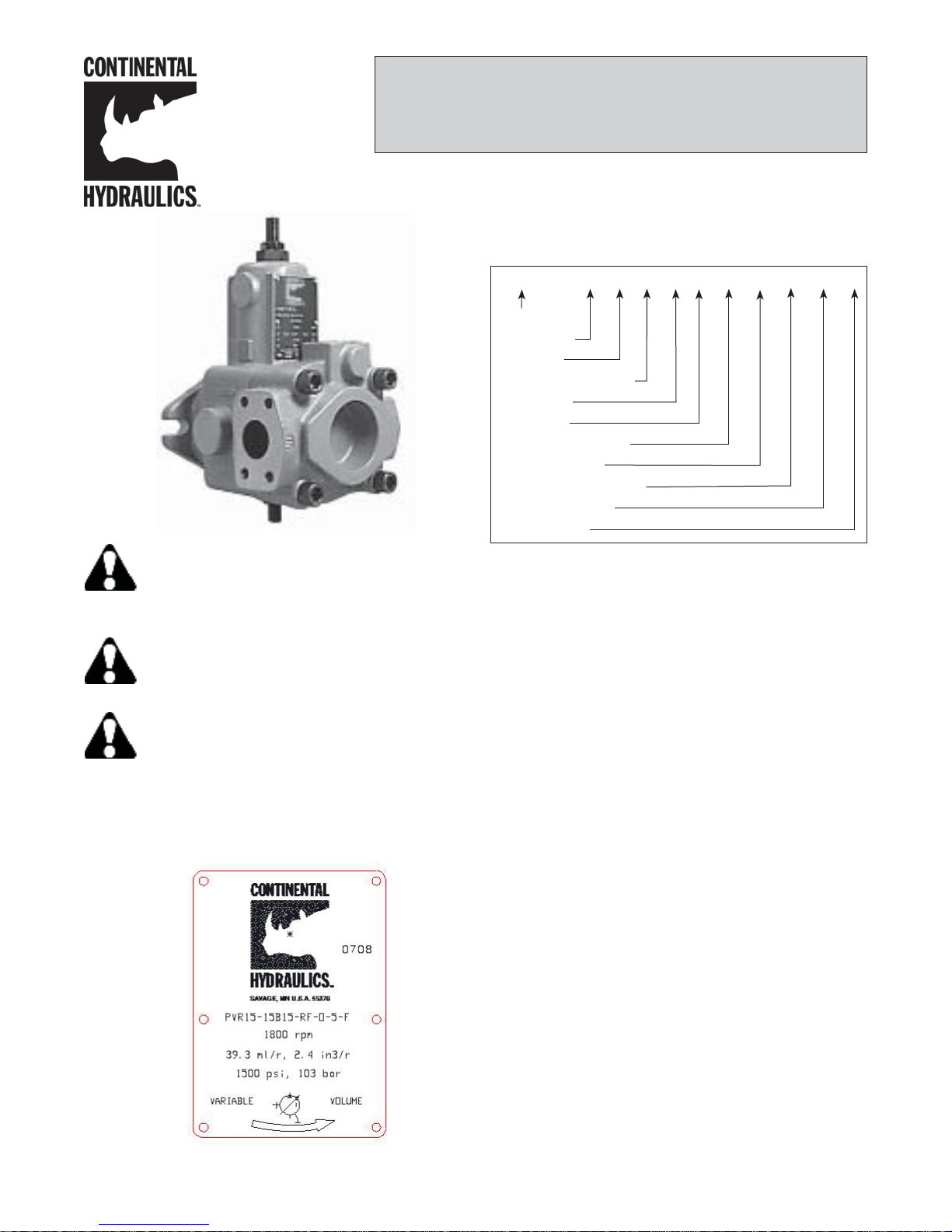
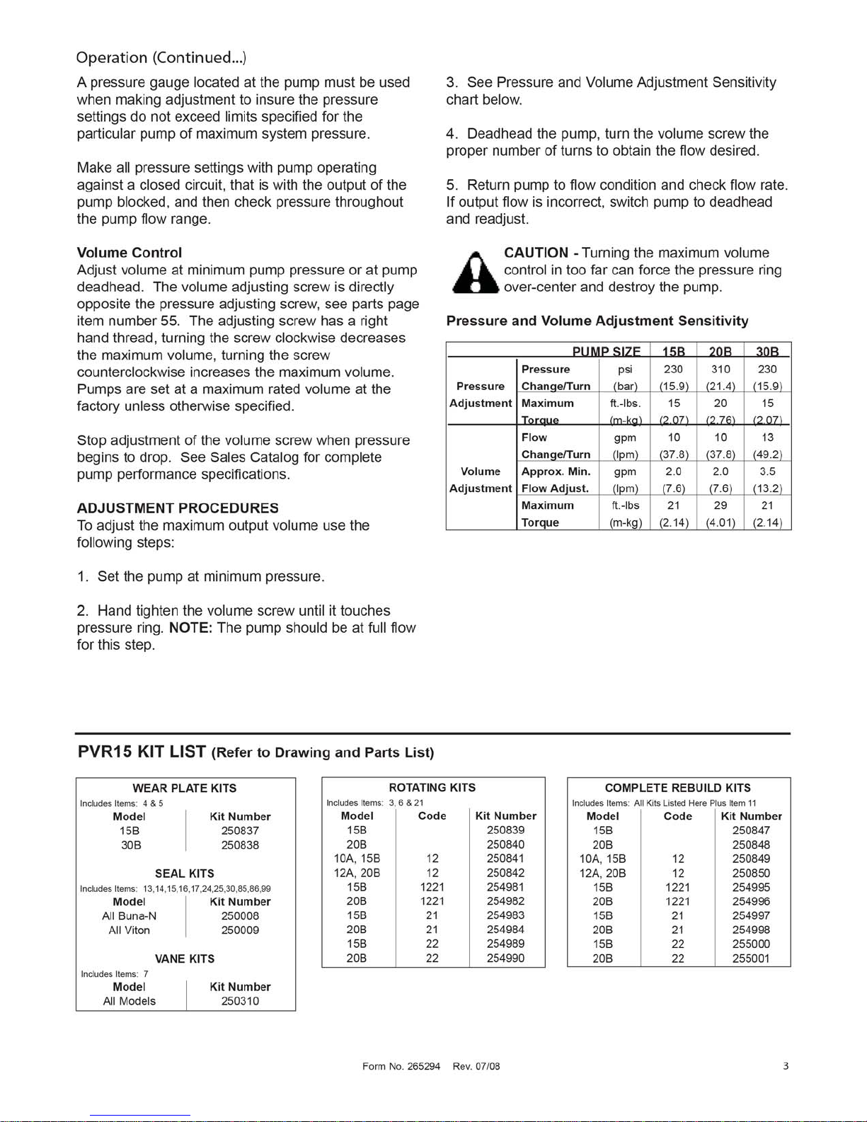
PRODUCT IDENTIFICATION
Each pump has an Ordering Code stamped on its
nameplate. See below for the location of the Ordering
Code.
This service manual applies to products with Ordering
Codes like the sample below.
PVR15 - _ _ _ - _ _ RF - _ - 5 - _ _ _ _ _ _ _ _ - F
Basic Pump
Pump Size
Pressure
Rotation & Mounting
Fluid Type
Seal Type
Mechanical Options
Control Options
Electrical Box Options
Solenoid Options
Design Letter
INSTALLATION
PUMP DRIVE AND MOUNTING
When mounting the pump and motor, care must be
taken to align the pump and motor shafts within .003
T.I.R. (0.076 mm) direct inline through a jaw type/
flexible web coupling. This is recommended for all
pumps. Tire-type flexing elements and chain-type
drives are not recommended. With belt drives, please
consult factory.
To avoid axial and radical end loading of the pump
shaft, do not couple the pump and motor shafts
rigidly. Allow freedom at the coupling for the two
shafts to ride independently.
To prevent end loading, the space between the pump
and motor shaft ends should be 3/4 inch (19.05 mm)
for PVR15 pumps, or as the coupling manufacturer
specifies.
PIPING AND RESERVOIR
The pump should be mounted with a minimum
number of elbows or fittings. The pump suction
should be at least 1-1/4 inch (31.75 mm) tube/pipe for
PVR15 pumps.
For any system and combination of piping except
High Water Based Fluids (HWBF), the vacuum at the
pump inlet must not exceed seven inches of Mercury,
(5 inch Hg. for fire resistant fluids). HWBF Pumps are
Form No. 265294 Rev. 07/08
1
Installation (Continued...)
to have a positive inlet head in the range of 0.5-inch
Hg. to 20 inch Hg.
Piping should be done with pickled pipe or seamless
tubing free of dirt and scale. Do not use galvanized
or other pipe that tends to flake off.
6. Set the machine controls to open the circuit and
allow free flow from the pump back to tank or connect
the pump outlet line directly to tank. Jog the motor on
and off several times (on two seconds, off three
seconds) until the pump is primed. Check pump for
proper direction of rotation during the jogging.
A 100-mesh screen (60 mesh for fire resistant and
HWBF) should be used on the pump suction line.
The screen should be located approximately two
inches (50.8 mm) from the bottom of the tank. All
lines returning oil to the tank should discharge at least
two inches (50.8 mm) below the minimum oil level
and should be separated from the pump suction area
by means of a baffle. These lines should also include
a 10-micron return line filter, with the exception of the
case drain line.
The pump case drain should be connected directly to
the tank. Pressure in excess of 10 psi (0.7 bar) in the
case drain line can result in shaft seal leakage. It is
recommended that the case drain be returned to the
tank by a separate 3/8-inch (9.5 mm) line.
STARTUP PROCEDURES
The following instructions apply for initial startup of
the hydraulic pump. After an extended shutdown
period, start with item 5.
CAUTION - Never start a new pump
installation against a blocked system.
1. Check the nameplate for model number and rpm.
The arrow on the pump casting indicates direction of
rotation.
2. Pump suction line should extend below the lowest
point of oil level but not less than two inches (50.8
mm) above reservoir bottom.
7. After the pump has been primed, run it for several
minutes at lower than normal pressures with an open
or intermittently open system which permits oil flow.
This will purge entrapped air from the pump and
system.
8. Neither volume adjustment nor pressure
adjustment should be adjusted until the pump has
been primed and running, and air is purged.
9. After air has been purged from the system, the
system can be closed and the pump adjusted to the
required operating pressure.
10. If necessary, the volume adjustment can be
adjusted to limit maximum output.
11. When replacing pumps, the suction screen in the
reservoir must be removed and thoroughly cleaned.
Also, the suction line from the reservoir to the pump
should be flushed inside and out to remove any
contaminants. Pieces of metal from a damaged pump
can back up into this line. If they are not removed,
they will be drawn into the new pump and destroy it.
Start unit by using proper pump start-up procedure
items 1 through 10.
CAUTION - If both pressure and volume
modifications are supplied on the pump, the
pressure should be adjusted before the
volume. Volume should be adjusted at minimum
pump pressure or at deadhead. Stop adjustment at
the volume screw when pressure begins to drop.
3. The pump and motor shafts must be aligned within
.003 inches (0.076 mm). See Pump Drive and
Mounting directions above for restrictions.
4. Connect the case drain directly to tank (or to a
heat exchanger if the pump will be deadheading for
long periods of time during operation), using a fullsize line corresponding to the case drain in the pump
or manifold. If connected to a heat exchanger, the
case drain line should be protected with a 10 psi (0.7
bar). maximum relief valve in parallel with the heat
exchanger. No other return lines should be connected
in common with the case drain return.
5. Rotate pump and motor by hand to insure free
rotation.
2
OPERATION
PRESSURE AND VOLUME ADJUSTMENTS
Pressure Control
All pumps are adjusted to reduced pressure before
shipment and must be readjusted to the required
system pressure after installation and start-up.
The pressure adjusting screw is located at the end
face of the compensator chamber. See parts page
item number 30. The adjusting screw has a right
hand thread; clockwise adjustment increases
pressure; counterclockwise reduces pressure.
Form No. 265294 Rev. 07/08
 Loading...