

Page 1
Continental Hydraulics Installation Manual
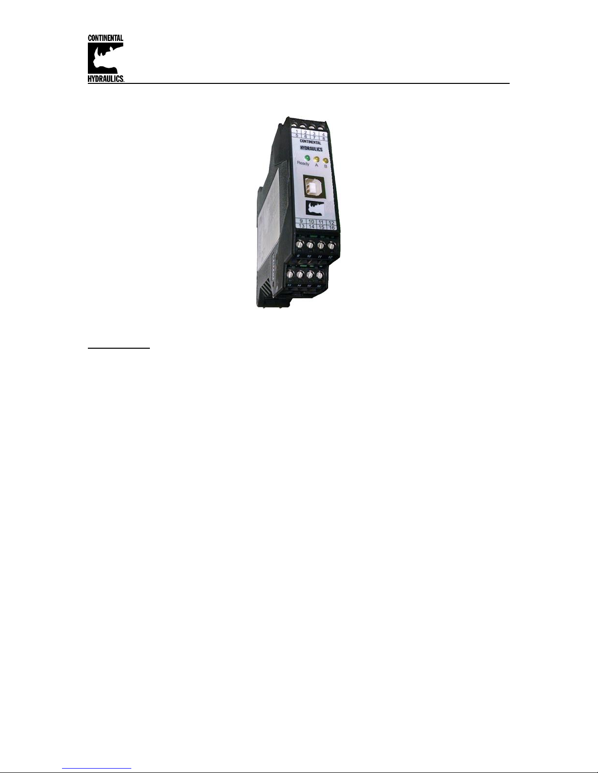
CEM-SA-B
Description:
This closed loop position module has been developed for controlling hydraulic positioning drives.
Proportional valves with integrated or external electronics can be controlled with the differential
output. Output is an analog signal of either voltage, 0 to +/- 10v or current 4-20mA, suitable for
directly driving a proportional directional valve with on board electronics.
The internal profile generation is optimized for stroke-dependent deceleration or the NC control
mode. The controller and the controller settings are factory preset to typical requirements and can
be optimized for the control behavior as required. The optimized control function offers a high
degree of precision together with high stability for hydraulic drives. The movement cycle is
controlled via the external position and speed inputs.
The high resolution of the analogue signals ensures good positioning behavior. A wide range of
analog signals are accepted. User may select either voltage or current input mode. These inputs
are easily scaled to match system requirements.
Forward and Reverse “jog” inputs allow for manual load control. A user definable window for “in
position” triggers an output for communication to the next machine function.
This module is easily adapted to a variety of system requirements. All variables are user adjusted
with easy to use CHI-PC software on your Microsoft Windows laptop. Control variables are
stored in non-volatile memory internal to the module. All variables can be read by the laptop, and
reproduced exactly on other modules.
Page 1 of 27 CEM-SA-B CHI 1020687 01/2016
Page 2

Continental Hydraulics Installation Manual
Table of Contents
Information Description Page #
Technical Data - ……………………………………….…………………….………..…………… 3
Functional Diagram …….…….…………………….……………………………………………... 4
Wiring Example…………………………………………………………………………………… 4
Dimensions …………………………………………….…………………………………………… 4
Terminal Identification …………………………………………………………………………….. 5
Steps to install and configure a new application ……………………….………………………. 6
Module Mounting Location ………………………………………….…………………………….. 7
Power Supply ………………………………………………………………………………….…… 7
Wiring to valve ……………………………………………………………………………………… 7
Parameter List …………………………………………….…………………………..…………… 8
LED Indications ……………………….…………………………………………………………… 9
Command Parameter Descriptions
LG (Language)…………………………………………………………………………… 10
MODE……………………………………………………………………………………... 10
SENS ……………………..……………………………………………………. ………... 10
EOUT …………………………………………………………………………………… 11
ENABLE…………………………………………………………………………………. 11
START (RUN)…………………………………………………………………………… 11
HAND:A / HAND :B……………………………………………………………………… 12
INPOS ……………………………………………………………………………………. 12
SYS_RANGE ……………………………………………………………………………. 12
SIGNAL: W/X/V.………………………………………………………………………… 13
N_RANGE:X …………………………………………………………………………….. 13
OFFSET:X ……………………………………………………………………………….. 13
Using SYS_RANGE, N_RANGE and OFFSET ……………………………………… 14
Speed Commands SIGNAL:V …………………………………………………………. 15
VELO ……………………………………………………………………………………… 15
VRAMP …………………………………………………………………………………… 15
VMODE …………………………………………………………………………………… 16
ACCEL ……………………………………………………………………………………. 16
VMAX ……………………………………………………………………………………. 16
A:A and A:B………………………………………………………………………………. 17
D:A / D:B / D:S …………………………………………………………………………… 17
V0:A / V0:B / V0:RES …………………………………………………………………… 18
PT1 ……………………………………………………………………………………….. 18
CTRL ……………………………………………………………………………………… 19
MIN:A / MIN:B ……………………………………………………………………………. 20
MAX:A / MAX:B …………………………………………………………………………. 20
TRIGGER ………………………………………………………………………………… 20
OFFSET ………………………………………………………………………………….. 21
SIGNAL:U ………………………………………………………………………………… 21
Special Command descriptions ……………………………………………………….. 22
DC:AV ……………………………………………………………………………………. 23
DC:DV ……………………………………………………………………………………. 23
DC:I ………………………………………………………………………………………. 23
DC:CR ……………………………………………………………………………………. 23
Process Data (Monitoring) …………………………………………………………….. 23
AINMODE………………………………………………………………………………… 24-25
Troubleshooting …………………………………………………………………………………… 26-27
Page 2 of 27 CEM-SA-B CHI 1020687 01/2016
Page 3

Technical data
Supply voltage [VDC] 12… 30 (incl. ripple)
Current requirement [mA] <100
External protection [A] 1 medium time lag
Digital inputs [V] logic 0: <2
[V] logic 1: >10
Input resistance [kOhm] 25
[V] logic 0: <2
[V] logic 1: >12 (50 mA)
Analogue inputs (sensor and
demand value signal)
[V] 0… 10; 25 kOhm
[mA] 4… 20; 240 Ohm
Signal resolution [%] 0,003 incl. Oversampling
(maximum resolution 1 µm )
Speed input [V] 0… 10; 90 kOhm
[mA] 4… 20; 240 Ohm
[%] 0,003
Analogue outputs
Voltage [V] 2 x 0… 10; differential output
[mA] 10 (max. load)
Signal resolution [%] 0,006
Current [mA] 4… 20; 390 Ohm maximum load
Signal resolution [%] 0,006
Controller sample time [ms] 1
USB in RS 232C Emulation
(9600… 57600 Baud, 1 stop bit,
no parity, echo mode)
Snap-on module to EN 50022
PA 6.6 polyamide
Flammability class V0 (UL94)
Weight [kg] 0,170
Protection class IP20
Temperature range [°C] -20… 60
Storage temperature [°C] -20… 70
Humidity [%] < 95 (non-condensing)
USB-B
4 x 4-pole terminal blocks
PE: via the DIN mounting rail
EN 61000-6-2: 8/2005
EN 61000-6-4: 6/2007 ; A1:2011
Connections
EMC
Digital outputs
Serial interface
Housing
Continental Hydraulics Installation Manual
Page 3 of 27 CEM-SA-B CHI 1020687 01/2016
Page 4
Continental Hydraulics Installation Manual
Power
Supply
15
16
Differential
Input on
Control Valve
+
-
3
4
12
1
2
Ready
In Pos
5
Start (Run)
Hand + (jog)
6
7
8
Hand - (jog)
Analog Position Feedback
Analog Command Position
Analog Speed (optional)
+24v
14/11
13/11
10/9
Gnd
+24v
Gnd
Valve out +
Enable
Speed
Command
Feedback
Valve out -
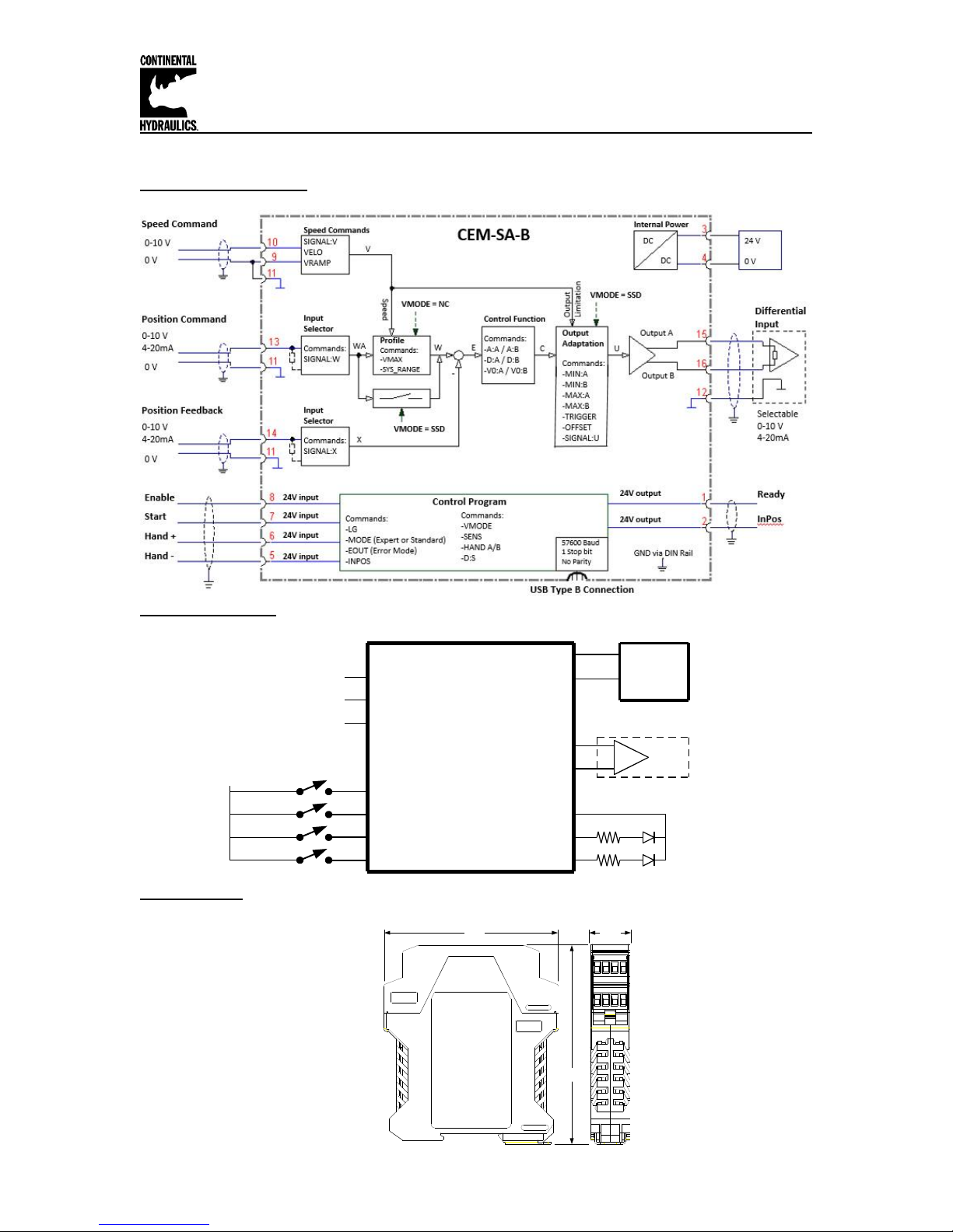
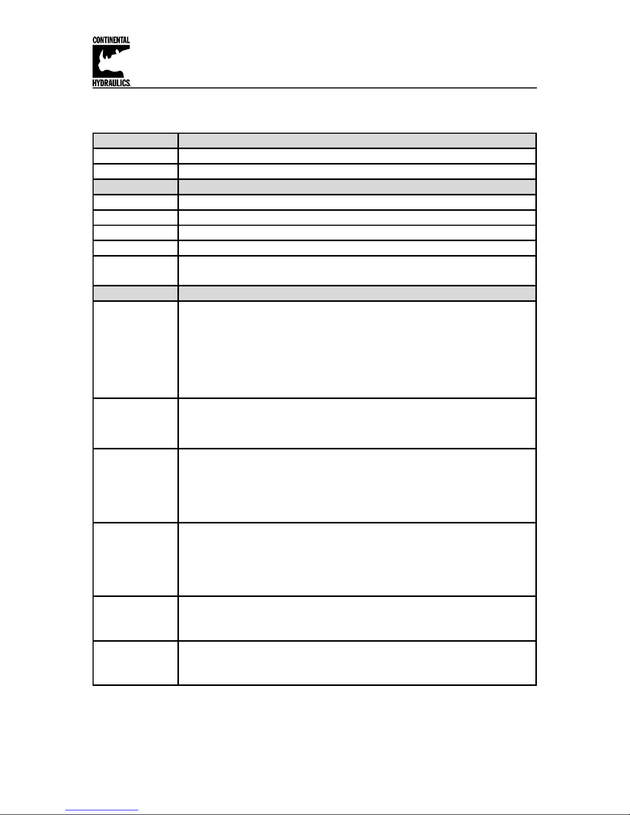
4.5"
3.9"
0.9"
Functional Diagram:
Wiring Example:
Dimensions:
Page 4 of 27 CEM-SA-B CHI 1020687 01/2016
Page 5
Continental Hydraulics Installation Manual
CEM-SA-B Input and output Terminal Identification
Connection
Supply
PIN 3
Power supply (see technical data)
PIN 4
0 V (GND) connection.
Connection
Analogue signals
PIN 9 / 10
External speed dem and (V), range 0… 10 V or 4… 20 m A (scalable)
PIN 13
Position dem and value (W), range 0… 10 V or 4… 20 mA (scalable)
PIN 14
Analogue pos ition actual value (X), range 0… 10 V or 4… 20 m A (scalable)
PIN 11 / PIN 12
0 V (GND) connection for analogue signals
Valve control Output signal.
Type of signal and polarity can be selected by the parameter SIGNAL:U.
Connection
Digital inputs and outputs
Enable input:
This digital input signal initializes the application and error messages are deleted. The
controller and the READY signal are activated. The output signal to the control element is
enabled.
The actual position is accepted as the command position and the drive remains
stationary under control at this position.
If the input is disabled, the output (control signal) is switched off(disabled). Take care of
the EOUT-command!
START (RUN) input:
The position controller is active and the external analogue demand position is accepted
as the demand value. If the input is disabled during the movement, the system is
stopped within the set emergency stopping distance (D:S).
HAND + input:
Manual operation (START = OFF): the drive moves at the programmed speed in the
programmed direction. After deactivation, the actual current position is accepted as the
demand position. The START (RUN) input has priority over the HAND+ input.
If the sensor signal is missing (external ENABLE signal = ON), the drive can be operated
in manual mode.
HAND - input:
Manual operation (START = OFF); the drive moves with the programmed speed in the
programmed direction. After deactivation, the actual current position is accepted as the
required position. The START (RUN) input has priority over the HAND- input.
If the sensor signal is missing (external ENABLE signal = ON), the drive can be operated
in manual mode.
READY output:
ON: The module is enabled; there are no discernable errors.
OFF: Enable (PIN 8) is disabled or an error (sensor or internal error) has been detected.
STATUS output:
ON: INPOS message. The axis is within the INPOS window.
OFF: INPOS message. The axis is outside the INPOS window.
PIN 2
PIN 15 / 16
PIN 8
PIN 7
PIN 6
PIN 5
PIN 1
Page 5 of 27 CEM-SA-B CHI 1020687 01/2016
Page 6
Continental Hydraulics Installation Manual
Steps to install and configure a new application:
All parameters are adjusted using VEA-BUSB programming cable and CHI-PC Microsoft
Windows application.
1. Mount the module in a suitable location
2. Connect the power supply and valve solenoids
3. Down load and open the GUI program (www.continentalhydraulics.com/wp-
content/uploads/2015/01/setup-CEWMPC-10-v3.5.0.zip )
4. Connect to Laptop via USB to USB Type B communication cable.
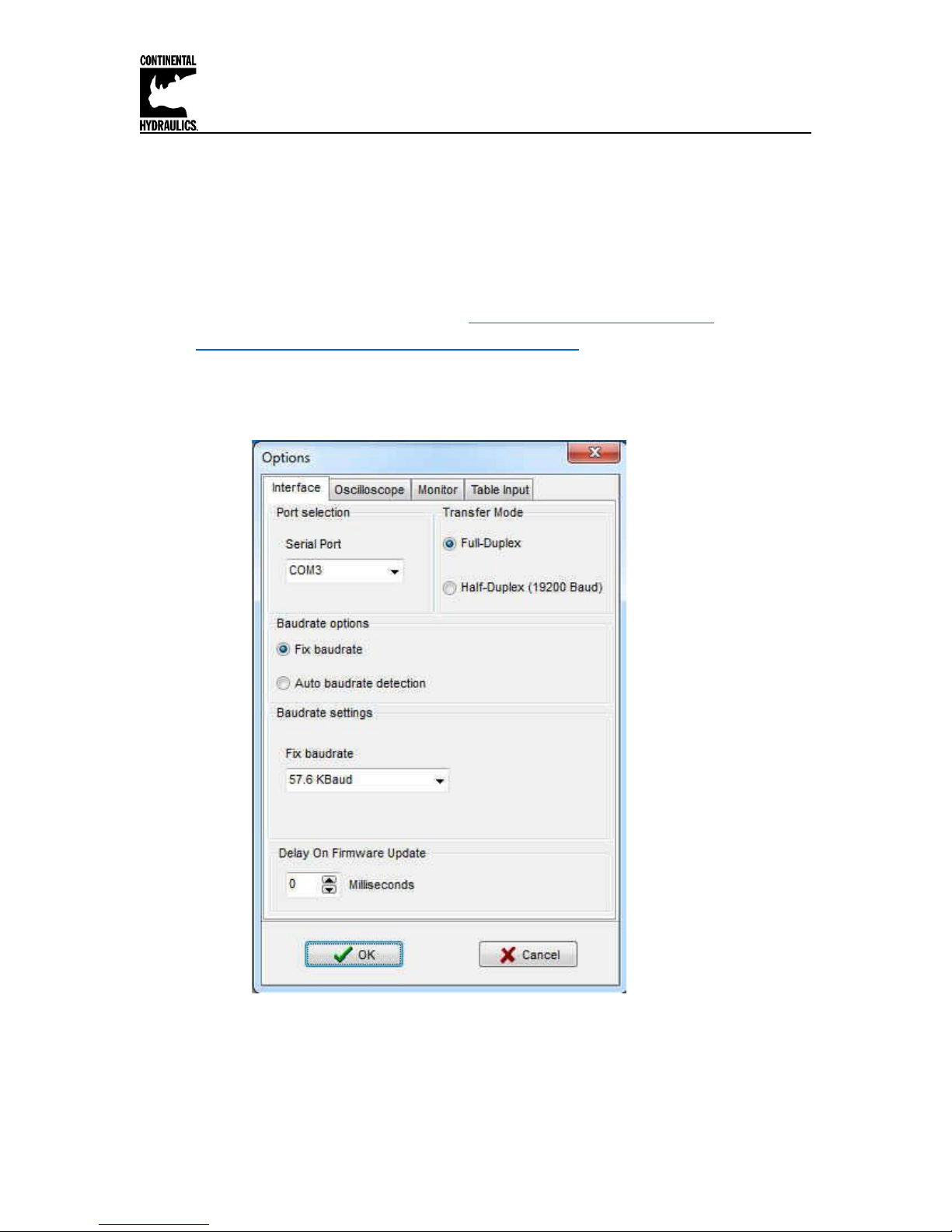
5. Open the Options and check setting make sure the correct com port, full-Duplex and
57.6K Baud rate are selected.
Page 6 of 27 CEM-SA-B CHI 1020687 01/2016
Page 7

Continental Hydraulics Installation Manual
Module Mounting Location:
This module is to be mounted in a cabinet for protection from the local environment.
Ensure there is adequate free space around the module to allow for cooling air flow.
This module is designed to snap onto an industry standard 35mm DIN rail.
Do not mount near other modules that emit high power electrical interference, such as motor
controllers and high power contactors.
Power Supply:
This module is designed to operate on DC power from a regulated power supply ranging from 12
to 30 volts. Match valve solenoid voltage rating to power supply, typically 12 or 24 volts.
A 1 amp medium action fuse is recommended in the “+” power supply line.
Wiring to Valve:
Two conductors are required for each solenoid. There is no need for shielding on these power
conductors.
Wire size is chosen to provide an acceptable voltage drop between the module and the valve
solenoid. The following chart is based on 5% drop for 12v and 24v applications. The listed cable
length is distance from module to valve, and includes the voltage drop of the return conductor.
Wire size 2.6A 12v 1.6A 24v 0.86A 24v
12 gauge 66 ft. max 215 ft. max 400 ft. max
14 gauge 49 ft. max 159 ft. max 295 ft. max
16 gauge 31 ft. max 100 ft. max 186 ft. max
18 gauge 19 ft. max 63 ft. max 117 ft. max
20 gauge 13 ft. max 39 ft. max 73 ft. max
22 gauge 8 ft. max 25 ft. max 46 ft. max
Page 7 of 27 CEM-SA-B CHI 1020687 01/2016
Page 8

Continental Hydraulics Installation Manual
Ref Page Command Parameter Help / Description STD EXP-SDD EXP-NC
10 LG EN EN English X X X
10 MODE EXP Standard / Expert mode X X X
10 SENS ON Malfunction monitoring [ON / OFF /AUTO] X X X
11 EOUT 0 Output signal if not ready [0.01%] X X
12 HAND:A 3333 Manual speed [0.01%] X X X
12 HAND:B -3333 Manual speed [0.01%] X X X
12 INPOS 200
In-position-window [µm] X X X
12 SYS_RANGE 100 Axis working Stroke [mm] X X X
13 SIGNAL:X U0-10 Type of Input X X X
13 N_RANGE:X 100 sensor nominal length [mm] X X X
13 OFFSET:X 0 sensor offset [µm] X X X
13 SIGNAL:W U0-10 Type of Input X X X
15 SIGNAL:V OFF Type of Input X X X
15 VELO 10000 Internal speed limitation [0.01%] X X X
15 VRAMP 200
Ramp time for the external speed [ms] [SINGNAL:V - ON] X
16 VMODE SDD Method of positioning X X
16 ACCEL 250
Acceleration [mm/s^2] X
16 VMAX 50 Maximum speed [mm/s] X
17 A:A 100 Acceleration time [ms] X X
17 A:B 100 Acceleration time [ms] X X
17 D:A 25 Deceleration stroke [mm] X X
17 D:B 25 Deceleration stroke [mm] X X
17 D:S 10 Overtravel [mm] X X
18 V0:A 25 Loop gain [1/s] X
18 V0:B 25 Loop gain [1/s] X
18 V0:RES 1 Loop gain resoluti on X
18 PT1 1 PR1-fi lter time constant [ms] X X
19 CTRL SQRT1 Control characteristic X X X
20 MIN:A 0 Compensation of the Deadband in 0.01% X X X
20 MIN:B 0 Compensation of the Deadband in 0.01% X X X
20 MAX:A 10000 Output Scaling in 0.01% X X X
20 MAX:B 10000 Output Scaling in 0.01% X X X
20 TRIGGER 200 Trigger point of the MIN function in 0.01% X X X
21 OFFSET 0 Output offset [0.01%] X X X
21 SIGNAL:U U+-10 Type and polarity of the output signal X X X
23 DC:I 2000 Drift compensator, I-gain [ms] X X
23 DC:AV 0 Drift compensator, activation value [0.01%] X X
23 DC:DV 0 Drift compensator, deactivation value [0.01%] X X
23 DC:CR 500 Drift compensator, control range [0.01%] X X
CEM-SA-B Function Parameter layout
MODE
Page 8 of 27 CEM-SA-B CHI 1020687 01/2016
Page 9

Continental Hydraulics Installation Manual
LEDs Description of the LED function
Identical to the READY output.
OFF: No power supply or ENABLE is not activated
ON: System is ready for peration
Flashing: Error discovered
Only active when SENS = ON
Identical to the STATUS output.
OFF: The axis is outside the INPOS window.
ON: The axis is within the INPOS window.
1. Chasing light (over all LEDs): The boot loader is active. No normal functions
are possible.
2. All LEDs flash shortly every 6 s: An internal data error was detected and corrected
automatically! The module still works regularly.
To acknowledge the error the module has to have power cycled.
YELLOW A +
YELLOW B
Both yellow LEDs flash oppositely every 1 s: The nonvolatile stored parameters are
inconsistent! To acknowledge the error, the data have to be saved with the SAVE
command or the corresponding button in the CHI-PC. If the function of the module has
changed via the FUNCTION parameter, all parameters are deleted purposely and set to
default values. In this case the LEDs indicate no error, but a desired state. To
acknowledge please save.
GREEN
YELLOW A
GREEN +
YELLOW A+B
LED Indications
Page 9 of 27 CEM-SA-B CHI 1020687 01/2016
Page 10

Continental Hydraulics Installation Manual
Command
Parameters
Unit
Group
LG x
x= DE|EN
-
STD
Command
Parameters
Unit
Group
MODE x
x= STD|EXP
-
STD
Command
Parameters
Unit
Group
SENS x
x= ON|OFF|AUTO
-
STD
Parameter Descriptions
LG (Changing the language)
Either English or German can be selected for the displayed texts.
After changing the language settings, the ID button in the menu bar (CHI-PC) must be pressed
(module identification).
MODE (Switching between parameter groups)
This command changes the operating mode. Various commands (defined via STD/EXP) are
blanked out in Standard Mode. The commands in Expert Mode have a more significant influence
on system behavior and should accordingly be changed with care. (see page 8)
SENS (monitoring of the modul functions)
This command is used to activate/deactivate the monitoring functions (4… 20 mA sensors, output
current, signal range and internal failures) of the module.
ON: All monitoring functions are active. Detected failures can be reset by deactivating the
ENABLE input PIN 8.
OFF: No monitoring function is active. The READY output will not function in OFF.
AUTO: Auto reset mode. All monitoring functions are active. If the failure doesn’t exist
anymore, the module automatically resumes to work without deactivating the ENABLE
input PIN 8.
Normally the monitoring functions are always active because otherwise no errors are
detectable via the READY output. Deactivating is possible mainly for troubleshooting.
Page 10 of 27 CEM-SA-B CHI 1020687 01/2016
Page 11

Continental Hydraulics Installation Manual
Command
Parameters
Unit
Group
EOUT x
x= -10000… 10000
0.01 %
EXP
1
EOUT (Output signal: READY = OFF)
Output value in case of a detected error or a deactive ENABLE input. A value (degree of valve
opening) for use in the event of a sensor error (or the module is disabled) can be defined here.
This function can be used if, for example, the drive is to move to one of the two end positions (at
the specified speed) in case of a sensor error.
|EOUT| = 0 The output is switched off in the event of an error. This is normal behavior.
CAUTION! If the output signal is 4… 20 mA, the output is switched off when |EOUT| = 0. If a null
value = 12 mA is to be output in the event of an error, EOUT must be set to 11.
The output value defined here is stored permanently (independently of the parameter set). The
effects should be analyzed by the user for each application from the point of view of safety.
Do not use the manual mode in conjunction with the EOUT command. After the deactivation of
the HAND input the output is set to the EOUT value.
ENABLE (pin 8) digital input:
ENABLE is a digital input that is active high.
When the ENABLE input is low, there is no output to the valve. Command input and feedback
input values are ignored. All other inputs are also ignored. To activate the HAND function,
ENABLE must be held active.
If ENABLE is removed during an active motion profile, the output to the valve is instantly brought
to zero.
START (RUN) (pin 7) digital input:
START (RUN) is a digital input that is active high.
Bringing pin 7 high (while holding pin 8 (ENABLE) high), forces the module into closed loop
position control mode.
If RUN is removed during an active motion profile, the output to the valve is ramped to zero.
This is necessary if using valves without error detection for signals lower than 4 mA. If the valve has an
error detection, it moves into a defined position after switching off the output.
Page 11 of 27 CEM-SA-B CHI 1020687 01/2016
Page 12

Continental Hydraulics Installation Manual
Command
Parameters
Unit
Group
HAND:i x
i= A|B
x= -10000… 10000
0.01%
STD
Command
Parameters
Unit
Group
INPOS x
x= 2… 200000
µm
STD
Command
Parameters
Unit
Group
SYS_RANGE ................................................................................................................................................... x
x= 10… 10000
mm
STD
HAND (Manual speed)
The Hand functions are not active when Start PIN 7 is active, to use the Hand manual speed
functions the Start function must be deactivated.
The manual speeds are set with these parameters. The drive moves in a controlled manner in the
defined direction when the manual signal is active. The direction is defined by the sign of the
parameters. After the manual signal has been disabled, the drive remains under control in the
current position.
In case of a fault (position sensor fault), the drive can still be moved with the manual function. The
output will be switched off when hand signals are turned off.
The manual speed is also limited by the (internal or external) speed demand (MIN evaluation).
Caution! Do not use the manual mode in conjunction with the EOUT command. After the
deactivation of the HAND input the output is set to the EOUT value.
INPOS (In position range)
This parameter is entered in µm.
The INPOS command defines a range for which the INPOS message is generated. This function
monitors the failure between the command and actual position. If the failure is less than the
programmed value a INPOS message at the status output (see Pin description). The positioning
process is not influenced by this message.
PIN 7 (START) must be activated to generate the INPOS messages.
SYS_RANGE (Working stroke)
This command defines the full stroke, which corresponds to 100 % of the input signal. If the
demand is set incorrectly, this leads to incorrect system settings, and the dependent parameters
such as speed and gain cannot be calculated correctly.
Page 12 of 27 CEM-SA-B CHI 1020687 01/2016
Page 13

Continental Hydraulics Installation Manual
Command
Parameter
Unit
Group
SIGNAL:i x
i= W|X|V
x= OFF
U0-10
U10-0
I4-20
I20-4
-
EASY
Command
Parameter
Unit
Group
N_RANGE:X
x
x= 10… 10000
mm
EASY
Command
Parameter
Unit
Group
OFFSET:X x
x= -100000… 100000
µm
EASY
2
SIGNAL (Type of input)
This command can be used to change the type of input signal (voltages or current) and to define
the direction of the signal. This command is available for all analog inputs (W, X, and V).
OFF= Deactivation of the input2.
See ANIMODE section (page 24-25) if the Signals used are not listed above, for re-scaling as
required.
N_RANGE: X (Nominal range of the sensor)
N_RANGE (nominal range or nominal stroke) is used to define the length of the sensor. This
value should be always higher than SYS_RANGE. The control parameter cannot be calculated
correctly in case of wrong values.
OFFSET: X (Sensor offset)
Adjustment of the zero point of the sensor.
The deactivation can be used to deactivate the velocity (speed) input PIN_9/10 (the VELO value is active).
Page 13 of 27 CEM-SA-B CHI 1020687 01/2016
Page 14

Continental Hydraulics Installation Manual
120,00 mm
100,00 mm
5,00 mm
Figure 1 (Input scaling of the sensor)
Using of the commands SYS_RANGE, N_RANGE: X and OFFSET: X
If the Cylinder stroke and the feedback device are matched, the standard factory settings will not
require any changes.
In systems where these are not matched, the commands SYS_RANGE, N_RANGE: X and
OFFSET: X must be scaled to match. The application scaling will be done by these three
commands.
In this example (Figure 1) the system is defined by a length of 120 mm of the sensor, a working
stroke of 100 mm of the cylinder and an offset of 5 mm. These parameters have to be typed in
and the axis is driving between 5 mm and 105 mm of the sensor stroke and between 0 mm and
100 mm of the cylinder stroke.
Correct scaling:
SYS_RANGE = 100 (mm)
N_RANGE: X = 120 (mm)
OFFSET: X = -5000 (µm)
Page 14 of 27 CEM-SA-B CHI 1020687 01/2016
Page 15

Continental Hydraulics Installation Manual
Command
Parameters
Unit
Group
VELO x
x= 1… 10000
0.01 %
SIGNAL:V =
OFF
Command
Parameters
Unit
Group
VRAMP x
x= 10… 5000
ms
SIGNAL:V
3
Speed commands
The SIGNAL: V command is used to switch over between external or internal speed limitations.
SIGNAL: V = OFF Internal speed limitation (VELO command)
SIGNAL: V = U0-10 External speed limitation (0-10 Volt)
PIN 9/10 is used for external speed limitation3.
See ANIMODE section (page 24-25) if the Signals used are not listed above, for re-scaling as
required.
VELO (Internal speed demand value)
Specification of the internal speed limitation.
VRAMP (Ramp time for external speed demand)
The rate of change of the external speed demand can be limited by this ramp time. The command
is only active if external speed demand (SIGNAL:V <> OFF) has been parameterized.
The output signal is directly limited in SDD mode (default mode). In NC mode the speed profile of the
generator is limited. The lowest adjustable speed is 0.01 mm/s (VMAX = 1 mm/s and VELO = 1 %).
Page 15 of 27 CEM-SA-B CHI 1020687 01/2016
Page 16

Continental Hydraulics Installation Manual
Command
Parameters
Unit
Group
VMODE x
x= SDD|NC
EXP
Command
Parameters
Unit
Group
ACCEL x
x= 1… 20000
mm/s²
VMODE=NC
Command
Parameters
Unit
Group
VMAX x
x= 1… 2000
mm/s
VMODE=NC
VMODE (Methode of positioning)
The fundamental control structure can be changed with this parameter.
SDD: Stroke-Dependent Deceleration. In this mode, stroke-dependent deceleration is
activated. This mode is the default mode and is suitable for most applications. With
stroke-dependent deceleration, the drive comes to a controlled stop at the target
position. From the deceleration setpoint, the drive then switches to closed loop control
mode and moves accurately to the desired position. This control structure is very
robust and is insensitive to external influences such as fluctuating pressures. One
disadvantage is that the speed varies with the fluctuating pressure as the system runs
under open-loop control.
NC: Numerically Controlled. In this mode a position profile is generated internally. The
system always works under control and uses the following error to follow the position
profile. The magnitude of the following error is determined by the dynamics and the
closed loop gain. The advantage is that the speed is constant (regardless of external
influences) due to the profile demand. Because of continuous control, it is necessary
to run at less than 100 % speed, as otherwise the errors cannot be corrected. 70… 80
% of the maximum speed is typical although especially the system behavior and the
load pressure should be taken into account when specifying the speed.
ACCEL (Acceleration in NC mode)
This command is used to define the acceleration rate in NC mode. The command is only active if
the VMODE has been parameterized to NC.
VMAX (Maximum speed in NC mode)
Specification of the maximum speed in NC mode. This value is defined by the drive system and
should be specified as precisely as possible (not too high under any circumstances). The speed
is scaled by means of the VELO value or via the external speed demand (PIN 10 and 9). The
command is only active if the VMODE has been parameterized to NC.
Page 16 of 27 CEM-SA-B CHI 1020687 01/2016
Page 17

Continental Hydraulics Installation Manual
Command
Parameters
Unit
Group
A:i x
i= A|B
x= 1… 5000
ms
VMODE=SDD
Command
Parameters
Unit
Group
D:i x
i= A|B|S
x= 1… 10000
mm
VMODE = SDD
i
Intern
D
STROKE
G
4
A:A and A:B (Acceleration (ramp) time)
Ramp function for the 1st (A solenoid) and 3rd (B solenoid) acceleration quadrants only.
The acceleration time for positioning is dependent on the direction. “A” corresponds to connection
15 and “B” corresponds to connection 16 (if POL = +).
Normally A = flow P-A, B-T and B = flow P-B, A-T.
For quadrants 2 and 4, parameters D:A and D:B are used as the deceleration distance demand
when the SDD funcion is in control.
D:A / D:B / D:S (Deceleration / braking distance)
This parameter is specified in mm4.
The deceleration stroke is set for each direction of movement (A or B). The control gain is
calculated internally depending on the deceleration distance. The shorter the deceleration
distance, the higher the gain. A longer deceleration distance should be specified in the event of
instability.
Parameter D:S is used as the stopping ramp when disabling the START (PIN 7) signal. After
disabling, a new target position (current position plus D:S) is calculated in relation to the speed
and is specified as a command value.
Calculation of control gain
CAUTION: If the maximum stroke (SYS_RANGE command) is changed, the deceleration
distance must also be adjusted. Otherwise this can result in instability and uncontrolled
movements.
CAUTION! In older modules this parameter was specified in % of the maximum stroke. Since data
specification for this module has now been converted to mm, the relationship between the stroke
(SYS_RANGE command) and these parameters must be taken into account.
Page 17 of 27 CEM-SA-B CHI 1020687 01/2016
Page 18

Continental Hydraulics Installation Manual
Command
Parameters
Unit
Group
V0:i x
i= A|B
x= 1… 400
s-1
VMODE = NC
i
Intern
i
D
STROKE
G
V
v
D
0
max
Command
Parameters
Unit
Group
V0:RES x
x= 1|100
-
VMODE = NC
Command
Parameter
Unit
Group
PT1 x
x= 0… 300
ms
EXP
5
6
V0:A / V0:B (Loop gain setting)
This parameter is specified in s-1 (1/s).
In NC Mode normally the loop gain is specified rather than the deceleration stroke5.
The internal gain is calculated from this gain value together with the parameters VMAX and
SYS_RANGE.
Calculation of the internal control gain
In NC Mode the following error at maximum speed is calculated by means of the loop gain. This
following error corresponds to the deceleration stroke with stroke-dependent deceleration. The
conversion and therefore also the correct data demands related to the closed loop control system
are relatively simple if the relationship described here is taken into account.
V0:RES (Scaling of the loop gain)
V0:RES = 1 loop gain in s-1 (1/s) units.
V0:RES = 100 loop gain in 0.01 s-1 units6.
The increased resolution should be used in case of V0 < 4.
PT1 (Timing of the controller)
This parameter can be used to change the internal timing of the control function.
Hydraulic drives are often critical to control especially in case of high speeds and very fast valves.
The PT1 filter can be used to improve the damping rate and allows therefore higher loop gains.
Requirements for the use are: The natural frequency of the valve should be equal or higher than
the natural frequency of the drive.
The loop gain is alternatively defined as a KV factor with the unit (m/min)/mm or as V0 in 1/s. The
conversion is
KV = V0/16,67.
In case of very low loop gains (1 s-1 to 3 s-1) the better resolution of the adjustment should be selected.
Page 18 of 27 CEM-SA-B CHI 1020687 01/2016
Page 19

Continental Hydraulics Installation Manual
Command
Parameters
Unit
Group
CTRL x
x=
LIN|SQRT1|SQRT2
-
STD
7
Figure 2 (Braking function with respect to stroke and time)
Stroke
Velocity
Braking stroke
D:A or D:B
CTRL = LIN
CTRL = SQRT
Time
Velocity
Deceleration time
D:A or D:B
CTRL = LIN
CTRL = SQRT
CTRL (Deceleration characteristics)
The deceleration characteristic is set with this parameter. In case of positively overlapped
proportional valves the SQRT function should be used. The non-linear flow function of these
valves is linearized by the SQRT7 function.
In case of zero lapped valves (control valves and servo valves) the LIN or SQRT1 function should
be used regardless of the application. The progressive characteristic of the SQRT1 function has
better positioning accuracy but can also lead to longer positioning times in individual cases.
LIN: Linear deceleration characteristic (gain is increased by a factor of 1).
SQRT1: Root function for braking curve calculation. The gain is increased by a factor of 3 (in
the target position). This is the default setting.
SQRT2: Root function for braking curve calculation. The gain is increased by a factor of 5 (in
the target position). This setting should only be used with a significantly progressive
flow through the valve.
The SQRT function generates constant deceleration and thus reaches the target position faster. This is
achieved by increasing the gain during the deceleration process.
Page 19 of 27 CEM-SA-B CHI 1020687 01/2016
Page 20

Continental Hydraulics Installation Manual
Command
Parameters
Unit
Group
MIN:i x
MAX:i x
TRIGGER x
i= A|B
x= 0… 6000
x= 3000… 10000
x= 0… 4000
-
0.01 %
0.01 %
0.01 %
STD
MAX:A
MIN:A
MIN:B
MAX:B
Input
Output
non lineare Flow
compensation
Standard deadband
compensation
TRIGGER
8
MIN:A / MIN:B (Dead band compensation)
MAX:A / MAX:B (Output scaling)
TRIGGER (Response threshold for the MIN parameter activation)
The output signal to the valve is adjusted by means of these commands. A kinked volume flow
characteristic is used instead of the typical overlap step for the position controls. The advantage
is better and more stable positioning behavior. At the same time, kinked volume flow
characteristics can also be adjusted with this compensation8.
If there should also be adjustment options for deadband compensation on the valve or valve
amplifier, it must be ensured that the adjustment is performed either at the power amplifier or in
the module.
If the MIN value is set too high, this has an effect on the minimum speed, which can then no
longer be adjusted. In extreme cases this leads to oscillation around the controlled position.
Various manufacturers have valves with a defined nonlinear curve: e.g. a kink at 40 or 60 %
(corresponding to 10 % input signal) of the nominal volume flow. In this case the TRIGGER value should be
set to 1000 and the MIN value to 4000 (6000).
If zero lapped or slightly underlapped valves are used, the volume flow gain in the zero range (within the
underlap) is twice as high as in the normal working range. This can lead to vibrations and jittery behavior. To
compensate this, the TRIGGER value should be set to approximately 200 and the MIN value to 100. The
gain in the zero point is thus halved and an overall higher gain can often be set.
Page 20 of 27 CEM-SA-B CHI 1020687 01/2016
Page 21

Continental Hydraulics Installation Manual
Command
Parameters
Unit
Group
OFFSET x
x= -4000… 4000
0.01 %
STD
Command
Parameter
Unit
Group
SIGNAL:U x
x= U+-10
I4-12-20
U-+10
I20-12-4
-
EXP
9
OFFSET (Zero correction)
This parameter is entered in 0.01% units.
The offset value is added to the output value. Valve zero offsets can be compensated with this
parameter.
SIGNAL:U (Type and polarity of the output signal)
This command is used to define the output signal (voltage or current) and to change the polarity9.
Differential output ± 100 % corresponds with ± 10 V (0… 10 V at PIN 15 and PIN 16).
Current output ± 100 % corresponds with 4… 20 mA (PIN 15 to PIN 12). 12 mA (0 %) = center
point of the valve.
An output current of << 4 mA indicates an error and the module is disabled. The current input of
the proportional valves should be monitored by the valve. The valve have to be deactivated in
case of < 4 mA input signal. Otherwise the EOUT command can be used to get a defined output
signal.
See ANIMODE section (page 24-25) if the Signals used are not listed above, for re-scaling as
required.
The older POL command is removed.
Page 21 of 27 CEM-SA-B CHI 1020687 01/2016
Page 22

Continental Hydraulics Installation Manual
10
11
Special commands
Drift compensation / high accurate positioning
The high accurate positioning or the drift compensation can be used in case of external influence
which is limiting the positioning accuracy. This function could be critical if limit cycling10 by wrong
parameterization or the system behavior was not taken into account.
Which positioning errors can be compensated11?
1. Zero point adjustment of the valve. By this kind of failure, a constant offset between
command and feedback signal remains. This failure is more or less constant.
2. Zero point failure depending on the temperature. The same behavior as point 1, but the
failure is increasing slowly (over the temperature).
3. Position failure caused by an external force. All control and servo valves have a typical
pressure gain characteristic. In case of external forces an output signal of 2…3 % has to
be generated for the compensation of this force. And this signal is proportional to the
positioning error. Compared with point 1 and 2, the positioning failure generated by the
force signal can vary cycle to cycle.
How does it work?
High accurate positioning
These kinds of position errors should be compensated when the axis is near by the target
position. The output signal is going lower and lower but a system specific position error remains.
At the activation point this function – a slowly working integrator – is active. This integrator signal
is added to the output signal and will compensate offsets and other failure. To prevent
instabilities, the integrator value will be frozen when the output value is lower than the
deactivation point.
Typical setup
Valve pressure gain: 2.5 %; the activation point has to be set to 3… 5 % (DC:AV 300… 500).
Valve hysteresis: 0.5 %; the deactivation point has to be set to 0.7… 1.0 % (DC: DV 70… 100).
The lower the value the better the accuracy.
DC:CR should be equal to DC:AV.
The optimum integrator time has to be determined experimentally. Starting with higher values is
recommended.
The “limit cycling” is a small and permanent oscillation around the target position. The main reason are
static frictions and the hysteresis of the valve. By proper parameter setting, this can be avoided under the
boundary condition that the desired accuracy is not achieved. In this case, the hydraulic system is the
limiting factor in the accuracy.
This is relevant for zero lapped control valves and servo valves.
Page 22 of 27 CEM-SA-B CHI 1020687 01/2016
Page 23

Continental Hydraulics Installation Manual
Command
Parameter
Unit
Group
DC:AV x
DC:DV x
DC:I x
DC:CR x
x= 0… 2000
x= 0… 1000
x= 0… 2000
x= 0… 500
0.01 %
0.01 %
ms
0.01 %
EXP
Command
Description
Unit
WA
W
V
X
E
C
U
IA
IB
Demand value (input signal)
Demand value (according to the profile generator)
Speed input
Actual value
Error value
Output of the controller
Output signal of the module
Solenoid current A
Solenoid current B
mm
mm
%
mm
mm
%
%
mA (P Version only)
mA (P Version only)
DC:AV (Activation value)
DC:DV (Deactivation value)
DC:I (Integrator time)
DC:CR (Integrator limitation)
DC:AV This parameter is used to define the activation point (activation value). The DC
function is completely deactivated in case of DC: AV = 0.
DC:DV This parameter is used to define the deactivation point (DV = deactivation
value) Within the deactivation window no compensation value will be calculated
(frozen state). DC: AV = 0 should be used for best positioning, but „limit cycling
“can occur. This value should be set to 50 % of an acceptable error.
DC:I This parameter is used to define the integrator time. The lower this value the
faster the compensation. Low values will result in „limit cycling“.
DC:CR the output range of the DC function will be limited (CR = control range) by this
parameter.
PROCESS DATA (Monitoring)
The process data are the variables which can be observed continuously on the
monitor or on the oscilloscope
Page 23 of 27 CEM-SA-B CHI 1020687 01/2016
Page 24

Continental Hydraulics Installation Manual
AINMODE
The AINMODE is used to define the type of analog input signals being used.
The standard default setting of AINMODE is EASY. In the EASY mode the SIGNAL:W/X/V (see
page 13) are only available in the most commom 0-10 volt or 4-20mA values.
If the input signal being used are not as listed, the AINMODE is available in the MATH mode
where the input signals can be scaled by a linear equation.
To enter the MATH option, you must change the AINMODE to MATH by use of the Terminal
Window. (see steps 1-4 below)
Once in the Termainal Window screen type in AINMODE MATH and click the Save button. At this
time you may go back to the Parameter screen where you can use the user defined scalling
feature.
Once in the MATH mode you will be able to scale the various input signals as shown below.
Page 24 of 27 CEM-SA-B CHI 1020687 01/2016
Page 25

Continental Hydraulics Installation Manual
Command
Parameters
Unit
Group
FUNCTION
AIN:I a b c x
i = A|B
a= -10000… 10000
b= -10000… 10000
c= -10000… 10000
x= V|C
-
-
-
0.01%
-
EXP
AA
A-B
Command
Input
Description
AIN:X 1000 1000 0 V
0… 10 V
Range: 0… 100 %
AIN:X 10 8 1000 V OR
AIN:X 1000 800 1000 V
1… 9 V
Range: 0… 100 %; 1 V = 1000 used for the offset and
gained by 10 / 8 (10 V divided by 8 V (9 V -1 V))
AIN:X 10 4 500 V OR
AIN:X 1000 400 500 V
0.5… 4.5 V
Range: 0… 100 %; 0.5 V = 500 used for the offset and
gained by 10 / 4 (10 V divided by 4 V (4.5 V -0.5 V))
AIN:X 20 16 2000 C OR
AIN:X 2000 1600 2000 C OR
AIN:X 1250 1000 2000 C
4… 20mA
Range: 0… 100 %
The offset will be compensated on 20 % (4 mA) and the
signal (16 mA = 20 mA – 4 mA) will be gained to 100 %
(20 mA).
Each of this parameterization for 4… 20 mA is setting the
range to 0… 100 %.
Analogue input scaling parameters
This command offers an individual scalable input. The following linear equation is used for the
scaling.
Output = A/B ∙ (Input – C)
The “C” value is the offset (e.g. to compensate the 4 mA in case of a 4… 20 mA input signal).
The variables A and B are defining the gain factor with which the signal range is scaled up to
100 % (e.g. 1.25 if using 4… 20mA input signal, defined in default current settings by A = 1250
and B = 1000). The internal shunt for the current input signal is activated when parameters AIN:A
and AIN:B are set to Current (X=C).
The gain factor is calculated by dividing total input signal range (A) by the actual input range (B).
In the case of a 4-20mA with a single solenoid valve, the total range is 0-20mA, which means
A=20. The actual range is 4-20 mA, therefore, B= (20-4) =16. An offset, C, must be added to
compensate for the 0-4mA not being used of the full range. The offset is 4mA/20mA=0.2 or 20%.
Therefore C=2000 since the unit value for C is 0.01%.
Shown in the below table are the most common input command signal and the corresponding
settings to be used.
Typical settings (examples):
Page 25 of 27 CEM-SA-B CHI 1020687 01/2016
Page 26

Continental Hydraulics Installation Manual
FAULT
CAUSE / SOLUTION
ENABLE is active,
the module does
not respond and
the READY LED is
off.
There is presumably no power supply or the ENABLE signal (PIN 8) is not
present.
If there is no power supply, there is also no communication via our operating
program. If a connection has been made to the CHI-PC, then a power supply is
also available.
If the power supply exists, an attempt should be made to see whether the
system can be moved by means of the HAND+ and HAND- inputs (measuring
the output signal to the valve helps).
ENABLE is active,
the READY LED is
flashing.
The flashing READY LED signals that a fault has been detected by the module.
The fault could be:
A broken cable or no signal at the input (PIN 13 or PIN 14), if 4… 20 mA
signals are parameterized.
Internal data error: press the command/SAVE button to delete the data
error. The system reloads the DEFAULT data.
With the CHI-PC operating program the fault can be localized directly via the
monitor.
ENABLE is active;
the READY LED is
on, the system
moves to an end
position.
The control circuit polarity is incorrect. The polarity can be changed with the
POL command or by reversing the connections to PIN 15 and PIN 16.
ENABLE is active,
the READY LED is
on, the STATUS
LED is not on, the
system moves to
the target position
but doesn’t reach it
(positioning error).
Serious positioning errors can result from incorrect parameterization or
incorrect system design.
Is the cylinder position specified correctly?
Are the deceleration strokes correct (to start the system, the deceleration
distances should be set to approx. 20… 25 % of the cylinder position 12)?
Is the valve a zero lapped control valve or a standard proportional valve?
In the case of a proportional valve, the valve overlap which may be present
should be compensated for with the MIN parameters. Typical values are to
be found in the valve data sheet.
ENABLE is active,
The system is working and also actuating the valve.
12
Troubleshooting
It is assumed that the device is in an operable state and there is communication
between the module and the CHI-PC. Furthermore, the valve control
parameterization has been set with the assistance of the valve data sheets.
The stability criterion of the hydraulic axes must be taken into account.
Page 26 of 27 CEM-SA-B CHI 1020687 01/2016
Page 27

Continental Hydraulics Installation Manual
FAULT
CAUSE / SOLUTION
the READY LED is
on, and the system
oscillates on the
target.
Various potential problems could be:
The parameterization is not yet adjusted to the system (gain too high).
There is severe interference on the power supply.
Very long sensor cables (> 40 m) and sensor signal interference.
The MIN setting to compensate the valve overlap is too high.
As a basic principle, the parameterization of the sensor data and the controller
settings must be carried out first (before switching on). An incorrect demand is
equivalent to incorrect system design which then leads to incorrect operation. If
the system oscillates, the gain should first be reduced (longer deceleration
distances for D:A and D:B) and in the case of overlapped valves the MIN
parameter should also be reduced.
Speed too low
The drive may be able to move to position but the speed is too low.
Check the control signal to the valve.
Via the integrated oscilloscope (U variable).
Measure the signal to the valve with an external oscilloscope / voltmeter.
If the control is within the range of ± 100 % (± 10 V), the fault must be
sought in the hydraulics.
If the control signal is relatively low, the following points should be checked:
Is the internal/external speed signal limiting the speed?
Which setting has been specified for the deceleration
distance in relation to the POSITION?
Speed too high
The drive should move to position. The drive moves in and out too fast leading
to uncontrolled behavior. Reducing the speed (MAX or VELO parameter) has
very little or no effect.
The hydraulic system is over-sized. The entire parameterization of the
movement cycle cannot be reproduced (overlap and deceleration distance
settings)
Page 27 of 27 CEM-SA-B CHI 1020687 01/2016
 Loading...