

Page 1

Continental Hydraulics Installation Manual
CEM-PA-B
Product Description:
This closed loop PID amplifier, drives a single solenoid proportional pressure or flow
control valve coil up to 2.6A. It is suitable to provide precise closed loop control in
pressure, force, or velocity systems. This module uses traditional PID error correction to
provide stable control in dynamic systems.
A wide range of analog signals are accepted. User may select either voltage or current
input mode. These inputs are easily scaled to match system requirements. Input
command can be ramped. PID variables are adjustable over a wide range. The
Amplifier is easily switched from open loop to closed loop control.
Min and Max output current are adjustable. Output characteristics can be independently
customized. The module is disabled if the coil outputs are shorted or open. If command
current signal is outside of the proper range, the module is disabled. PWM and Dither
are user adjustable.
This module is easily adapted to a variety of system requirements. All variables are user
adjusted with easy to use software on your Microsoft Windows laptop. Control variables
are stored in non-volatile memory internal to the module. All variables can be read by
the laptop, and reproduced exactly on other modules.
Page 1 of 24 CEM-PA-B CHI 1020688 01/2016
Page 2

Continental Hydraulics Installation Manual
Table of Contents
Information Description Page #
Technical Data ………………………………………………………………….. 3
Steps to install and configure a new application ……………………………. 4-5
Module Mounting Location …………………………………………………….. 5
Power Supply …………………………………………………………………… 5
Wiring to Valve ………………………………………………………………….. 5
Circuit Diagram …………………………………………………………………. 6
LED Definitions …………………………………………………………………. 7
Terminal Identification ………………………………………………………….. 7
Parameter List …………………………………………………………………… 8
Command Parameter Descriptions
LG (Language) ………………………………………………………….. 9
MODE ……………………………………………………………………. 9
SENS …………………………………………………………………….. 9
EOUT …………………………………………………………………….. 10
SYS_RANGE ……………………………………………………………. 10
SIGNAL:X / SIGNAL:W ………………………………………………… 10
AINMODE (Signal Scaling mode)……………………………………… 11-12
N_RANGE:X …………………………………………………………….. 13
OFFSET:X ……………………………………………………………….. 13
RA:UP / RA:DOWN (Ramp times) …………………………………….. 14
C:P, C:I, C:D, C:D_TI, C:D_FF ………………………………………… 15
C:I_LIM / C:I_ACT ………………………………………………………. 16
MIN ………………………………………………………………………... 17
MAX ………………………………………………………………………. 17
TRIGGER ………………………………………………………………… 17
SIGNAL:U ………………………………………………………………… 18
CURRENT ……………………………………………………………….. 18
DFREQ / DAMPL ………………………………………………………... 18
PWM ……………………………………………………………………… 19
ACC ………………………………………………………………………. 19
PPWM / IPWM …………………………………………………………… 20
Process Data (Monitoring) ……………………………………………………… 20
Failure Monitoring ……………………………………………………………….. 21
Troubleshooting …………………………………………………………………. 22-24
Page 2 of 24 CEM-PA-B CHI 1020688 01/2016
Page 3

Technical data
Supply voltage [VDC] 12… 30 (incl. ripple)
Current requirement [mA] 60 + solenoid current
External protection [A] 3 medium time lag
Reference voltage [V] 8 (max. 25 mA load)
Digital inputs [V] logic 0: < 2
[V] logic 1: > 10
Input resistance [kOhm] 25
[V] logic 0: < 2
[V] logic 1: > 12 (50 mA)
Analogue inputs:
Command value [V] 0… 10; 150 kOhm
[mA] 4… 20; 390 Ohm
Signal resolution [%] 0.006 incl. Oversampling
Sensor value [V] 0… 10; 90 kOhm
[mA] 4… 20; 390 Ohm
Signal resolution [%] 0.006 incl. Oversampling
PWM output [A]
0.5, to 2.6 Amp; broken wire and short circuit
monitored
PWM frequency [Hz] 61… 2604
Sample time (pressure control) [ms] 1
Sample time (solenoid current
control)
[ms] 0.125
USB type B
Virtual COM port driver (CHI-PC):
9600… 57600 Baud (Default = 57600),
1 Stop bit, No parity, No handshake
Snap-on module to EN 50022
PA 6.6 polyamide
Flammability class V0 (UL94)
Weight [kg] 0,190
Protection class IP20
Temperature range [°C] -20… 60
Storage temperature [°C] -20… 70
Humidity [%] < 95 (non-condensing)
USB Typ B
4 x 4-pole terminal blocks
PE: via the DIN mounting rail
EN 61000-6-2: 8/2005
EN 61000-6-4: 6/2007 + A1:2011
EMC
Digital outputs
Serial interface
Housing
Connections
Continental Hydraulics Installation Manual
Page 3 of 24 CEM-PA-B CHI 1020688 01/2016
Page 4
Continental Hydraulics Installation Manual
Steps to install and configure a new application:
All parameters are adjusted using VEA-BUSB-A programming cable and CHI-PC Microsoft
Windows application.
1. Mount the module in suitable location. See page 5.
2. Connect the power supply, valve connections and enable.
3. Download and open the GUI program (www.continentalhydraulics.com/wp-
content/uploads/2015/01/setup-CEWMPC-10-v3.5.0.zip)
4. Connect to laptop via USB to USB Type B communication cable.
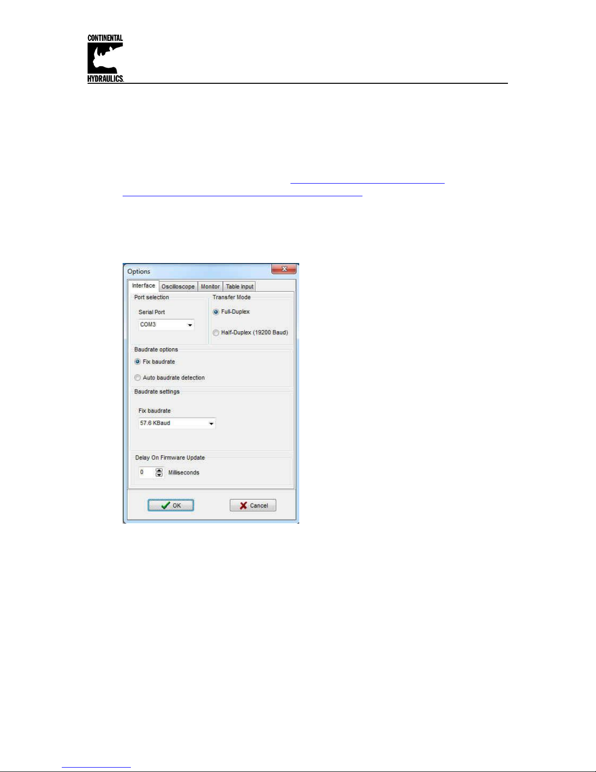
5. Select com port in upper left hand corner of the GUI program.
6. Open the Options Tab and verify that the correct com port, full Duplex and 57.6K Baud
rates are selected.
7. Connect with the CEM by selecting the connect button.
8. Click on the ID Button.
9. Adjust CURRENT parameter to match the nominal solenoid current.
10. Adjust dither amplitude, DAMPL, and dither frequency, DFREQ, to optimize performance
of valve.
11. Set the SIGNAL type to voltage (0-10V) or current (4-20ma). See ANIMODE if the
signals are other than standard. Some scaling may be required.
12. Set the MIN, MAX, and TRIGGER, for the desired system output.
13. Adjust the SYS_RANGE to the pressure output of the valve at rated current. For
example, the Continental model VER03M-210-A-K1-24D is rated for 210 bar. Set the
SYS_RANGE X to 210. The units on this parameter is bar.
Page 4 of 24 CEM-PA-B CHI 1020688 01/2016
Page 5

Continental Hydraulics Installation Manual
14. Set the N_RANGE:X to the maximum pressure rating of the pressure sensor. For a 0210 bar pressure transducer, set N_RANGE:X to 210 bar. This setting should be the
same or greater than the SYS_RANGE value.
15. Use the OFFSET:X to compensate for the pressure transducer reading at actual 0bar
pressure.
16. Adjust RAMP as required.
17. Set internal monitor function, SENS, as required.
18. Adjust PID error correction parameters, (C:P, C:I, C:D, C:D_TI, C:FF), to tune the
system performance.
Module Mounting Location:
This module is to be mounted in a cabinet for protection from the local environment.
Ensure there is adequate free space around the module to allow for cooling air flow.
This module is designed to snap onto an industry standard 35mm DIN rail.
Do not mount near other modules that emit high power electrical interference, such as
motor controllers and high power contactors.
Power Supply:
This module is designed to operate on DC power from a regulated power supply ranging
from 12 to 30 volts. Match valve solenoid voltage rating to power supply, typically 12 or
24 volts. A 3 amp medium action fuse is recommended in the “+” power supply line.
Wiring to Valve:
Two conductors are required for each solenoid. There is no need for shielding on these
power conductors.
Wire size is chosen to provide an acceptable voltage drop between the module and the
valve solenoid. The following chart is based on 5% drop for 12v and 24v applications.
The listed cable length is distance from module to valve, and includes the voltage drop
of the return conductor.
Wire size 2.6A 12v 1.6A 24v 0.86A 24v
12 gauge 66 ft. max 215 ft. max 400 ft. max
14 gauge 49 ft. max 159 ft. max 295 ft. max
16 gauge 31 ft. max 100 ft. max 186 ft. max
18 gauge 19 ft. max 63 ft. max 117 ft. max
20 gauge 13 ft. max 39 ft. max 73 ft. max
22 gauge 8 ft. max 25 ft. max 46 ft. max
All analog input signal cables must be shielded!
Good analog system design requires that all analog signals in an electrically noisy
environment be shielded. Long wires act like antennas that pick up analog noise. The
wire connecting the analog command source to command this module must be shielded!
Shielding a noise sensitive wire is accomplished by wrapping a noise blocking foil or
braided shield around the signal wire. This shield must be grounded at only one end,
usually the end that sends the signal. A control cable may have many individual
conductors. The conductors may be shielded individually, or may be shielded as a
group. Short signal wires in electrically quiet environments may not need to be shielded.
The CEM family of modules all have an internal ground connection to the DIN rail. For
this module ground to be effective, please insure the DIN rail is properly grounded.
Page 5 of 24 CEM-PA-B CHI 1020688 01/2016
Page 6
Continental Hydraulics Installation Manual
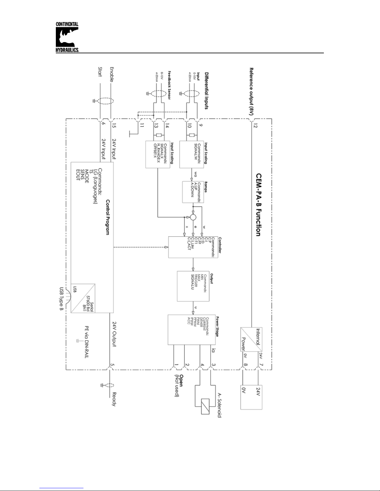
Circuit Diagram
Page 6 of 24 CEM-PA-B CHI 1020688 01/2016
Page 7
Continental Hydraulics Installation Manual
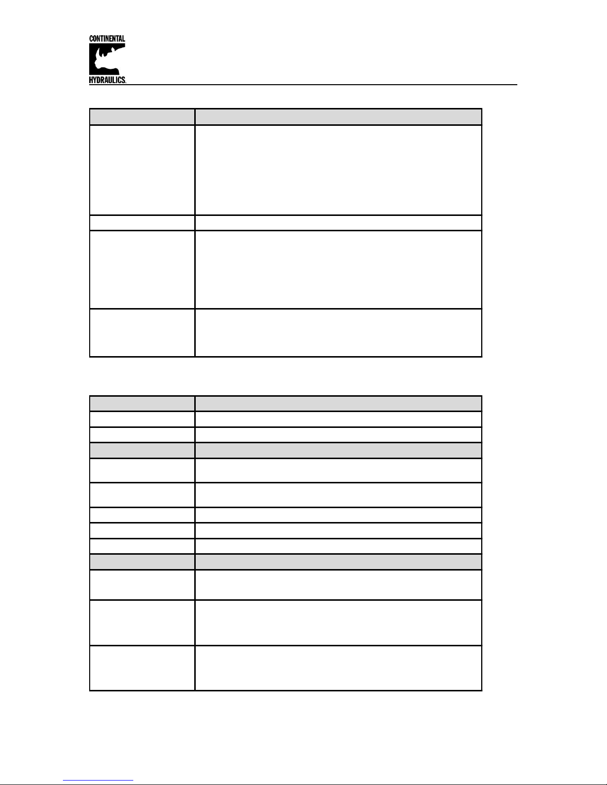
LED Definitions
LEDs Description of the LED function
Identical to the READY output.
OFF: No power supply or ENABLE is not activated
ON: System is ready for peration
Flashing: Error discovered
Only active when SENS = ON
YELLOW A
Intensity of the solenoid current
1. Chasing light (over all LEDs): The bootloader is active. No
normal functions are possible.
2. All LEDs flash shortly every 6 s: An internal data error was
detected and corrected automatically! The module still works
regularly. To acknowledge the error the module has to be cycle
powered.
YELLOW A +
YELLOW B
Both yellow LEDs flash oppositely every 1 s: The nonvolatile stored
parameters are inconsistent! To acknowledge the error, data has to
be saved with the SAVE command or the corresponding button in the
CHI-PC.
GREEN
GREEN + YELLOW A
Terminal Identification - Input and output signals
Connection Supply
PIN 7 Power supply (see technical data)
PIN 8 0 V (GND) connection.
Connection Analogue signals
PIN 9 / 10
Pressure com m and value (WA), signal range 0… 10 V or 4… 20 mA,
scalable (SIGNAL W)
PIN 13 /14
Pressure feedback value (X), signal range 0… 10 V or 4… 20 mA,
scalable (SIGNAL X)
PIN 11 0 V (GND) connection for analogue signals
PIN 12 8V reference voltage output
PIN 3 / 4 PWM output to the solenoid
Connection Digital inputs and outputs
Enable input:
Generally enabling of the application.
RUN (Start) Input:
ON: The controller is active.
OFF: The controller is not active.
READY output:
ON: The module is enabled; there are no discernable errors.
OFF: ENABLE (PIN 15) is not active or an error has been detected.
PIN 15
PIN 6
PIN 5
Page 7 of 24 CEM-PA-B CHI 1020688 01/2016
Page 8
Continental Hydraulics Installation Manual
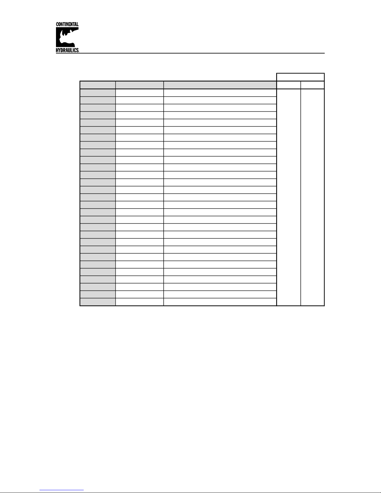
CEM-PA-B Function Parameter layout
Ref Page Command Parameter Help / Description STD EXP
9 LG EN EN English X X
9 MODE EXP Standard / Expert mode X X
9 SENS AUTO Malfunction monitoring [ON / OFF /AUTO] X X
10 EOUT 0 Output signal if not ready [0.01%] X
10 SYS_RANGE 100 System pressure [bar] X X
10 SIGNAL:X U0-10 Type of Input X X
13 N_RANGE:X 100 Sensor nominal pressure [bar] X X
13 OFFSET:X 0 Sensor offset [mbar] X X
10 SIGNAL:W U0-10 Type of Input X X
14 RA:UP 100 Command signal ramp time [ms] X X
14 RA:DOWN 100 Command signal ramp time [ms] X X
15 C:P 50 P gain [x 0.01] x X
15 C:I 4000 I gain [0.01ms] X X
15 C:D 0 D gain [0.1ms] X X
15 C:D_T1 500 D gain filter [0.1ms] x X
15 C:FF 8000 Feed forward [0.01%] X X
16 C:I_LIM 2500 Integrator limitation [0.01%] X X
16 C:I_ACT 2500 Integrator activation threshold [0.01%] X X
17 MIN 0 Deadband compensation [0.01%] X X
17 MAX 10000 Output Scaling [0.01%] X X
17 TRIGGER 200 Trigger point of the MIN function in 0.01% X X
18 SIGNAL:U + Output polarity X X
18 CURRENT 1000 Rated solenoid current [mA] X X
18 DFREQ 121 Dither frequency [Hz] X X
18 DAMPL 500 Dither amplitude [0.01%] X X
19 PWM 2604 PWM frequency [Hz] X X
19 ACC ON Auto Adjustment of the current loop [OFF / ON] X
20 PPWM 7 P-Gain of the current loop X
20 IPWM 40 I-Gain of the current loop X
MODE
Page 8 of 24 CEM-PA-B CHI 1020688 01/2016
Page 9

Continental Hydraulics Installation Manual
Command
Parameters
Unit
Group
LG x
x= DE|EN
-
STD
Command
Parameters
Unit
Group
MODE x
x= STD|EXP
-
STD
Command
Parameters
Unit
Group
SENS x
x= ON|OFF|AUTO
-
STD
Command Parameter Descriptions
LG (Changing the language)
Either English or German can be selected for the help texts.
After changing the language settings, the ID button in the menu bar (CHI-PC) must be
pressed (module identification).
MODE (Parameter view)
This command changes the operating mode. Various commands (defined via STD/EXP)
are blanked out in Standard Mode. The commands in Expert Mode have a more
significant influence on system behavior and should accordingly be changed with care.
SENS (Malfunction monitor)
This command is used to activate/deactivate the monitoring functions (4… 20 mA
sensors, output current, signal range and internal failures) of the module.
ON: All monitoring functions are active. Detected failures can be reset by
deactivating the ENABLE input.
OFF: No monitoring function is active.
AUTO: Auto reset mode. All monitoring functions are active. If the failure doesn’t exist
anymore, the module automatically resumes to work.
Normally the monitoring functions are always active because otherwise no
errors are detectable via the READY output. Deactivating is possible mainly
for troubleshooting.
Page 9 of 24 CEM-PA-B CHI 1020688 01/2016
Page 10

Continental Hydraulics Installation Manual
Command
Parameters
Unit
Group
EOUT X
x= -10000… 10000
0.01 %
EXP
Command
Parameters
Unit
Group
SYS_RANGE X
x= 10… 1000
bar
STD
Command
Parameters
Unit
Group
SIGNAL:I X
i= W|X
x= OFF|U0-10|I4-20
-
EASY
EOUT (Output signal if not ready)
Output value in case of a detected error or a deactive ENABLE input. A value (degree of
valve opening) for use in the event of a sensor error (or the module is disabled) can be
defined here. This function can be used if, for example, the drive is to move to one of the
two end positions (at the specified speed) in case of a sensor error.
|EOUT| = 0 The output is switched off in the event of an error. This is normal behavior.
The output value defined here is stored permanently (independently of the parameter
set). The effects should be analyzed by the user for each application from the point of
view of safety.
SYS_RANGE (System pressure)
This command defines the maximum pressure of the selected valve at rated current
applied, which corresponds to 100 % of the input signal. If the demand is set incorrectly,
this leads to incorrect system settings, and the dependent parameters cannot be
calculated correctly.
SIGNAL (Type of input signal)
This command can be used to change the type of input signal (voltages or current) and
to define the direction of the signal. This command is available for all analogue inputs (W
and X).
OFF= Deactivation of the input
See ANIMODE section if the signals used are not listed above, for re-scaling as required.
Page 10 of 24 CEM-PA-B CHI 1020688 01/2016
Page 11

Continental Hydraulics Installation Manual
AINMODE
The AINMODE is used to define the type of analog input signals being used.
The standard default setting of AINMODE is EASY. In the EASY mode the SIGNAL:W/X/V (see
page 13) are only available in the most commom 0-10 volt or 4-20mA values.
If the input signal being used are not as listed, the AINMODE is available in the MATH mode
where the input signals can be scaled by a linear equation.
To enter the MATH option, you must change the AINMODE to MATH by use of the Terminal
Window. (see steps 1-4 below)
Once in the Termainal Window screen type in AINMODE MATH (ENTER), and click the Save
button. At this time you may go back to the Parameter screen where you can use the user
defined scalling feature.
Once in the MATH mode you will be able to scale the various input signals as shown below.
Page 11 of 24 CEM-PA-B CHI 1020688 01/2016
Page 12

Continental Hydraulics Installation Manual
Command
Parameters
Unit
Group
FUNCTION
AIN:I a b c x
i = A|B
a= -10000… 10000
b= -10000… 10000
c= -10000… 10000
x= V|C
-
-
-
0.01%
-
EXP
AA
A-B
Command
Input
Description
AIN:X 1000 1000 0 V
0… 10 V
Range: 0… 100 %
AIN:X 10 8 1000 V OR
AIN:X 1000 800 1000 V
1… 9 V
Range: 0… 100 %; 1 V = 1000 used for the offset and
gained by 10 / 8 (10 V divided by 8 V (9 V -1 V))
AIN:X 10 4 500 V OR
AIN:X 1000 400 500 V
0.5… 4.5 V
Range: 0… 100 %; 0.5 V = 500 used for the offset and
gained by 10 / 4 (10 V divided by 4 V (4.5 V -0.5 V))
AIN:X 20 16 2000 C OR
AIN:X 2000 1600 2000 C OR
AIN:X 1250 1000 2000 C
4… 20mA
Range: 0… 100 %
The offset will be compensated on 20 % (4 mA) and the
signal (16 mA = 20 mA – 4 mA) will be gained to 100 %
(20 mA).
Each of this parameterization for 4… 20 mA is setting the
range to 0… 100 %.
AINMODE - Analogue input scaling parameters
This command offers an individual scalable input. The following linear equation is used for the
scaling.
Output = A/B ∙ (Input – C)
The “C” value is the offset (e.g. to compensate the 4 mA in case of a 4… 20 mA input signal).
The variables A and B are defining the gain factor with which the signal range is scaled up to
100 % (e.g. 1.25 if using 4… 20mA input signal, defined in default current settings by A = 1250
and B = 1000). The internal shunt for the current input signal is activated when parameters AIN:A
and AIN:B are set to Current (X=C).
The gain factor is calculated by dividing total input signal range (A) by the actual input range (B).
In the case of a 4-20mA with a single solenoid valve, the total range is 0-20mA, which means
A=20. The actual range is 4-20 mA, therefore, B= (20-4) =16. An offset, C, must be added to
compensate for the 0-4mA not being used of the full range. The offset is 4mA/20mA=0.2 or 20%.
Therefore C=2000 since the unit value for C is 0.01%.
Shown in the below table are the most common input command signal and the corresponding
settings to be used.
Typical settings (examples):
Page 12 of 24 CEM-PA-B CHI 1020688 01/2016
Page 13

Continental Hydraulics Installation Manual
Command
Parameter
Unit
Group
N_RANGE:X X
x= 10… 10000
bar
EASY
Command
Parameter
Unit
Group
OFFSET:X X
x= -60000… 60000
mbar
EASY
N_RANGE:X (Sensor nominal pressure)
N_RANGE (nominal range) is used to define the pressure range of the sensor. This
value should be always same as or higher than SYS_RANGE. The control parameter
cannot be calculated correctly in case of wrong values.
OFFSET:X (Sensor offset)
Adjustment of the zero point of the sensor. If the command signal and feedback signals
are not zeroed to each other this offset should be used.
Using of the commands SYS_RANGE, N_RANGE:X and OFFSET:X
Example of use:
With these commands, the feedback sensor is scaled. Suppose you have a pressure
control with the following characteristics:
The system pressure is 350 bar
The pressure sensor has a 4-20mA current output
The nominal pressure of the sensor is 600bar (20mA at 600bar)
The sensor has an offset of 3bar (at 0bar real pressure 3bar is displayed)
To scale this sensor correctly the following settings should be made:
SYS_RANGE 350 bar
SIGNAL:X I4-20
N_RANGE:X 600 bar
OFFSET:X -3000 mbar
Page 13 of 24 CEM-PA-B CHI 1020688 01/2016
Page 14

Continental Hydraulics Installation Manual
Command
Parameter
Unit
Group
RA:I X
i= UP|DOWN
x= 1… 600000
ms
STD
t
Ausgang/Output A
A:UP
A:DOWN
RA (Command signal ramp time)
Two quadrant ramp function.
The ramp time is separately set for UP and DOWN ramps.
Page 14 of 24 CEM-PA-B CHI 1020688 01/2016
Page 15

Continental Hydraulics Installation Manual
Command
Parameter
Unit
Group
C:I X
I= P|I|D|D_T1|FF
:P x= 0… 10000
:I x= 0… 30000
:D x= 0… 1200
:D_T1 x= 0… 1000
:FF x= 0… 10000
0.01
0.1 ms
0.1 ms
0.1 ms
0.01 %
STD
C:P, C:I, C:D C:D_TI, C:FF Control parameters (PID controller)
The control function will be parameterized via this command.
The C:P, I and D gain are similar to a standard PID controller.
The T1 factor is used for the D-gain in order to suppress high-frequency noise.
The FF value is a forward control value to control the output by the input signal directly.
The PID closed loop control function has only to adjust the difference (the error).
Value 0 deactivates the integrator.
Page 15 of 24 CEM-PA-B CHI 1020688 01/2016
Page 16

Continental Hydraulics Installation Manual
Command
Parameter
Unit
Group
C:I_LIM X
C:I_ACT X
x= 0… 10000
x= 0… 10000
0.01 %
0.01 %
STD
C:I_LIM, C:I_ACT Integrator control function
The integrator function is controlled by this command.
C:I_LIM Limitation of the integrator range (faster control function by reduced pressure
overshoots). By a high nonlinearity of the valve the LIM value must be
sufficient to compensate it.
C:I_ACT Controls the integrator function. To reduce pressure overshoots, an activation
point for the integrator can be programmed via the (I_ACT) value. The
integrator is activated if the actual pressure is higher than the programmed
threshold:
Page 16 of 24 CEM-PA-B CHI 1020688 01/2016
Page 17

Continental Hydraulics Installation Manual
Command
Parameters
Unit
Group
MIN:I X
MAX:I X
TRIGGER X
x= 0… 6000
x= 3000… 10000
x= 0… 3000
0.01 %
0.01 %
0,01 %
STD
1
Eingang / Input
100%
10V
Ausgang / Output
MAX
MIN
TRIGGER
MIN (Deadband compensation)
MAX (Output scaling)
TRIGGER (Response threshold for the MIN parameter)
With this command, the output signal is adjusted to the valve characteristics. With the
MAX value the output signal (the maximum valve current) will be defined. With the MIN
value the overlap (dead band of the valve) will be compensated. Via the TRIGGER the
activation point of the MIN function is set and so a non-sensitive range around the zeropoint1 can be specified.
If the MIN value is set too high, it influences the minimal pressure, which cannot be
adjusted any longer. In extreme case this causes to an oscillating at small input values.
This dead band is necessary, in order to avoid unrequested activations caused by small variations of the
input signal. If this module is used in pressure controls, the TRIGGER value should be reduced (typical:
1…10).
Page 17 of 24 CEM-PA-B CHI 1020688 01/2016
Page 18

Continental Hydraulics Installation Manual
Command
Parameter
Unit
Group
SIGNAL:U X
x= + | -
-
EXP
Command
Parameters
Unit
Group
CURRENT X
x= 500… 2600
mA
STD
Command
Parameters
Unit
Group
DFREQ X
DAMPL X
x= 60… 400
x= 0… 3000
Hz
0.01 %
STD
2
3
4
SIGNAL:U (Output polarity)
This command is used to define the output polarity.
+ 0 % to 100 %, normal output
- 100 % to 0 %, changed output polarity
CURRENT (Rated solenoid current)
The nominal output current is set. Dither and also MIN/MAX always refer to this current
range.
DFREQ (Dither frequency) / DAMPL (Dither amplitude)
The dither2 can be defined with this commands. Different amplitudes or frequencies may
be required depending on the valve.
The dither amplitude is defined in % (peak to peak value) of the nominal output current3
(see: CURRENT command).
The dither frequency is defined in Hz. Depending on the internal calculations, the
frequency is adjustable in steps only4.
The PPWM and IPWM parameters influence the effect of the dither setting. These
parameters should not be altered again after the dither has been optimized.
The dither is a ripple signal which is superimposed on the current set point and is defined by the amplitude
and frequency: the dither frequency and the PWM frequency. The dither frequency should not be confused
with the PWM frequency. In some documentations the PWM frequency is described as a dither. This can be
recognized by the lack of the dither amplitude.
The dither amplitude is a command signal. Derivations between the commanded amplitude and the real
amplitude are possible, depending on the dynamic of the solenoid.
The lower the dither frequency, the smaller the steps. Therefore no practical problems are expected.
Page 18 of 24 CEM-PA-B CHI 1020688 01/2016
Page 19

Continental Hydraulics Installation Manual
Command
Parameter
Unit
Group
PWM X
x= 61… 2604
Hz
EXP
Command
Parameter
Unit
Group
ACC X
x= ON|OFF
-
EXP
PWM (PWM Frequency)
The frequency can be changed in defined steps (61 Hz, 72 Hz, 85 Hz, 100 Hz, 120 Hz,
150 Hz, 200 Hz, 269 Hz, 372 Hz, 488 Hz, 624 Hz, 781 Hz, 976 Hz, 1201 Hz, 1420 Hz,
1562 Hz, 1736 Hz, 1953 Hz, 2232 Hz and 2604 Hz). The optimum frequency depends
on the valve.
If the PWM frequency is less than 500 Hz, the dither amplitude DAMPL should be set to
zero.
The PPWM and IPWM parameters should be adapted when using low PWM frequencies
because of the longer dead times which forces a reduced stability of the closed loop
control.
ACC (Current loop auto adjustment)
Operation mode of the closed loop current control.
ON: In automatic mode PPWM and IPWM are calculated depending on the pre-set
PWM-frequency.
OFF: Manual adjustment.
Page 19 of 24 CEM-PA-B CHI 1020688 01/2016
Page 20

Command
Parameters
Unit
Group
PPWM X
IPWM X
x= 0… 30
x= 1… 100
-
-
EXP
Command
Description
Unit
WA
W
X
E
U
IA
Input signal
Command value
Feedback value
Control error
Output
Solenoid current5
mm
mm
mm
mm
%
mA
5
PPWM (P gain of the current loop)
IPWM (I gain of the current loop)
Continental Hydraulics Installation Manual
The PI current controller for the solenoids is parameterized with these commands.
These parameters should not be changed without adequate measurement facilities and
experience.
Attention, if the parameter ACC is set to ON, these adjustments are done automatically.
If the PWM frequency is < 250 Hz, the dynamic of the current controller has to be
decreased.
Typical values are: PPWM = 1… 3 and IPWM = 40… 80.
If the PWM frequency is > 1000 Hz, the default values of PPWM = 7 and IPWM = 40
should be chosen.
PROCESS DATA (Monitoring)
The process data are the variables which can be observed continuously on the
monitor or on the oscilloscope.
The display of the solenoid current (in CHI-PC program) is damped in order to be able to bring out a stable
signal.
Page 20 of 24 CEM-PA-B CHI 1020688 01/2016
Page 21

Continental Hydraulics Installation Manual
Source
Fault
Characteristic
Command signal PIN
9/10
4... 20 mA
Out of range or broken
wire
The output will be switched
off.
Feedback signal PIN 14
4… 20 mA
Out of range or broken
wire
The output will be switched
off.
Solenoids on PIN 3-4
Wrong cabling, broken
wire
The power stage will be
deactivated.
EEPROM
(when switching on)
Data error
The output is deactivated.
The module can only be
activated by saving the
parameters again!
Failure monitoring
Following possible error sources are monitored continuously when SENS =
ON/AUTO:
CAUTION: Take care of the EOUT command. Changes will influence the
behavior.
Page 21 of 24 CEM-PA-B CHI 1020688 01/2016
Page 22

Continental Hydraulics Installation Manual
FAULT
CAUSE / SOLUTION
ENABLE is active, the
module does not respond,
and the READY LED is
off.
There is presumably no power supply or no ENABLE signal (PIN 15) present.
Other faults are signalized with a flashing READY LED.
ENABLE is active, the
READY LED is flashing.
The flashing READY LED signals that a fault is detected by the module. The
fault could be:
A cable breakdown or no signal at the inputs (PIN 9 or PIN 14) if 4… 20
mA signals are parameterized.
A cable breakdown or incorrect cabling to the solenoids (in the P version
only).
Internal data error: press the SAVE button to delete the data error. The
system reloads the DEFAULT data.
With the CHI-PC operating program the fault can be localized directly via the
monitor.
ENABLE is active; the
READY LED is active; no
current to the solenoid (no
pressure-build-up).
To locate errors in the pressure-control-circuit, it is useful to start with the open
loop pressure control (PIN 6 is not activated). In this case the module works
like a power amplifier.
No pressure command input is available or the parameterization is
incorrect. With the CHI-PC tool you can check if a command input is
available. If not, you should check the wiring and/or the command setpoint (in the PLC for example).
If the command input is correct, you have to check the valve control
parameter. If the current is set too low (parameter CURRENT), the output
current and the expected pressure are too low.
Wrong configured pressure sensor (if PIN 6 is active). If the input-scaling
is set to voltage (V) and the pressure sensor supplies a current signal (4...
20mA), the measured pressure value is always high. The output signal to
the valve is therefore low. For further checking: disable PIN 6.
The pressure valve is controlled correctly (the output is going up to the
nominal current). In this case you may have a hydraulic problem or you
are using free-wheeling-diodes in the solenoid plug. Please remove the
free-wheeling-diodes to allow a correct current measurement.
Troubleshooting
It is assumed that the device is in an operable state and there is communication
between the module and the CHI-PC. Furthermore, the valve control parameterization
has been set with the assistance of the valve data sheets.
Page 22 of 24 CEM-PA-B CHI 1020688 01/2016
Page 23

Continental Hydraulics Installation Manual
FAULT
CAUSE / SOLUTION
ENABLE is active, the
READY LED is active and
the pressure is instable.
In many cases you may have a hydraulic problem.
Electrical problems may be:
Electrical noise at the wire of the power supply.
Very long solenoid wiring (> 40 m), disturbance in the current control
loop6.
Unstable current control loop. The adjustments of the PWM-frequency and
the dither (frequency and amplitude) have to be checked carefully. Good
experiences are made with:
a. PWM-frequency = 2600 Hz (higher frequency), the dither has to be
aligned to the valve (amplitude and frequency).
b. PWM-frequency = 100… 400 Hz (lower frequency), the dither
amplitude is set to 0 % (disabled)7.
ENABLE and START
(PIN 6) are active,
READY LED is ON, the
pressure control works,
but the pressure is not
equal to the command
input.
The system works generally, but wrong control loop settings or wrong
adjustment of the input signals cause control errors.
1. The feedback pressure is proportional to the command input pressure, but
the values are too high or too low.
The scaling of the pressure valve is affected by the adjustment of
the output current and the parameter MAX.
The valve has a nominal range of 320 bar and the working
pressure range is 240 bar, the parameter MAX has to be
decreased. Procedure: Deactivate PIN 6, set the command input
to 100 % and adjust the correct pressure by reducing the MAX
parameter.
6
7
Maybe you have to adjust / optimize the solenoid control loop (P and I).
In most applications (particularly pressure-actuated pumps) with pressure valves a lower PWM-frequency
is the better solution.
Page 23 of 24 CEM-PA-B CHI 1020688 01/2016
Page 24

Continental Hydraulics Installation Manual
FAULT
CAUSE / SOLUTION
ENABLE and START
(PIN 6) are active, the
READY LED is active,
the pressure control
loop works, but the
pressure is oscillating or
the pressure UP and
DOWN time is too slow.
The capability of the hydraulic system has to be checked. Deactivate PIN 6 for
open loop control and check the pressure build up and down time. If the system
is in open loop still unstable, check the hydraulic and the dither/ PWM setup
first.
1. Check the parameters C:I, C:P and C:SC.The parameter C:SC has the
following relevance:
With this parameter you can increase or decrease the feed forward gain to
the valve. C:SC 8000 (80 %) means, the remaining 20 % must be provided
by the PID compensator. The integrator limitation should be set to 2500...
3500 (25 % ... 35 %)8.
2. The C:P (P-gain) is to increase in steps9 to the point where the pressure is
going to be unstable. At this point, C:P should be decreased for 30… 50 % to
get an effectual stability margin.
3. The integrator time constant C:I fixes the static error. Typical values are:
100 ms to 1200 ms. Optimize this parameter by monitoring the transient
response.
ENABLE and START
(PIN6) are active, the
READY LED is active,
and the pressure control
loop works, but there
are high errors mainly at
lower or higher
command pressure.
The non-linearity of the valve is higher than the controlling range of the
integrator. The parameter LIM:I should be increased.
ENABLE and START
(PIN 6) are active, the
READY LED is active,
and the pressure control
loop works. Lower
pressure at the
beginning causes that
the system is not
actuated and that no
pressure build-up
occurs.
In this case, the integrator threshold (activation point of the integrator) in
combination with the controller setting is too high. The parameter LIM: S should
be reduced.
8
9
The limit value should be higher than the remaining control range (100 % - C:SC), additionally you have to
add a value to compensate the non-linearity of the valve.
Optimizing in steps is a general description. Our experience: you can change the parameters in steps from
+20 % or rather -20 % for a rough adjustment of the actual value. For a fine adjustment you can select
smaller steps.
Page 24 of 24 CEM-PA-B CHI 1020688 01/2016
 Loading...