

Continental Hydraulics CEM-AA-B Installation Manual
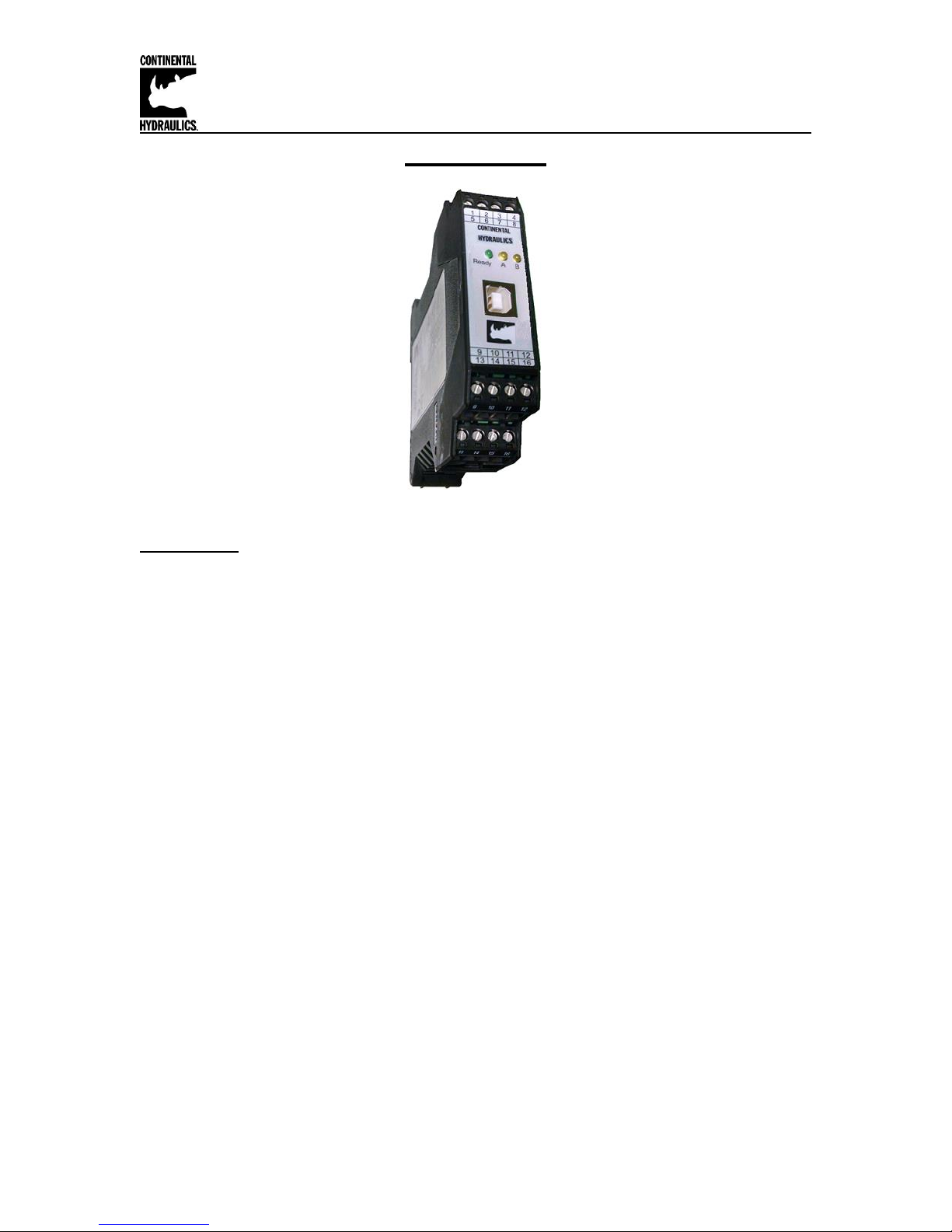
Continental Hydraulics Installation Manual
CEM-AA-B
Description:
This adaptable power amplifier is configurable to drive either single or dual solenoid, or two
independent proportional valve coils up to 2.6A. A wide range of analog or digital signals are
accepted dependent on the configuration. User may select either voltage, current or digital input
mode. These inputs are easily scaled to match system requirements.
The CEM-AA-B module has three selectable function modes:
Function mode AA for operating one single or dual solenoid Proportional Control Valve
Function mode A-B for operating independently two single solenoid Proportional Control
Valves
Function mode RA, This mode accepts 3 independent switch inputs, each which has
independently adjustable speed and ramp controls. Inputs are additive, for up to 8 unique
preset speed and ramp profiles.
Independent Ramp of acceleration and deceleration, IMIN and IMAX, PWM, DITHER settings are
programmable. In addition the valve characteristics can also be linearized via 10 X-Y points per
solenoid output.
The module is disabled if the coil outputs are shorted or open. If command current signal is
outside of the proper range, the module is disabled.
This module is easily adapted to a variety of system requirements. All variables are user adjusted
with easy to use CHI-PC software on your Microsoft Windows laptop. Control variables are
stored in non-volatile memory internal to the module. All variables can be read by the laptop, and
reproduced exactly on other modules.
Page 1 of 33 CEM-AA-B CHI 1020611 01/2016

Continental Hydraulics Installation Manual
Table of Contents
Information Description Page #
Technical Data - All Function Modes for CEM-AA-B …………………….………..…………… 3
LED Indications - All Function Modes …………………………………………………………… 4
Steps to install and configure a new application ……………………….………………………. 5
Module Mounting Location ………………………………………….…………………………….. 6
Power Supply ………………………………………………………………………………….…… 6
Wiring to Valve …………………………………………………………………………………….. 6
Dimensions …………………………………………….…………………………………………… 6
Circuit Diagram Function AA …………………………………………………………………... 7
Terminal Identification AA Function …………………………………………………………….. 8
Parameter List Function AA …………………………………………….………………….… 9
Circuit Diagram Function A-B …………………………………………………………………… 10
Terminal Identification A-B Function …………………………………………………………….. 11
Parameter List Function A-B ………………………………………………….……………… 12
Circuit Diagram Function RA …………………………………………………………………… 13
Terminal Identification RA Function …………………………………………………………….. 14
Parameter List Function RA ……………………………………………………….…………… 15
Command Parameter Descriptions
FUNCTION……………………………………………………………………………..… 16
LG (Language)…………………………………………………………………………… 16
MODE……………………………………………………………………………………... 16
SENS ……………………..……………………………………………………. ………... 17
CCMODE………………………………………………………………………………… 17
SOLENOIDS……………………………………………………………………………... 17
PIN:6………………………………………………………………………………………. 18
USCALE………………………………………………………………………………….. 18
ENABLE_B……………………………………………………………………………….. 18
LIM………………………………………………………………………………………… 19
POL……………………………………………………………………………………….. 20
AINA / AINB………………………………………………………………………………. 20
AIN…………………………………………………………………………………………. 21
AA:I / AB:I (RAMP Time)…………………………………………..………………….... 22
RMODE…………………………………………………………………………………… 23
S:0 – S:7………………………………………………………………………………….. 23
RA:0 – RA:7………………………………………………………………………………. 24
CCA / CCB……………………………………………………………………………..… 25
CC (Characteristics Linearization)…………………………………………………….. 26
MIN………………………………………………………………………………………... 27
MAX……………………………………………………………………………………... 27
TRIGGER………………………………………………………………………………... 27
CURRENT……………………………………………………………………………….. 29
DFREQ…………………………………………………………………………………… 29
DAMPL…………………………………………………………………………………… 29
PWM……………………………………………………………………………………… 30
ACC………………………………………………………………………………………. 30
PPWM / IPWM…………………………………………………………………………… 31
PROCESS DATA (Monitoring)…………………………………………………………………… 32
Failure Monitoring………………………………………………………………………………….. 33
Troubleshooting…………………………………………………………………………………….. 33
Page 2 of 33 CEM-AA-B CHI 1020611 01/2016
Continental Hydraulics Installation Manual
Power supply
[VDC]
12… 30 (incl. ripple)
Power consumption max.
[W]
60 (depending on type of solenoid, two solenoids are
active)
External fuse
[A]
3 medium time lag
Reference voltage
[V]
8 (maximum 25 mA)
Digital inputs
[V]
logic 0: < 2
[V]
logic 1: > 10
Input resistance
[kΩ]
25
Digital outputs
[V]
logic 0: < 2
[V]
logic 1: > 12 (50 mA)
Analogue inputs
[V]
±10 / 0… 10; 90 kΩ
[mA]
4...20; 390 Ω
Resolution
[%]
< 0.01
Nominal PWM output current
[mA]
500… 2600; broken wire monitored and short circuit
proof.
PWM frequency
[Hz]
61...2604; adjustable in steps
Sample time (process control)
[ms]
1
Sample time (solenoid current
control)
[ms]
0.125
Interface
USB type B
Virtual COM port driver (CHI-PC):
9600… 57600 Baud (Default = 57600),
1 Stop bit, No parity, No handshake
Housing
Snap On Module EN 50022
Polyamide PA 6.6
Combustibility class V0 (UL94)
Weight
[kg]
0.190
Protection class
IP20
Temperature range
[°C]
-20… 60
Storage temperature
[°C]
-20 …70
Humidity
[%]
<95 (not condensing)
Vibration
-
IEC 60068-2-6 (category C)
Connections
USB type B
4 x 4 pol. screw terminals
PE: direct via DIN rail
EMC
EN 61000-6-2: 8/2005
EN 61000-6-4: 6/2007 ; A1:2011
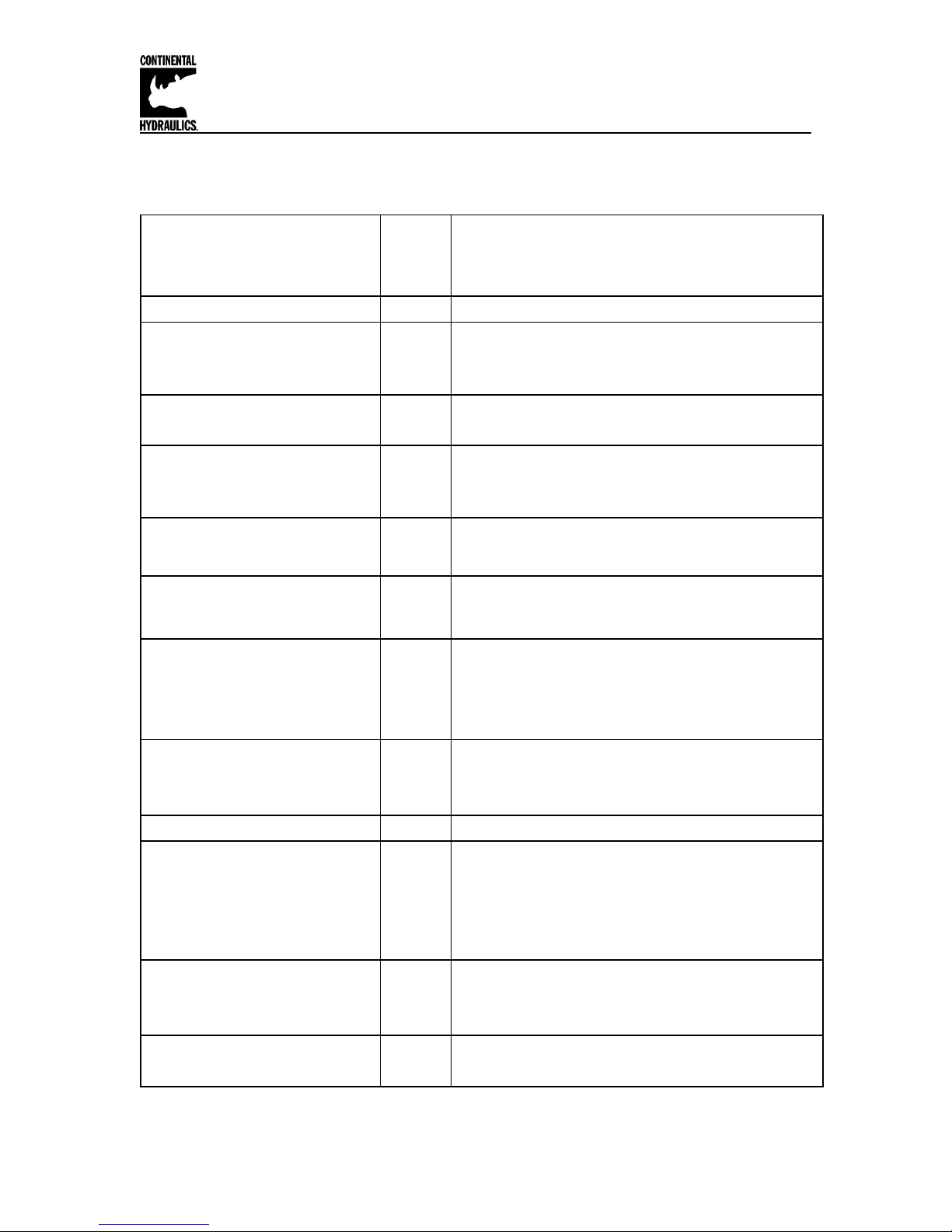
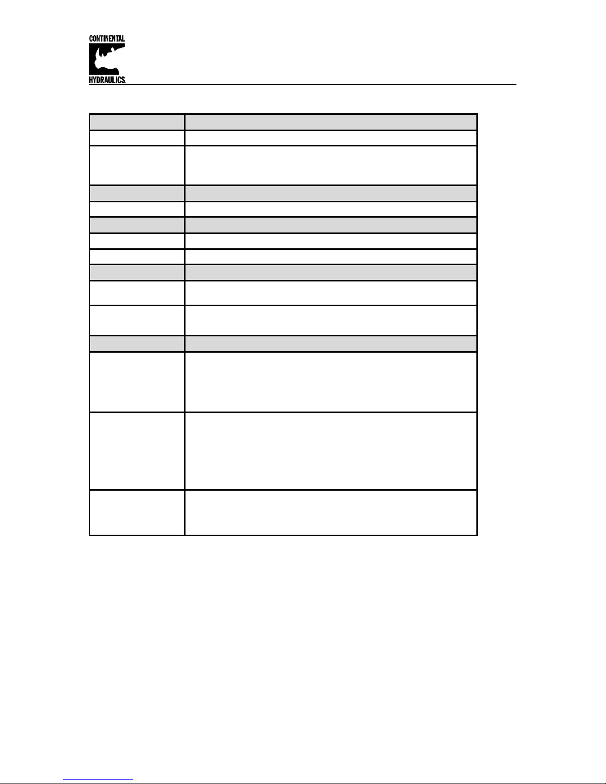
Technical Data - All Function Modes:
Page 3 of 33 CEM-AA-B CHI 1020611 01/2016
Continental Hydraulics Installation Manual
LED's Description of the LED function
1. Chasing light (over all LEDs): The bootloader is active.
No normal functions are possible.
2. All LEDs flash shortly every 6 s: An internal data error was
detected and corrected automatically! The module still works
regularly. To acknowledge the error the module has to have
power cycled.
Yellow + Yellow
Both yellow LEDs flash oppositely every 1 s: The nonvolatile
stored parameters are inconsistent! To acknowledge the error
the data has to be saved with the SAVE command or the
corresponding Function button in the CHI-PC program. If one of
the FUNCTION parameter is changed to an incorrect value, that
parameter value is deleted purposely, and set to default
values. In this case the LEDs indicate no error.
Identical to the READY output.
OFF: No power supply or ENABLE is not activated
ON: System is ready for operation
Flashing: Error detected (e. g. valve solenoid or 4… 20 mA).
Not active when SENS = OFF.
LED in the middle position = Current, Channel A; the intensity
is proportional to the output current
LED in the right position = Current, Channel B; the intensity is
proportional to the output current
GREEN + YELLOW
GREEN
YELLOW
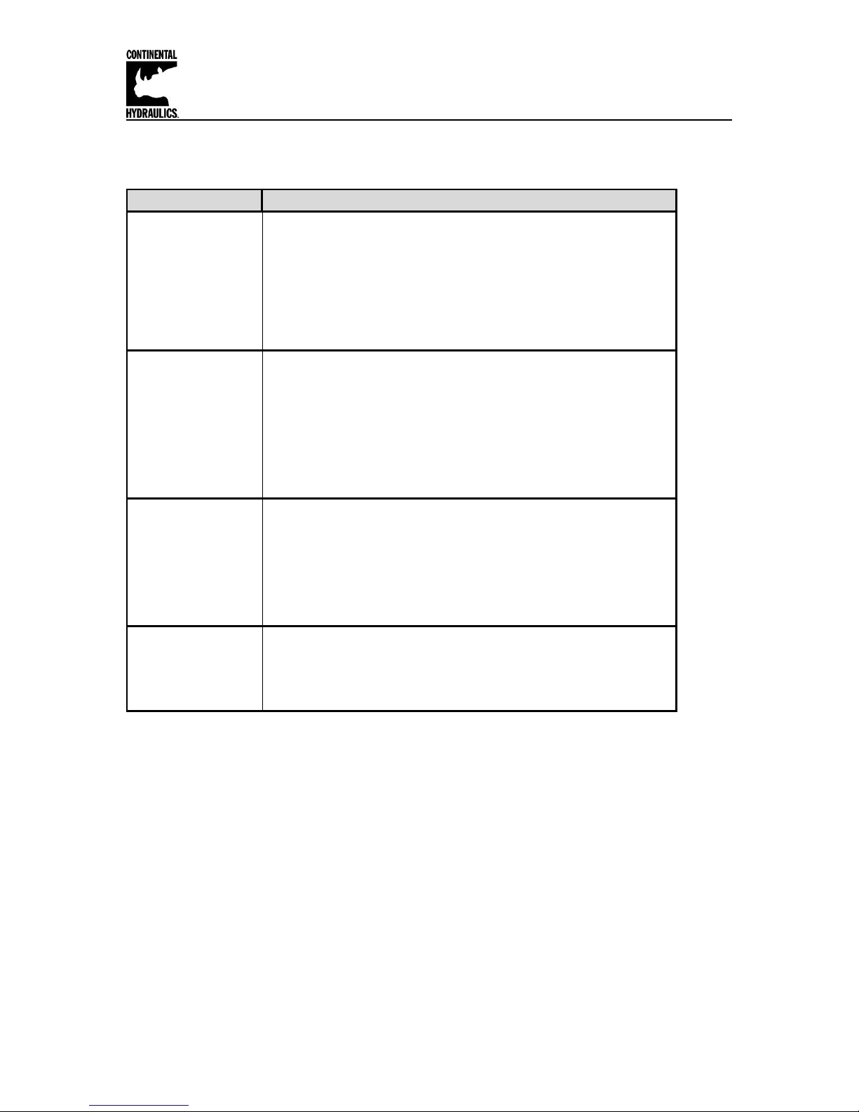
LED Indications - All Function Modes:
Page 4 of 33 CEM-AA-B CHI 1020611 01/2016
Continental Hydraulics Installation Manual
Steps to install and configure a new application:
All parameters are adjusted using VEA-BUSB programming cable and CHI-PC Microsoft
Windows application.
1. Mount the module in a suitable location
2. Connect the power supply and valve solenoids
3. Down load and open the GUI program (www.continentalhydraulics.com/wp-
content/uploads/2015/01/setup-CEWMPC-10-v3.5.0.zip )
4. Connect to Laptop via USB to USB Type B communication cable.
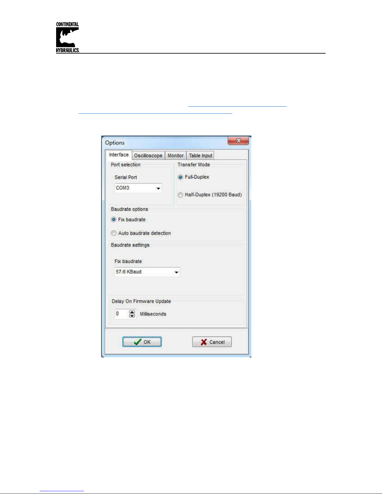
5. Open the Options Tab and in setting, verify that the correct com port, full-Duplex and
57.6K Baud rates are selected.
Page 5 of 33 CEM-AA-B CHI 1020611 01/2016
6. Select Desired Function (AA / A-B / RA) for your application as desired, Click the ID
button to update the Parameter list.
7. Adjust current range to match valve
8. Adjust PWM / Dither to optimize performance of the valve
9. Adjust analog input to voltage or current, and scale input if required.
10. Adjust ramping (if desired)
11. Adjust internal monitor functions (if desired)
12. Adjust current output to the valve for the flow / pressure required (if desired)
Continental Hydraulics Installation Manual
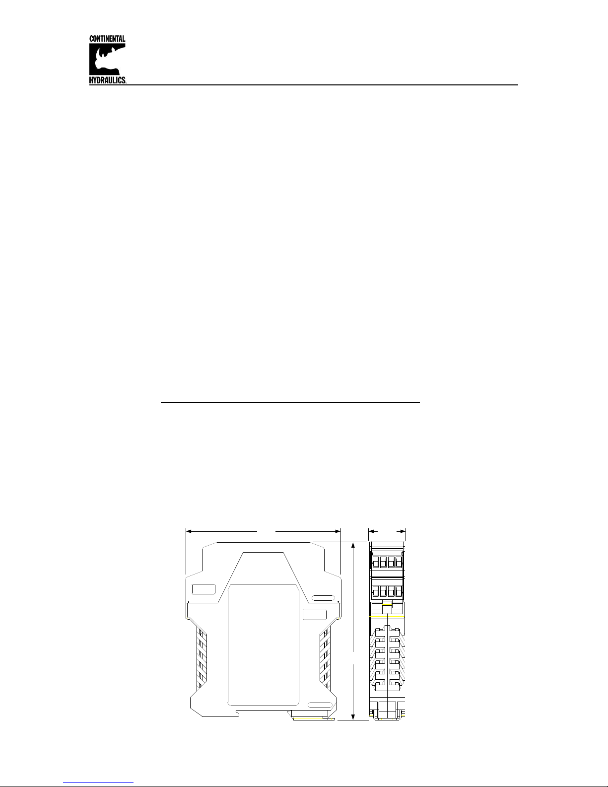
4.5"
3.9"
0.9"
Module Mounting Location:
This module is to be mounted in a cabinet for protection from the local environment.
Ensure there is adequate free space around the module to allow for cooling air flow.
This module is designed to snap onto an industry standard 35mm DIN rail.
Do not mount near other modules that emit high power electrical interference, such as motor
controllers and high power contactors.
Power Supply:
This module is designed to operate on DC power from a regulated power supply ranging from 12
to 30 volts. Match valve solenoid voltage rating to power supply, typically 12 or 24 volts.
A 3 amp medium action fuse is recommended in the “+” power supply line.
Wiring to Valve:
Two conductors are required for each solenoid. There is no need for shielding on these power
conductors.
Wire size is chosen to provide an acceptable voltage drop between the module and the valve
solenoid. The following chart is based on 5% drop for 12v and 24v applications. The listed cable
length is distance from module to valve, and includes the voltage drop of the return conductor.
Wire size 2.6A 12v 1.6A 24v 0.86A 24v
12 gauge 66 ft max 215 ft max 400 ft max
14 gauge 49 ft max 159 ft max 295 ft max
16 gauge 31 ft max 100 ft max 186 ft max
18 gauge 19 ft max 63 ft max 117 ft max
20 gauge 13 ft max 39 ft max 73 ft max
22 gauge 8 ft max 25 ft max 46 ft max
Dimensions:
Page 6 of 33 CEM-AA-B CHI 1020611 01/2016
Continental Hydraulics Installation Manual
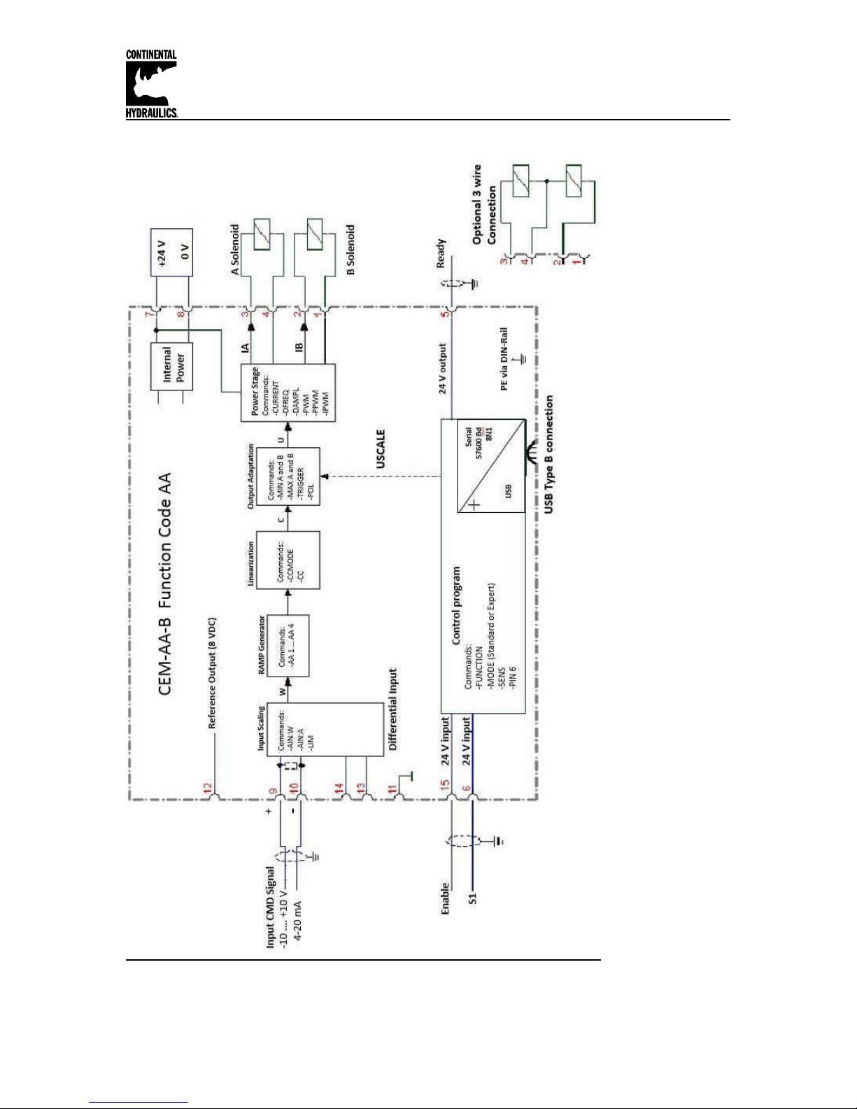
Circuit Diagram Function AA
Page 7 of 33 CEM-AA-B CHI 1020611 01/2016
Continental Hydraulics Installation Manual
Connection Supply
PIN 7
Power supply (see technical data)
0 V (GND) Power supply (ground).
Attention, PIN 8 and PIN 11 are connected internally. PIN 11 is used
as the GND potential for the command and feedback signals..
Connection Reference voltages output
PIN 12
Reference output voltage (8 V).
Connection PWM output
PIN 3 / 4
Current controlled PWM outputs for solenoid A.
PIN 1 / 2
Current controlled PWM outputs for solenoid B.
Connection Analogue input signals
PIN 9 / 10
Com m and (input) signal (W), range -100…100 % corresponds with 10…10 V or 4…20 m A
0 V reference for the signal inputs.
Attention, PIN 8 and PIN 11 are connected internally
Connection Digital inputs and outputs
Enable Input:
This digital input signal initializes the application.
The output and the READY signal will be activated.
By deactivating, error signals are reset.
S1 input:
Function depends on parameter PIN:6 (USCALE/RAMP).
OFF: Output current depends on parameter USCALE; ramp
function is deactivated.
ON: Output current is not scaled by USCALE, ramp function is
activated.
READY output:
ON: Module is ready, no errors are detected
OFF: ENABLE (PIN 15) is deactivated or an error is detected.
CEM-AA-B Function AA Input and Output Terminals
PIN 8
PIN 11
PIN 15
PIN 6
PIN 5
Page 8 of 33 CEM-AA-B CHI 1020611 01/2016
Continental Hydraulics Installation Manual
Ref Page
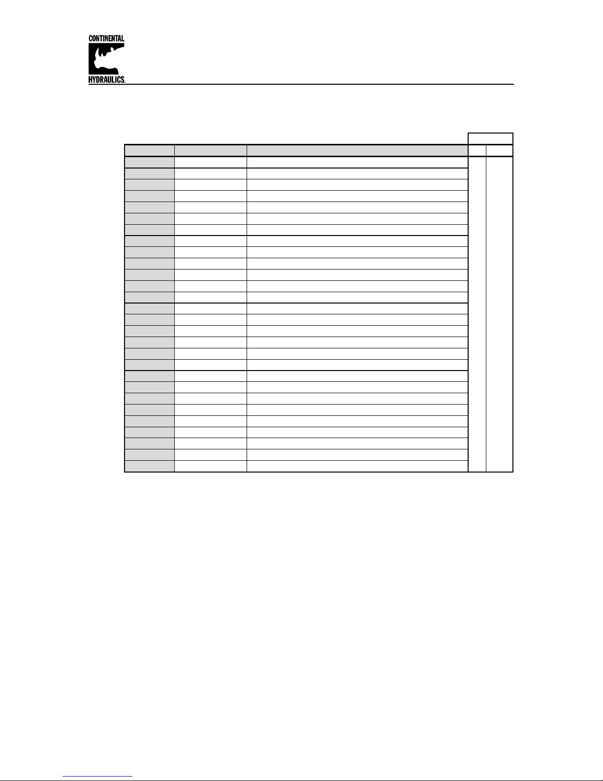
Command Parameter Help / Description STD EXP
16 FUNCTION AA Function mode (AA / A-B / RA) Press ID button after selection X X
16 LG EN EN English X X
16 MODE EXP Standard / Expert mode X X
17 SENS AUTO Malfunction monitoring [ON / OFF /AUTO] X X
17 CCMODE OFF Characteristics linearization [ON / OFF] X
18 PIN:6 USCALE Function of PIN 6 [USCALE / RAMP] X
18 USCALE 10000 Output current scale in 0.01% X
19 LIM 0 Range control input signal in 0.01% X
20 POL + Output polarity (+/-) X X
20 AINA V Input switching, voltage or current [V/C] (Voltage default) X
20 AIN:A 1000 1000 0 V Input scaling via linear equation X
22 AA:1 100 Ramptime acceleration A in ms X X
22 AA:2 100 Ramptime deceleration A in ms X X
22 AA:3 100 Ramptime acceleration B in ms X X
22 AA:4 100 Ramptime deceleration B in ms X X
26 CC characteristic curve Free definable characteristic linearization
27 MIN:A 0 Compensation of the Deadband in 0.01% X X
27 MIN:B 0 Compensation of the Deadband in 0.01% X X
27 MAX:A 10000 Output Scaling in 0.01% X X
27 MAX:B 10000 Output Scaling in 0.01% X X
27 TRIGGER 200 Trigger point of the MIN function in 0.01% X X
29 CURRENT 1000 Rated solenoid current 500…. 2600 mA X X
29 DAMPL 500 Dither amplitude in 0.01% of rated current X X
29 DFREQ 121 Dither frequency in Hz X X
30 PWM 2604 PWM frequency in Hz X
30 ACC ON Auto Adjustment of the current loop [OFF / ON] X
31 PPWM 7 P-Gain of the current loop X
31 IPWM 40 I-Gain of the current loop X
MODE
Parameter List Function AA
Page 9 of 33 CEM-AA-B CHI 1020611 01/2016
Continental Hydraulics Installation Manual
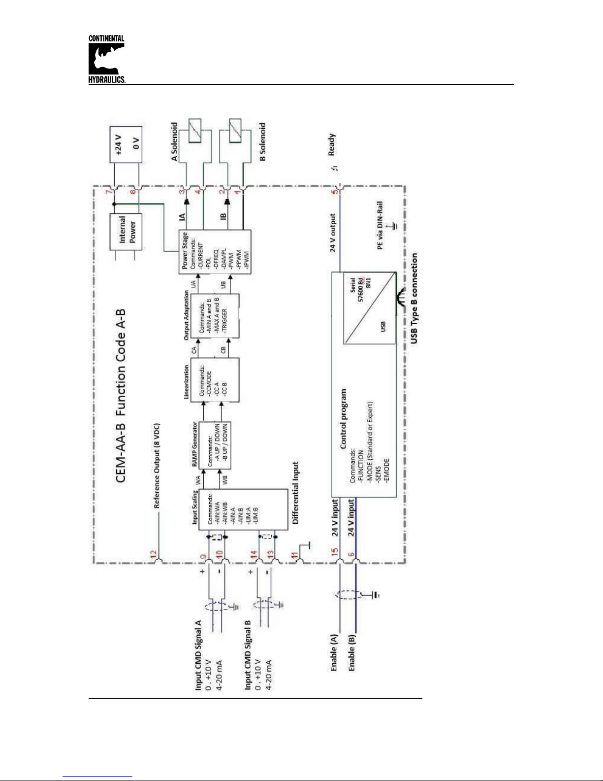
Circuit Diagram Function A-B
Page 10 of 33 CEM-AA-B CHI 1020611 01/2016
 Loading...