

Continental Fireplaces CZ-26 Installation And Operating Instructions Manual
1.11A
SAFETY INFORMATION
If the information in these instructions are not followed exactly, a
fi re or explosion may result causing property damage, personal
injury or death.
Please read entire manual before you install and use your heater.
This heater has not been tested with an unvented gas log set. To
reduce risk of fi re or injury, do not install an unvented gas log set
into the heater.
- This heater can be very hot when burning.
- Combustible materials such as fi rewood, wet clothing, etc. placed too
close can catch fi re.
- Children and pets must be kept from touching the heater when it is
hot.
- The chimney must be sound and free of cracks. Before installing
this unit, contact the local building or fi re authority and follow their
guidelines.
- Operate only with the doors tightly closed.
- Burn wood behind the log retainer directly on the fi rebricks.
- Do not use an elevated grate or otherwise raise the fi re.
- This heater is designed to burn natural wood only. Higher effi ciencies
and lower emissions generally result when burning air dried seasoned
hardwoods, as compared to softwoods or to green or freshly cut
hardwoods.
- Do not start a fi re with chemicals or fl uids such as gasoline, engine
oil, etc.
- Do not burn treated wood, coal, charcoal, coloured paper, cardboard,
solvents or garbage.
- Do not let the heater become hot enough for any part to glow red.
- KEEP STOVE TOP TEMPERATURES BELOW 700°F (371°C). Attempts
to achieve heat output rates that exceed design specifi cations can
result in metal distortion and damage.
INSTALLER: LEAVE THIS MANUAL WITH THE APPLIANCE.
CONSUMER: RETAIN THIS MANUAL FOR FUTURE REFERENCE.
NEVER LEAVE CHILDREN OR OTHER AT RISK INDIVIDUALS ALONE WITH THE APPLIANCE.
INSTALLATION AND
OPERATING INSTRUCTIONS
Wolf Steel Ltd., 24 Napoleon Rd., Barrie, ON, L4M 0G8 Canada /
103 Miller Drive, Crittenden, Kentucky, USA, 41030
Phone (705)721-1212 • Fax (705)722-6031 • www.continentalfi replaces.com • ask@continentalfi re.on.ca
$10.00
!
WARNING
HOT GLASS WILL CAUSE
BURNS.
DO NOT TOUCH GLASS UNTIL
COOLED.
NEVER ALLOW CHILDREN TO
TOUCH GLASS.
!
WARNING
THIS FIREPLACE HAS BEEN TESTED AND LISTED BY INTERTEK TESTING SERVICES TO STANDARDS: CAN/ULC S610, UL 127, FOR ZERO CLEARANCE FIREPLACES, AND TO ULC S639
FOR STEEL LINER ASSEMBLIES FOR SOLID FUEL BURNING MASONRY FIREPLACES. CERTIFIED UNDER USA ENVIRONMENTAL PROTECTION AGENCY (E.P.A.) JULY 1990 AND THE
OREGON DEPARTMENT OF ENVIRONMENTAL QUALITY (D.E.Q.) PARTICULATE EMISSION STANDARDS
CZ-26
1
W415-0893 / B / 08.01.12

2
TABLE OF CONTENTS
1.0 INSTALLATION OVERVIEW 3
2.0 INTRODUCTION 4
2.1 DIMENSIONS 5
2.2 GENERAL INSTRUCTIONS 5
2.3 GENERAL INFORMATION 6
2.3.1 EPA COMPLIANCE 7
2.4 RATING PLATE INFORMATION 7
2.5 HI-EFFICIENCY HEATING 8
3.0 INSTALLATION PLANNING 10
3.1 LOCATION AND CLEARANCES 10
3.2 OUTSIDE COMBUSTION AIR 11
3.3 HEARTH EXTENSION 11
4.0 INSTALLATION 12
4.1 CHIMNEY 13
4.2 TYPICAL CHIMNEY INSTALLATION 14
4.3 ADDING CHIMNEY SECTIONS 15
4.4 OFFSET CHIMNEY INST ALLA TION 16
4.5 INSTALLING FLASHING AND STORM COLLAR 17
4.6 CONNECTION TO A MASONRY CHIMNEY 17
5.0 FRAMING 18
5.1 MINIMUM CLEARANCE TO COMBUSTIBLES 19
5.2 MINIMUM ENCLOSURE CLEARANCES 20
5.3 MINIMUM MANTEL CLEARANCES 22
6.0 FINISHING 23
6.1 DOOR HANDLE INSTALLATION 23
6.2 TOP FIREBOX AND BAFFLE INSTALLATION 23
6.3 LOUVRE INSTALLATION 26
6.4 LOGO INSTALLATION 26
7.0 OPTIONAL INSTALLATION 27
7.1 OPTIONAL BLOWER INSTALLATION 27
7.2 COMBUSTION AIR CONTROL 28
8.0 SELECTING WOOD 29
9.0 OPERATION 30
9.1 OPERATING SOUNDS AND SMELLS 30
9.3 AIR CONTROL 31
9.2 FIRE EXTINGUISHERS AND SMOKE DETECTORS 31
9.4 FUEL LOADING AND BURN CYCLE 32
9.5 STARTING THE FIRE 33
9.6 FLASH FIRES 35
9.7 SMOKING 35
9.8 OVERNIGHT BURN 35
9.9 RE-LOADING THE APPLIANCE 35
10.0 MAINTENANCE 36
10.1 ASH REMOVAL PROCEDURES 36
10.2 CREOSOTE FORMATION AND REMOVAL 36
10.3 RUN-AWAY OR CHIMNEY FIRE 37
10.4 CHIMNEY CLEANING 37
10.5 GLASS REPLACEMENT 37
10.6 CARE OF GLASS 38
10.7 CARE OF PLATED PARTS 38
10.8 GASKET / BAFFLE REPLACEMENT 38
11.0 REPLACEMENTS 39
12.0 TROUBLESHOOTING GUIDE 41
13.0 WARRANTY 42
14.0 SERVICE HISTORY 43
NOTE: Changes, other than editorial, are denoted by a vertical line in the margin.
W415-0893 / B / 08.01.12
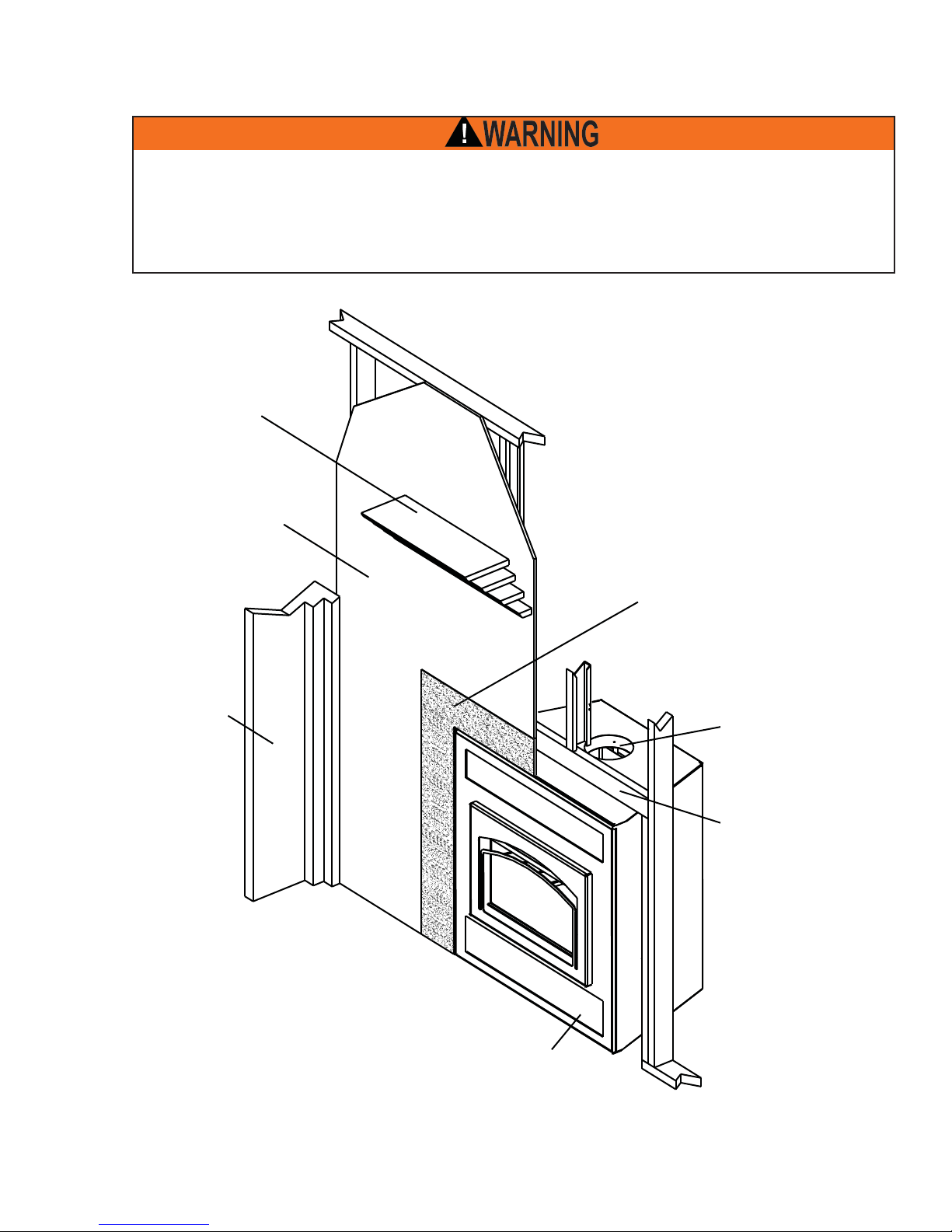
1.0 INSTALLATION OVERVIEW
THIS APPLIANCE AND ITS COMPONENTS ARE DESIGNED TO BE INSTALLED AND OPERATED AS A
SYSTEM. ANY ALTERATION TO OR SUBSTITUTION FOR ITEMS IN THIS SYSTEM, UNLESS ALLOWED
BY THESE INSTALLATION INSTRUCTIONS, WILL VOID THE WARNOCK HERSEY LISTING AND MAY
VOID THE PRODUCT WARRANTY. IT MAY ALSO CREATE A HAZARDOUS INSTALLATION. READ
THROUGH THESE INSTRUCTIONS THOROUGHLY BEFORE STARTING YOUR INSTALLATION AND
FOLLOW THEM CAREFULLY THROUGHOUT YOUR PROJECT.
See the section
“MINIMUM MANTEL
CLEARANCES”
See the sections
“LOCA TION AND
CLEARANCES” for
drywall (or other
combustible material)
3
See the
section
“FRAMING”
Non-combustible material see
the section “FINISHING”
See the section
“CHIMNEY
INSTALLATION”
Side
Wall
See the section
“INSTALLATION /
FRAMING”
Rating Plate, see
“RATING PLATE
INFORMATION”
section.
W415-0893 / B / 08.01.12
4
2.0 INTRODUCTION
• THIS APPLIANCE IS HOT WHEN OPERATED AND CAN CAUSE SEVERE BURNS IF CONTACTED.
• ANY CHANGES OR ALTERATIONS TO THIS APPLIANCE OR ITS CONTROLS CAN BE DANGEROUS AND
IS PROHIBITED.
• Do not operate appliance before reading and understanding operating instructions. Failure to operate appliance
according to operating instructions could cause fi re or injury.
• Before installing this appliance, contact the local building or fi re authority and follow their guidelines.
• This appliance must be installed by a qualifi ed installer.
• Risk of burns. The appliance should be turned off and cooled before servicing.
• Do not operate without fully assembling all components.
• Do not let the appliance become hot enough for any part to glow red.
• Do not install damaged, incomplete or substitute components.
• Risk of cuts and abrasions. Wear protective gloves and safety glasses during installation. Sheet metal edges
may be sharp.
• Children and adults should be alerted to the hazards of high surface temperature and should stay away to avoid
burns or clothing ignition.
• Young children should be carefully supervised when they are in the same room as the appliance. Toddlers,
young children and others may be susceptible to accidental contact burns. A physical barrier is recommended if
there are at risk individuals in the house. To restrict access to an appliance or stove, install an adjustable safety
gate to keep toddlers, young children and other at risk individuals out of the room and away from hot surfaces.
• Clothing or other fl ammable material should not be placed on or near the appliance. Objects placed in front of
the appliance must be kept a minimum of 48” away from the front face of the appliance.
• Due to high temperatures, the appliance should be located out of traffi c and away from furniture and draperies.
• Ensure you have incorporated adequate safety measure to protect infants/toddlers from touching hot surfaces.
• Even after the appliance is out, the glass and/or screen will remain hot for an extended period of time.
• Check with your local hearth specialty dealer for safety screens and hearth guards to protect children from hot
surfaces. These screens and guards must be fastened to the fl oor.
• Any safety screen or guard removed for servicing must be replaced prior to operating the appliance.
• Under no circumstances should this appliance be modifi ed.
• This appliance must not be connected to a chimney fl ue pipe servicing a seperate solid fuel burning appliance.
• Do not operate the appliance with the glass door removed, cracked or broken. Replacement of the glass should
be done by a licensed or qualifi ed service person.
• Do not strike or slam shut the appliance glass door.
• Operate only with the doors tightly closed.
• Only doors / optional fronts certifi ed with the unit are to be installed on the appliance.
• Keep the packaging material out of reach of children and dispose of the material in a safe manner. As with all
plastic bags, these are not toys and should be kept away from children and infants.
• If the appliance is not properly installed, a house fi re may result. Do not expose the appliance to the elements
(ex. rain, etc.) and keep the appliance dry at all times. Wet insulation will produce an odour when the appliance
is used.
• The chimney must be sound and free of cracks. Clean your chimney a minimum of twice a year and as required.
• Do not start a fi re with chemicals or fl uids such as gasoline, engine oil, etc.
• Your appliance requires periodic maintenance and cleaning. Failure to maintain your appliance may lead to
smoke spillage in your home.
• Higher effi ciencies and lower emissions generally result when burning air dried seasoned hardwoods, as
compared to softwoods or too green or freshly cut hardwoods. Burning wet unseasoned wood can cause
excessive creosote accumulation. When this is ignited it can cause a chimney fi re that may result in a serious
house fi re.
• This appliance is designed to burn natural wood only. Do not burn treated wood, coal, charcoal, coloured paper,
cardboard, solvents or garbage.
• Burn wood directly on the fi rebricks. Do not elevate grate or otherwise raise the fi re.
• Do not store wood within appliance installation clearances or within the space required for re-fueling and ash
removal.
• Ashes must be disposed in a metal container with a tight lid and placed on a non-combustible surface well away
from the home or structure until completely cool.
• Ensure clearances to combustibles are maintained when building a mantel or shelves above the appliance.
Elevated temperatures on the wall or in the air above the appliance can cause melting, discolouration or
damage to decorations, a T.V. or other electronic components.
!
WARNING
3.17C
W415-0893 / B / 08.01.12
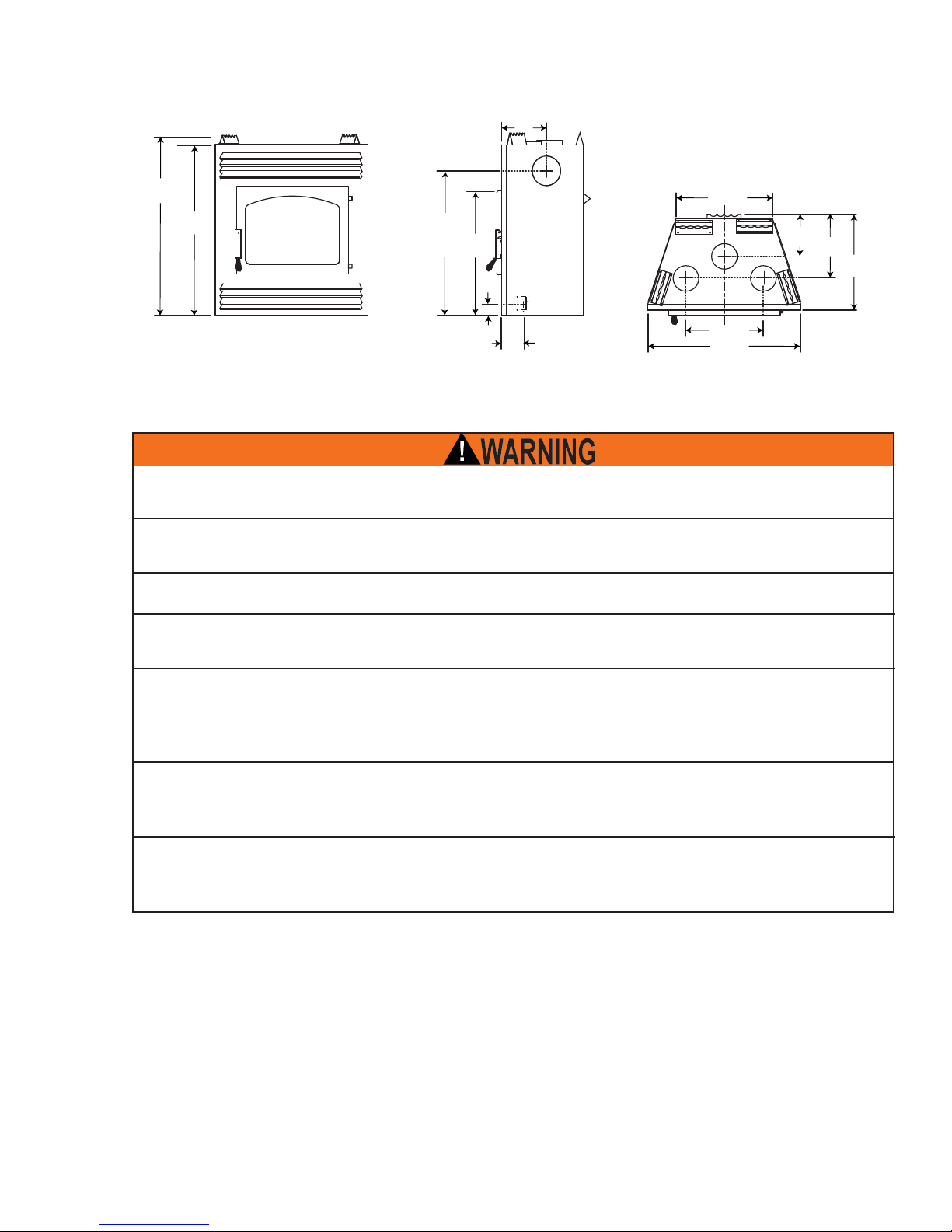
2.1 DIMENSIONS
5
14"
44 1/2"
39 1/2"
2.2 GENERAL INSTRUCTIONS
BEFORE INSTALLING THIS APPLIANCE, CONTACT THE LOCAL BUILDING OR FIRE AUTHORITY AND
THIS APPLIANCE MUST BE INSTALLED BY A QUALIFIED INSTALLER. FOLLOW THE INSTALLATION
DIRECTIONS. DO NOT OPERATE WITHOUT FULLY ASSEMBLING ALL COMPONENTS.
IF THIS APPLIANCE IS NOT PROPERLY INSTALLED, A HOUSE FIRE MAY RESULT.
DO NOT EXPOSE THE APPLIANCE TO THE ELEMENTS (EX. RAIN, ETC.) AND KEEP THE APPLIANCE
DRY AT ALL TIMES. WET INSULATION WILL PRODUCE AN ODOUR WHEN THE APPLIANCE IS USED.
32 1/2"
29 1/2"
5 1/2"
3 1/2"
AIR INLET IS
ON LEFT SIDE
FOLLOW THEIR GUIDELINES.
24 3/4"
19 1/2"
38 1/4"
12"
17 1/2"
25 1/2"
THIS APPLIANCE IS HOT WHEN OPERATED AND CAN CAUSE SEVERE BURNS IF CONTACTED.
CHILDREN AND PETS MUST BE KEPT FROM TOUCHING THE APPLIANCE WHEN IT IS HOT. CON-
TACT YOUR LOCAL AUTHORIZED DEALER / DISTRIBUTOR FOR SAFETY SCREENS THAT MAY BE
AVAILABLE FOR THIS PRODUCT.
COMBUSTIBLE MATERIAL SUCH AS FIREWOOD, WET CLOTHING, ETC. PLACED TOO CLOSE CAN
CATCH FIRE. OBJECTS PLACED IN FRONT OF THE APPLIANCE MUST BE KEPT A MINIMUM OF 48"
FROM THE FRONT OF THE APPLIANCE.
ALL WIRING SHOULD BE DONE BY A QUALIFIED ELECTRICIAN AND SHALL BE IN COMPLIANCE
WITH LOCAL CODES AND WITH THE NATIONAL ELECTRIC CODE ANSI/NF NO. 70-CURRENT (IN THE
UNITED STATES), OR WITH THE CURRENT CSA C22.1 CANADIAN ELECTRIC CODE (IN CANADA).
W415-0893 / B / 08.01.12
6
This is the most effi cient, simple and trouble free wood burning system
we know of and works as follows:
The chimney vent system used on your wood burning appliance should be
designed with the least amount of restriction possible to enable the exhaust
products to easily fl ow through it. Chimney vent systems that are too short
or too long can also have an adverse affect on the fl ow of exhaust through
it. The wood burning appliance and chimney vent system also require a
suffi cient supply of combustion air not only to support the combustion in
the combustion chamber but to replace the exhaust leaving it so it can fl ow
freely up through the vent system and out into the atmosphere. It is the correct balance of combustion air and the chimney vent system that will ensure
the appliance provides you with its optimum performance.
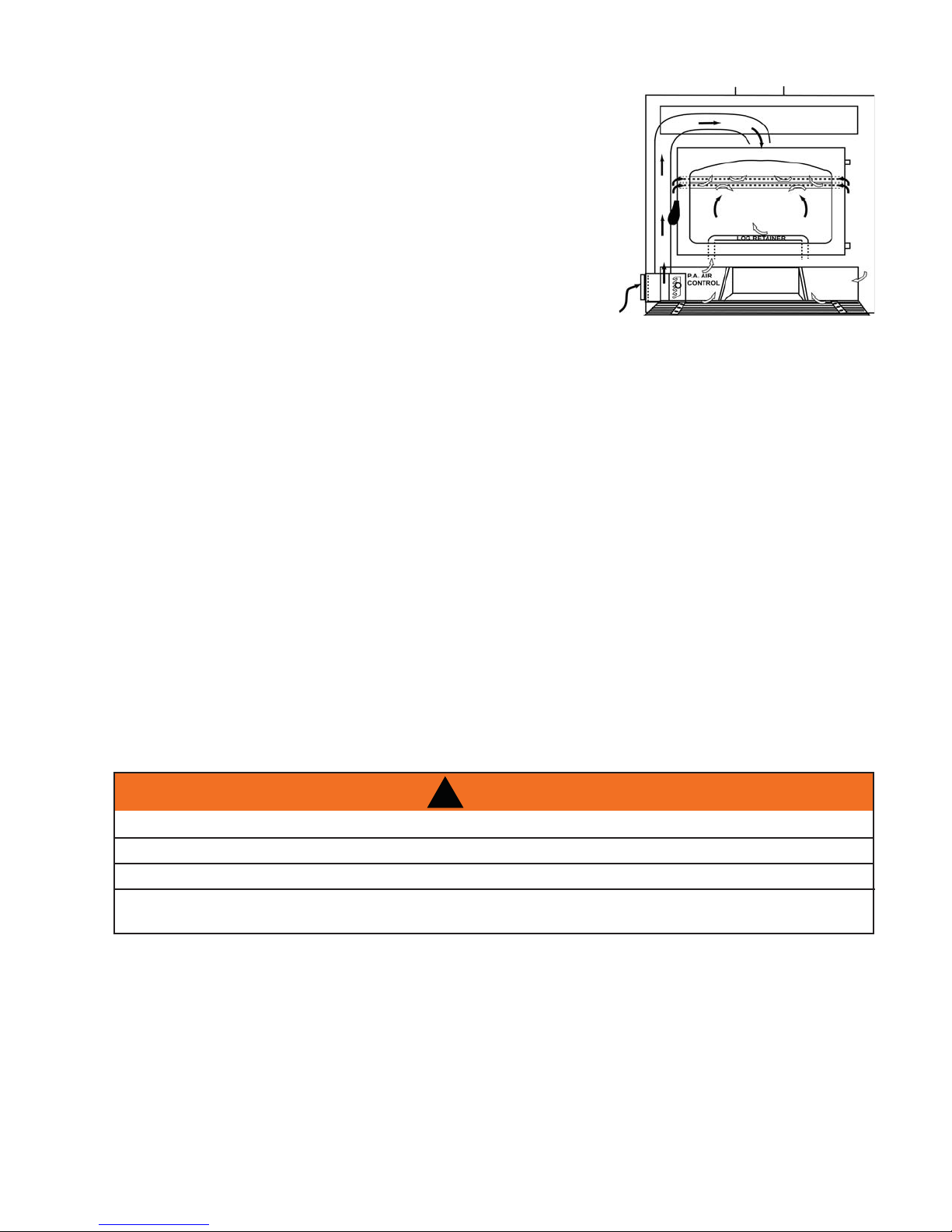
Primary combustion air enters through the air control inlet box regulated by a draft control, travels up the side
through a duct and enters the top centre of the combustion chamber into a preheating airwash located across
the top and then down the window to feed the fi re and also to ensure that the glass remains clean.
Secondary air feeds directly into the combustion chamber at hearth level through the log retainer and also
through inlets located at the bottom back corners of the combustion chamber. This air travels up the riser to the
four secondary air tubes located at the top and shoots out laterally to oxidize the gases rising to the smoke exit.
The combustion chamber is lined with high-temperature fi rebrick on all sides, and across the bottom to main-
tain a high temperature in the combustion chamber so that gases mixing with the preheated air from the
secondary air tubes are easily ignited and burned. The appliance sides and back permit a zero clearance
installation and direct the heat upwards and forwards into the room. Be sure to provide suffi cient combustion
air. There are many other appliances in your home competing for air such as a kitchen range hood, forced air
heating devices or a bathroom exhaust fan.
If the outside air feature is utilized, you will never experience a shortage of combustion air. If you choose not to
utilize outside air and experience draft or smoking problems, you may need to open a door or window.
After extended periods of non-operation such as following a vacation or a warm weather season, the appliance
may emit a slight odour for a few hours. This is caused by dust particles on the fi rebox burning off. Open a
window to suffi ciently ventilate the room.
2.3 GENERAL INFORMATION
DO NOT USE MAKESHIFT COMPROMISES DURING INST ALLATION.
DO NOT BLOCK OR RESTRICT AIR, GRILLE OR LOUVRE OPENINGS.
BURNING YOUR APPLIANCE WITH THE DOOR OPEN OR AJAR CREATES A FIRE HAZARD THAT MAY
RESULT IN A HOUSE AND/OR CHIMNEY FIRE.
All venting connections must be in compliance with the chimney manufacturers installation instructions.
Clearances referred to throughout this manual are the minimum requirements.
Expansion / contraction noises during heating up and cooling down cycles are normal and to be expected.
It is recommended that in all cases, the appliance be secured to the fl oor. Use the pallet packing brackets to
accomplish this.
Mobile home installation requires that the appliance be secured to the fl oor. It is recommended that in all
cases, the appliance be secured to the fl oor. Use the pallet packing brackets to accomplish this.
!
WARNING
DO NOT ADD A HOOD.
W415-0893 / B / 08.01.12
2.3.1 EPA COMPLIANCE
305MM (12")305MM (12")
152MM (6")152MM (6"
N/A N/A
CTIONS)NS)
PAINTED FACE OF THE UNIT. D FACE OF THE UNIT.
(3/8") MIN. THICK MILLBOARD O
LACE OPENING OF 203MM (8
FIRE.
CHIMNEY REQUIREMENTSEQUIREMENT
CHIMNEY MUST BE CEUST BE CE
ULC S610 OR ULC ULC S610 OR ULC
S
STATES.
MASONRY CHMASONRY CH
STAINLESSSTAINLES
OR UL 1R UL
CER
DO NOT TOUCH.
CALIFORNIA PROP 65 WARNING:
Use of this product may produce smoke which contains
chemicals known to the State of California to cause cancer, birth defects, or other reproductive harm.
Y our appliance must be installed in accordance with all national and local building code standards and the standard
of Chimney and Appliances, V ents and Solid
Fuel Burning Appliances NFP A #21 1. Consult the authority having jurisdiction (such as municipal building
department, fi re department, fi re prevention bureau, etc.) to determine the need to obtain a permit. If you are in
doubt about the proper installation for your situation, contact your dealer or local building or fi re offi cial. The
manufacturer does not guarantee that this appliance and its options will completely heat your entire home.
2.4 RATING PLATE INFORMATION
REFER TO FIREPLACE AND CHIMNEY MANUFACTURER'S INSTRUCTIONS AND BUILDING CODE FOR SAFE INSTALLATION AND
OPERATION. DO NOT OBSTRUCT COMBUSTION AIR INLET. OPERATE ONLY WITH VIEWING DOOR CLOSED AND LATCHED. OPERATE ONLY
WITH FIREBRICK IN PLACE. MODEL NZ-26 ONLY: SUITABLE FOR INSTALLATION IN A MOBILE HOME (USA ONLY)
9700539 (WSL)
4001657 (NGZ)
4001658 (NAC)
4001659 (WUSA)
MINIMUM CLEARANCE TO COMBUSTIBLES (BOTH UNITS)
"A": MINIMUM OUTLET AREA (PER CHANNEL) 324SQ CM (50"SQ)
"B": DO NOT BLOCK GRILLS
"C": SIDEWALL 533MM (21")
NZ-26 ONLY:
FRAMING MATERIALS: TOP, SIDES AND BACK: PER STAND-OFF SPACERS.
FINISHING MATERIALS: SEE INSTALLATION MANUAL.
NZ-26WI ONLY:
FRAMING MATERIALS: BACK: PER STAND-OFF SPACER. TOP & SIDES: SEE INSTALLATION MANUAL.
FINISHING MATERIALS: SEE INSTALLATION MANUAL.
BASE OF UNIT TO CEILING: NZ-26 NZ-26WI
VENTED ENCLOSURE: 1,828MM (72”) 2,133MM (84”)
NON-VENTED ENCLOSURE: 2,133MM (84”) N/A
A 51MM (2") WIDE MANTEL MUST BE LOCATED MINIMUM 610MM (24") ABOVE FIREPLACE DOOR. (SEE INSTALLATION MANUAL)
CHIMNEY: 51MM (2") (SEE MANUFACTURERS INSTALLATION INSTRUCTIONS)
COMBUSTIBLE MATERIALS MUST NOT BE PLACED ON THE BLACK PAINTED FACE OF THE UNIT.
ADJACENT SIDEWALL MAY BE PLACED AT A 45° ANGLE FROM FRONT EDGE OF FIREPLACE.
THIS UNIT MAY BE INSTALLED TO ULC S639, LISTED STEEL LINER ASSEMBLIES FOR SOLID FUEL BURNING MASONRY
FIREPLACES.
COMBUSTIBLE FLOOR MUST BE PROTECTED BY 9.5MM (3/8") MIN. THICK MILLBOARD OR EQUIVALENT TO A DISTANCE AT THE
FRONT OF 457MM (18") AND AT THE SIDE OF THE FIREPLACE OPENING OF 203MM (8"}.
FOR USE WITH SOLID WOOD FUEL ONLY. DO NOT OVERFIRE.
REPLACE GLASS WITH CERAMIC GLASS ONLY.
THIS UNIT NEEDS AIR FOR PROPER OPERATION AND MUST BE INSTALLED SO THERE ARE PROVISIONS FOR ADEQUATE
COMBUSTION AND VENTILATION AIR.
WOLF STEEL LTD.
24 NAPOLEON ROAD. BARRIE, ONTARIO L4M 0G8 CANADA
REFERENCE
#15122
CAUTION:
"D" 305MM (12")
"E" 152MM (6")
SERIAL NO. / NO.DE SERIE:
LISTED FACTORY-BUILT FIREPLACE
TESTED TO: ULC S610, UL 127.
HOT WHILE IN OPERATION. DO NOT TOUCH. KEEP CHILDREN, CLOTHING,
AND FURNITURE AWAY. CONTACT MAY CAUSE SKIN BURNS.
NZ26
CHIMNEY REQUIREMENTS: (SEE INSTALLATION MANUAL)
CHIMNEY MUST BE CERTIFIED TO ONE OF THE FOLLOWING STANDARDS ULC S604,
ULC S610 OR ULC S629 FOR CANADA OR UL 103HT OR UL 127 FOR THE UNITED
STATES.
TATES.
MASONRY CHIMNEY INSTALLATION:
STAINLESS STEEL LINER MUST BE CERTIFIED T O ULC S640 OR ULC 639 FOR CANADA
OR UL 1777 FOR THE UNITED STATES. US ENVIRONMENTAL PROTECTION AGENCY
CERTIFIED TO COMPLY WITH JULY 1992 PARTICULATE EMISSION STANDARD.
OPTIONAL COMPONENTS:
OUTSIDE AIR KIT: 111KT
FAN KIT: NZ62
THERMOSTATIC COMBUSTION AIR CONTROL: NZ690KT
CENTRAL HEATING KIT: NZ62CH
HOT AIR GRAVITY VENTS: NZ220
HOT AIR DISTRIBUTION KIT : GA-566
CEILING / PLAFOND
D
A A
E
B
B
NZ-26
C
S/W / M/L
DATE CODE / DE DATE
CEILING / PLAFOND
S/W / M/L
B
B
NZ-26WI
D
A
E
C
W385-0354 / D
7
This illustration is for reference only. Refer to the rating plate on the appliance for accurate information.
NOTE: The rating plate must remain with the appliance at all times. It must not be removed.
W415-0893 / B / 08.01.12
8
APPLIANCE
TOP
HEAT SHIELD COVER PLATE
2.5 HI-EFFICIENCY HEATING
FIVE OPTIONS:
To operate this hi-effi ciency appliance as a basic system, the blower is not required, however, to enhance its
effi ciency a blower is recommended.
A BLOWER KIT (NZ62):
This blower is installed in the bottom of the appliance and used to direct the heat into the room where the appliance is located. The blower is controlled, by a variable speed switch, located inside the appliance.
A THERMOSTATIC AIR CONTROL (NZ690KT):
This may be used for constant heat, complete with automatic damper and thermostat, wall mounted in the
room containing the appliance, and at least 10 feet (minimum) from the appliance.
A HOT AIR GRAVITY VENT SYSTEM (NZ220):
This may be used to distribute heat to an adjoining room (located either above, or beside the room containing
the appliance) by way of vents, eliminating the need of an additional blower. While this system may be used in
conjunction with the optional blowers, it could reduce the fl ow of hot air being distributed to additional rooms.
It must be experimented with and the dampers adjusted manually to suit your requirements. This may take a
few attempts; thereafter adjustments should no longer be required as is normally experienced with your central
heating system registers.
NOTE: The heat shield cover plate must be removed before installing the gravity vent. The hot air vent
must be installed in an upward direction! NEVER install in a downward direction. The hot air gravity vent system is not to be connected to a central heating system (for this application use the
NZ62CH). This option may not be used in mobile
homes.
HEAT SHIELD COVER PLATE
No more than two hot air gravity vents can be installed
to appliance. Individual vent runs are not to exceed 10
feet. All hot air gravity vents must be insulated.
APPLIANCE
TOP
A central heating system (NZ62CH):
This may be used to heat rooms up to 50 feet from the appliance. A
wall mounted thermostat located in the room to be heated controls the
blower supplying warm air from the room containing the appliance.
If a hot air duct system exists, the central heat blower may safely be
tied into this system to reduce the amount of new ducting required.
Consult with a heating specialist to ensure a proper duct layout for
your home. If the NZ62CH is installed at the bottom of the appliance, it
could introduce a cool draft into the room that the appliance is installed
in.
When attached to the top or sides of the appliance, it provides a higher heat output. This option may not be used in
mobile homes.
A HOT AIR DISTRIBUTION KIT (GA-566):
This may be used to distribute warm air from the appliance
base (only) into a separate location in the home.
These options may be incorporated with one another. If the
optional blowers are to be installed, make provision during
framing to route a 110 volt power line to the appliance. Detailed installation instructions are included with each venting
kit.
BLOWER
LOCATION
OPTIONS
ATTIC
W415-0893 / B / 08.01.12
9
NO
DUCTING
CENTRAL HEATING
NOTE: MASONRY REMOTE VENTING OPTIONS
*
COME OFF THE SIDE INSTEAD OF THE TOP
GRAVITY VENT
OPTION (1 DUCT)
CENTRAL HEATING
BOTTOM
GRAVITY VENT
OPTION (2 DUCTS)
CENTRAL HEATING
GRAVITY VENT OPTION
SIDES
*
CENTRAL HEATING &
GRAVITY VENT OPTION
W415-0893 / B / 08.01.12
10
3.0 INSTALLATION PLANNING
!
WARNING
WEAR GLOVES AND SAFETY GLASSES FOR PROTECTION.
CAREFULLY FOLLOW THE INSTRUCTIONS FOR ASSEMBLY OF THE PIPE AND OTHER PARTS
NEEDED TO INSTALL THE APPLIANCE. FAILURE TO DO SO MAY RESULT IN A FIRE, ESPECIALLY IF
COMBUSTIBLES ARE TOO CLOSE TO THE APPLIANCE OR CHIMNEY AND AIR SPACES ARE
BLOCKED, PREVENTING THE FREE MOVEMENT OF COOLING AIR.
DO NOT DRAW OUTSIDE AIR FROM GARAGE SPACES. EXHAUST PRODUCTS OF GASOLINE ENGINES ARE
HAZARDOUS.
DO NOT INSTALL OUTSIDE AIR DUCTS SUCH THAT THE AIR MAY BE DRAWN FROM ATTIC SPACES, BASEMENTS
OR ABOVE THE ROOFING WHERE OTHER HEATING APPLIANCES OR FANS AND CHIMNEYS EXHAUST OR UTILIZE
AIR. THESE PRECAUTIONS WILL REDUCE THE POSSIBILITY OF APPLIANCE SMOKING OR AIR FLOW REVERSAL.
THE OUTSIDE AIR INLET MUST REMAIN CLEAR OF LEAVES, DEBRIS ICE AND/OR SNOW. IT MUST BE UNRE-
STRICTED WHILE APPLIANCE IS IN USE TO PREVENT ROOM AIR STARVATION WHICH CAN CAUSE SMOKE SPILL-
AGE AND AN INABILITY TO MAINTAIN A FIRE. SMOKE SPILLAGE CAN ALSO SET OFF SMOKE ALARMS.
NEGATIVE PRESSURE WITHIN YOUR HOME MAY INADVERTENTLY AFFECT YOUR APPLIANCE.
TO PREVENT CONTACT WITH SAGGING OR LOOSE INSULATION, THE APPLIANCE MUST NOT BE INSTALLED
AGAINST VAPOUR BARRIERS OR EXPOSED INSULATION. LOCALIZED OVERHEATING COULD OCCUR AND A FIRE
DO NOT USE MAKESHIFT COMPROMISES DURING INSTALLATION. DO NOT BLOCK OR RESTRICT AIR, GRILLE OR
LOUVRE OPENINGS. DO NOT ADD A HOOD.
KEEP HAND TOOLS IN GOOD CONDITION, SHARPEN CUTTING EDGES AND MAKE SURE TOOL HANDLES ARE
ALWAYS MAINTAIN THE MINIMUM AIR SPACE REQUIRED TO THE ENCLOSURE TO PREVENT FIRES.
3.1 LOCATION AND CLEARANCES
DO NOT INST ALL INT O ANY AREA HAVING A HEIGHT LESS THAN 7 FEET (CEILING OF ENCLOSURE T O
APPLIANCE BOTTOM, EXCLUDING HEARTH HEIGHT).
Do not build shelves or cupboards into the area above the appliance.
While the appliance can be installed directly on the fl oor, a non-combustible hearth extension is required in
front of the appliance, that must not be built higher than the bottom of the appliance to avoid air fl ow blockage.
It may therefore be advisable to build the appliance on a raised platform. The minimum distance between the
edge of the appliance and any adjacent wall, at right angles to it, is 21". A wall projecting at 45° from the outer
edge of the appliance is allowed; projections into this area are permitted. Do not install into any area having a
height less than 7 feet (ceiling to appliance base, excluding hearth height). See "FRAMING" section. The location of windows, doors and the traffi c fl ow in the room where the appliance is to be located should be consid-
ered. If possible, you should choose a location where the chimney will pass through the house without cutting
a fl oor or roof joist.
COULD RESULT.
SECURE.
68.3A
For minimum clearance to combustibles, see "FRAMING" section.
W415-0893 / B / 08.01.12
3.2 OUTSIDE COMBUSTION AIR
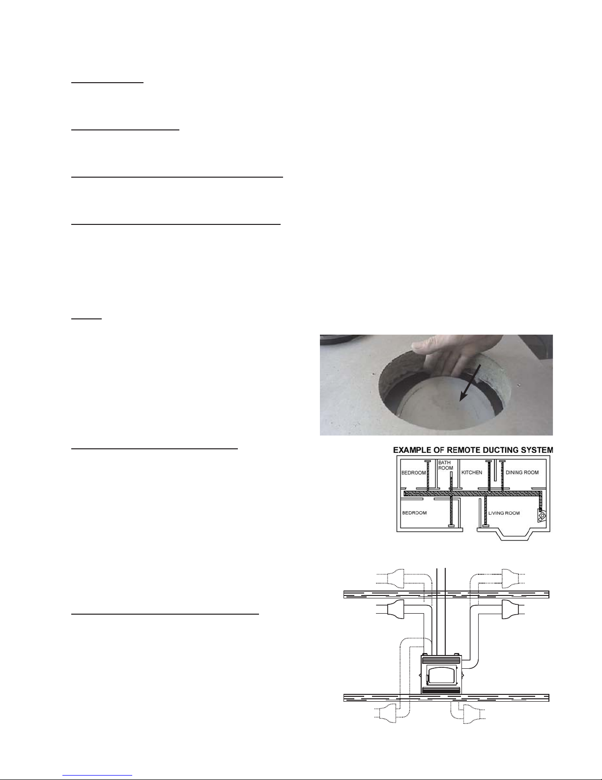
Model CZ-26 has the option of taking outside air directly
into the appliance through the opening on the left hand
side or taking inside air through the lower front louvres
or a combination of both.
If the optional fresh air kit (available through your
authorized dealer) is installed, it must not draw air from
the attic or garage. It may only come from outside the
house. The maximum length of the 4" air duct is 20 feet;
thereafter enlarge the duct to a 6" diameter.
Decide on the most convenient location for the fresh air inlet duct and hood which may be installed above or
below fl oor level.
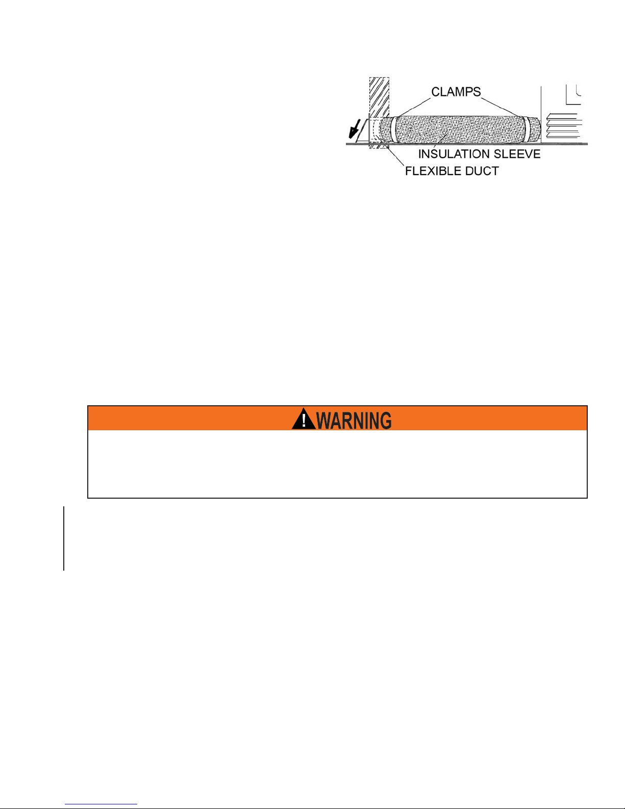
Make a 5" hole in an outside wall of the house. From outside, place the fresh air hood into the hole, open side
down.
At each end, carefully pull back the insulation sleeve exposing the fl exible duct. Place the insulated fl exible
duct over the fresh air hood and over the appliance outside air connector. Carefully push the insulation sleeve
back over the duct. Using the clamps, fasten the insulated duct into place on both sides.
11
For outside air only, re-install the inside air cover plate to cover the control box inside air opening. See "COMBUSTION AIR CONTROL" section.
A chimney venting the appliance shall not vent any other appliance.
3.3 HEARTH EXTENSION
HEARTH EXTENSIONS ARE TO BE INSTALLED ONLY AS DESCRIBED TO PREVENT HIGH
TEMPERATURES FROM OCCURRING ON CONCEALED COMBUSTIBLE MATERIALS. HEARTH
EMBER STRIPS PREVENT BURNING OR HOT PARTICLES FROM INADVERTENTLY FALLING
DIRECTLY ON COMBUSTIBLE SURFACES IN THE EVENT THE BUILDING SHOULD SETTLE AND
In the USA, a non-combustible (ie.brick, stone or ceramic tile) hearth extension must be installed projecting 16"
from the front and 6.75" from the sides of the appliance.
In Canada, a non-combustible (ie.brick, stone or ceramic tile) hearth extension must be installed projecting 18"
from the front and 8" from the sides of the appliance.
Ensure that the gap between the appliance and a factory-built hearth extension is sealed with sand/cement
grout or covered with a metal strip (or both) to prevent sparks and embers from falling into this area. A raised
hearth together with the appliance built on a raised platform is recommended for easier wood loading and fi re
viewing.
DISTURB THE ORIGINAL CONSTRUCTION.
W415-0893 / B / 08.01.12
12
4.0 INSTALLATION
NEVER INSTALL A SINGLE WALL SLIP SECTION OR SMOKE PIPE IN A CHASE STRUCTURE. THE HIGHER
TEMPERATURE OF THIS SINGLE WALL PIPE MAY RADIATE SUFFICIENT HEAT TO COMBUSTIBLE CHASE
DO NOT CONNECT THIS APPLIANCE TO A CHIMNEY SYSTEM SERVING ANOTHER APPLIANCE.
TO AVOID DANGER OF FIRE, ALL INSTRUCTIONS MUST BE STRICTLY FOLLOWED, INCLUDING THE
PROVISION OF AIR SPACE CLEARANCE BETWEEN CHIMNEY SYSTEM AND ENCLOSURE. TO PROTECT
AGAINST THE EFFECTS OF CORROSION ON THOSE PARTS EXPOSED TO THE WEATHER, WE
RECOMMEND THAT THE CHASE TOP BE PAINTED WITH A RUST-RESISTANT PAINT.
DO NOT FILL ANY FRAMED SPACE AROUND THE CHIMNEY WITH INSULATION OR ANY OTHER MATERIAL.
INSULATION PLACED IN THIS AREA COULD CAUSE ADJACENT COMBUSTIBLES TO OVERHEAT.
MAINTAIN A MINIMUM 2" AIR CLEARANCE TO ALL PARTS OF THE CHIMNEY SYSTEM AT ALL TIMES.
FAILURE TO MAINTAIN THIS 2" AIR CLEARANCE WILL CAUSE A STRUCTURE FIRE. NEVER FILL THIS
DETAILED INSTRUCTIONS FOR INSTALLATION OF THE CHASE TOP, STORM COLLAR AND TERMINATION
DO NOT CUT RAFTERS OR CEILING JOISTS WITHOUT FIRST CONSULTING A BUILDING OFFICIAL TO
ENSURE STRUCTURAL INTEGRITY IS NOT COMPROMISED.
FIRESTOP SPACERS MUST BE USED WHENEVER THE CHIMNEY PENETRATES A CEILING/FLOOR AREA.
THE TOTAL HORIZONTAL VENT LENGTH SHOULD NOT EXCEED 40% OF THE CHIMNEY HEIGHT ABOVE
THE STOVE. ALL HORIZONTAL SMOKE PIPE MUST SLOPE SLIGHTLY UPWARDS A MINIMUM OF 1/4” PER
FOOT AND ALL CONNECTIONS MUST BE TIGHT AND SECURED BY THREE SHEET METAL SCREWS
EQUALLY SPACED. AN UNINSULATED SMOKE PIPE SHALL NOT PASS THROUGH AN ATTIC, ROOF
SPACE, CLOSET OR SIMILAR CONCEALED SPACE, OR THROUGH A FLOOR, CEILING, WALL OR
PARTITION, OR ANY COMBUSTIBLE CONSTRUCTIONS.
DO NOT USE ANY MAKESHIFT MATERIALS DURING INSTALLATION.
!
WARNING
MATERIALS TO CAUSE A FIRE.
SPACE WITH ANY TYPE OF MATERIAL.
CAP ARE PACKAGED WITH THESE PARTS.
W415-0893 / B / 08.01.12
A
A
4.1 CHIMNEY
ALL VENTING CONNECTIONS MUST BE IN COMPLIANCE WITH THE CHIMNEY MANUF ACTURERS
This appliance was tested to CAN/ULC S610 and UL 127 Factory Built Fireplace Standards. This appliance has
met the test criteria for Zero Clearance Installation to Combustible Surfaces and Certifi ed to burn fi rewood only .
ny 6” diameter chimney listed to these standards may be installed. In accordance with these standards, the
appliance may also be connected to any chimney listed to CAN/ULC-S604 and CAN/ULC-S629 for Canada or
UL-103HT for the United states.
!
WARNING
INST ALLATION INSTRUCTIONS.
13
Installation of all types of factory-built chimney systems is to be in accordance with the chimney manufacturers installation instructions. An appropriate chimney manufacturers anchor base plate and anchor base plate gasket
is required in order to initiate their system. Use the high temperature gasket,
supplied, to seal between the anchor plate and the appliance top. Air cooled
chimney systems are not recommended in colder climates.
Complete installation instructions for Selkirk Ultra Temp Chimney for Canada
and Ultra Temp Platinum Chimney for USA, refer to: www.selkirkinc.com/products/chimney.aspx
chimney venting the appliance shall not vent any other appliance. The minimum overall chimney height from
the top of the appliance is 1 1 feet. The maximum overall chimney height from the top of the appliance is 34 feet.
Factory-built chimney systems for use in dwellings constructed for three or more families must be enclosed
above the room in which the appliance is located. This enclosure must have a fi re resistance rating equal to or
greater than that of the fl oor or roof assembly through which they pass.
The chimney should not be built with an offset angle in excess of 45° in Canada and 30° in USA.
Ensure that minimum clearances are maintained.
Portions of the chimney that extend through accessible spaces must always be encased to avoid personal
contact with the chimney and thereby avoid damage to the chimney.
The chimney must be supported at a maximum of 20 foot intervals (approx. 200 lbs/20 FT).
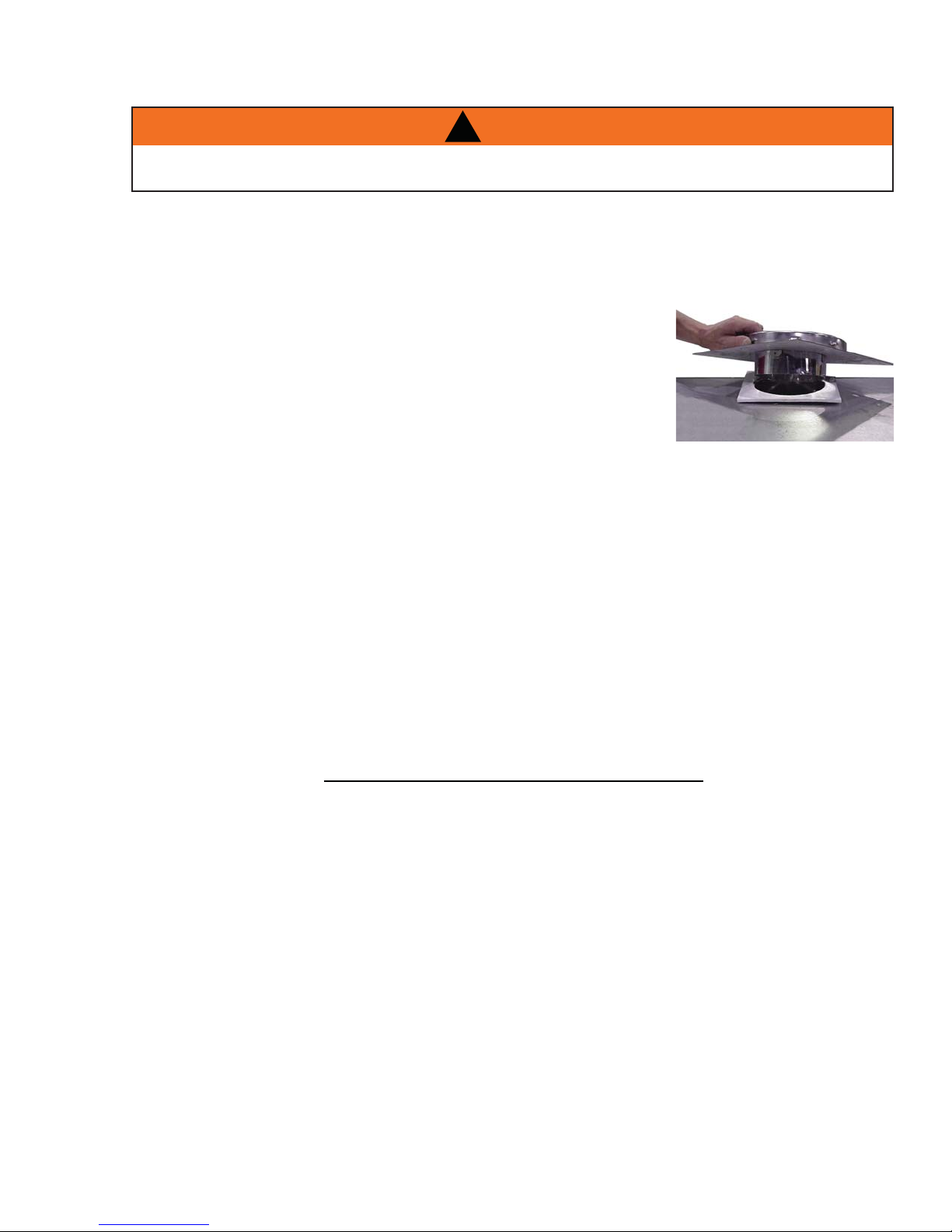
ANCHOR PLATE
ANCHOR PLATE GASKET
APPLIANCE TOP
ANCHOR PLATE FOR A
FACTORY BUILT CHIMNEY
63.4
W415-0893 / B / 08.01.12

14
4.2 TYPICAL CHIMNEY INSTALLATION
STORM COLLAR
ROOF FLASHING
ATTIC INSULATION
SHIELD
STRAIGHT CHIMNEY
RAIN CAP
MINIMUM
MAXIMUM
11 FT
34 FT
STORM COLLAR
ROOF FLASHING
ATTIC INSULATION
SHIELD
OFFSET
SUPPORT
SINGLE OFFSET
CHIMNEY
RAIN CAP
STORM COLLAR
ROOF FLASHING
ATTIC INSULATION
SHIELD
11 FT
MINIMUM
CEILING RADIATION
34 FT
MAXIMUM
FIRESTOP
12” MIN*
DOUBLE OFFSET
RAIN CAP
SHIELD
OFFSET
SUPPORT
CHIMNEY
11 FT
MINIMUM
34 FT
MAXIMUM
FIRESTOP
12” MIN*
* The fi rst fl ue offset closest to the top of the appliance must be a minimum distance of 12” from the
top of the appliance.
1. Move the appliance into position. Try to center the exhaust fl ue of the appliance,
midpoint between two joists to prevent having to cut them. Use a plumb bob to
line up the centre.
2. Cut and frame an opening in the ceiling to provide a
minimum clearance of 2” between the outside of the
chimney and any combustible material. DO NOT FILL
HEADERS
THIS SPACE WITH ANY TYPE OF MATERIAL! Nail
headers between the joists for extra support. Firestop
spacers must be placed on each framed opening in
any fl oor or ceiling that the chimney passes through.
FIRESTOP SPACER UNDERSIDE OF JOIST
3. Hold a plumb bob from the underside of the roof
to determine where the opening in the roof should
be. Cut and frame the roof opening maintaining
proper 2” clearances.
NOTE: 30° or 45° offsets may be installed back to
back.
2"
Min
2"
Min
Typical Joist Framing
63.1_2B
2"
Min
2"
Min
Typical Roof Joist
Framing
W415-0893 / B / 08.01.12
 Loading...