

Continental Fireplaces CDVS600-N, CDVS600-P, CDCS600-P, CDVC600-N, CS600-N Installation And Operation Instructions Manual
...
CERTIFIED UNDER CANADIAN AND AMERICAN NATIONAL STANDARDS, CSA 2.33, ANSI Z21.88 FOR VENTED GAS FIREPLACE HEATERS
INSTALLATION AND OPERATION INSTRUCTIONS FOR:
VENTED GAS FIREPLACE HEATER
1
NATURAL GAS MODELS CDVS600-N and CS600-N
PROPANE GAS MODELS CDVS600-P and CS600-P
Model CS600 is made up of Model CDVS600 and the Adapter Kit GS-150KT
WARNING:
If the information in these instructions is not followed exactly, a fire or
explosion may result causing property damage, personal injury or death.
FOR YOUR SAFETY
Do not store or use gasoline or other flammable vapours and liquids in the vicin-
ity of this or any other appliance.
WHAT TO DO IF YOU SMELL GAS:
• Do not try to light any appliance.
• Do not touch any electrical switch.
• Do not use any phone in your build
ing.
• Immediately call your gas supplier
from a neighbour's phone. Follow the
gas supplier's instructions.
• If you cannot reach your gas supplier,
call the fire department.
Installation and service must be performed by a qualified installer, service
agency or the gas supplier.
W415-0162 / E / 03.05.04
2
TABLE of CONTENTS
Pg
2-4 INTRODUCTION
Warranty
General Instructions
General Information
Care of Glass & Plated Parts
Shipping Bracket
5 LOCATION & CLEARANCES
6-12 DIRECT VENT SPECIFICS
MODEL CDVS600
Vent Lengths/Air Terminal Locations
Special Installation Example
Offset Installation Example
Horizontal Terminations
Orifice Replacement
Top Vent to Rear Vent Modification
Venting Parameters
Wall & Ceiling Protection
Horizontal Venting Installation
Vertical Venting Installation
Stove Vent Connection
Mobile Home Installation
13-14 B-VENT SPECIFICS
MODEL CS600
Chimney Installation
'B' Vent Installation
Combustion Air
Adding Vent Sections
Flashing and Storm Collar Installation
Pg
14 GAS INSTALLATION
15-16 FINISHING
Logo Placement
Front Cast Installation
Glass Door Closing & Opening
Log Placement
17-18 OPERA TION / MAINTENANCE
Spill Switch
Venting Action Check
Operating Instructions
Maintenance
19 BLOWER INSTALLATION
19 ADJUSTMENTS
Pilot Burner Adjustment
Venturi Adjustments
Restricting Vertical Vents
20-21 REPLACEMENTS
Ordering Replacement Parts
Termination Kits
Replacement Parts
Accessories
22-23 TROUBLE SHOOTING GUIDE
24 SERVICE HISTORY
PLEASE RETAIN THIS MANUAL FOR FUTURE REFERENCE
WARNING
• The stove is a vented gas-fired heater. Do not burn wood or other materials in this stove.
• Adults and especially children should be alerted to the hazards of high surface temperatures and should stay
away to avoid burns or clothing ignition. Supervise young children when they are in the same room as the
stove.
• Due to high temperatures, the stove should be located out of traffic and away from furniture and draperies.
• Clothing or other flammable material should not be placed on or near the stove.
• Any safety screen or guard removed for servicing must be replaced prior to operating the stove.
• It is imperative that the control compartments, burners and circulating blower and its passageway in the
stove and venting system are kept clean. The stove and its venting system should be inspected before use
and at least annually by a qualified service person. More frequent cleaning may be required due to excessive
lint from carpeting, bedding material, etc. The stove area must be kept clear and free from combustible
materials, gasoline and other flammable vapours and liquids.
• Under no circumstances should this stove be modified.
• This stove must not be connected to a chimney flue pipe serving a separate solid fuel burning appliance.
• Do not use this stove if any part has been under water. Immediately call a qualified service technician to
inspect the stove and to replace any part of the control system and any gas control which has been under
water.
• Do not operate the stove with the glass door opened, cracked or broken. Replacement of the glass should be
done by a licensed or qualified service person.
• Do not strike or slam shut the stove glass door.
• This fireplace uses and requires a fast acting thermocouple. Replace only with a fast acting thermocouple
supplied by Wolf Steel Ltd.
NOTE: changes, other than editorial, are denoted by a vertical line in the margin.
W415-0162 / E / 03.05.04

3
CONTINENTAL gas fireplaces are manufactured under the strict Standard of the world recognized
ISO 9001 : 2000 Quality Assurance Certificate.
CONTINENTAL products are designed with superior components and materials, assembled by trained craftsmen
who take great pride in their work. The burner and valve assembly are leak and test-fired at a quality test station.
Once assembled the complete fireplace is thoroughly inspected by a qualified technician before packaging to ensure
that you, the customer, receives the quality product that you expect from WOLF STEEL Ltd..
CONTINENTAL GAS FIREPLACE PRESIDENT'S LIFETIME LIMITED WARRANTY
The following materia ls an d wor kmans hip i n you r new CONTINENTAL gas fireplace are
warranted against de
heat exchanger, stainless
only), gold plated parts again
extrusion trims.
fects for as long as you own the fireplace. This covers: combustion chamber,
steel burner, phazer™ logs and embers, ceramic glass (thermal breakage
st tarnishing, porcelainized enamelled components and aluminium
Electrical (110V and m
thermal switch, switc hes, wiring,
cov ere d and WOLF STEEL LTD. will provide r
illivolt) components and wearable parts such as blowers, gas valves,
remote controls, igniter, gasketing, and pilot assembly are
eplac ement par ts free of cha rge durin g the first
year of t he limited warranty.
Any labour related to wa
rrant y repai r is not covered.
CONDITIONS AND LIMITATIONS
WOLF STEEL LTD. warrants its products against manufacturing defects to the original purchaser only -- i.e., the individual or legal entity (registered customer) whose name appears on
the warranty registration card filed with WOLF STEELLtd. -- provided that the purchase was made through an authorized CONTINENTALdealer and is subject to the following conditions and
limitations:
This factory warranty is nontransferable and may not be extended whatsoever by any of our representatives.
The gas fireplace must be installed by a licenced, authorized service technician or contractor. Installation must be done in accordance with the installation instructions included with the
product and all local and national building and fire codes.
This limited warranty does not cover damages caused by misuse, lack of maintenance, accident, alterations, abuse or neglect and parts installed from other manufacturers will nullify this
warranty.
This limited warranty further does not cover any scratches, dents, corrosion or discolouring caused by excessive heat, abrasive and chemical cleaners nor chipping on porcelain enamel
parts, mechanical breakage of PHAZER™ logs and embers, nor any venting components used in the installation of the fireplace.
WOLF STEEL Ltd. warrants its stainless steel burners against defects in workmanship and material for life, subject to the following conditions: During the first 10 years WOLF STEEL Ltd.
will replace or repair the defective parts at our option free of charge. From 10 years to life, WOLF STEEL LTD. will provide replacement burners at 50% of the current retail price.
In the first year only, this warranty extends to the repair or replacement of warranted parts which are defective in material or workmanship provided that the product has been operated in
accordance with the operation instructions and under normal conditions.
After the first year, with respect to this President's Limited Lifetime Warranty, WOLF STEEL LTD. may, at its discretion, fully discharge all obligations with respect to this warranty by refunding
to the original warranted purchaser the wholesale price of any warranted but defective part(s).
WOLF STEEL Ltd. will not be responsible for installation, labour, or any other costs or expenses related to the reinstallation of a warranted part, and such expenses are not covered by this
warranty.
Notwithstanding any provisions contained in this President's Limited Lifetime Warranty, WOLF STEEL’S responsibility under this warranty is defined as above and it shall not in any event
extend to any incidental, consequential or indirect damages.
This warranty defines the obligations and liability of WOLF STEEL Ltd. with respect to the CONTINENTAL gas fireplace and any other warranties expressed or implied with respect to this
product, its components or accessories are excluded.
WOLF STEEL Ltd. neither assumes, nor authorizes any third party to assume, on its behalf, any other liabilities with respect to the sale of this product. WOLF STEEL Ltd. will not be responsible
for: over-firing, downdrafts, spillage caused by environmental conditions such as rooftops, buildings, nearby trees, hills, mountains, inadequate vents or ventilation, excessive venting
configurations, insufficient makeup air, or negative air pressures which may or may not be caused by mechanical systems such as exhaust fans, furnaces, clothes dryers, etc.
Any damages to fireplace, combustion chamber, heat exchanger, brass trim or other component due to water, weather damage, long periods of dampness, condensation, damaging chemicals
or cleaners will not be the responsibility of WOLF STEEL Ltd.
The bill of sale or copy will be required together with a serial number and a model number when making any warranty claims from your authorized dealer. The warranty registration card
must be returned within fourteen days to register the warranty.
WOLF STEEL Ltd. reserves the right to have its representative inspect any product or part thereof prior to honouring any warranty claim.
ALL SPECIFICATIONS AND DESIGNS ARE SUBJECT TO CHANGE WITHOUT PRIOR NOTICE DUE TO ON-GOING PRODUCT IMPROVEMENTS. NAPOLEON® IS A REGISTERED
TRADEMARK OF WOLF STEEL LTD. PATENTS U.S. 5.303.693.801 - CAN. 2.073.411, 2.082.915. © WOLF STEEL LTD.
W415-0162 / E / 03.05.04
4
GENERAL INSTRUCTIONS
THIS GAS ST OVE SHOULD BE INSTALLED AND SERVICED
BY A QUALIFIED INSTALLER to conform with local codes.
Installation practices vary from region to region and it is important
to know the specifics that apply to your area,
for example: in Massachusetts State:
• The fireplace damper must be removed or welded in the open
position prior to installation of a fireplace insert or gas log.
• The appliance off valve must be a “T” handle gas cock.
• The flexible connector must not be longer than 36 inches.
• The appliance is not approved for installation in a bedroom or
bathroom unless the unit is a direct vent sealed combustion
product.
• WARNING: This product must be installed by a licensed plumber
or gas fitter when installed within the commonwealth of
Massachusetts.
In absence of local codes, install to the current CAN1-B149
Installation Code in Canada or to the National Fuel Gas Code,
ANSI Z223.1, and NFPA 54 in the United States. Mobile home
installation must conform with local codes. In the absence of
local codes, install to the current standard for gas equipped
mobile housing CAN/CSA Z240 MH Series in Canada or the
manufactured home construction and safety standard, Title 24
CFR, part 3280, or the Fire Safety Criteria for manufactured
home installations, Sites and Community Standard ANSI/NFPA
501A in the United States.
Purge all gas lines with the glass door of the stove removed.
Assure that a continuous gas flow is at the burner before reinstalling the door.
Under extreme vent configurations, allow several minutes (5-
15) for the flame to stabilize after ignition.
It is recommended that all horizontal runs have a ¼ inch rise
per foot.
Objects placed in front of the stove must be kept a minimum
of 48" away from the front face of the unit.
The stove and its individual shutoff valve must be disconnected
from the gas supply piping system during any pressure testing of
that system at test pressures in excess of 1/2 psig (3.5 kPa). The
stove must be isolated from the gas supply piping system by
closing its individual manual shutoff valve during any pressure
testing of the gas supply piping system at test pressures equal to
or less than ½ psig (3.5 kPa).
The stove, when installed with a blower, must be electrically
connected and grounded in accordance with local codes. In the
absence of local codes, use the current CSA C22.1 CANADIAN
ELECTRICAL CODE in Canada or the ANSI/NFPA 70-1996
NA TIONAL ELECTRICAL CODE in the United States. The blower
power cord must be connected into a properly grounded receptacle.
The grounding prong must not be removed from the cord plug.
GENERAL INFORMATION
FOR YOUR SATISFACTION, THIS STOVE HAS BEEN TESTFIRED TO ASSURE ITS OPERA TIONAND QUALITY!
Minimum inlet gas supply pressure is 4.5 inches water column for
natural gas and 11 inches water column for propane. Maximum
inlet gas pressure is 7 inches water column for natural gas and 13
inches water column for propane. When the valve is set to "HI", the
manifold pressure under flow conditions is 3.5 inches water column
for natural gas and 10 inches water column for propane. When the
fireplace is installed at elevations above 4,500ft, and in the absence
of specific recommendations from the local authority having jurisdiction, the certified high altitude input rating shall be reduced at the
rate of 4% for each additional 1,000ft.
W415-0162 / E / 03.05.04
Change in flame appearance from "HI" to "LO" is more evident in natural gas than in propane. Expansion / contraction
noises during heating up and cooling down cycles are normal and to be expected.
This appliance is only for use with the type of gas indicated
on the rating plate. (See page 14). This appliance is not
convertible for use with other gases, unless a certified kit
is used.
INSTALLER: It is your responsiblity to check off the
appropriate box on the rating plate according to the
model,
venting and gas type of the unit.
CARE OF GLASS, AND PLATED PARTS
Do not use abrasive cleaners to clean these parts. Buff
lightly with a clean dry cloth.
The glass is
Continental / Wolf Steel Ltd. dealer. DO NOT SUBSTITUTE
MATERIALS. Clean the glass after the first 10 hours of operation with a recommended gas fireplace glass cleaner.
Thereafter clean as required. DO NOT CLEAN GLASS
WHEN HOT! If the glass is not kept clean permanent discolouration and / or blemishes may result.
3
/16" ceramic glass available from your
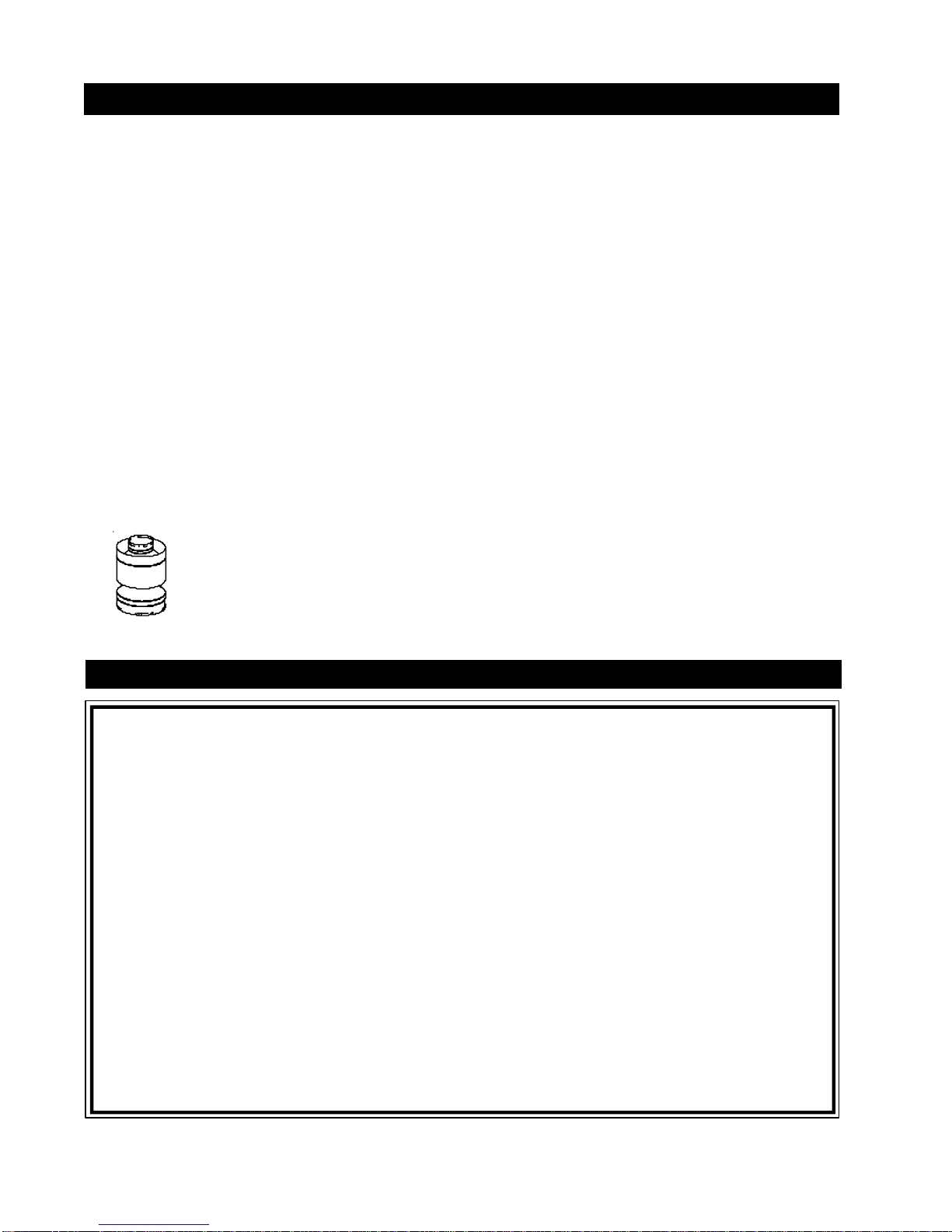
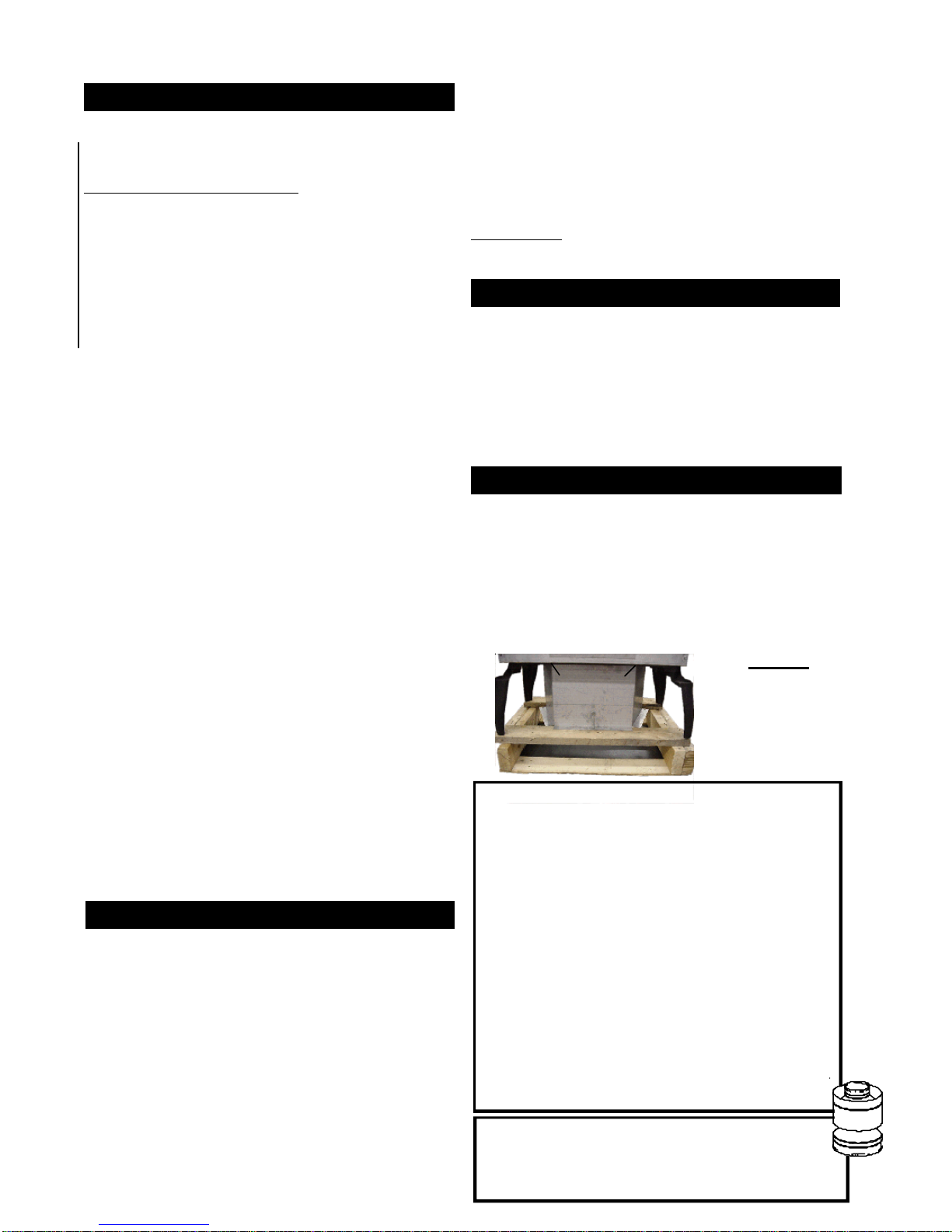
SHIPPING BRACKET
To avoid the stove being damaged during shipping, a shipping bracket has been used and must be unbolted before
the stove can be installed.
1. Remove the four nuts holding the shipping bracket to the
bottom of the stove.
2. Lift the stove up and away from the skid to clear the
threaded bolts sticking through the bracket. Set down on a
flat surface. The stove top is not secured to the unit.
3. Discard the nuts, bracket and the skid.
FIGURE 1
4 NUTS
SHIPPING
BRACKET
CDVS600: TOP VENT / REAR VENT
VERTICAL TERMINATION:
put is 35,000 BTU/hr for natural gas and 31,500 BTU/hr
for propane. Maximum output for natural gas is 27,300
BTU/hr at an efficiency of 78%. Maximum output for propane is 24,570 BTU/hr at an efficiency of 78%. Maximum A.F.U.E. (annual fuel utilization efficiency) rating is
72% for natural gas and 71% for propane.
Maximum in-
REAR VENT HORIZONTAL TERMINATION:
and propane gas. This application requires changing
the main burner orifice.
This stove is not approved for closet or recessed installations. It is approved for bathroom, bedroom and bedsitting room installations.
This stove may be installed in an aftermarket permanently located, manufactured (mobile) home, where not
prohibited by local codes.
Maximum input is 21,000 BTU/hr for natural
CS600: Maximum input is 35,000 BTU/hr for natu-
ral gas and 31,500 BTU/hr for propane. This stove is
approved for bedroom and bed-sitting room installations.
LOCATION & CLEARANCES
5
Provide adequate ventilation and combustion air.
Provide adequate accessibility clearance for servicing
and operating the stove.
Never obstruct the front opening of the stove.
CDVS600 AND CS600
As long as clearance to combustibles is kept within the
required distances, the most desirable and beneficial location for a Continental stove is in the centre of a building,
thereby allowing the most efficient use of the heat created.
The location of windows, doors and the traffic flow in the
room where the stove is to be located should be considered. If possible, you should choose a location where the
vent will pass through the house without cutting a floor or
roof joist.
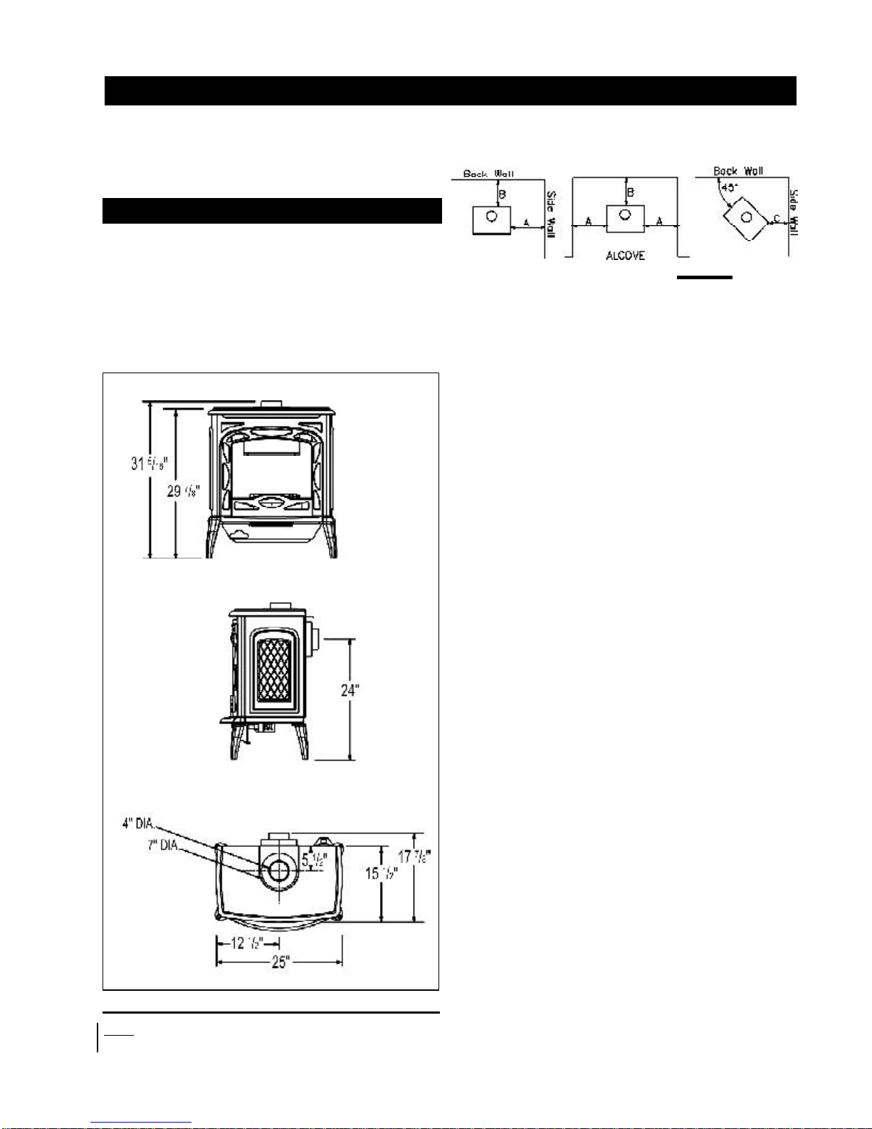
MAINTAIN THESE MINIMUM CLEARANCES TO
COMBUSTIBLES:
FIGURE 3
A. 6" B. 6" C. 2"*
NO ADDITIONAL FLOOR PROTECTION IS REQUIRED
MINIMUM 20" FROM STOVE TOP TO CEILING
6" TO SINGLE WALL CONNECTOR
1" TO DIRECT VENT AND B-VENT
*ATA DISTANCE OF 2" FROM THE WALL, ACCESS TO THE BLOWER
SWITCH
, ON-OFF SWITCH OR THE BLOWER POWER CORD MAY NOT
BE PRACTICAL
.
A te r minal shall not terminate di rectly above a
side walk or pa ved dr i vew a y whic h is lo cat e d
between two
single family dwellings and serves
both dwellings. Local codes or regulations may
require different cl
earances.
Do not allow the inside liner to bunch up on horizontal
or vertical runs and elbows. Keep it
pulled tight. A 1-1/
4" air gap all around between the inner liner and outer
stove pipe is required for
safe operation. Use a firestop
when penetrating interior walls, floor or ceiling.
FIGURE 2 - SHOWN WITH OPTIONAL FRONT INSTALLED
NOTE: The total width of the stove is increased to 39" width with the
optional side shelves attached.
W415-0162 / E / 03.05.04
6
DIRECT VENT SPECIFICS - MODEL CDVS600
VENTING LENGTHS &
AIR TERMINAL LOCATIONS
Use only Wolf Steel or Simpson Dura-Vent Model DV-GS
venting components. Minimum and maximum vent lengths,
for both horizontal and vertical installations, and air terminal locations for either system are set out in this manual
and must be adhered to. For Simpson Dura-Vent, follow
the installation procedure provided with the venting components. Both Wolf Steel and Simpson Dura-Vent venting
components may have a 0" rise per foot on horizontal runs.
When using Wolf Steel venting components, use only the
following vent kits: WALL TERMINAL KIT GD175 (7-1/2' of
venting included), or 1/12 TO 7/12 PITCH ROOF TERMINAL
KIT GD110, 8/12 TO 12/12 ROOF TERMINAL KIT GD111,
FLAT ROOF TERMINAL KIT GD11 2 or STOVE PERISCOPE
KIT GD180 (for wall penetration below grade) in conjunc-
tion with the appropriate venting components.
For optimum performance, it is recommended that all horizontal runs have a minimum ¼ inch rise per
foot.
These vent kits allow for either
horizontal or vertical venting of
the stove. The maximum
number of 4" flexible
connections is two horizontally
or three vertically (excluding
FIGURE 4
the stove and the air terminal
connections).
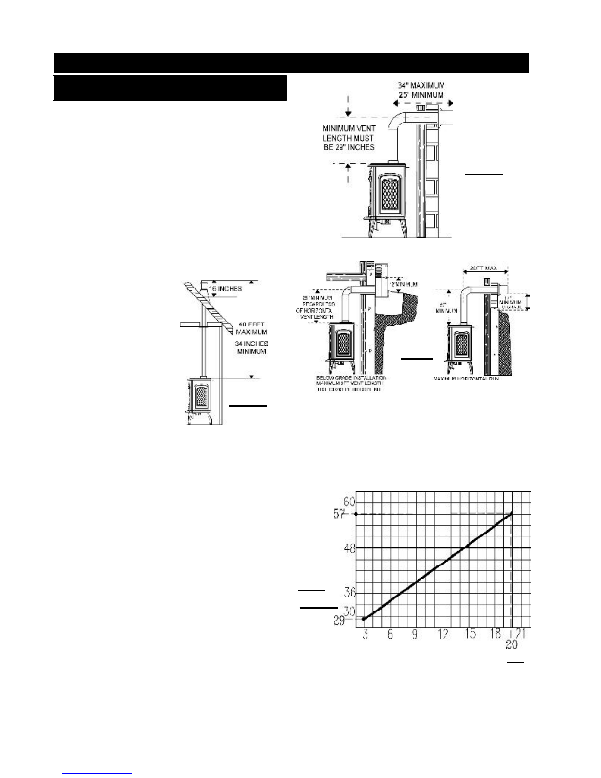
When terminating vertically, the minimum vertical rise is
34 inches above the stove and the maximum vertical rise
is 40 feet. FIGURE 4.
Deviation from the minimum vertical vent length can create difficulty in burner start-up and/or carboning.
Use an adjustable pipe as the final length of rigid piping
to the stove for ease of installation.
For optimum flame appearance and stove performance,
keep the vent length and number of elbows to a minimum.
The air terminal must remain unobstructed at all times.
Examine the air terminal at least once a year to verify that it
is unobstructed and undamaged.
o
The maximum horizontal run is 34 inches with a 90
elbow
located 29" above the stove. FIGURE 5.
The maximum horizontal run with a 57 inch vertical rise
immediately above the stove is 20 feet . FIGURES 6a & b.
IF VERTICAL RISES GREATER THAN 57 INCHES ARE NECESSARY, THE INCREASED RISE MUST BE DEDUCTED FROM THE
MAXIMUM HORIZONTA L RUN.
HORIZONTAL RUN NOT TO
EXCEED VERTICAL RISE
Use the chart on this page to calculate horizontal runs for
vertical rises between 29 and 57 inches. W hen calculating
maximum run lengths, include 5 feet for each 90° or 45°
elbow.
(DO NOT INCLUDE THE FIRST ELBOW DIRECTLY OFF
THE UNIT . )
REQUIRED
VERTICAL
RISE FROM
FIREPLACE
TO FIRST ELBOW IN
INCHES
FIGURE 7
FIGS 6a-b
FIGURE 5
W415-0162 / E / 03.05.04
CALCULATED HORIZONTAL VENT RUN IN FEET
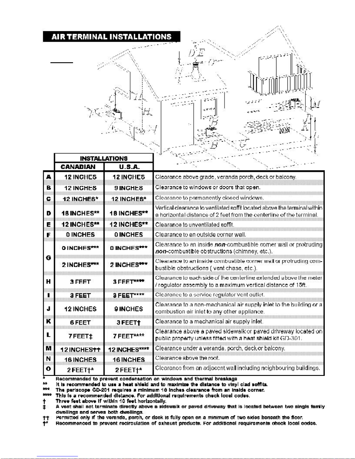
FIGURE 8
7
W415-0162 / E / 03.05.04
8
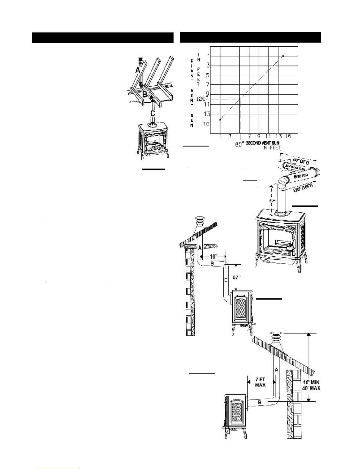
SPECIAL INSTALLATION EXAMPLE
When a horizontal offset is required in a through-the-roof
installation, the following procedure for vent length calculations must be followed:
In an installation as shown in FIGURES
9 & 12, lengths A and C are known
based on room height and roof requirements.
Length C must never be less than 29
inches. Any 90° and 45° elbows must
be calculated as 5 feet of venting
each.
The allowable horizontal run can be
calculated using these parameters. In
this example, the total vertical height is
20 feet (length "A" is required to be 11
feet while length "C" needs to be 9 feet).
The maximum vertical length is 40 feet
and all runs and elbows must be subtracted from this maximum vertical
length.
The maximum allowable horizontal run that "B" can be is:
40 ft. (maximum vertical run length)
-11 ft. (through the roof vertical rise "A")
-10 ft. (2 - 90° elbow)
- 9 ft. (vertical run
10 ft. (maximum allowable horizontal length for "B")
The length of "B" must never be greater than the length
of "A" and "C" combined.
"C")
FIGURE 9
OFFSET INSTALLATION EXAMPLE
FIGURE 10
If a first run of 120 inches is re-
quired, using the "First Vent Run"
on the chart shows that a maxi-
mum second run of 60 inches
is allowable.
IF NECESSAR Y, THE FIRST
RUN AND THE SECOND
RUN MAY BE REVERSED.
FIGURE 11
The maximum allowable horizontal run that "A" in Figure 13
can be is:
40 ft. (maximum vertical run length)
- 7 ft. (horizontal run
33 ft. (maximum allowable vertical length for "A")
"B")
FIGURE 12
FIGURE 13
W415-0162 / E / 03.05.04
 Loading...