

Continental Fireplaces CL38, CL50 Owner's Manual

ENGLISH
FRENCH
PG. 25
OWNER’S MANUAL
CL38 / CL50
Linear Gas Appliance
For indoor use only
SAFETY INFORMATION
!
WARNING
FIRE OR EXPLOSION HAZARD
Failure to follow safety warnings exactly could result in serious injury, death, or property damage.
- Do not store or use gasoline or other flammable vapors and liquids in the vicinity of this or any other appliance.
- WHAT TO DO IF YOU SMELL GAS:
• Do not try to light any appliance.
• Do not touch any electrical switch; do not use any phone in your building.
• Immediately call your gas supplier from a neighbour’s phone. Follow the gas supplier’s instructions.
• If you cannot reach your gas supplier, call the fire department.
- Installation and service must be performed by a qualified installer, service agency, or the supplier.
Wolf Steel Ltd., 24 Napoleon Rd., Barrie, ON, L4M 0G8 Canada / 103 Miller Drive, Crittenden, Kentucky, USA, 41030
Phone 1 (866) 820-8686 • www.continentalfireplaces.com • hearth@continentalproducts.com
W415-1714 / A / 06.11.18

EN
safety information
WARNING
!
• This appliance is hot when operated and can cause
severe burns if contacted.
• Any changes to this appliance or its control can be
dangerous and are prohibited.
• Do not operate appliance before reading and
understanding operating instructions. Failure to operate appliance according to operating instructions
could cause fire or injury.
• Risk of fire or asphyxiation! Do not operate appliance with fixed glass removed.
• Do not connect 110 volts to the control valve.
• Risk of burns! The appliance should be turned off
and cooled before servicing.
• Do not install damaged, incomplete, or substitute
components.
• Risk of cuts and abrasions. Wear protective gloves
and safety glasses during installation. Sheet metal
edges may be sharp.
• Children and adults should be alerted to the hazards of high surface temperatures, and should stay
away to avoid burns or clothing ignition.
• Young children should be carefully supervised
when in the same room as the appliance. Toddlers,
young children, and others may be susceptible
to accidental contact burns. A physical barrier is
recommended if there are at-risk individuals in the
house. To restrict access to an appliance or stove,
install an adjustable safety gate to keep toddlers,
younger children, and other at-risk individuals out
of the room and away from hot surfaces.
• Clothing or other flammable material should not be
placed on or near the appliance.
• Due to high temperatures, the appliance should be
located out of traffic and away from furniture and
draperies.
• Ensure you have incorporated adequate safety
measures to protect infants / toddlers from touching hot surfaces.
• Even after the appliance has been turned off, the
glass and/or screen will remain hot for an extended
period of time.
• Check with your local hearth speciality dealer for
safety screens and hearth guards to protect children from hot surfaces. These screens and guards
must be fastened to the floor.
• Any safety screen, guard, or barrier removed for
servicing of the appliance must be replaced prior to
operating the appliance.
• The appliance is a vent gas-fired appliance. Do not
burn wood or other materials in the appliance.
• The appliance area must be kept clear and free
from combustible materials, gasoline, and other
flammable vapours and liquids.
• Under no circumstances should this appliance be
modified.
• This appliance must not be connected to a chimney
flue pipe serving a separate solid fuel-burning appliance.
• Do not use this appliance if any part has been under
water. Immediately call a qualified service technician
to inspect the appliance and to replace any part of
the control system and any gas control which has
been under water.
• Do not operate the appliance with the glass door
removed, cracked, or broken. Replacement of the
glass should be done by a licensed or qualified
service person.
• Do not strike or slam shut the appliance glass door.
• When equipped with pressure relief doors, they
must be kept closed while the appliance is operating to prevent exhaust fumes containing carbon
monoxide from entering the home. Temperatures of
the exhaust escaping through these openings can
also cause the surrounding combustible materials to
overheat and catch fire.
• Only doors / optional fronts certified with the appliance are to be installed on the appliance.
• Keep the packaging materials out of reach of
children and dispose of the material in a safe manner. As with all plastic bags, these are not toys and
should be kept away from children and infants.
• As with any combustion appliance, we recommend
having your appliance regularly inspected and serviced as well as having a carbon monoxide detector
installed in the same area to defend you and your
family against carbon monoxide.
• Ensure clearances to combustibles are maintained
when building a mantel or shelves above the appliance. Elevated temperatures on the wall or in the
air above the appliance can cause melting, discolouration, or damage to decorations, TVs, or other
electronic components.
• A barrier designed to reduce the risk of burns from
the hot viewing glass is provided with the appliance
and must be installed.
• If the barrier becomes damaged, the barrier must
be replaced with the manufacturer’s barrier for this
appliance.
• Installation and repair should be done by a qualified
service person. This appliance should be inspected
before use and at least annually by a professional
service person. More frequent cleaning may be required due to excessive lint from carpeting, bedding
material, etc. It is imperative that control compartments, burners, and circulating air passageways of
the appliance be kept clean.
2
W415-1714 / A / 06.11.18
SAFETY BARRIER
DANGER
HOT GLASS WILL CAUSE
BURNS.
DO NOT TOUCH GLASS UNTIL
COOLED.
NEVER ALLOW CHILDREN TO
TOUCH GLASS.
!
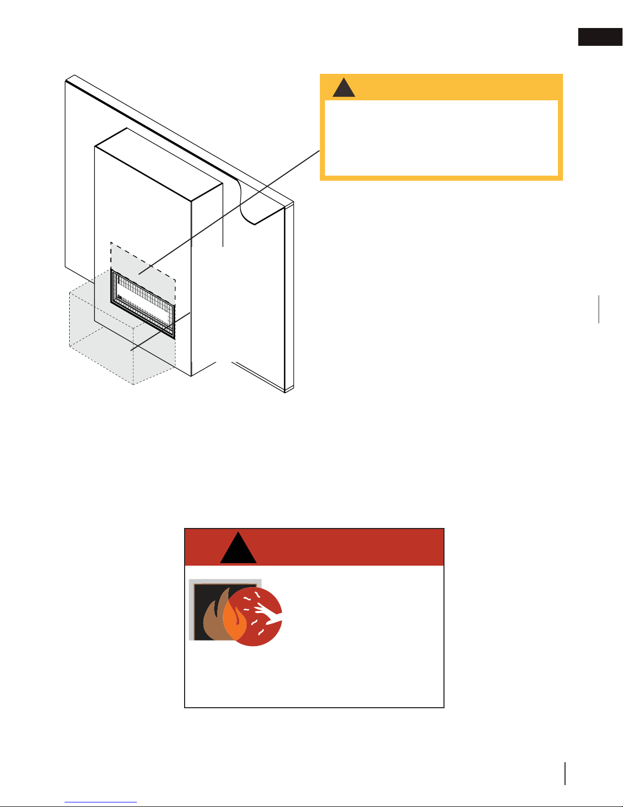
WARNING
Fireplaces
generate radiant
heat. Do not put
objects in front
of the appliance
(minimum
distance of 4
feet).
clear space
WARNING
!
The area above the appliance gets
hot. Combustible objects or materials
must never be placed in this area. For
minimum distance, refer to installation
manual or your authorized dealer.
EN
A barrier designed to reduce the risk of burns from
the hot viewing glass is provided with this appliance
and shall be installed for the protection of children
and other at-risk individuals.
!
HOT GLASS WILL CAUSE BURNS.
DO NOT TOUCH GLASS UNTIL
COOLED.
NEVER ALLOW CHILDREN TO
TOUCH GLASS.
W415-1714 / A / 06.11.18
3
EN
welcome
congratulations!
Continental is proudly committed to your total home comfort. We are proud to say that our products continunously
surpass industry standards and our inspiration is you! More than anything, we want you to feel confident in
choosing Continental for your home. Our products are designed to provide that confidence and ensure that every
Continental product is beyond compare.
Continental products are designed with superior components and materials assembled by trained craftsmen who
take great pride in their work.
A barrier designed to reduce the risk of burns from the hot viewing glass is provided with the appliance for your
safety. This barrier must be installed.
Your Continental appliance has been thoroughly inspected by a qualified technician before packaging to ensure
that you, the customer, receives the quality product that you expect from Continental.
Dealer : Fill in your dealer information (or business card) and the appliance installation information
below.
Dealer Information
Name of Dealer:
Dealer Location:
Dealer Phone:
Dealer E-mail:
Customer:
Customer Address:
Date of Installation:
Location of the appliance:
Installer:
Serial Number:
Model:
Natural Gas:
CL38N
CL50N
4
W415-1714 / A / 06.11.18
Dealer: Business card location
Propane:
CL38N2
CL50N2
CL38P
CL50P
CL38P2
CL50P2

table of contents
1.0 getting to know your appliance 6
1.1 control access 7
1.2 rating plate / lighting instructions location 8
2.0 operating your appliance 9
2.1 using your appliance 9
2.2 on/off components 9
2.2.1 changing the batteries in the battery holder 10
2.2.2 turndown 10
3.0 clearances around appliance 11
4.0 maintenance 12
4.1 care of glass 13
4.2 care of plated parts 14
4.3 safety barrier removal 14
4.4 door trim removal 15
4.5 firebox glass door removal 16
4.6 anti-condensation switch 16
5.0 replacement parts 17
6.0 accessories 18
7.0 troubleshooting 20
7.1 frequently asked questions 21
8.0 warranty 22
9.0 service history 23
EN
note:
The information throughout this manual is believed to be correct at the time of printing. Wolf Steel
Ltd. reserves the right to change or modify any information within this manual at any time without
notice. Changes, other than editorial are denoted by a vertical line in the margin.
W415-1714 / A / 06.11.18
5
EN
1.0 getting to know your appliance
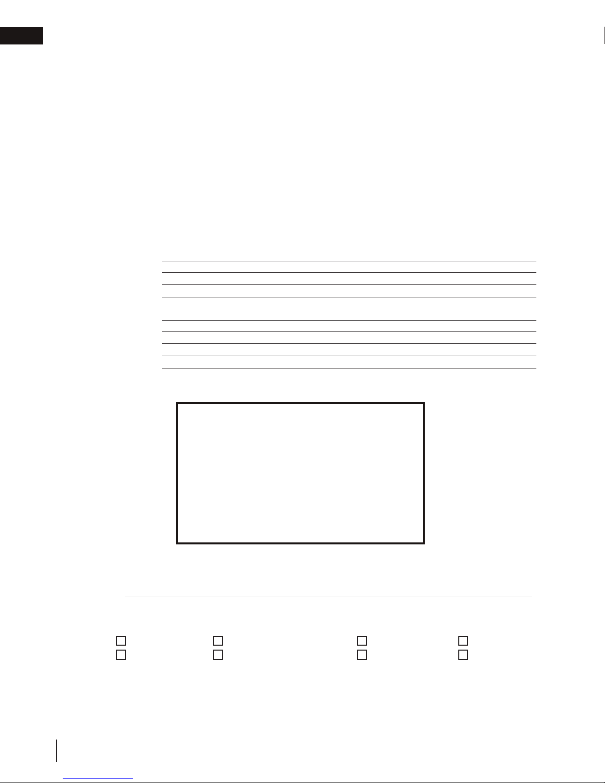
getting to know your appliance
This owner’s manual is written for a complete series of linear appliances that have a variety of different features
and specifications. Before reading this manual, be sure you know which model of appliance that you have. This
information will have been filled out by the installer on the proceeding page and on the rating plate that is permanently attached to the appliance (see “rating plate / lighting instructions” section).
This manual is for the:
• CL38 models
• CL50 models
If required, more detailed technical information is included in the appliance installation manual.
The information throughout this manual is believed to be correct at the time of printing. Wolf Steel Ltd. reserves
the right to change or modify any information within this manual at any time without notice. Changes, other than
editorial are denoted by a vertical line in the margin.
Visit the Continental website (continentalfireplaces.com) for the most current version of your appliance’s manual.
Valve / rating
plate / lighting
instructions /
battery holder
location
Safety barrier
Door trim
Firebox
glass door
Some features and components illustrated may vary depending on your model.
6
W415-1714 / A / 06.11.18
Control cover
Single-sided
model illustrated
BurnerPilot
getting to know your appliance
PRE-FINISHING
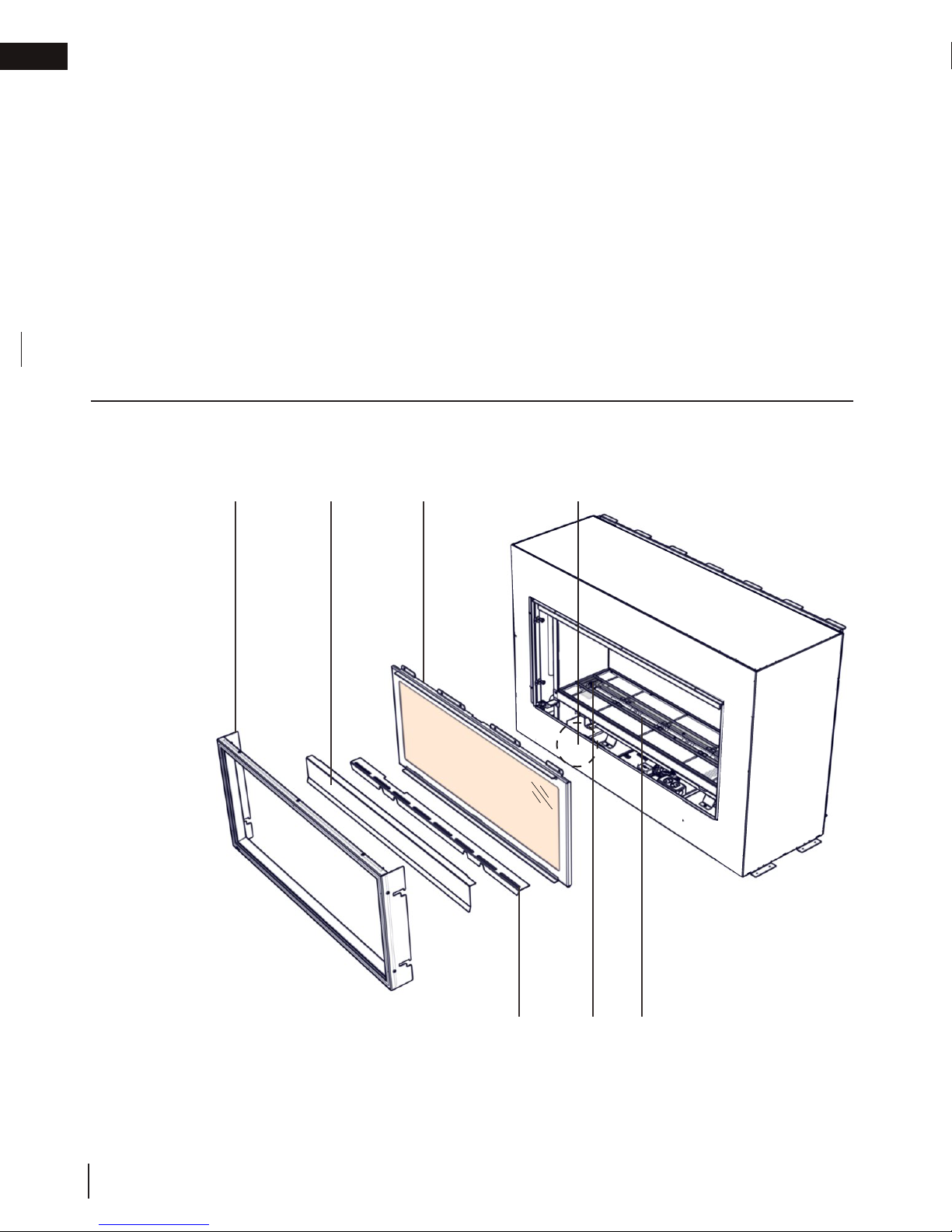
The term “access side” is used in this manual and refers to the open side of the appliance where the firebox glass
door is located.
In the case of see-thru appliances, there are firebox glass doors on both sides of the appliance. One of these
doors is fixed and cannot be removed. The access side can be identified with the pilot location.
EN
pilot location
access side
fixed side
pilot location
1.1 control access
Access to the control can be done by removing the safety barrier, glass door, door trim and control cover (see
“maintenance” section for instructions on how to remove these components).
VALVE
CONTROL
MODULE
FLAME ADJUSTMENT
ELECTRICAL
BOX
PRE-FINISHING
ACCESS PANEL
W415-1714 / A / 06.11.18
7
EN
NORME DE SECURITÉ ET DE CONSTRUCTION DE MAISONS MANUFACTURÉES, TITRE 24 CFR, SECTION 3280. DANS LE CAS OU CETTE NORME D'ÉTATS-UNIS NE PEUT ÊTRE APPLIQUÉE, SE RÉFÉRER A LA NORME
SAMPLE
getting to know your appliance
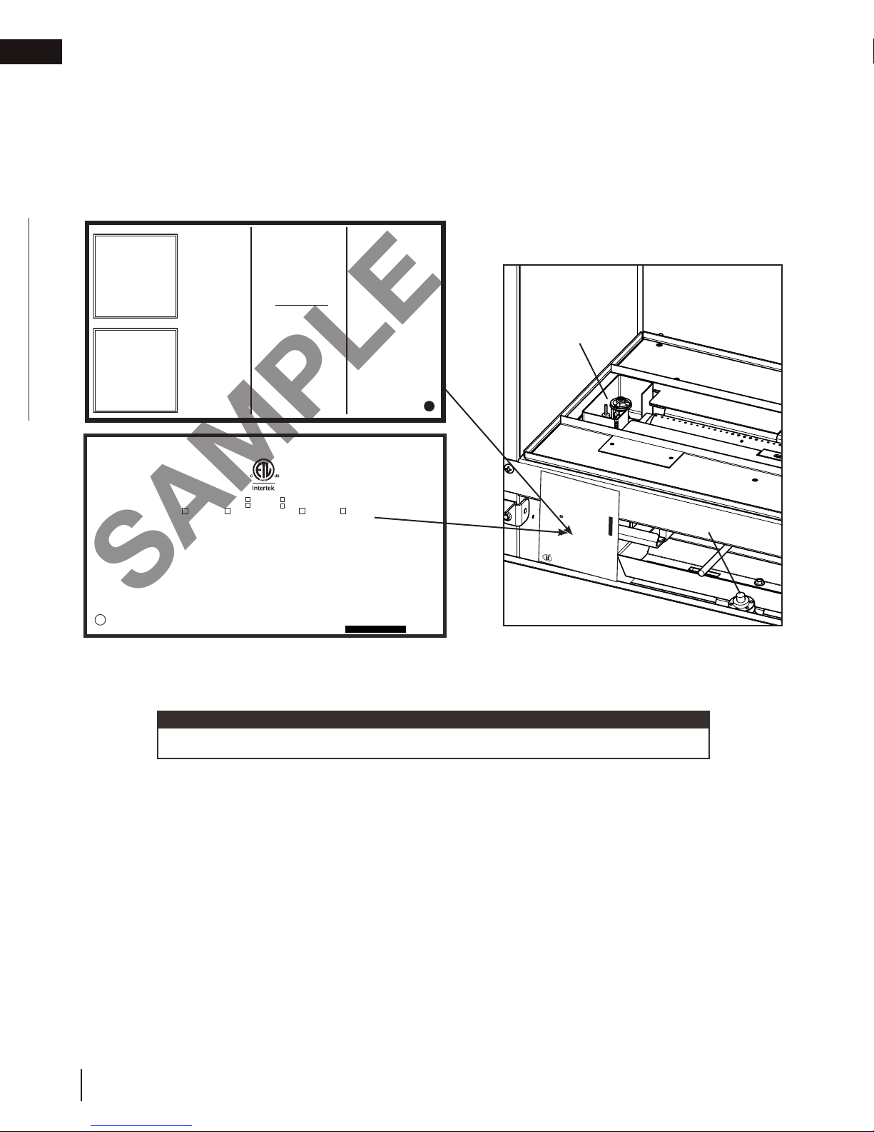
1.2 rating plate / lighting instructions location
Both the rating plate and lighting instructions are attached to a chain located on the left side of the control area
near the valve (access side). Remove the safety barrier or glass guard and the control cover to gain access to the
control area, see “control access” section.
To replace, slide the instructions back into the control area and slide the glass front into its locked position.
WARNING:
IMPROPER INSTALLATION,
KEEP BURNER AND CONTROL
COMPARTMENT CLEAN. SEE
INSTALLATION MANUAL.
APPLIANCE NEEDS FRESH
AIR FOR SAFE OPERATION
AND MUST BE INSTALLED
WITH ADEQUATE PROVISIONS
FOR COMBUSTION
AND VENTILATION AIR.
GARDEZ LE BRÛLEUR ET LE
COMPARTIMENT DES
CONTRÔLES PROPRES.
CONSULTEZ LE MANUEL
D’INSTALLATION. PAR
MESURE DE SÉCURITÉ.
CET APPAREIL DOIT
ÊTRE ALIMENTÉ EN AIR
FRAIS ET AVEC SUFFISANT
D’AIR COMBURANT ET
DE VENTILATION.
CERTIFIED TO CANADIAN AND AMERICAN NATIONAL STANDARDS: CSA 2.22-2016 AND ANSI Z21.50-2016 FOR VENTED DECORATIVE GAS FIREPLACES.
CERTIFIÉ SELON LES NORMES NATIONALES CANADIENNES ET AMÉRICAINES: CSA 2.22-2016 ET ANSI Z21.50-2016 POUR LES APPAREILS À GAZ VENTILÉS DÉCORATIFS.
DIRECT VENT, VENTED GAS FIREPLACES. APPROVED FOR BEDROOM, BATHROOM AND BED-SITTING
ROOM INSTALLATION. SUITABLE FOR MOBILE HOME INSTALLATION IF INSTALLED IN ACCORDANCE
WITH THE CURRENT STANDARD CAN/CSA Z240MH SERIES GAS EQUIPPED MOBILE HOMES,
IN CANADA OR IN THE UNITED STATES THE MANUFACTURED HOME CONSTRUCTION AND
SAFETY STANDARD, TITLE 24 CFR, PART 3280. WHEN THIS US STANDARD IS NOT
APPLICABLE USE THE STANDARD FOR FIRE SAFETY CRITERIA FOR MANUFACTURED HOME
INSTALLATIONS, SITES AND COMMUNITIES, ANSI / NFPA 501A. THIS APPLIANCE MUST BE
INSTALLED IN ACCORDANCE WITH LOCAL CODES, IF ANY; IF NONE, FOLLOW THE CURRENT
ANSI Z223.1, OR CSA B149, INSTALLATION CODES.
FOLLOW THE INSTALLATION INSTRUCTIONS LOCATED IN THE INSTALLATION MANUAL.
MANIFOLD PRESSURE: 3.5 INCHES W.C. (NG)
PRESSION AU COLLECTEUR: 3.5" D'UNE
COLONNE D'EAU(GN)
9700539 (WSL) 4001657 (NGZ)
MIN SUPPLY PRESSURE: 4.5" W.C.(NG)
4001658 (NAC) 4001659 (WUSA)
PRESSION D'ALIMENTATION MIN: 4.5" D'UNE
LVX38N CLVX38N MODEL CLVX38P LVX38P
COLONNE D'EAU (GN)
MAX. SUPPLY PRESSURE: 7"* W.C. (NG)
PRESSION D'ALIMENTATION MAX: 7"* D'UNE
COLONNE D'EAU (GN)
*MAXIMUM INLET PRESSURE NOT TO EXCEED 13".
*PRESSION D'ALIMENTATION MAXIMALE NE DEVAIT PAS DÉPASSER 13".
NOT FOR USE WITH SOLID FUEL. FOR USE WITH GLASS
DOORS CERTIFIED WITH THIS APPLIANCE ONLY.
WARNING:DO NOT ADD ANY MATERIAL TO THE APPLIANCE, WHICH WILL COME IN CONTACT WITH THE FLAMES, OTHER
THAN THAT SUPPLIED BY THE MANUFACTURER WITH THE APPLIANCE.
MINIMUM CLEARANCE TO COMBUSTIBLE MATERIALS / DÉGAGEMENTS MINIMAUX DES MATÉRIAUX COMBUSTIBLES:
TOP, SIDES & BACK: PER STAND OFF SPACERS FOR FRAMING AND FINISHING MATERIALS. FOR FINISHING MATERIALS
SEE INSTALLATION MANUAL. DESSUS, CÔTÉS & ARRIÈRE: SELON LES ESPACEURS DE DÉGAGEMENT POUR LES MATÉRIAUX
D'OSSATURE SELON LA MANUEL DE PROPRIÉTAIRE POUR LES MATÉRIAUX DE FINITION.
TOP/ DESSUS 0" RECESSED DEPTH ONE SIDED/ PROFONDEUR D'ENCASTRE UNE FACE 17 15/16"
FLOOR / PLANCHER 0" RECESSED DEPTH SEE THRU/ PROFONDEUR D'ENCASTRE TRAVERS 16 3/16"
SIDES / CÔTÉS 0" BACK / ARRIÈRE 0"
VENT TOP / DESSUS DU CONDUIT D’ÉVENT 3"
VENT SIDES & BOTTOM / CÔTÉS ET DESSOUS DU CONDUIT D'ÉVENT 2"
VERTICAL VENT / CONDUIT D’ÉVENT VERTICAL 1"
MANTEL / TABLETTE 0" *
TOP, SIDES & BACK: PER STAND OFF SPACERS FOR FRAMING MATERIALS. FOR FINISHING MATERIALS
SEE INSTALLATION MANUAL. DESSUS, CÔTÉS & ARRIÈRE: SELON LES ESPACEURS DE DÉGAGEMENT POUR LES MATÉRIAUX
D'OSSATURE SELON LA MANUEL DE PROPRIÉTAIRE POUR LES MATÉRIAUX DE FINITION.
* MAXIMUM HORIZONTAL EXTENSION / L'EXTENSION HORIZONTALE MAXIMALE: 2". SEE INSTALLATION MANUAL FOR
GREATER EXTENSIONS. RÉFÉRER AU MANUEL D'INSTRUCTION POUR DES EXTENSIONS PLUS GRANDES.
SEE INSTALLATION MANUAL FOR MINIMUM AND MAXIMUM VENT LENGTHS. RÉFÉRER AU MANUEL D'INSTALLATION
DE PROPRIÉTAIRE POUR LES LONGUEURS D'ÉVACUATION MINIMALE ET MAXIMALE.
WOLF STEEL LTD.
ADJUSTMENT, ALTERATION,
SERVICE OR MAINTENANCE
CAN CAUSE PROPERTY DAMAGE,
PERSONAL INJURY OR LOSS OF
LIFE. REFER TO INSTALLATION
MANUAL. INSTALLATION AND
SERVICE MUST BE PERFORMED
BY A QUALIFIED INSTALLER,
SERVICE AGENCY OR THE
GAS SUPPLIER.
ATTENTION:
UN INSTALLATION OU UNE
MODIFICATION INAPPROPRIÉE
DU RÉGLAGE, DU SERVICE ET DE
L’ENTRETIEN POURRAIENT ÊTRE
LA CAUSE DE DOMMAGES À LA
PROPRIÉTÉ DE BLESSURES
CORPORELLES OU MÊME LA
MORT. CONSULTER LE MANUEL
D’INSTALLATION. L’INSTALLATION
ET LE SERVICE DOIVENT
ÊTRE EXECUTÉS PAR UN
INSTALLATEUR QUALIFIÉ POUR
LE GAZ, UNE ENTREPRISE DE
SERVICE OU LE FOURNISSEUR
DE GAZ SEULEMENT.
FOR USE WITH SAFETY BARRIER W010-4186.
0-4500FT (0-1370m) ALTITUDE / ÉLÉVATION 0-4500FT (0-1370m)
32,000 BTU/h INPUT / ALIMENTATION 32,000 BTU/h
REDUCED INPUT / ALIMENTATION RÉDUITE
22,000 BTU/h
24 NAPOLEON ROAD, BARRIE, ON, L4M 0G8 CANADA
CAUTION:
HOT WHILE OPERATING. DO NOT TOUCH.
KEEP CHILDREN, CLOTHING, FURNITURE,
GASOLINE OR OTHER FLAMMABLE VAPORS
AWAY.
AVERTISSEMENT:
L’APPAREIL EST CHAUD PENDANT SON
FONCTIONNEMENT. LES ENFANTS, LES
VÊTEMENTS, LES MEUBLES, L’ESSENCE ET
AUTRES LIQUIDES QUI ÉMETTENT DES GAZ
VOLATILS INFLAMMABLES DOIVENT
ÊTRE TENUS ÉLOIGNÉS DE L’APPAREIL.
“This appliance is only for use with the type(s)
of gas indicated on the rating plate and may
be installed in an aftermarket, permanently
located, manufactured home (USA only) or
mobile home, where not prohibited by local
codes. See installation manual for details. This
appliance is not convertible for use with
other gases, unless a certified kit is used.”
«Cet appareil doit être utilisé uniquement
avec les types de gaz indiqués sur la plaque
signalétique et peut être installé dans une
maison préfabriquée (É.-U. seulement) ou
mobile installée à demeure si les règlements
locaux le permettent. Voir le manuel pour
pour plus de renseignements. Cet appareil ne
peut être converti à d’autres gaz, sauf si une
trousse de conversion est utilisée. »
FOYER À GAZ VENTILÉ. HOMOLOGUÉ POUR INSTALLATION DANS UNE CHAMBRE À COUCHER, UNE
SALLE DE BAIN ET UN STUDIO. APPROPRIÉ POUR INSTALLATION DANS UNE MAISON MOBILE SI
SON INSTALLATION CONFORME AUX EXIGENCES DE LA NORME CAN/CSA Z240MH SÉRIE DE
MAISONS MOBILES ÉQUIPÉES AU GAZ, EN VIGUEUR AU CANADA OU AUX ÉTATS-UNIS DE LA
NORME DE SÉCURITÉ ET DE CONSTRUCTION DE MAISONS MANUFACTURÉES, TITRE 24
CFR, SECTION 3280. DANS LE CAS OU CETTE NORME D'ÉTATS-UNIS NE PEUT ÊTRE
APPLIQUÉE, SE RÉFÉRER A LA NORME RELATIVE AU CRITÈRE DE MESURES DE SÉCURITÉ
CONTRE L'INCENDIE POUR LES INSTALLATIONS DANS LES MAISONS MANUFACTURÉS, LES
SITES ET LES COMMUNAUTÉS, ANSI/NFPA 501A. CODES. INSTALLER L’APPAREIL SELON LES
CODES OU RÈGLEMENTS LOCAUX, OU EN L’ABSENCE DE TELS RÈGLEMENTS, SELON LES
CODES D’INSTALLATION ANSI Z223.1 OU CSA-B149 EN VIGUER.
BARRIÈRE W010-4186. SUIVEZ LES INSTRUCTIONS D'INSTALLATION QUI SE TROUVENT DANS LE
25,000 BTU/h
P4
40.2%40.2%
UN COMBUSTIBLE SOLIDE NE DOIT PAS ÊTRE UTILISÉ AVEC
CET APPAREIL. UTILISER AVEC LES PORTES VITRÉES
HOMOLOGUÉES SEULEMENT AVEC CETTE APPAREIL.
AVERTISSEMENT: N’AJOUTEZ PAS A CET APPAREIL AUCUN MATÉRIAU DEVANT ENTRER EN CONTACT AVEC
LES FLAMMES AUTRE QUE CELUI QUI EST FOURNI AVEC CET APPAREIL PAR LE FABRICANT.
THE APPLIANCE MUST BE VENTED USING THE APPROPRIATE NAPOLEON VENT KITS. SEE OWNER'S INSTALLATION MANUAL
FOR VENTING SPECIFICS. PROPER REINSTALLATION AND RESEALING IS NECESSARY AFTER SERVICING THE VENT-AIR
INTAKE SYSTEM.
L'APPAREIL DOIT ÉVACUER SES GAZ EN UTILISANT L'ENSEMBLE D'ÉVACUATION PROPRE À NAPOLEON. RÉFÉRER AU
MANUEL D'INSTALLATION DE PROPRIÉTAIRE POUR L'ÉVACUATION PRÉCISE. IL EST IMPORTANT DE BIEN RÉINSTALLER ET
RESCELLER L'ÉVENT APRÈS AVOIR ASSURÉ LE MAINTIEN DU SYSTÈME DE PRISE D'AIR.
ELECTRICAL RATING: 115V, 60HZ. LESS THAN 12 AMPERES
SPÉCIFICATIONS ÉLECTRIQUES: 115V, 60HZ. MOINS DE 12 AMPÈRE
DECORATIVE PRODUCT: NOT FOR USE AS A HEATING APPLIANCE
PRODUIT DÉCORATIF: NE PAS UTILISER COMME APPAREIL DE CHAUFFAGE
SERIAL NUMBER/NO. DE SÉRIE: LVX38
FOR YOUR SAFETY:
DO NOT STORE OR USE GASOLINE
OR OTHER FLAMMABLE VAPORS
AND LIQUIDS IN VICINITY OF THIS
OR ANY OTHER APPLIANCE.
CAUTION: DO NOT OPERATE
THE FIREPLACE WITH THE GLASS
REMOVED, CRACKED OR BROKEN.
REPLACEMENT OF THE GLASS
SHOULD BE DONE BY A LICENSED
OR QUALIFIED PERSON.
POUR VOTRE
SÉCURITÉ:
NE PAS ENTREPOSER NI UTILISER
D’ESSENCE NI D’AUTRES VAPEURS
OU LIQUIDES INFLAMMABLES
DANS LE VOISINAGE DE CET
APPAREIL OU DE TOUT AUTRE
APPAREIL.
AVERTISSEMENT: NE PAS
UTILISER L’APPAREIL SI LE
PANNEAU FRONTAL EN VERRE
N’EST PAS EN PLACE, EST CRAQUÉ
OU BRISÉ. CONFIEZ LE
REMPLACEMENT DU
PANNEAU À UN
TECHNICIEN
AGRÉÉ.
POUR UTILISATION AVEC
MANUEL D'INSTALLATION.
MANIFOLD PRESSURE: 10 INCHES W.C.(P)
PRESSION AU COLLECTEUR: 10" D'UNE
COLONNE D'EAU (P)
MIN SUPPLY PRESSURE: 11" W.C. (P)
PRESSION D'ALIMENTATION MIN: 11" D'UNE
COLONNE D'EAU (P)
MAX. SUPPLY PRESSURE: 13" W.C. (P)
PRESSION D'ALIMENTATION MAX: 13" D'UNE
COLONNE D'EAU (P)
W385-2185
Pilot location
N'AJOUTEZ PAS A
UN COMBUSTIBLE SOLIDE NE
DOIT PAS ÊTRÉ UTILISÉ AVEC
CET APPAREIL. UTILISER AVEC
LES PORTES VITRÉES
HOMOLOGUÉES SEULEMENT
AVEC CETTE UNITÉ.
AVERTISSEMENT:
CET APPAREIL AUCUN MATÉRIAU DEVANT
ENTRER EN CONTACT AVEC LES FLAMMES
AUTRE QUE CELUI QUI EST FOURNI AVEC
CET APPAREIL PAR LE FABRICANT.
DÉGAGEMENTS MINIMAUX DES
MATÉRIAUX COMBUSTIBLES:
DESSUS 0”
PROFONDEUR D'ENCASTRÉ 25"
PLANCHER 0”
ÉVENT 2"
CÔTES 0”
MANTEAU 15" *
ARRIÉRE 0”
MODEL PROPANE
LHD50PT
0-4500FT (0-1370M)
30,000 BTU/H
23,000 BTU/H
#53
10" WATER COLUMN/D'UNE COLONNE D'EAU
11" WATER COLUMN/D'UNE COLONNE D'EAU
13" WATER COLUMN/ D'UNE COLONNE D'EAU
L'APPAREIL DOIT ÉVACUER SES GAZ EN UTILISANT L'ENSEMBLE
D'ÉVACUATION PROPRE A NAPOLEON. RÉFÉRER AU MANUEL
ALTITUDE / ÉLÉVATION
D'INSTALLATION DE PROPRIÉTAIRE POUR L'ÉVACUATION
INPUT / ALIMENTATION
PRÉCISE. IL EST IMPORTANT DE BIEN RÉINSTALLER ET
ORIFICE / INJECTEUR
RESCELLER L'ÉVENT APRÈS AVOIR ASSURÉ LE MAINTIEN DU
SYSTÉME DE PRISE D'AIR.
MANIFOLD PRESSURE /
DESSUS, COTÉS & ARRIÈRE: SELON LES ESPACEURS DE DÉGAGEMENT POUR LES MATÉRIAUX D'OSSATURE
SELON LE MANUEL DE PROPRIÉTAIRE POUR LES MATÉRIAUX DE FINITION.
* L'EXTENSION HORIZONTALE MAXIMALE: 2". RÉFÉRER AU MANUEL D'INSTRUCTION POUR DES EXTENSIONS
PRESSION AU COLLECTEUR
PLUS GRANDES. RÉFÉRER AU MANUEL D'INSTALLATION DE PROPRIÉTAIRE.
REDUCED INPUT / ALIMENTATION RÉDUITE
MINIMUM SUPPLY PRESSURE /
MAXIMUM SUPPLY PRESSURE /
#38
PRESSION D'ALIMENTATION MINIMALE
PRESSION D'ALIMENTATION MAXIMALE
30,000 BTU/H
INTAKE SYSTEM.
23,000 BTU/H
0-4500FT (0-1370M)
LHD50NT
GAZ NATURAL
MODEL NATURAL GAS /
VENTED GAS FIREPLACE HEATER. APPROVED FOR BEDROOM, BATHROOM AND BED-SITTING ROOM INSTALLATION. SUITABLE FOR MOBILE HOME INSTALLATION IF INSTALLED IN ACCORDANCE WITH THE
CURRENT STANDARD CAN/CSA Z240MH SERIES GAS EQUIPPED MOBILE HOMES, IN CANADA OR IN THE UNITED STATES THE MANUFACTURED HOME CONSTRUCTION AND SAFETY STANDARD, TITLE 24 CFR,
CERTIFIED UNDER / HOMOLOGUE SELON LES NORMES: CSA 2.33b - 2008, ANSI Z21.88b- 2008 VENTED GAS FIREPLACE HEATER / APPAREIL DE CHAUFFAGE ALIMENTÉ
3.5" WATER COLUMN/D'UNE COLONNE D'EAU
PART 3280. WHEN THIS US STANDARD IS NOT APPLICABLE USE THE STANDARD FOR FIRE SAFETY CRITERIA FOR MANUFACTURED HOME INSTALLATIONS, SITES AND COMMUNITIES, ANSI / NFPA 501A.
AU GAZ ET VENTILÉ
FOYER DE CHAUFFAGE AU GAZ AVEC ÉVACUATION. HOMOLOGUÉ POUR INSTALLATION DANS UNE CHAMBRE À COUCHER, UNE SALLE DE BAIN ET UN STUDIO. APPROPRIÉ POUR INSTALLATION DANS UNE
MAISON MOBILE SI SON INSTALLATION CONFORME AUX EXIGENCES DE LA NORME CAN/CSA Z240MH SÉRIE DE MAISONS MOBILES ÉQUIPÉES AU GAZ, EN VIGUEUR AU CANADA OU AUX ÉTATS-UNIS DE LA
4.5" WATER COLUMN/D'UNE COLONNE D'EAU
FOR VENTING SPECIFICS. PROPER REINSTALLATION AND
RELATIVE AU CRITÈRE DE MESURES DE SÉCURITÉ CONTRE L'INCENDIE POUR LES INSTALLATIONS DANS LES MAISONS MANUFACTURÉS, LES SITES ET LES COMMUNAUTÉS, ANSI/NFPA 501A.
7.0" WATER COLUMN/D'UNE COLONNE D'EAU
THE APPLIANCE MUST BE VENTED USING THE APPROPRIATE
NAPOLEON VENT KITS. SEE OWNERS INSTALLATION MANUAL
RESEALING IS NECESSARY AFTER SERVICING THE VENT-AIR
W/N 16131
REFERENCE #
DO NOT ADD ANY MATERIAL
:
NOT FOR USE WITH
SOLID FUEL. FOR USE
WITH GLASS DOORS
CERTIFIED WITH THIS
UNIT ONLY.
WARNING
TO THE APPLIANCE, WHICH WILL COME
IN CONTACT WITH THE FLAMES, OTHER
THAN THAT SUPPLIED BY THE
MANUFACTURER WITH THE APPLIANCE.
MINIMUM CLEARANCE TO
COMBUSTIBLE MATERIALS:
TOP 0”
FLOOR 0”
RECESSED DEPTH ONE SIDED 23"
RECESSED DEPTH SEE THRU 13.5”
FRAMING (NOT INCLUDING
FACE MATERIAL)
ELECTRICAL RATING: 115V 0.82AMP, 60HZ
SIDES 0”
VENT 2"
BACK 0”
MANTLE 15" *
TOP, SIDES & BACK: PER STAND OFF SPACERS FOR FRAMING MATERIALS. FOR FINISHING MATERIALS
SEE OWNERS MANUAL
* MAXIMUM HORIZONTAL EXTENSION / L'EXTENSION
HORIZONTALE MAXIMALE: 2". SEE INSTRUCTION MANUAL FOR GREATER EXTENSIONS.
SEE OWNER'S INSTRUCTION MANUAL FOR MINIMUM AND MAXIMUM VENT LENGTHS.
W385-2007
CLASSIFICATION: 115V 0.82AMP, 60HZ
Valve location
SERIAL NUMBER/NO. DE SÉRIE: LV50
MADE IN CANADA / FABRIQUÉ AU CANADA
WOLF STEEL LTD. BARRIE, ONTARIO, CANADA
This illustration is for reference only. Refer to the rating plate on the appliance for accurate information.
note:
The rating plate must remain with the appliance at all times. It must not be removed.
8
W415-1714 / A / 06.11.18
2.0 operating your appliance
When operating your appliance for the first time, there is a required burn-in process that cures materials used
to manufacture the appliance that may emit both vapors and an odor. These are normal when operating a new
appliance for the first time. Ensure adequate air circulation is provided during burn-in process, if this was not
completed by the installer during installation.
operating your appliance
2.1 using your appliance
To turn the appliance on:
A. Turn the on/off switch on.
B. After 3-5 seconds, the control will start a spark at the pilot, light the pilot and then the burner. The spark
period will last 60 seconds, or until the pilot has lit.
C. When used for the first time, if the burn-in process was not completed by the installer; run appliance
continuously for a minimum of 4 hours (burn-in). If necessary, keep windows open.
D. Turn the appliance off (if applicable).
For more detailed information, see your installation manual or contact your authorized dealer.
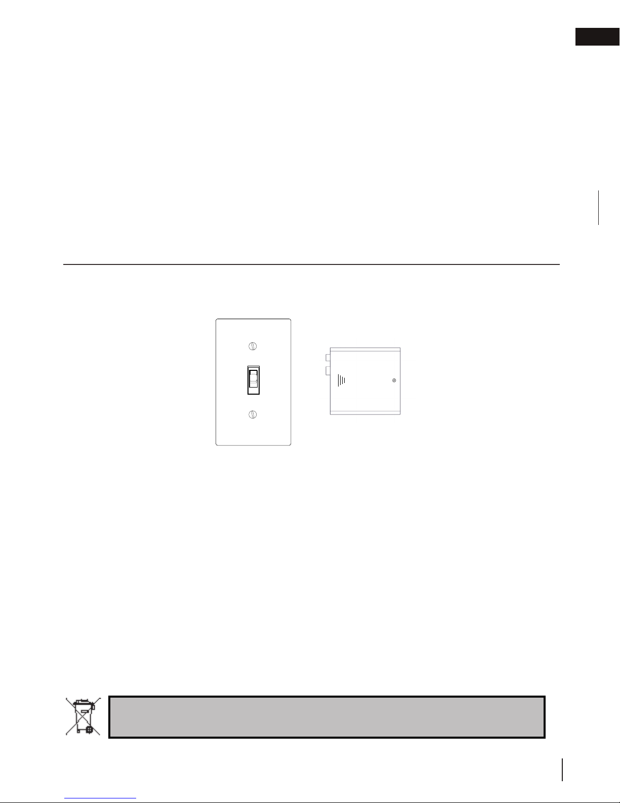
2.2 on/off components
EN
| On/off switch | Battery holder |
(Not supplied)
Batteries must be disposed of according to the local laws and regulations. Some batteries may be
recycled, and may be accepted for disposal at your local recycling center. Check with your
municipality for recycling instructions.
W415-1714 / A / 06.11.18
9
EN
operating your appliance
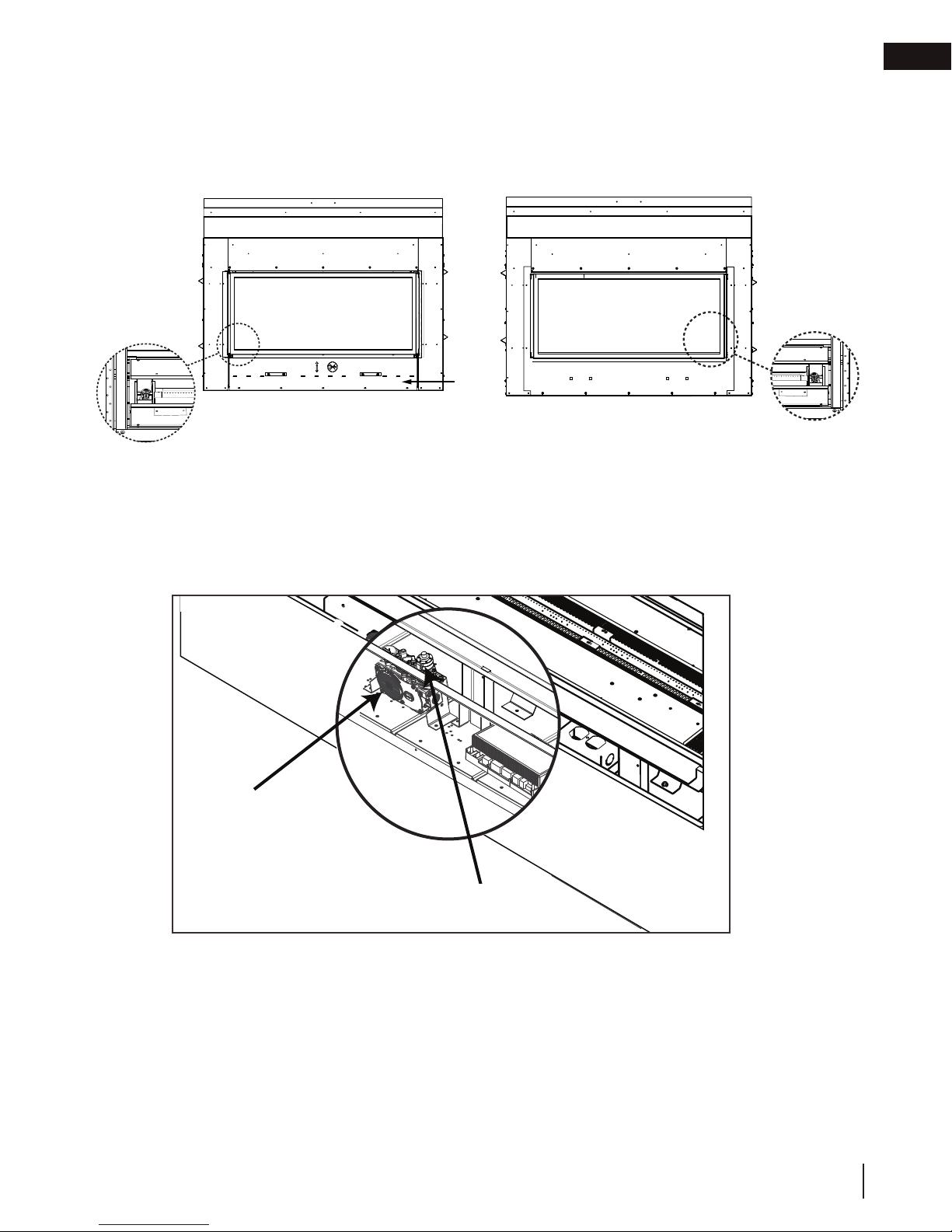
2.2.1 changing the batteries in the battery holder
WARNING
!
• Ensure the gas and electrical power to the appliance is turned off.
• Appliance may be hot, do not service until the appliance has cooled.
note:
In the event of a power failure, your appliance can be operated using the supplied battery back-up. If a power
failure occured, remove the batteries from the holder once the power has been restored.
A. Turn off the gas and disconnect the electrical power supply from the appliance.
B. Remove the safety barrier, control cover and door trim to easily access the control compartment (see
“maintenance” section for instructions on how to remove these components.
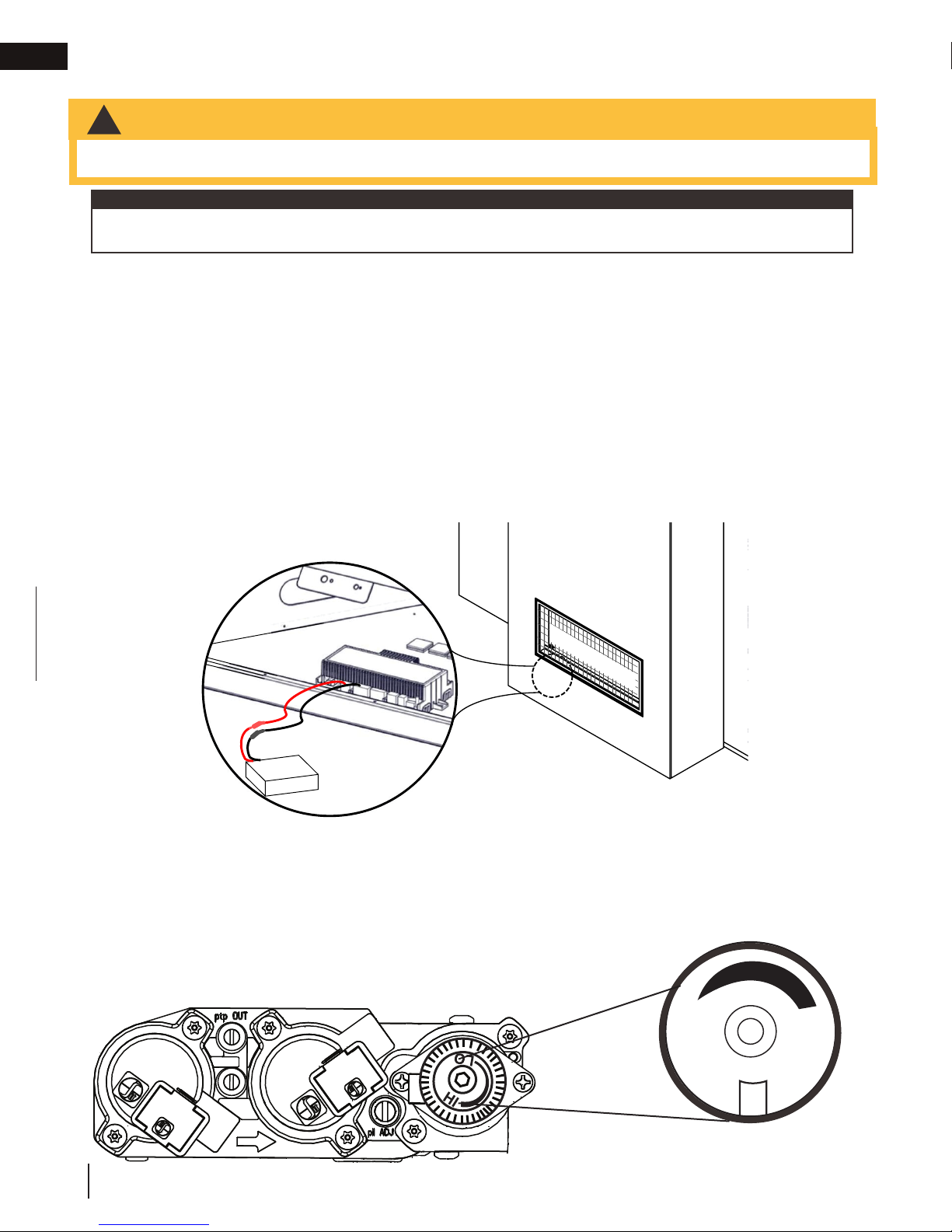
C. Locate the battery housing located near the control board (see illustration below).
D. Open the battery housing by sliding the back piece upwards and off of the battery housing. Remove the
four “AA” alkaline batteries and install four new “AA” alkaline batteries into the battery housing. Ensure the
positive and negative ends correspond with those identified on the holder.
E. Place the battery housing back into the control compartment, ensure that the battery housing is placed in
a clean and easily accessible location.
F. Reinstall the safety barrier. The safety barrier must be installed at all times during the appliance operation.
G. Turn the gas and electrical power back on to begin operating the appliance.
SAFETY BARRIER
Red wire
Black wire
Control module
Battery housing
2.2.2 turndown
Manual adjustments to your appliance must only be made when the appliance is off and complete
cool. Allow safety barrier to cool before making adjustment.
The CL38/CL50 models are equipped with a manual gas control knob (located on the valve) that adjusts the flame
height to suit your preference. To access the gas control knob, remove your safety barrier, control cover and door
trim (see “maintenance” section for instructions on how to remove these components.
Use only your hand to turn the gas control knob (never use tools). If the knob will
not turn by hand, do not try to repair it. Contact a qualified technician.
O
L
H
I
10
W415-1714 / A / 06.11.18
Flame adjustment
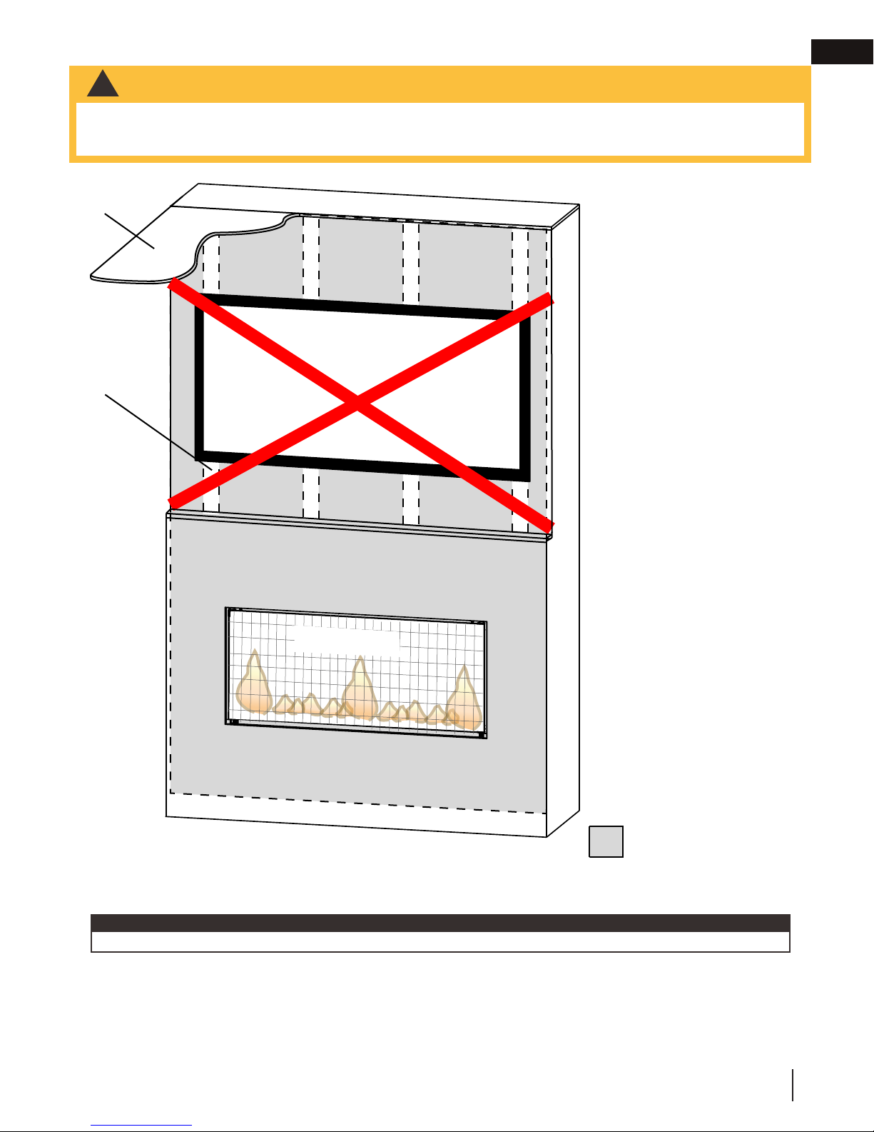
3.0 clearances around appliance
WARNING
!
• Your appliance, gas/electrical connections, venting and various key components are hidden behind the wall. It
is critical that no screws penetrate the areas illustrated below. Failure to follow instructions may cause improper
operation, damage, personal injury or fire. Always use a stud finder and only screw into studs.
Dynamic Heat Control™
EN
Ceiling
Stud
Safety Barrier
The temperatures above the
appliance for CL models will
be hot, making it unsuitable
for mounting a TV or other
objects sensitive to heat
above the appliance without
risk of damage.
Installing a mantel
between this appliance and
electronics or other materials
that may be sensitive to
heat will reduce the effect of
direct heat on them.
The size and material of
the mantel will affect the
allowable clearance above
your appliance and incorrect
placement could become
a fire hazard. Consult your
installation manual and/or
authorized dealer for more
information.
Your appliance, gas/electrical
connections and vent are
hidden directly behind the
finished wall. Great care
should be taken to avoid
screwing or nailing into these
components. Always use a
stud finder to determine stud
location and only screw into
studs.
important:
If in doubt, refer to your installation manual and/or contact your authorized dealer.
(L illustrated)
Do not screw into the
area around the appliance
opening.
No screws
in this area.
W415-1714 / A / 06.11.18
11

EN
4.0 maintenance
maintenance
WARNING
!
• Turn off the gas and electrical power before servicing the appliance.
• Appliance may be hot. Do not service until appliance has cooled.
For qualified technicians only:
• Label all wires prior to disconnection when servicing controls. Wiring errors can cause improper and dangerous
operation. Verify proper operation after servicing.
• This appliance and its venting system should be inspected before use and at least annually by a qualified service
person.
• The flow of combustion and ventilation air must not be obstructed.
DOS
• Clean your safety barrier or regularly to prevent
the build up of excessive lint/dust from carpeting,
pet hair, etc. Simply vacuum using the brush
attachment.
• Always use ammonia-free glass cleaners.
• Service your appliance annually and/or as
required. Service must be conducted by a qualified
technician.
• Keep your appliance area clear and free of
combustible materials, gasoline, or other flammable
vapors and liquids.
• Check to see that the burner ignites completely
on all openings when turned on. A 5 to 10 second
total light-up period is satisfactory. Service as
required.
note:
For any questions and/or concerns regarding your appliance, maintenance and service, please contact your
authorized dealer.
DON’TS
• Attempt to service the electrical or gas
components. Contact a qualified technician.
• Use excessive force.
• Use abrasive cleaners on glass.
• Paint the pilot assembly.
• Place objects too close to the appliance opening.
12
W415-1714 / A / 06.11.18
!
WARNING
Buff lightly with a clean dry soft cloth to remove accumulated dust or fi ngerprints. Clean both sides of the glass
DO NOT SUBSTITUTE MATERIALS.
• Do not clean glass when hot! Do not use abrasive cleaners to clean glass.
4.1 care of glass
WARNING
!
• Do not clean glass when hot! Do not use abrasive cleaners to clean glass.
Firebox Glass Door :
Do not use ammonia-based cleaners.
maintenance
EN
after the fi rst 10 hours of operation with an ammonia-free glass cleaner.
note:
Vinegar-based glass cleaners have demonstrated an ability to provide a clean, streak free glass surface.
Thereafter, clean as required. If the glass is not kept clean permanent discoloration and / or blemishes may
result. Contact you local authorized dealer / distributor for complete cleaning instructions.
Razor blades, steel wool, or other metallic objects must not be used on both surfaces of the glass. Doing so
can remove a thin layer of metal from the razor blades, steel wool, or other metallic objects that may then be
deposited onto the coating. This can result in a discoloured stain or scratch-like mark. More importantly, this can
scratch the glass surface, thereby reducing its strength.
Do not operate the appliance with broken glass, as leakage of fl ue gases may result.
Contact your local authorized dealer / distributor for complete cleaning instructions.
If the glass should ever crack or break while the fi re is burning, do not open the door until the fi re is out. Do not
operate the appliance until the glass has been replaced. Contact you local authorized dealer / distributor for
replacement parts.
Replacement glass/frame assembly shall be replaced as a complete unit as supplied by the appliance
manufacturer.
This appliance is factory equipped with tempered glass. Use only replacement parts as supplied by the appliance
manufacturer. DO NOT SUBSTITUTE MATERIALS.
FOR SEE-THRU MODELS, REPEAT THE STEPS ABOVE ON THE FIXED SIDE. TO CLEAN THE INNER
SIDE OF THE GLASS DOOR ON THE FIXED SIDE, GO THROUGH THE ACCESS SIDE DOOR AND
4
CLEAN AS REQUIRED.
Illustration shows view from access side after access side firebox glass door removed.
access side
fixed side
W415-1714 / A / 06.11.18
13
EN
If the appliance is equipped with plated parts, you must clean fi ngerprints or other marks from the plated surfaces
maintenance
4.2 care of plated parts
before operating the appliance for the fi rst time. Use an ammonia-free or vinegar-based cleaner and a towel
to clean. If not cleaned properly before operating for the fi rst time, the marks can cause permanent blemishes
on the plating. After the plating is cured, the fi ngerprints and oils will not affect the fi nish and little maintenance
is required, just wipe clean as needed. Prolonged high temperature burning with the door ajar may cause
discolouration on plated parts.
note:
The protective wrap on plated parts is best removed when the assembly is at room temperature but this can
be improved if the assembly is warmed (i.e. using a hair dryer or similar heat source).
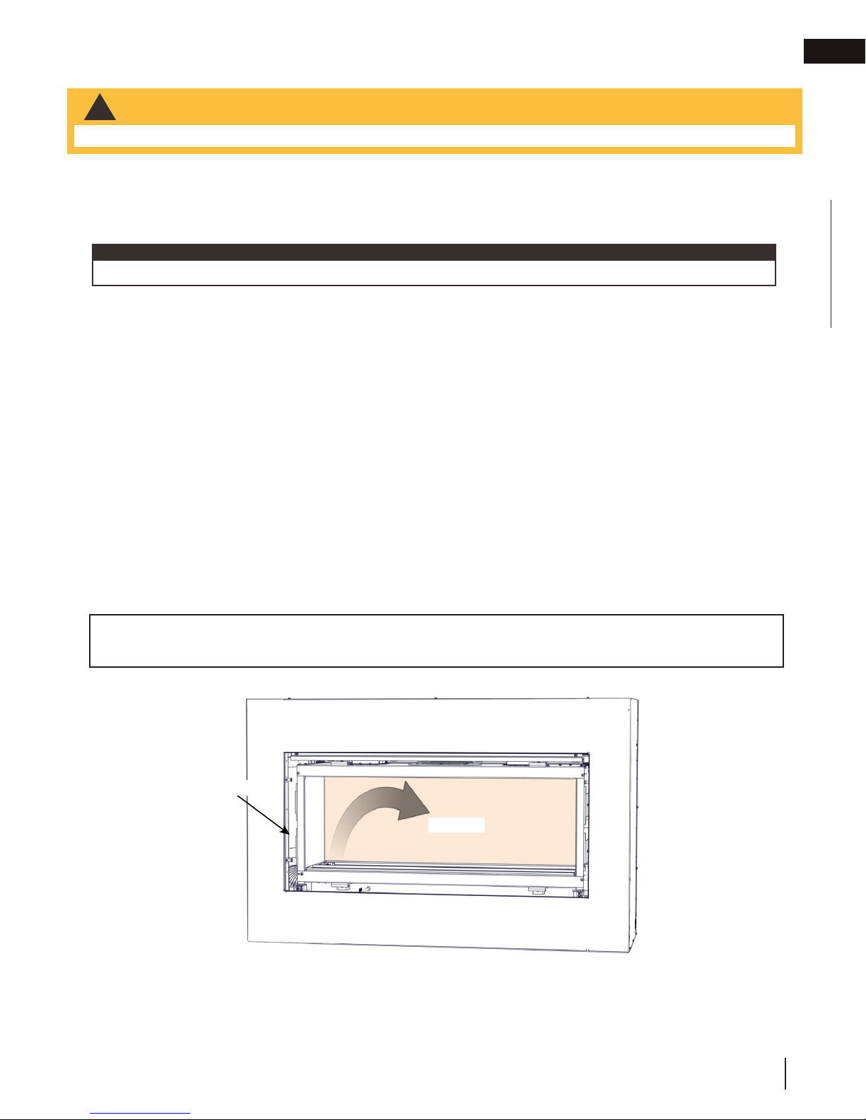
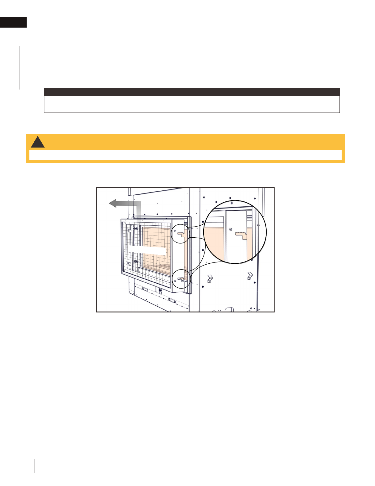
4.3 safety barrier removal
WARNING
!
• Allow appliance to cool completely before proceeding.
A. Lift the safety barrier up and out to disengage the four hooks. Reverse steps to install.
SAFETY BARRIER
14
W415-1714 / A / 06.11.18
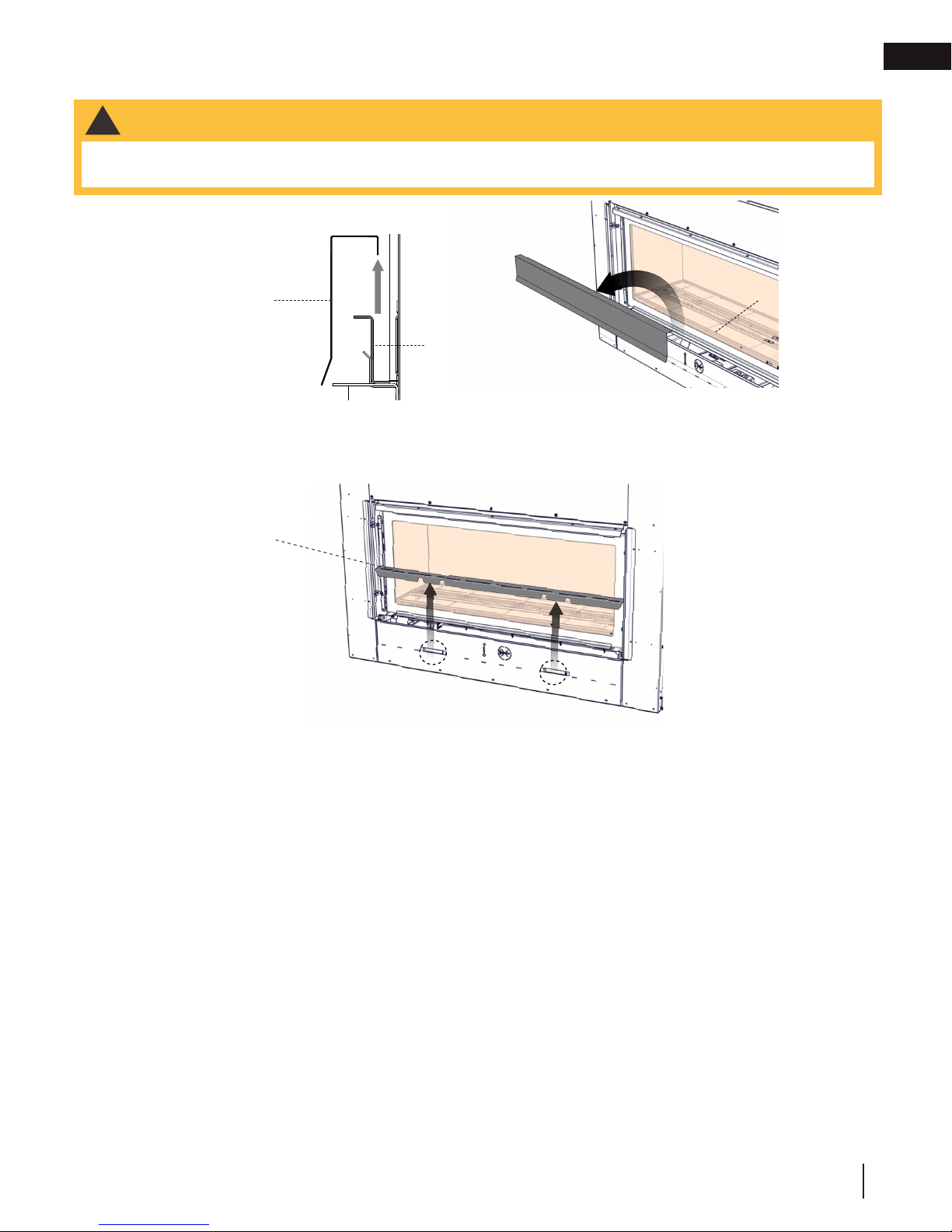
maintenance
4.4 door trim removal
WARNING
!
• Do not insert fingers in the gap between the door and the framing edge, there is a risk of injury due to the
spring mechanism.
EN
FRONT - ACCESS SIDE
Door trim
A. Remove the door trim by carefully lifting it up and off from behind the bottom frame of the glass door.
B. Remove the control cover from the appliance by sliding it up and out of the clips of the front cover.
Control
cover
Side view
Door trim
Door frame
CL38 Illustrated
W415-1714 / A / 06.11.18
15
 Loading...