

Continental Fireplaces CHDX40NT, CHDX40PT Installation And Operating Instructions Manual
INSTALLER: LEAVE THIS MANUAL WITH THE APPLIANCE.
CONSUMER: RETAIN THIS MANUAL FOR FUTURE REFERENCE.
INSTALLATION AND
OPERATING INSTRUCTIONS
CERTIFIED UNDER CANADIAN AND AMERICAN NATIONAL STANDARDS: CSA 2.33, ANSI Z21.88 FOR VENTED GAS FIREPLACE HEATERS.
CHDX40NT
NATURAL GAS
1
CHDX40PT
PROPANE
CERTIFIED FOR CANADA AND UNITED STATES USING ANSI/CSA METHODS.
SAFETY INFORMATION
!
WARNING
If the information in these instructions are
not followed exactly, a fi re or explosion
may result causing property damage,
personal injury or loss of life.
- Do not store or use gasoline or other fl ammable
vapors and liquids in the vicinity of this or any
other appliance.
- WHAT TO DO IF YOU SMELL GAS:
• Do not try to light any appliance.
• Do not touch any electrical switch; do not use
any phone in your building.
• Immediately call your gas supplier from a
neighbour’s phone. Follow the gas supplier’s
instructions.
• If you cannot reach your gas supplier, call the
fi re department.
- Installation and service must be performed by a
qualifi ed installer, service agency or the supplier.
CERTIFIED
Wolf Steel Ltd., 24 Napoleon Rd., Barrie, ON, L4M 4Y8 Canada /
Phone (705)721-1212 • Fax (705)722-6031 • www.continentalfi replaces.com • ask@continentalfi re.on.ca
$10.00
103 Miller Drive, Crittenden, Kentucky, USA, 41030
1.8
W415-0889 / A / 08.11.10

2
TABLE OF CONTENTS
1.0 INSTALLATION OVERVIEW 3
2.0 INTRODUCTION 4
2.1 DIMENSIONS 5
2.2 GENERAL INSTRUCTIONS 5
2.3 GENERAL INFORMATION 6
2.4 RATING PLATE INFORMATION 7
3.0 VENTING 8
3.1 VENTING LENGTHS AND COMPONENTS 8
3.2 TYPICAL VENT INSTALLATIONS 10
3.3 SPECIAL VENT INSTALLATIONS 11
3.3.1 PERISCOPE TERMINATION 11
3.3.2 CORNER TERMINATION 11
3.4 VENT TERMINAL CLEARANCES 12
3.5 VENT APPLICATION FLOW CHART 13
3.6 DEFINITIONS 13
3.7 ELBOW VENT LENGTH VALUES 13
3.8 HORIZONTAL TERMINATION 14
3.9 VERTICAL TERMINATION 16
4.0 INSTALLATION 18
4.1 WALL AND CEILING PROTECTION 18
4.1.1 HORIZONTAL INSTALLATION 19
4.1.2 VERTICAL INSTALLATION 19
4.2 USING FLEXIBLE VENT COMPONENTS 20
4.2.1 HORIZONTAL AIR TERMINAL INSTALLATION 20
4.2.2 VERTICAL AIR TERMINAL INSTALLATION 21
4.3 MOBILE HOME 22
4.4 ACCESS PANEL FOR GAS LINE CONNECTION 22
4.5 GAS INSTALLATION 23
5.0 FRAMING 24
5.1 MINIMUM CLEARANCE TO COMBUSTIBLES 26
5.2 MINIMUM CLEARANCE TO COMBUSTIBLE ENCLOSURES 27
5.3 MINIMUM MANTEL CLEARANCES 29
6.0 FINISHING 30
6.1 DOOR REMOVAL / INSTALLATION 30
6.2 LOG PLACEMENT 31
6.3 GLOWING EMBER PLACEMENT 32
6.4 LAVA ROCK 32
6.5 OPTIONAL ROCK PLACEMENT 33
6.6 LOGO PLACEMENT 34
7.0 OPTIONAL BLOWER INSTALLATION 35
7.1 ACCESSING THE BLOWER 35
7.2 INSTALLING THE BLOWER 36
8.0 WIRING DIAGRAM / ELECTRICAL INFORMATION 37
8.1 WIRING REQUIREMENTS 37
8.2 OPTIONAL ACCESSORIES REQUIREMENTS 37
8.3 JUNCTION BOX INSTALLATION 38
8.4 WIRING DIAGRAM 39
9.0 OPERATION 40
10.0 ADJUSTMENT 41
10.1 PRESSURE ADJUSTMENT 41
10.2 VENTURI ADJUSTMENT 41
10.3 FLAME ADJUSTMENT 41
10.4 FLAME CHARACTERISTICS 42
11.0 MAINTENANCE 42
11.1 LAMP REPLACEMENT 43
11.2 DOOR GLASS REPLACEMENT 44
11.3 CARE OF GLASS 44
11.4 CARE OF PLATED PARTS 44
12.0 REPLACEMENT PARTS 45
13.0 TROUBLESHOOTING 48
14.0 WARRANTY 50
15.0 SERVICE HISTORY 51
NOTE: Changes, other than editorial, are denoted by a vertical line in the margin.
W415-0889 / A / 08.11.10
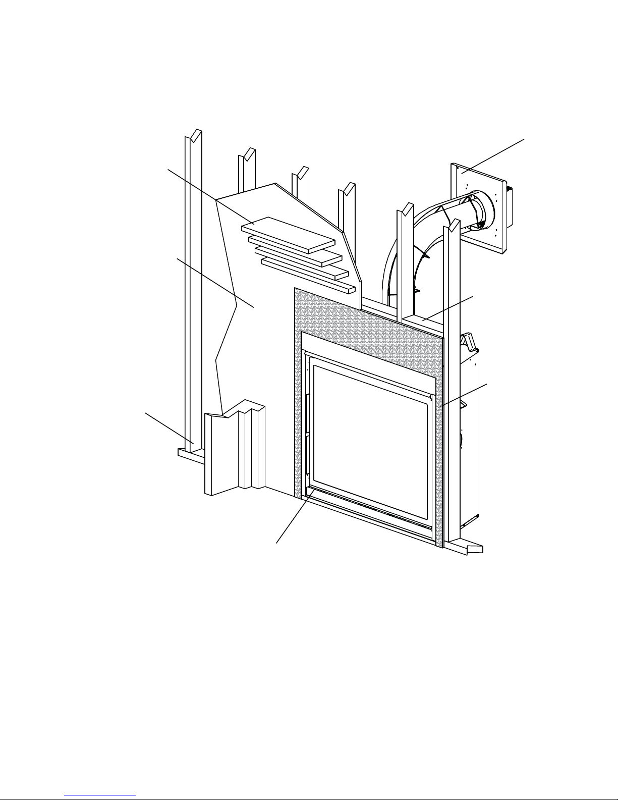
1.0 INSTALLATION OVERVIEW
3
Mantel, see “MINIMUM MANTEL
CLEARANCES”
section.
Enclosures, see the
section “MINIMUM
CLEARANCES TO
COMBUSTIBLE
ENCLOSURES”
section for drywall (or
other combustible
material).
Framing, see
“FRAMING”
section.
Side
Wall
Venting, see “VENTING”
section.
Framing, see “FRAMING”
section.
Enclosures, see the
section “MINIMUM
CLEARANCE TO
COMBUSTIBLE
ENCLOSURES”
section for
non-combustible
materials such as
tile, marble, granite,
etc.
Rating plate, see “RATING
PLATE INFORMATION”
section.
W415-0889 / A / 08.11.10
4
2.0 INTRODUCTION
• THIS APPLIANCE IS HOT WHEN OPERATED AND CAN CAUSE SEVERE BURNS IF CONTACTED.
• ANY CHANGES OR ALTERATIONS TO THIS APPLIANCE OR ITS CONTROLS CAN BE
DANGEROUS AND IS PROHIBITED.
• Do not operate appliance before reading and understanding operating instructions. Failure to operate
appliance according to operating instructions could cause fi re or injury.
• Risk of fi re or asphyxiation do not operate appliance with fi xed glass removed.
• Do not connect 110 volts to the control valve.
• Risk of burns. The appliance should be turned off and cooled before servicing.
• Do not install damaged, incomplete or substitute components.
• Risk of cuts and abrasions. Wear protective gloves and safety glasses during installation. Sheet metal
edges may be sharp.
• Do not burn wood or other materials in this appliance.
• Young children should be carefully supervised when they are in the same room as the appliance.
Toddlers, young children and others may be susceptible to accidental contact burns. A physical barrier
is recommended if there are at risk individuals in the house. To restrict access to an appliance or stove,
install an adjustable safety gate to keep toddlers, young children and other at risk individuals out of the
room and away from hot surfaces.
• Clothing or other fl ammable material should not be placed on or near the appliance.
• Due to high temperatures, the appliance should be located out of traffi c and away from furniture and
draperies.
• Ensure you have incorporated adequate safety measure to protect infants/toddlers from touching hot
surfaces.
• Even after the appliance is out, the glass and/or screen will remain hot for an extended period of time.
• Check with your local hearth specialty dealer for safety screens and hearth guards to protect children
from hot surfaces. These screens and guards must be fastened to the fl oor.
• Any safety screen or guard removed for servicing must be replaced prior to operating the appliance.
• The appliance is a vented gas-fi red appliance. Do not burn wood or other materials in the appliance
• It is imperative that the control compartments, burners and circulating blower and its passageway in the
appliance and venting system are kept clean. The appliance and its venting system should be inspected
before use and at least annually by a qualifi ed service person. More frequent cleaning may be required
due to excessive lint from carpeting, bedding material, etc. The appliance area must be kept clear and
free from combustible materials, gasoline and other fl ammable vapors and liquids.
• Under no circumstances should this appliance be modifi ed.
• This appliance must not be connected to a chimney fl ue pipe serving a separate solid fuel burning
appliance.
• Do not use this appliance if any part has been under water. Immediately call a qualifi ed service
technician to inspect the appliance and to replace any part of the control system and any gas control
which has been under water.
• Do not operate the appliance with the glass door removed, cracked or broken. Replacement of the glass
should be done by a licensed or qualifi ed service person.
• Do not strike or slam shut the appliance glass door.
• When equipped with pressure relief doors, they must be kept closed while the appliance is operating
to prevent exhaust fumes containing carbon monoxide, from entering into the home. Temperatures of
the exhaust escaping through these openings can also cause the surrounding combustible materials to
overheat and catch fi re.
• Only doors / optional fronts certifi ed with the unit are to be installed on the appliance.
• Keep the packaging material out of reach of children and dispose of the material in a safe manner. As
with all plastic bags, these are not toys and should be kept away from children and infants.
• As with any combustion appliance, we recommend having your appliance regularly inspected and
serviced as well as having a Carbon Monoxide Detector installed in the same area to defend you and
your family against Carbon Monoxide.
• Ensure clearances to combustibles are maintained when building a mantel or shelves above the
appliance. Elevated temperatures on the wall or in the air above the appliance can cause melting,
discolouration or damage of decorations, a T.V. or other electronic components.
W415-0889 / A / 08.11.10
!
WARNING
3.2A
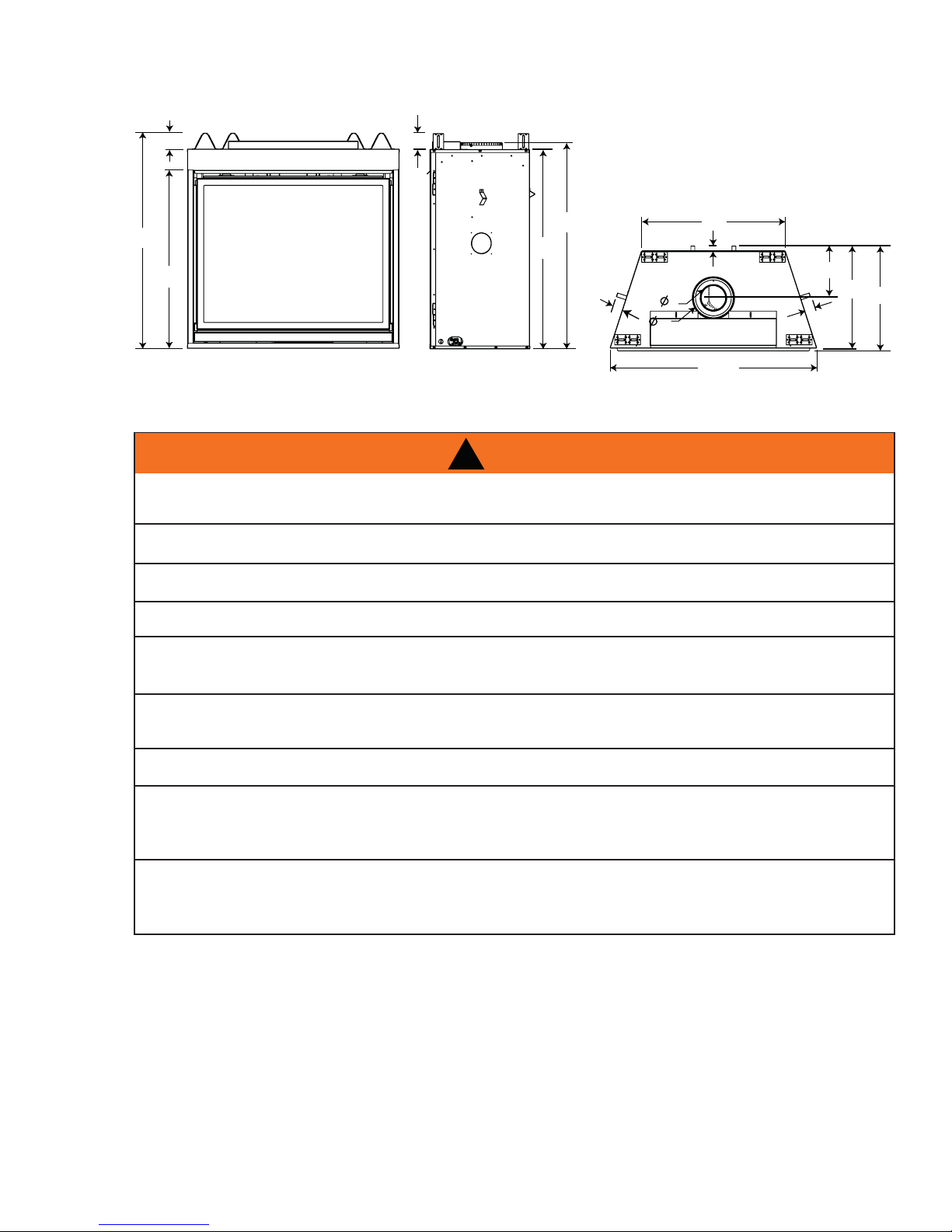
2.1 DIMENSIONS
5
3”
41”
33 ¾”
2.2 GENERAL INSTRUCTIONS
ALWAYS LIGHT THE PILOT WHETHER FOR THE FIRST TIME OR IF THE GAS SUPPLY HAS RAN OUT,
WITH THE GLASS DOOR OPENED OR REMOVED.
PROVIDE ADEQUATE CLEARANCE FOR SERVICING AND OPERATING THE APPLIANCE.
3”
39 ¼”
38”
2"
!
WARNING
PROVIDE ADEQUA TE VENTILA TION.
28”
1"
10 ³/16”
20”
5"
8"
40 ¼”
2"
20 ½”
NEVER OBSTRUCT THE FRONT OPENING OF THE APPLIANCE.
OBJECTS PLACED IN FRONT OF THE APPLIANCE MUST BE KEPT A MINIMUM OF 48” FROM THE
FRONT FACE OF THE UNIT.
SURFACES AROUND AND ESPECIALLY ABOVE THE APPLIANCE CAN BECOME HOT. AVOID CONTACT
WHEN THE APPLIANCE IS OPERATING.
FIRE RISK. EXPLOSION HAZARD.
HIGH PRESSURE WILL DAMAGE VALVE. DISCONNECT GAS SUPPLY PIPING BEFORE PRESSURE TESTING
GAS LINE AT TEST PRESSURES ABOVE 1/2 PSIG. CLOSE THE MANUAL SHUT-OFF VALVE BEFORE
PRESSURE TESTING GAS LINE AT TEST PRESSURES EQUAL TO OR LESS THAN 1/2 PSIG.
USE ONLY WOLF STEEL APPROVED OPTIONAL ACCESSORIES AND REPLACEMENT PARTS WITH THIS APPLIANCE.
USING NON-LISTED ACCESSORIES (BLOWERS, DOORS, LOUVRES, TRIMS, GAS COMPONENTS, VENTING
COMPONENTS, ETC.) COULD RESULT IN A SAFETY HAZARD AND WILL VOID THE WARRANTY AND CERTIFICATION.
THIS GAS APPLIANCE SHOULD BE INSTALLED AND SERVICED BY A QUALIFIED INSTALLER to
conform with local codes. Installation practices vary from region to region and it is important to know the
specifi cs that apply to your area, for example in Massachusetts State:
• This product must be installed by a licensed plumber or gas fi tter when installed within the commonwealth
of Massachusetts.
• The appliance damper must be removed or welded in the open position prior to installation of a appliance
insert or gas log.
• The appliance off valve must be a “T” handle gas cock.
• The fl exible connector must not be longer than 36 inches.
• A Carbon Monoxide detector is required in all rooms containing gas fi red appliances.
• The appliance is not approved for installation in a bedroom or bathroom unless the unit is a direct vent
sealed combustion product.
W415-0889 / A / 08.11.10
6
A
A
The installation must conform with local codes or, in
absence of local codes, the National Gas and Propane
Installation Code CSA B149.1 in Canada, or the National
Fuel Gas Code, ANSI Z223.1 / NFPA 54 in the United
States. Suitable for mobile home installation if installed in
accordance with the current standard CAN/CSA Z240MH
Series, for gas equipped mobile homes, in Canada or
NSI Z223.1 and NFPA 54 in the United States.
www.ncertied.org
s long as the required clearance to combustibles is
maintained, the most desirable and benefi cial location for an appliance is in the center of a building, thereby
allowing the most effi cient use of the heat created. The location of windows, doors and the traffi c fl ow in the
room where the appliance is to be located should be considered. If possible, you should choose a location
where the vent will pass through the house without cutting a fl oor or roof joist.
If the appliance is installed directly on carpeting, vinyl tile or other combustible material other than wood
fl ooring, the appliance shall be installed on a metal or wood panel extending the full width and depth.
If the optional fan or blower is installed, the junction box must be electrically connected and grounded in
accordance with local codes, use the current CSA C22.1 Canadian Electrical Code in Canada or the ANSI/
NFPA 70 National Electrical code in the United States.
This appliance is equipped with a power back up control system. Two 1.5 volt “D” batteries (not supplied) are
required for the battery pack included in the system. Use Alkaline batteries only.
We suggest that our gas
hearth products be installed
and serviced by professionals
who are certied in the U.S.
by the National Fireplace
®
Institute
(NFI) as NFI Gas
Specialists
4.1
2.3 GENERAL INFORMATION
FOR YOUR SATISFACTION, THIS APPLIANCE HAS BEEN TEST-FIRED TO ASSURE ITS OPERATION
AND QUALITY!
This appliance is approved for bathroom, bedroom and bed-sitting room installations and is suitable for mobile
home installations.
This appliance is equipped with ceramic glass. Replacement glass must be obtained from your authorized
dealer / distributor and is identifi ed in the replacement parts list. Do not substitute materials.
This appliance is not convertible for use with other gases, unless a certifi ed kit is used.
Expansion / contraction noises during heating up and cooling down cycles are normal and are to be expected.
Changes in fl ame appearance from “HI” to “LO” is more evident in natural gas than in propane.
Use only accessories designed for and listed with your specifi c appliance.
High Elevations
Input ratings are shown in BTU per hour and are certifi ed without de-rating up to 4,500 feet above sea level. For In-
stallations at the elevations above 4,500 feet and in the absence of specifi c recommendations from the local author-
ity having jurisdiction, the high altitude input rating shall be reduced at the rate of 4% for each additional 1,000 feet.
GAS SPECIFICATIONS
Model Fuel Gas
Control
CHDX40NT Nat IPI Hi/Lo 40,000 26,000
CHDX40PT Prop* IPI Hi/Lo 36,000 26,000
IPI - Intermittent Pilot Ignition System
* Using conversion kit
** Maximum Values
Conversions must be made by a qualifi ed service technician
using Wolf Steel specifi ed and approved parts.
Max.
Input
BTU/h
Min.
Input
BTU/h
Minimum Inlet 4.5” w.c. 11.0” w.c.
Maximum Inlet 7.0” w.c. 13.0” w.c.
Manifold Pressure 3.5” w.c. 10.0” w.c.
CHDX40NT 61.5% 59.5%
CHDX40PT 61.5% 59.5%
GAS INLET AND MANIFOLD
PRESSURES
Natural Propane
EFFICIENCY RATINGS
Model Steady
State(%)
AFUE%**
W415-0889 / A / 08.11.10
2.4 RATING PLATE INFORMATION
UMNUMN
COLUMNCOLUMN
TER COLUMNTER COLU
COLONNE D'EAUCOLONNE D'EA
FOR USEFOR USE
WITH
ANCE,
CHCH
LWIL
LL
COMECOME
NIN
UANU
FF
ACTURERACTURER
MMAATERIALS /TERIALS /
PTH / PROFONDEUR D'ENCASTREFONDEUR D'ENCASTRE
/ COTES DE L'EVEN'EVEN
TT
/ DESSUS DE L’ÉVEN / DESSUS DE L’ÉVEN
OTOTTTOM /
SSOUS
NOM / DESSOUS DE L’ÉVEN
T
TENSION / EXTENSION HORIZON
TT
OFOREGRE
AATETE
EEXTE
FOR MINIMUM FOR MINIMUM
ANDANATIONTIONDUDU
:PRESSURE:
NPRESSION
UA
MMINIMUM
P
Y
NPRESSI
D
MMAXIMUM
D DVVAA
TIONTION
TIONTION
ATA
TION REDUITETION REDUITE
500
TT
(0-1 (0-
26,00026,000
X40PT
À
À
ME DE SÉCURITÉ ET DE CONME DE SÉCURITÉ ET DE CON
,,
T ÊTRE APPLIQUÉE, SE RÉFÉRE
,,,
,,
,,
7
DIRECT VENT GAS FIREPLACE HEATER. SUITABLE FOR BEDROOM, BATHROOM AND
BED-SITTING ROOM INSTALLATION. SUITABLE FOR MOBILE HOME INSTALLATION
IF INSTALLED IN ACCORDANCE WITH THE CURRENT STANDARD CAN/CSA
Z240MH SERIES GAS EQUIPPED MOBILE HOMES, IN CANADA OR IN THE UNITED
STATES THE MANUFACTURED HOME CONTRUCTION AND SAFETY STANDARD,
TITLE 24 CFR, PART 3280. WHEN THIS US STANDARD IS NOT APPLICABLE
USE THE STANDARD FOR FIRE SAFETY CRITERIA FOR MANUFACTURED
HOME INSTALLATIONS, SITES AND COMMUNITIES, ANSI / NFPA 501A. WHEN
INSTALLED WITH SCREEN KIT GD-565KT, THE FIREPLACE COMPLIES WITH
CGA CERTIFICATION REQUIREMENT CR95-006.
THIS VENT ED GA S F IR E PL AC E H EA TE R I S N O T F OR US E WITH
AIR FILTERS AND NOT FOR USE WITH SOLID FUEL. FOR USE
WITH GLASS DOORS CERTIFIED WITH THIS UNIT ONLY
WARNING: DO NOT ADD ANY MATERIAL TO THE APPLIANCE, WHICH WILL COME IN
CONTACT WITH THE FLAMES, OTHER THAN THAT SUPPLIED BY THE MANUFACTURER
WITH THE APPLIANCE.
MINIMUM CLEARANCE TO COMBUSTIBLE MATERIALS /
DEGAGEMENTS MINIMAUX DES MATERIAUX COMBUSTIBLES:
TOP/ DESSUS 6½" RECESSED DEPTH / PROFONDEUR D'ENCASTRE 20½"
FLOOR / PLANCHER 0 VENT SIDES / COTES DE L'EVENT 2"
SIDES / COTES 2”
BACK / ARRIERE 1”
MANTLE / MANTEAU 13"
* MAXIMUM HORIZONTAL EXTENSION / EXTENSION HORIZONTALE MAXIMALE: 2".
SEE INSTRUCTION MANUAL FOR GREATER EXTENSIONS. SE RÉFÉRER AU
MANUEL
SEE OWNER'S INSTRUCTION MANUAL FOR MINIMUM AND MAXIMUM VENT LENGTHS.
SE RÉFÉRER AU MANUEL D'INSTALLATION DU PROPRIÉTAIRE POUR LES LONGUEURS
D'EVACUATION MINIMALE ET MAXIMALE.
CERTIFIED UNDER / HOMOLOGUÉ SELON LES NORMES: CSA 2.22b-2009, ANSI Z21.50b-2009 VENTED GAS FIREPLACE / APPAREIL À GA Z V E N T I L É S .
CERTIFIED
TIFIED FOR
R
CE
CERTIFIEE POUR
HDX40NT
Natural Gas/Gaz Naturel
CHDX40NT
0-4500 FT (0-1370m)
40,000 BTU/h
26,000 BTU/h
PRESSION AU COLLECTEUR: 3.5" D'UNE COLONNE D'EAU
PRESSION D'ALIMENTATION MINIMALE: 4.5" D'UNE COLONNE D'EAU
PRESSION D'ALIMENTATION MAXIMALE: 7.0" D'UNE COLONNE D'EAU
MANIFOLD PRESSURE: 3.5" WATER COLUMN
MINIMUM SUPPLY PRESSURE: 4.5" WATER COLUMN
MAXIMUM SUPPLY PRESSURE: 7.0" WATER COLUMN
REDUCED INPUT / ALIMENTATION REDUITE
CANADA USA
REFERENCE # 161746
MODEL
ALTITUDE / ELEVATION
INPUT / ALIMENTATION
T
MANIFOLD PRESSURE: 10" WATER COLUMN
ANIFOL
PRESSION AU COLLECTEUR: 10" D'UNE COLONNE D'EAU
RESSIO
MINIMUM SUPPLY PRESSURE: 11" WATER COLUMN
INIMU
PRESSION D'ALIMENTATION MINIMALE: 11" D'UNE COLONNE D'EAU
RESSIO
MAXIMUM SUPPLY PRESSURE: 13" WATER COLUMN
AXIMU
PRESSION D'ALIMENTATION MAXIMALE: 13" D'UNE COLONNE D'EAU
RESSION
CE FOYER À GAZ VENTILÉS NE DOIT PAS ÊTRE UTILISÉ AVEC
WITH
DES FILTRES À AIR ET NE DOIT PAS ÊTRE UTILISÉ AVEC
UN COMBUSTIBLE SOLIDE. UTILISER AVEC LES PORTES
WHI
Y THE MAN
VENT TOP / DESSUS DE L’ÉVENT 2"
VENT BOTTOM / DESSOUS DE L’ÉVENT 1"
*
D'INSTRUCTION POUR DES EXTENSIONS PLUS GRANDES.
DE
DE L’ÉVE
F
EXT
WI
VITRÉES HOMOLOGUÉES AVEC CETTE UNITÉ SEULEMENT.
I
AVERTISSEMENT: N'A JOUTEZ PAS A CET APPAREIL AUCUN MATERIAU DEVANT
ENTRER EN CONTACT A VEC LES FLAMMES AUTRE QUE CELUI QUI EST FOURNI A VEC CET
APPAREIL PAR LE FABRICANT.
THE APPLIANCE MUST BE VENTED USING THE APPROPRIATE WOLF STEEL VENT KITS. SEE OWNERS
INSTALLA TION MANUAL FOR VENTING SPECIFICS. PROPER REINST ALLA TION AND RESEALING IS
NECESSARY AFTER SERVICING THE VENT-AIR INTAKE SYSTEM.
GAZ EN UTILISANT L'ENSEMBLE D'ÉVACUATION PROPRE À
D'INSTALLATION DU PROPRIÉTAIRE POUR LES SPÉCIFICATIONS DE L'ÉVACUATION. IL EST IMPORTANT
DE BIEN RÉINSTALLER ET RESCELLER L'ÉVENT APRÈS AVOIR EFFECTUÉ LE SERVICE DU SYSTÊME DE PRISE D'AIR.
ELECTRICAL RATING / CLASSIFICATION: 115V, 60HZ, LESS THAN 12 AMPS.
SPÉCIFICATIONS ÉLECTRIQUES : 115 V, 60 HZ, MOINS DE 12 A.
OPTIONAL FAN KIT / SOUFFLERIE OPTIONNELLE : GZ550-KT, GD65
SERIAL NUMBER/NO. DE SERIE: HDX40
APPAREIL DE CHAUFFAGE À ÉVACUATION DIRECTE. HOMOLOGUÉ POUR INSTALLATION
DANS UNE CHAMBRE À COUCHER, UNE SALLE DE BAIN ET UN STUDIO. APPROPRIÉ
POUR INSTALLATION DANS UNE MAISON MOBILE SI SON INSTALLATION EST
CONFORME AUX EXIGENCES DE LA NORME CAN/CSA Z240MH SÉRIE DE MAISONS
MOBILES ÉQUIPÉES AU GAZ, EN VIGUEUR AU CANADA, OU AUX ÉTATS-UNIS, SELON
LA NORME DE SÉCURITÉ ET DE CONSTRUCTION DE MAISONS MANUFACTURÉES,
TITRE 24 CFR, SECTION 3280. DANS LE CAS OÙ CETTE NORME DES ÉTATS-UNIS NE
PEUT ÊTRE APPLIQUÉE, SE RÉFÉRER À LA NORME RELATIVE AU CRITÈRE DE
MESURES DE SÉCURITÉ CONTRE L'INCENDIE POUR LES INSTALLATIONS DANS LES
MAISONS MANUFACTURÉES, LES SITES ET LES COMMUNAUTÉS, ANSI/NFPA 501A.
LORSQU'IL EST INSTALLÉ AVEC LE PARE-ÉTINCELLES GD-565KT, LE FOYER EST
RESSURE
A
SUP
24 NAPOLEON ROAD, BARRIE. ONTARIO L4M 4Y8 CANADA
CONFORME À LA NORME DE CERTIFICATION DE L'ACG CR95-006.
F
Propane
CHDX40PT
L'APPAREIL DOIT ÉVACUER SES
WOLF
STEEL. SE RÉFÉRER
HDX40PT
HDX40PT
0-4500FT (0-1370m)
-4
36,000 BTU/h
26,000 BTU/h
WOLF STEEL LTD.
AU MANUEL
W385-0496 / A
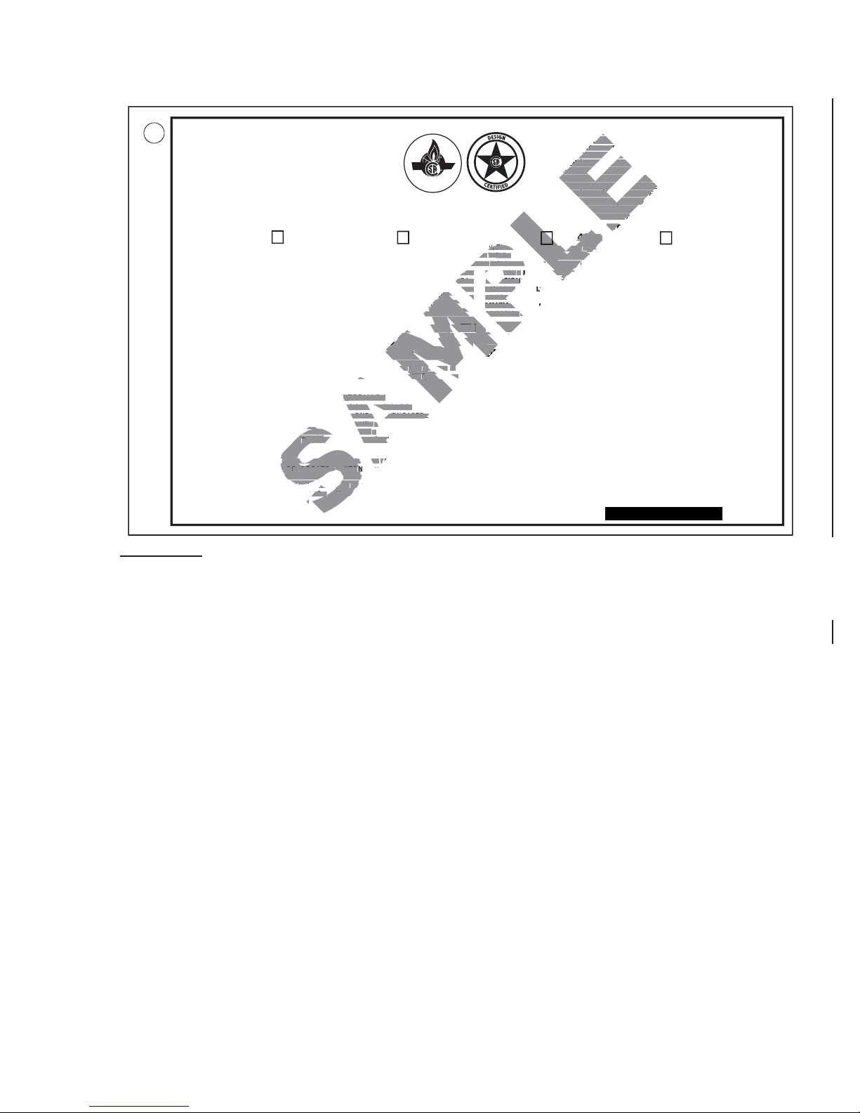
INSTALLER: It is your responsibility to check off the appropriate box on the rating plate according to
the model, venting and gas type of the appliance.
For rating plate location, see “INSTALLATION OVERVIEW” section.
This illustration is for reference only. Refer to the rating plate on the appliance for accurate information.
W415-0889 / A / 08.11.10
8
3.0 VENTING
!
WARNING
RISK OF FIRE, MAINTAIN SPECIFIED AIR SPACE CLEARANCES TO VENT PIPE AND APPLIANCE.
IF VENTING IS INCLUDED WITH SPACERS THE VENT SYSTEM MUST BE SUPPORTED EVERY 3 FEET
FOR BOTH VERTICAL AND HORIZONTAL RUNS. USE SUPPORTS OR EQUIVALENT
NON-COMBUSTIBLE STRAPPING TO MAINTAIN THE REQUIRED CLEARANCE FROM
COMBUSTIBLES. USE WOLF STEEL LTD. SUPPORT RING ASSEMBLY W010-0370 OR EQUIVALENT
NON-COMBUSTIBLE STRAPPING TO MAINTAIN THE MINIMUM CLEARANCE TO COMBUSTIBLES
FOR BOTH VERTICAL AND HORIZONTAL RUNS. SPACERS ARE ATTACHED TO THE INNER PIPE AT
PREDETERMINED INTERVALS TO MAINTAIN AN EVEN AIR GAP TO THE OUTER PIPE. THIS GAP IS
REQUIRED FOR SAFE OPERATION. A SPACER IS REQUIRED AT THE START, MIDDLE AND END OF
EACH ELBOW TO ENSURE THIS GAP IS MAINTAINED. THESE SPACERS MUST NOT BE REMOVED.
THIS APPLIANCE USES A 5” EXHAUST / 8” AIR INTAKE VENT PIPE SYSTEM.
Refer to the section applicable to your installation.
For safe and proper operation of the appliance follow the venting instruction exactly. Deviation from the
minimum vertical vent length can create diffi culty in burner start-up and/or carboning. Under extreme vent
confi gurations, allow several minutes (5-15) for the fl ame to stabilize after ignition. Vent lengths that pass
through unheated spaces (attics, garages, crawl spaces) should be insulated with the insulation wrapped in
a protective sleeve to minimize condensation. Provide a means for visually checking the vent connection to
the appliance after the appliance is installed. Use a fi restop, vent pipe shield or attic insulation shield when
penetrating interior walls, fl oor or ceiling.
NOTE: If for any reason the vent air intake system is disassembled; reinstall per the instructions
provided for the initial installation.
3.1 VENTING LENGTHS AND COMPONENTS
Use only Wolf Steel, Simpson Dura-Vent, Selkirk Direct Temp, American Metal Amerivent or Metal-Fab
venting components. Minimum and maximum vent lengths, for both horizontal and vertical installations, and
air terminal locations for either system are set out in this manual and must be adhered to. For Simpson DuraVent, Selkirk Direct Temp, American Metal Amerivent and Metal-Fab follow the installation procedure provided
with the venting components.
7.2
A starter adaptor must be used with the following vent systems and may be purchased from the
corresponding supplier:
PART 5”/8” SUPPLIER WEBSITE
Duravent W175-0170 Wolf Steel www.duravent.com
Amerivent 5DSC-N2 American Metal www.americanmetalproducts.com
Direct Temp 5DT-AA Selkirk www.selkirkcorp.com
SuperSeal 5DDA Metal-Fab www.mtlfab.com
For Simpson Dura-Vent, Selkirk Direct Temp, American Metal Amerivent and Metal-Fab follow the installation
procedure found on the website for your venting supplier.
For vent systems that provide seals on the inner exhaust fl ue, only the outer air intake joints must be sealed using a
red high temperature silicone (RTV). This same sealant may be used on both the inner exhaust and outer intake vent
pipe joints of all other approved vent systems except for the exhaust vent pipe connection to the appliance fl ue collar
which must be sealed using the black high temperature sealant Mill Pac.
When using Wolf Steel venting components, use only approved Wolf Steel rigid / fl exible components with the following
termination kits: wall terminal kit GD422-1, GD422R-1, or 1/12 to 7/12 pitch roof terminal kit GD410, 8/12 to 12/12 roof
terminal kit GD411, fl at roof terminal kit GD412 or periscope kit GD401 (for wall penetration below grade). With fl exible
venting, in conjunction with the various terminations, use either the 5 foot vent kit GD420 or the 10 foot vent kit GD430.
W415-0889 / A / 08.11.10

9
For optimum fl ame appearance and appliance performance, keep the vent length and number of elbows to a
minimum.
The air terminal must remain unobstructed at all times. Examine the air terminal at least once a year to verify
that it is unobstructed and undamaged.
Rigid and fl exible venting systems must not be combined. Different venting manufacturer components must
not be combined.
These vent kits allow for either horizontal or vertical venting of the appliance. The maximum allowable horizontal run
is 20 feet. The maximum allowable vertical vent length is 40 feet. The maximum number of vent connections is two
horizontally or three vertically (excluding the appliance and the air terminal connections) when using fl exible venting.
Horizontal runs may have a 0” rise per foot however for optimum performance it is recommended that all horizontal
runs have a minimum 1/4” rise per foot using fl exible venting. For safe and proper operation of the appliance, follow
the venting instructions exactly.
A terminal shall not terminate directly above a sidewalk or paved driveway which is located between two single family
dwellings and serves both dwellings. Local codes or regulations may require different clearances.
Do not allow the inside liner to bunch up on horizontal or vertical runs and elbows. Keep it pulled tight. A 1¼” air gap
all around between the inner liner and outer liner is required for safe operation.
8.3
W415-0889 / A / 08.11.10
10
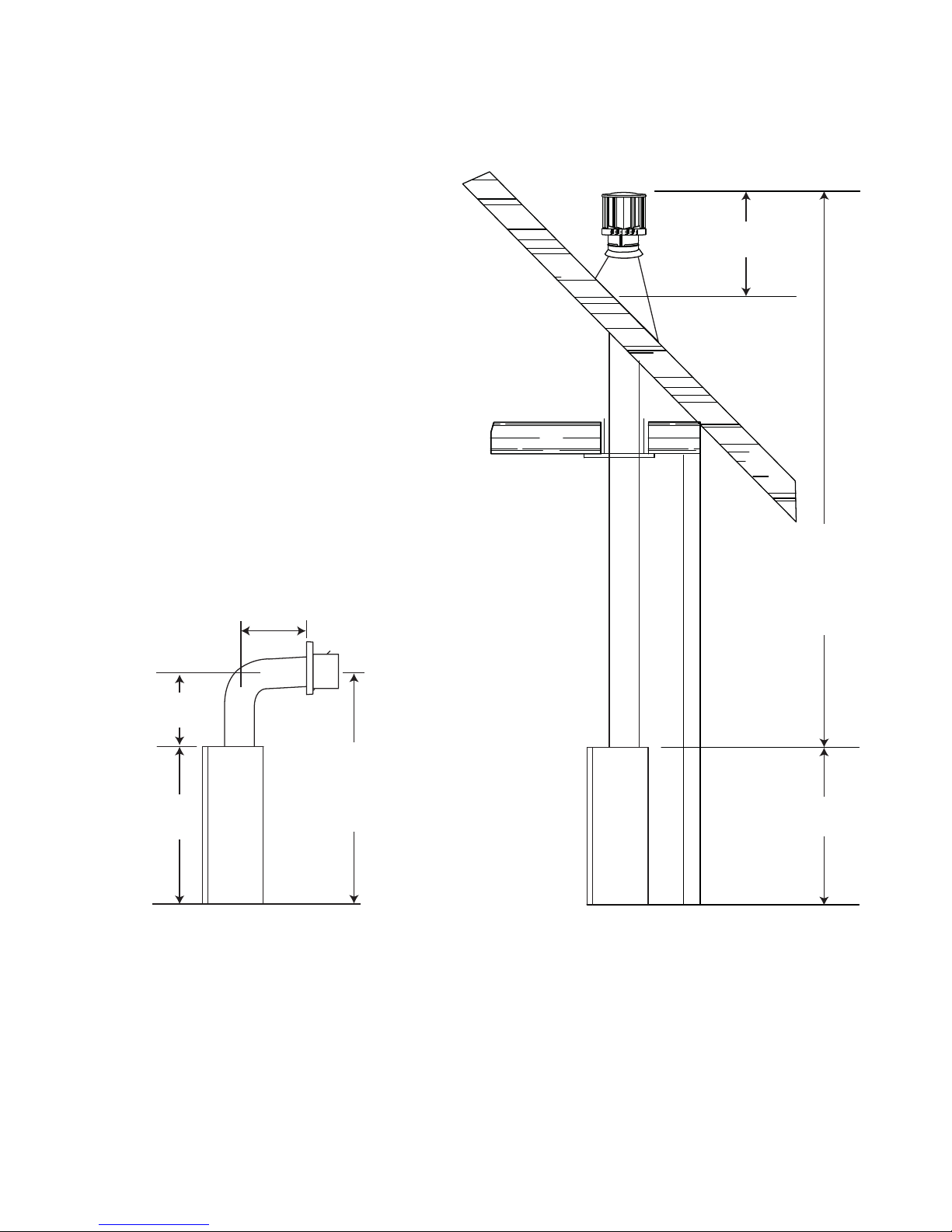
3.2 TYPICAL VENT INSTALLATIONS
16” MIN
24” MAX
24” MIN
38”
* See “VENTING” section.
62”
MIN
PLUS
RISE*
40FT
MAX
3FT
MIN
38”
W415-0889 / A / 08.11.10
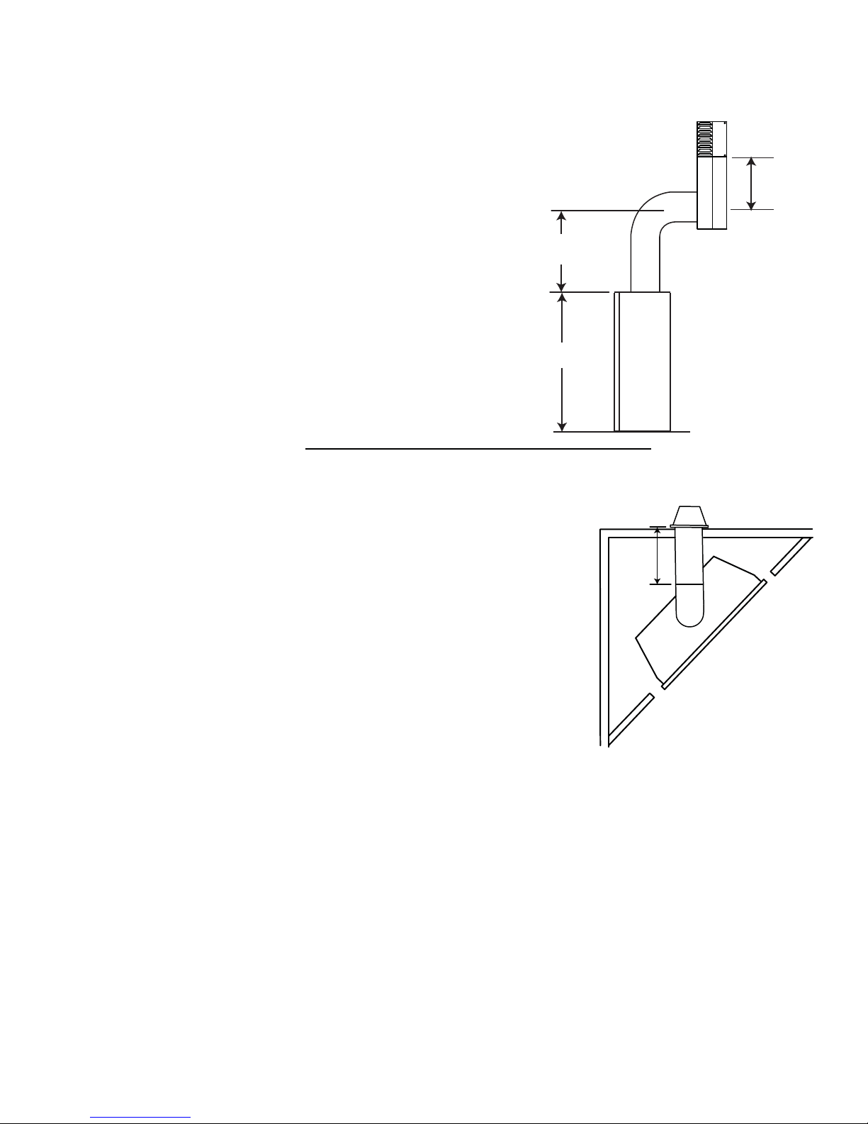
3.3 SPECIAL VENT INSTALLATIONS
3.3.1 PERISCOPE TERMINATION
Use the periscope kit to locate the air termination above grade. The periscope must
be installed so that when fi nal grading is completed, the bottom air slot is located a
minimum 12” above grade. The maximum allowable vent length is 10’.
11
12” MIN TO
GRADE
30” MIN
38”
9.1
3.3.2 CORNER TERMINATION
The maximum vent length for a corner installation is 20” of horizontal run
with a minimum 24” rise.
20”
MAX
W415-0889 / A / 08.11.10
12
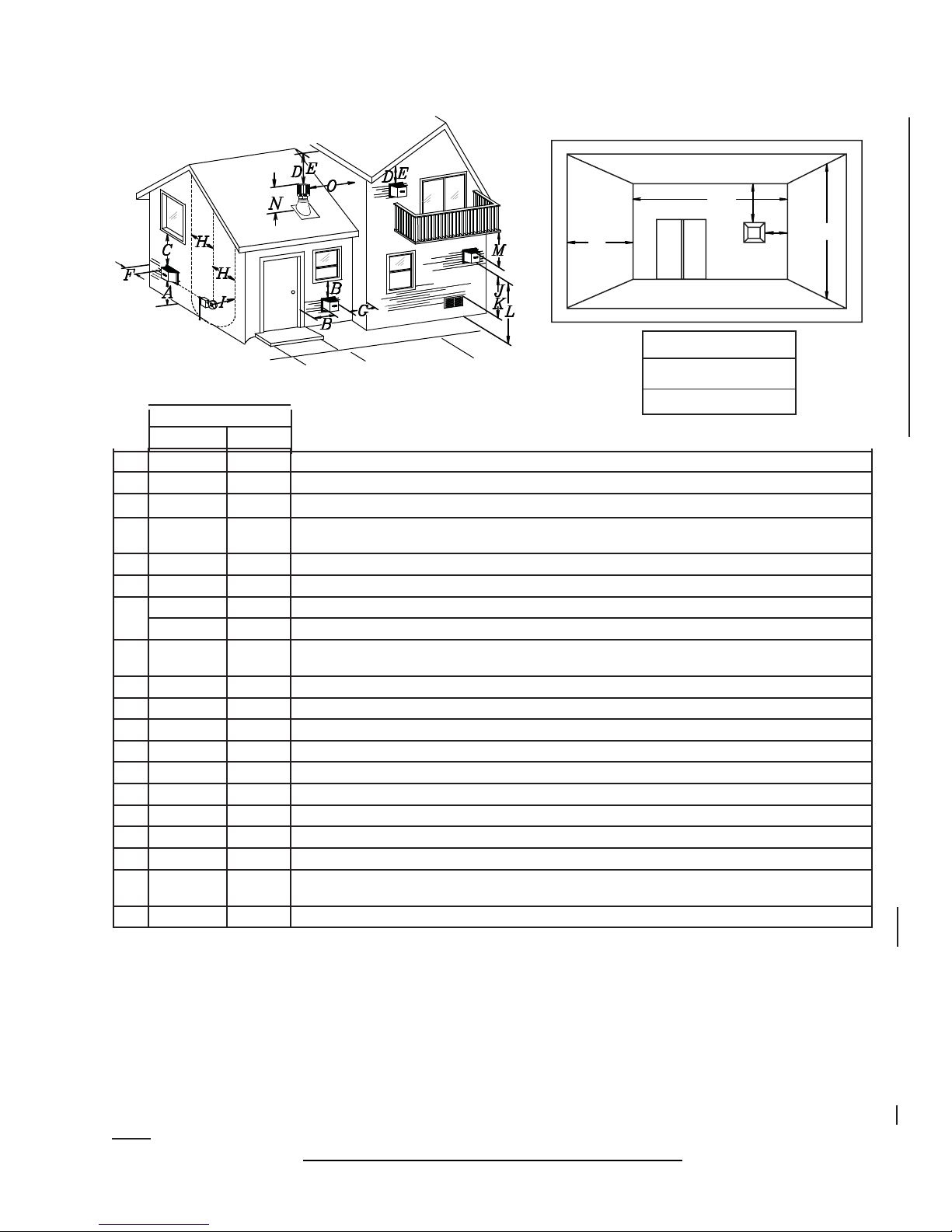
3.4 VENT TERMINAL CLEARANCES
COVERED BALCONY APPLICATIONS ††*
Q
S
R
G
P
Q
R
R
INSTALLATIONS
MIN
MAX
MAX
= 3 feet
= 2 x
Q
feet
ACTUAL
CANADA U.S.A.
A 12” 12” Clearance above grade, veranda porch, deck or balcony.
B 12”
Δ
9”
Δ
Clearance to windows or doors that open.
C 12” * 12” * Clearance to permanently closed windows.
D 18” ** 18” **
Vertical clearance to ventilated soffi ts located above the terminal within a horizontal distance of 2’ from
the centerline of the terminal.
E 12” ** 12” ** Clearance to unventilated soffi t.
F 0” 0” Clearance to an outside corner wall.
G
H 3’ 3’ ****
0” *** 0” *** Clearance to an inside non-combustible corner wall or protruding non-combustible obstructions (chimney, etc.).
2” *** 2” *** Clearance to an inside combustible corner wall or protruding combustible obstructions (vent chase, etc.).
Clearance to each side of the centerline extended above the meter / regulator assembly to a maximum
vertical distance of 15’.
I 3’ 3’ **** Clearance to a service regulator vent outlet.
J 12” 9” Clearance to a non-mechanical air supply inlet to the building or a combustion air inlet to any other appliance.
K 6’ 3’ † Clearance to a mechanical air supply inlet.
L 7’ ‡ 7’ **** Clearance above a paved sidewalk or paved driveway located on public property.
M 12” †† 12” **** Clearance under a veranda, porch or deck.
N 16” 16” Clearance above the roof.
O 2’ †* 2’ †* Clearance from an adjacent wall including neighbouring buildings.
P 8’ 8’ Roof must be non-combustible without openings.
Q 3’ 3’ See chart for wider wall dimensions.
R 6’ 6’
See chart for deeper wall dimensions. The terminal shall not be installed on any wall that has an opening between the terminal and the open side of the structure.
S 12” 12” Clearance under a covered balcony
The terminal shall not be located less than 6 feet under a window that opens on a horizontal plane in a structure with three walls and a roof.
Δ
* Recommended to prevent condensation on windows and thermal breakage
** it is recommended to use a heat shield and to maximize the distance to vinyl clad soffi ts.
*** The periscope requires a minimum 18 inches clearance from an inside corner.
**** This is a recommended distance. For additional requirements check local codes.
† 3 feet above if within 10 feet horizontally.
‡ A vent shall not terminate directly above a sidewalk or paved driveway that is located between two single family dwellings and serves both dwellings.
†† Permitted only if the veranda, porch, or deck is fully open on a minimum of two sides beneath the fl oor.
†* Recommended to prevent recirculation of exhaust products. For additional requirements check local codes.
††* Permitted only if the balcony is fully open on a minimum of one side.
NOTE: Clearances are in accordance with local installation codes and the requirements of the gas supplier.
W415-0889 / A / 08.11.10
12.1B
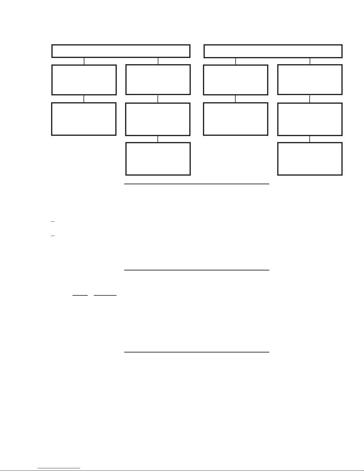
3.5 VENT APPLICATION FLOW CHART
13
Horizontal Termination
Vertical rise is equal
to or greater than
the horizontal run
Horizontal run +
vertical rise to
maximum of 40 feet
3.6 DEFINITIONS
For the following symbols used in the venting calculations and examples are:
> - greater than
> - equal to or greater than
< - less than
< - equal to or less than
HT - total of both horizontal vent lengths (Hr) and offsets (Ho) in feet
HR - combined horizontal vent lengths in feet
HO - offset factor: .03 (total degrees of offset - 90°*) in feet
VT - combined vertical vent lengths in feet
Vertical rise is less
than horizontal run
Horizontal run +
vertical rise to
maximum of 24.75
feet
4.2 times the
vertical rise equal to
or greater than the
horizontal run
Vertical Termination
Vertical rise is equal
to or greater than
the horizontal run
Horizontal run +
vertical rise to
maximum of 40 feet
Vertical rise is less
than horizontal run
Horizontal run +
vertical rise to
maximum of 40 feet
3 times the vertical
rise equal to or
greater than the
horizontal run
13.1
14.1
3.7 ELBOW VENT LENGTH VALUES
FEET INCHES
1° 0.03 0.5
15° 0.45 6.0
30° 0.9 11.0
45° 1.35 16.0
90°* 2.7 32.0
* The fi rst 90° offset has a zero value and is shown in the formula as - 90°
15.1
W415-0889 / A / 08.11.10
14
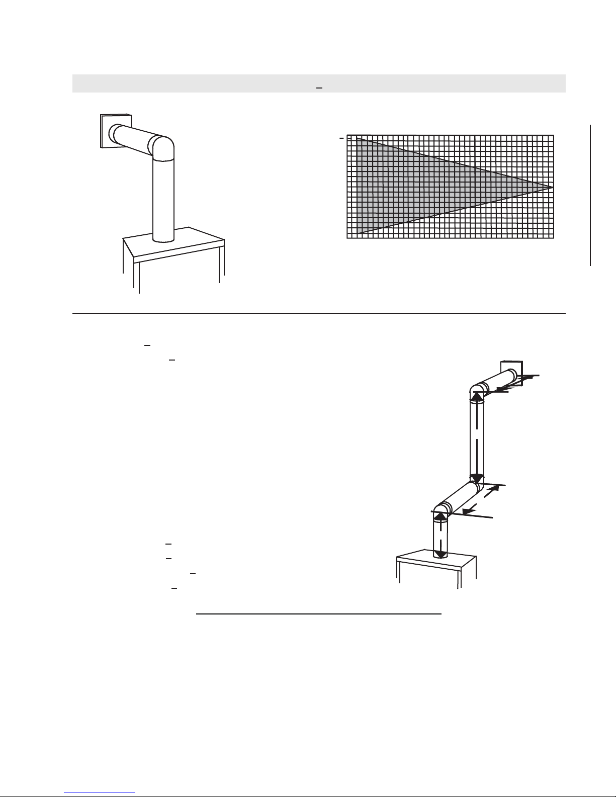
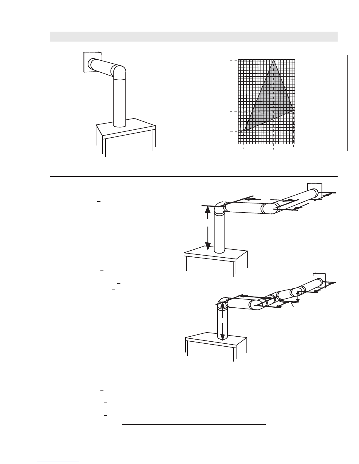
3.8 HORIZONTAL TERMINATION
(HT) < (VT)
Simple venting confi guration (only one 90° elbow)
See graph to determine the required vertical
rise VT for the required horizontal run HT.
40
39
30
REQUIRED
VERTICAL
20
RISE IN
FEET VT
10
0
2.5 5 7.5 10 12.5 15
HORIZONTAL VENT RUN PLUS OFFSET IN
FEET H
T
The shaded area within the lines represents
acceptable values for HT and V
For vent confi gurations requiring more than one 90° elbow, the following formulas apply:
Formula 1: HT < V
T
Formula 2: HT + VT < 40 feet
Example 1:
V
= 3 FT
1
V
= 8 FT
2
VT = V1 + V
H
= 2.5 FT
1
H
= 2 FT
2
HR = H1 + H
H
= .03 (three 90° elbows - 90°) = .03 (270° - 90°) = 5.4 FT
O
= 3 FT + 8 FT = 11 FT
2
= 2.5 + 2 = 4.5 FT
2
HT = HR + HO = 4.5 + 5.4 = 9.9 FT
HT + V
= 9.9 + 11 = 20.9 FT
T
90°
90°
90°
V
2
H
1
17.5 20
T
H
2
Formula 1: HT < V
T
9.9 < 11
Formula 2: HT + VT < 40 FT
20.9 < 40
Since both formulas are met, this vent confi guration is acceptable.
W415-0889 / A / 08.11.10
V
1
16.12
15
V
V
V
V
(HT) > (VT)
Simple venting configuration (only one 90° elbow)
REQUIRED
See graph to determine the required vertical rise VT for the
required horizontal run H
150
147”
100
.
T
VERTICAL
RISE IN
INCHES V
T
57”
50
24”
0
515
2’
10
12.5’
19.5’
20
HORIZONTAL VENT RUN PLUS OFFSET IN FEET H
T
The shaded area within the lines represents acceptable
values for HT and VT
For vent configurations requiring more than one 90° elbow, the following formulas apply:
< 4.2 V
Formula 1:
Formula 2: HT + V
H
T
T
< 24.75 feet
T
90°
H
1
H
2
Example 2:
= VT = 6 FT
1
H
= 3 FT
1
H
= 5 FT
2
H
= H
+ H
R
H
= .03 (two 90° elbows - 90°) = .03 (180° - 90°) = 2.7 FT
O
H
= H
T
H
+ V
T
= 3 + 5 = 8 FT
1
2
+ H
= 8 + 2.7 = 10.7 FT
R
O
= 10.7 + 6 = 16.7 FT
T
V
1
90°
Formula 1: HT < 4.2 V
4.2 VT = 4.2 x 6 = 25.2 FT
10.7 < 25.2
Formula 2: HT + V
16.7 < 24.75
Since both formulas are met, this vent configuration is acceptable.
Example 3:
= 4 FT
1
= 1.5 FT
2
= V
+ V
T
H
= 2 FT
1
H
= 1 FT
2
H
= 1 FT
3
H
= 1.5 FT
4
H
= H
R
H
= .03 (four 90° elbows - 90°) = .03 (360° - 90°) = 8.1 FT
O
H
= H
T
H
+ V
T
= 4 + 1.5 = 5.5 FT
1
2
+ H2 + H
1
+ H
R
= 13.6 + 5.5 = 19.1 FT
T
+ H4 = 2 + 1 + 1 + 1.5 = 5.5 FT
3
= 5.5 + 8.1 = 13.6 FT
O
Formula 1: HT < 4.2 V
4.2 VT = 4.2 x 5.5 = 23.1 FT
T
< 24.75 FT
T
T
90°
90°
90°
H
1
90°
V
1
V
2
H
H
2
3
H
4
13.6 < 23.1
Formula 2: HT + V
19.1 < 24.75
< 24.75 FT
T
Since both formulas are met, this vent configuration is acceptable.
16.13
W415-0889 / A / 08.11.10
16
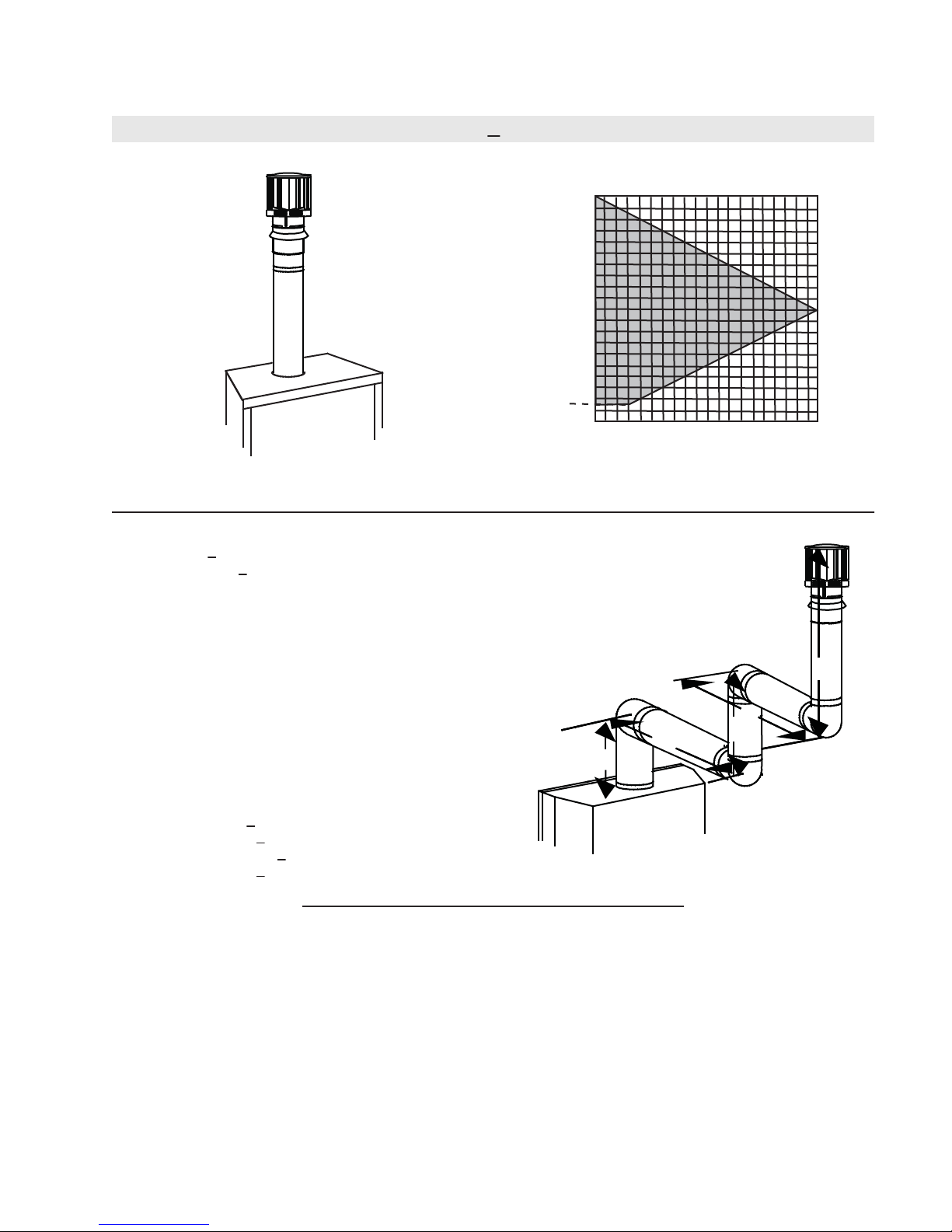
3.9 VERTICAL TERMINATION
(HT) < (VT)
Simple venting configurations.
See graph to determine the required vertical rise V
required horizontal run HT.
40
30
REQUIRED
VERTICAL
20
RISE IN
FEET V
T
10
3
0
5101520
HORIZONTAL VENT RUN PLUS OFFSET IN FEET H
The shaded area within the lines represents acceptable
values for HT and VT
For vent configurations requiring one or more 90° elbows the following formulas apply:
Formula 1: H
Formula 2: HT + V
< V
T
T
< 40 feet
T
for the
T
T
Example 6:
V
= 5 FT
1
V
= 6 FT
2
V
= 10 FT
3
V
= V
+ V2 + V3 = 5 + 6 + 10 = 21 FT
T
1
H
= 8 FT
1
H
= 2.5 FT
2
H
= H
+ H
R
H
= .03 (four 90° elbows - 90°)
O
= .03 (360° - 90°) = 8.1 FT
H
= H
T
H
+ V
T
Formula 1: HT < V
18.6 < 21
Formula 2: HT + V
39.6 < 40
= 8 + 2.5 = 10.5 FT
1
2
+ H
= 10.5 + 8.1 = 18.6 FT
R
O
= 18.6 + 21 = 39.6 FT
T
T
T
< 40 FT
Since both formulas are met, this vent configuration is acceptable.
90°
V
3
90°
H
2
V
H
1
V
1
2
90°
90°
18.1
W415-0889 / A / 08.11.10
 Loading...