

Continental Fireplaces CHD4N, CHD4P Installation And Operating Instructions Manual
INSTALLER: LEAVE THIS MANUAL WITH THE APPLIANCE.
CONSUMER: RETAIN THIS MANUAL FOR FUTURE REFERENCE.
NEVER LEAVE CHILDREN OR OTHER AT RISK INDIVIDUALS ALONE WITH THE APPLIANCE.
EN
INSTALLATION AND
OPERATING INSTRUCTIONS
CERTIFIED UNDER CANADIAN AND AMERICAN NATIONAL STANDARDS: ANSI Z21.50, CSA 2.22 FOR VENTED GAS FIREPLACES.
CHD4N
NATURAL GAS
CHD4P
PROPANE
CERTIFIED FOR CANADA AND UNITED STATES USING ANSI/CSA METHODS.
SAFETY INFORMATION
!
WARNING
If the information in these instructions
are not followed exactly, a fi re or
explosion may result causing property
damage, personal injury or loss of life.
- Do not store or use gasoline or other fl ammable
vapors and liquids in the vicinity of this or any
other appliance.
- WHAT TO DO IF YOU SMELL GAS:
• Do not try to light any appliance.
• Do not touch any electrical switch; do not use
any phone in your building.
• Immediately call your gas supplier from a
neighbour’s phone. Follow the gas supplier’s
instructions.
• If you cannot reach your gas supplier, call the
fi re department.
- Installation and service must be performed by a
qualifi ed installer, service agency or the supplier.
This appliance may be installed in an
aftermarket, permanently located, manufactured
home (USA only) or mobile home, where not
prohibited by local codes.
!
WARNING
HOT GLASS WILL CAUSE
BURNS.
DO NOT TOUCH GLASS UNTIL
COOLED.
NEVER ALLOW CHILDREN TO
TOUCH GLASS.
FR
PG
57
CERTIFIED
This appliance is only for use with the type of
gas indicated on the rating plate. This appliance
is not convertible for use with other gases,
unless a certifi ed kit is used.
Decorative Product: Not for use as a heating appliance.
Wolf Steel Ltd., 24 Napoleon Rd., Barrie, ON, L4M 0G8 Canada /
103 Miller Drive, Crittenden, Kentucky, USA, 41030
Phone (705)721-1212 • Fax (705)722-6031 • www.continentalfi replaces.com • ask@continentalfi re.on.ca
$10.00
1.8C
W415-1150 / 03.07.13

EN
2
TABLE OF CONTENTS
1.0 INSTALLATION OVERVIEW 3
2.0 INTRODUCTION 4
2.1 DIMENSIONS 5
2.1.1 SEE-THRU (CHD4ST AND CHD4STG) 5
2.1.2 PENINSULA (CHD4P AND CHD4PG) 5
2.2 GENERAL INSTRUCTIONS 6
2.3 GENERAL INFORMATION 7
2.4 RATING PLATE / LIGHTING INSTRUCTION LOCATION 8
3.0 VENTING 9
3.1 VENTING LENGTHS AND COMPONENTS 10
3.2 TYPICAL VENT INSTALLATIONS 11
3.3 SPECIAL VENT INSTALLATIONS 12
3.3.1 PERISCOPE TERMINATION 12
3.4 VENT TERMINAL CLEARANCES 13
3.5 VENT APPLICATION FLOW CHART 14
3.6 DEFINITIONS 14
3.7 ELBOW VENT LENGTH VALUES 14
3.8 HORIZONTAL TERMINATION 15
3.9 VERTICAL TERMINATION 17
4.0 INSTALLATION 19
4.1 WALL AND CEILING PROTECTION 19
4.1.1 HORIZONTAL INSTALLATION 20
4.1.2 VERTICAL INSTALLATION 20
4.2 USING FLEXIBLE VENT COMPONENTS 21
4.2.1 HORIZONTAL AIR TERMINAL INSTALLATION 22
4.2.2 VERTICAL AIR TERMINAL INSTALLATION 23
4.2.3 APPLIANCE VENT CONNECTION 23
4.3 GAS INSTALLATION 24
4.4 MOBILE HOME INSTALLATION 24
5.0 FRAMING 25
5.1 FRAMING 26
5.1.1 SEE-THRU FRAMING 26
5.1.2 PENINSULA FRAMING 26
5.2 MINIMUM CLEARANCE TO COMBUSTIBLE ENCLOSURES 27
5.3 INSTALLING CEMENT BOARD 28
5.3.1 FINISHING SUPPORT ADJUSTMENT 29
5.4 NON-COMBUSTIBLE FACING MATERIAL 30
5.5 ALCOVE ENCLOSURE 31
5.6 MINIMUM MANTEL CLEARANCES 32
6.0 FINISHING 33
6.1 DOOR REMOVAL / INSTALLATION 33
6.2 END DOOR REMOVAL / INSTALLATION 34
6.3 LOG PLACEMENT (CHD4ST AND CHD4P ONLY) 35
6.4 GLASS MEDIA INSTALLATION 37
6.5 LOGO PLACEMENT 38
7.0 ELECTRICAL CONNECTION 38
7.1 HARD WIRING CONNECTION 38
7.2 RECEPTACLE WIRING DIAGRAM 39
7.3 BATTERY BACK-UP INSTALLATION 39
7.4 WIRING DIAGRAM 40
8.0 OPERATING INSTRUCTIONS 41
8.1 OPERATING INSTRUCTIONS - FOR YOUR SAFETY READ BEFORE OPERATING 41
8.2 LIGHTING INSTRUCTIONS 41
8.3 ANTI CONDENSATION SWITCH 42
9.0 ADJUSTMENT 43
9.1 PILOT BURNER ADJUSTMENT 43
9.2 VENTURI ADJUSTMENT 43
9.3 FLAME CHARACTERISTICS 44
10.0 MAINTENANCE 45
10.1 ANNUAL MAINTENANCE 45
10.2 GLASS / DOOR REPLACEMENT 46
10.3 CARE OF GLASS 46
10.4 BURNER REMOVAL 47
10.4.1 LOG BURNER REMOVAL (CHD4ST AND CHD4P ONLY) 47
10.4.2 GLASS BURNER REMOVAL (CHD4STG AND CHD4PG ONLY) 47
10.5 VALVE TRAIN REPLACEMENT 48
10.6 RESTRICTING VERTICAL VENTS 48
11.0 REPLACEMENTS 49
12.0 TROUBLESHOOTING 52
13.0 WARRANTY 55
NOTE: Changes, other than editorial, are denoted by a vertical line in the margin.
W415-1150 / 02.28.13
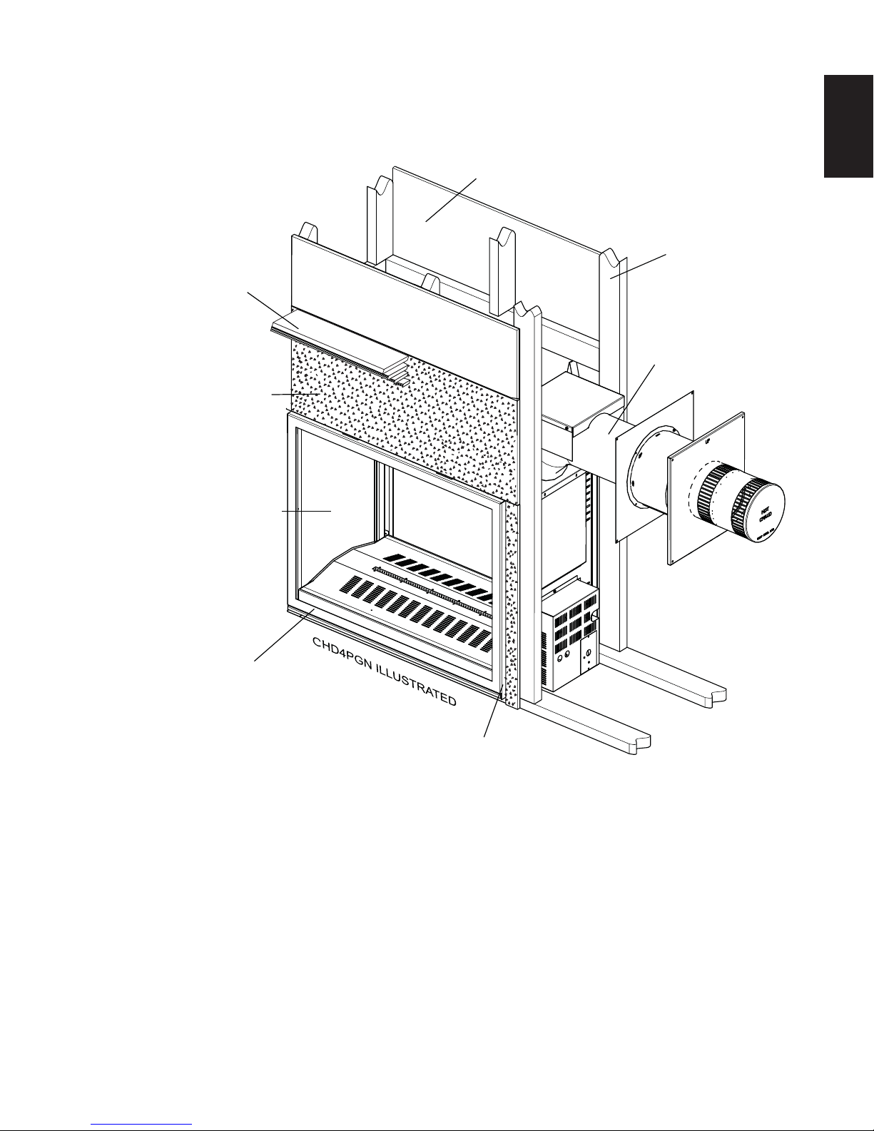
1.0 INSTALLATION OVERVIEW
Mantel, see “MINIMUM
MANTEL CLEARANCES”
section
NON-COMBUSTIBLE
MATERIAL
3
EN
COMBUSTIBLE MATERIAL
Framing, see
“FRAMING” section
Venting, see “VENTING”
section
Door, see “ END DOOR
INSTALLATION” section
Door, see “DOOR REMOVAL/
INSTALLATION” section
Rating plate, see “RATING
PLATE INFORMATION”
section
W415-1150 / 03.07.13

4
2.0 INTRODUCTION
EN
• THIS APPLIANCE IS HOT WHEN OPERATED AND CAN CAUSE SEVERE BURNS IF CONTACTED.
• ANY CHANGES OR ALTERATIONS TO THIS APPLIANCE OR ITS CONTROLS CAN BE DANGEROUS
AND IS PROHIBITED.
• Do not operate appliance before reading and understanding operating instructions. Failure to operate
appliance according to operating instructions could cause fi re or injury.
• Risk of fi re or asphyxiation do not operate appliance with fi xed glass removed.
• Do not connect 110 volts to the control valve.
• Risk of burns. The appliance should be turned off and cooled before servicing.
• Do not install damaged, incomplete or substitute components.
• Risk of cuts and abrasions. Wear protective gloves and safety glasses during installation. Sheet metal edges
may be sharp.
• Do not burn wood or other materials in this appliance.
• Children and adults should be alerted to the hazards of high surface temperature and should stay away to
avoid burns or clothing ignition.
• Young children should be carefully supervised when they are in the same room as the appliance. Toddlers,
young children and others may be susceptible to accidental contact burns. A physical barrier is recommended
if there are at risk individuals in the house. To restrict access to an appliance, install an adjustable safety gate
to keep toddlers, young children and other at risk individuals out of the room and away from hot surfaces.
• Clothing or other fl ammable material should not be placed on or near the appliance.
• Due to high temperatures, the appliance should be located out of traffi c and away from furniture and draperies.
• Ensure you have incorporated adequate safety measure to protect infants/toddlers from touching hot surfaces.
• Even after the appliance is out, the glass and/or screen will remain hot for an extended period of time.
• Check with your local hearth specialty dealer for safety screens and hearth guards to protect children from hot
surfaces. These screens and guards must be fastened to the fl oor.
• Any safety screen or guard removed for servicing must be replaced prior to operating the appliance.
• The appliance is a vented gas-fi red appliance. Do not burn wood or other materials in the appliance
• It is imperative that the control compartments, burners and circulating blower and its passageway in the
appliance and venting system are kept clean. The appliance and its venting system should be inspected
before use and at least annually by a qualifi ed service person. More frequent cleaning may be required due
to excessive lint from carpeting, bedding material, etc. The appliance area must be kept clear and free from
combustible materials, gasoline and other fl ammable vapors and liquids.
• Under no circumstances should this appliance be modifi ed.
• This appliance must not be connected to a chimney fl ue pipe serving a separate solid fuel burning appliance.
• Do not use this appliance if any part has been under water. Immediately call a qualifi ed service technician to
inspect the appliance and to replace any part of the control system and any gas control which has been under
water.
• Do not operate the appliance with the glass door removed, cracked or broken. Replacement of the glass
should be done by a licensed or qualifi ed service person.
• Do not strike or slam shut the appliance glass door.
• When equipped with pressure relief doors, they must be kept closed while the appliance is operating to
prevent exhaust fumes containing carbon monoxide, from entering into the home. Temperatures of the exhaust
escaping through these openings can also cause the surrounding combustible materials to overheat and catch
fi re.
• Only doors / optional fronts certifi ed with the appliance are to be installed on the appliance.
• Keep the packaging material out of reach of children and dispose of the material in a safe manner. As with all
plastic bags, these are not toys and should be kept away from children and infants.
• As with any combustion appliance, we recommend having your appliance regularly inspected and serviced as
well as having a Carbon Monoxide Detector installed in the same area to defend you and your family against
Carbon Monoxide.
• Ensure clearances to combustibles are maintained when building a mantel or shelves above the appliance.
Elevated temperatures on the wall or in the air above the appliance can cause melting, discolouration or
damage of decorations, a T.V. or other electronic components.
!
WARNING
W415-1150 / 02.28.13
3.2B
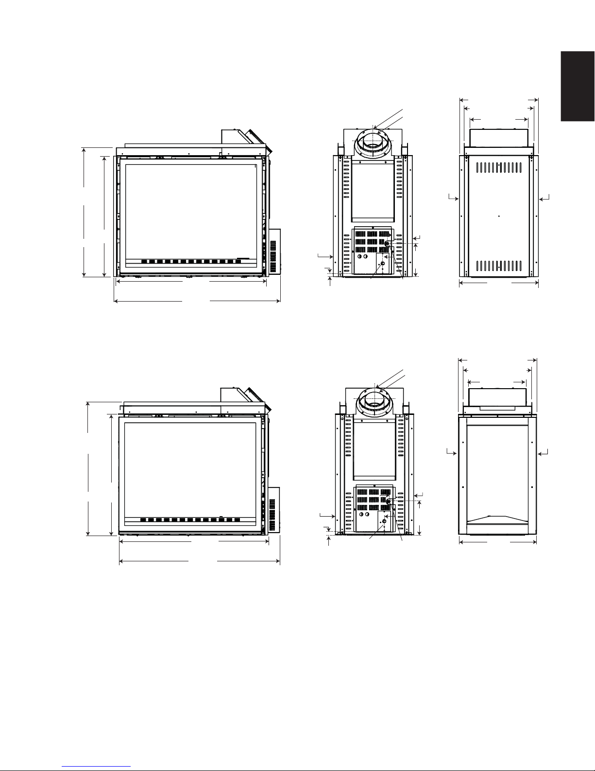
2.1 DIMENSIONS
2.1.1 SEE-THRU (CHD4ST AND CHD4STG)
8” (203.2mm) DIA.
5” (127mm)
DIA.
20 1/8” (511.2mm)
17 5/8” (447.7mm)
14 3/4”
(374.7mm)
5
EN
32 1/4”
(819.2mm)
30 1/4”
(768.4mm)
38 1/4”
(971.6mm)
42 3/8”
(1076.3mm)
CHD4STG ILLUSTRATED
2.1.2 PENINSULA (CHD4P AND CHD4PG)
32 1/4”
(819.2mm)
13 1/4”
(336.6mm)
1 3/4”
(44.5mm)
ELECTRICAL
INLET
6 1/2”
(165.1mm)
8 1/2”
(215.9mm)
GAS INLET
8” (203.2mm) DIA.
5” (127mm)
DIA.
RIGHT
SIDE
RIGHT
SIDE
20 1/8”
(511.2mm)
20 1/8” (511.2mm)
17 5/8” (447.7mm)
14 3/4”
(374.7mm)
LEFT
SIDE
LEFT
SIDE
30 1/4”
(768.4mm)
CHD4STG ILLUSTRATED
36 1/8”
(917.6mm)
41 1/8”
(1044.6mm)
13 1/4”
(336.6mm)
1 3/4”
(44.5mm)
ELECTRICAL
INLET
6 1/2”
(165.1mm)
GAS INLET
8 1/2”
(215.9mm)
20 1/8”
(511.2mm)
W415-1150 / 03.07.13
6
A
A
2.2 GENERAL INSTRUCTIONS
EN
!
WARNING
ALWAYS LIGHT THE PILOT WHETHER FOR THE FIRST TIME OR IF THE GAS SUPPLY HAS RUN OUT,
WITH THE GLASS DOOR OPENED OR REMOVED.
PROVIDE ADEQUATE CLEARANCE FOR SERVICING AND OPERATING THE APPLIANCE.
PROVIDE ADEQUA TE VENTILA TION.
NEVER OBSTRUCT THE FRONT OPENING OF THE APPLIANCE.
OBJECTS PLACED IN FRONT OF THE APPLIANCE MUST BE KEPT A MINIMUM OF 48” (1219.2mm)
FROM THE FRONT FACE OF THE APPLIANCE.
SURFACES AROUND AND ESPECIALLY ABOVE THE APPLIANCE CAN BECOME HOT. AVOID CONTACT
WHEN THE APPLIANCE IS OPERATING.
FIRE RISK. EXPLOSION HAZARD.
HIGH PRESSURE WILL DAMAGE VALVE. DISCONNECT GAS SUPPLY PIPING BEFORE PRESSURE TESTING GAS
LINE AT TEST PRESSURES ABOVE 1/2 PSIG. CLOSE THE MANUAL SHUT-OFF VALVE BEFORE PRESSURE
TESTING GAS LINE AT TEST PRESSURES EQUAL TO OR LESS THAN 1/2 PSIG (35 mb).
USE ONLY WOLF STEEL APPROVED OPTIONAL ACCESSORIES AND REPLACEMENT PARTS WITH THIS APPLIANCE.
USING NON-LISTED ACCESSORIES (BLOWERS, DOORS, LOUVRES, TRIMS, GAS COMPONENTS, VENTING
COMPONENTS, ETC.) COULD RESULT IN A SAFETY HAZARD AND WILL VOID THE WARRANTY AND CERTIFICATION.
THIS GAS APPLIANCE SHOULD BE INSTALLED AND SERVICED BY A QUALIFIED INSTALLER to
conform with local codes. Installation practices vary from region to region and it is important to know the
specifi cs that apply to your area, for example in Massachusetts State:
• This product must be installed by a licensed plumber or gas fi tter when installed within the commonwealth
of Massachusetts.
• The appliance damper must be removed or welded in the open position prior to installation of an appliance
insert or gas log.
• The appliance off valve must be a “T” handle gas cock.
• The fl exible connector must not be longer than 36 inches (914.4mm).
• A Carbon Monoxide detector is required in all rooms containing gas fi red appliances.
• The appliance is not approved for installation in a bedroom or bathroom unless the unit is a direct vent
sealed combustion product.
The installation must conform with local codes or, in
absence of local codes, the National Gas and Propane
Installation Code CSA B149.1 in Canada, or the National
Fuel Gas Code, ANSI Z223.1 / NFPA 54 in the United
States. Suitable for mobile home installation if installed in
accordance with the current standard CAN/CSA Z240MH
Series, for gas equipped mobile homes, in Canada or
NSI Z223.1 and NFPA 54 in the United States.
s long as the required clearance to combustibles is
maintained, the most desirable and benefi cial location
for an appliance is in the center of a building, thereby
allowing the most effi cient use of the heat created. The location of windows, doors and the traffi c fl ow in the
room where the appliance is to be located should be considered. If possible, you should choose a location
where the vent will pass through the house without cutting a fl oor or roof joist.
If the appliance is installed directly on carpeting, vinyl tile or other combustible material other than wood
fl ooring, the appliance shall be installed on a metal or wood panel extending the full width and depth.
Some appliances have optional fans or blowers. If an optional fan or blower is installed, the junction box must
be electrically connected and grounded in accordance with local codes, use the current CSA C22.1 Canadian
Electrical Code in Canada or the ANSI/NFPA 70 National Electrical code in the United States.
www.ncertied.org
We suggest that our gas
hearth products be installed
and serviced by professionals
who are certied in the U.S.
by the National Fireplace
®
Institute
(NFI) as NFI Gas
Specialists
4.1B
W415-1150 / 02.28.13
2.3 GENERAL INFORMATION
7
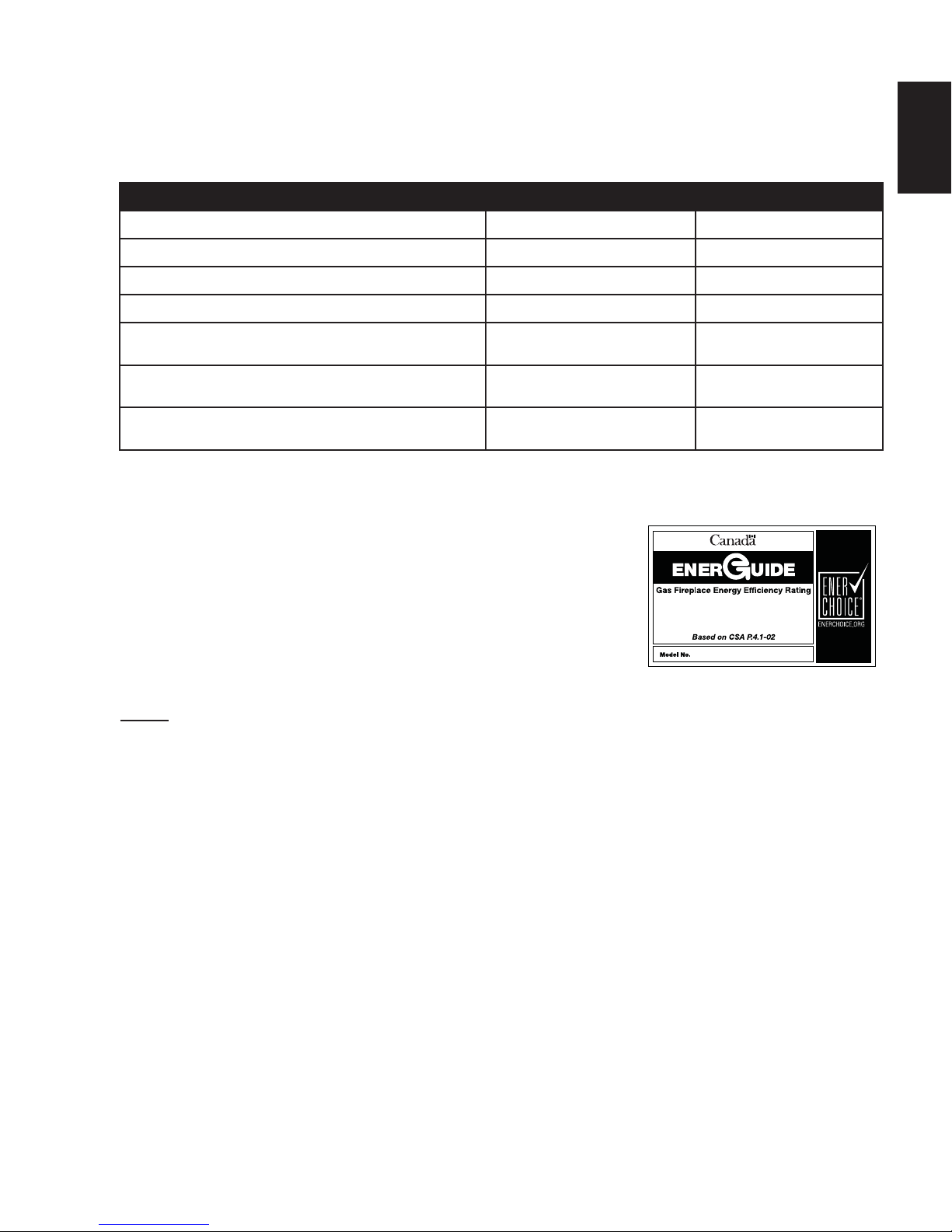
FOR YOUR SATISFACTION, THIS APPLIANCE HAS BEEN TEST-FIRED TO ASSURE ITS OPERATION AND
QUALITY!
NG LP
Altitude (FT) 0-4,500 0-4500
Max. Input (BTU/HR) 30,000 30,000
Max. Output Steady State (BTU/HR) 23,000 23,000
Min. Inlet Gas Supply Pressure
Max. Inlet Gas Supply Pressure
Manifold Pressure (Under Flow Conditions)
When the appliance is installed at elevations above 4,500 ft (1371.6m), and in the absence of specifi c c
recommendations from the local authority having jurisdiction, the certifi ed high altitude input rating shall be
reduced at the rate of 4% for each additional 1,000 ft (304.8m).
This appliance is approved for bathroom, bedroom and bed-sitting room
installations and is suitable for mobile home installation.
4.5" (11.2mb)
Water Column
7" (17.4mb)
Water Column
3.5" (8.7mb)
Water Column
11" (27.4mb)
Water Column
13" (32.4mb)
Water Column
10" (24.9mb)
Water Column
EN
No external electricity (110 volts or 24 volts) is required for the gas system
operation. Expansion / contraction noises during heating up and cooling
down cycles are normal and are to be expected.
If utilizing one of Wolf Steel's trim or surround kits, follow the framing
instructions and the fi nishing instructions, for removal of the top extension.
NOTE: The protective wrap on plated parts is best removed when the assembly is at room temperature
but this can be improved if the assembly is warmed, using a hair dryer or similar heat source.
67.9%
CHD4
W415-1150 / 03.07.13
8
N
R
U
S
E
S
N
É
M
M
R
C
Y
E
L
F
AN
ES, ANSI/NFPA ES, ANSI/NFPA
01A. THIS APPLIANCE MUST BE INSTAL1A. THIS APPLIANCE MUST BE INS
N COMBUSTIBLE SOLIDE NE
6È75e87,/,6e$9(&&(7
5(,/87,/,6(5$9(&/(6
6(8/(0(17$9(&&(77(81,717$9(&&(77(81,
0(17
&(7$33$5(,/$8&810$7e5,$8'($8&810$7e5,$8'
(175(5(1&217$&7$9(&/(6&217$&7$9(&/(6
$875(48(&(/8,48,(67)28(&(/8,48
APPAREIL PAR LE FABRICAEIL PAR LE FABRIC
352'8,7'e&25$7,)1(2'8,7'e&25$7,)1
APPAREIL DE CHAUFFAPPAREIL DE CHAUF
COMBUSTIBCOMBUSTIB
&Ñ7&Ñ'e*$*
266$78
e)e5(5$80$18$/'·,1675
//$7,21'(35235,e7
$7,2135(&,6(,/(67,03257$17'(%,(1$7,2135(&,6(,/(67,03257$17'(%,(1
IN
AL.
FRESH
ERATION
ALLED
VISIONS
R
OM
ARTIMENT DES
TEZ LE MANUEL
N ET
T
ALL
A
TION. ARURE DE SECURITE
AP
AREI
DO
ALIMENTE
W
ARN
G
MPROPER INS
T
ALL
A
TION,
STMEN
T,A
TER
A
TION,
E OR MAINTENAN
ROPERT
Y
DAMAG
Y
OR LOSS OF
OWNER’S
ION
AND
SE
VICE MUST BE PERFORMED
Y
A
QUALIFIED INS
R,
SE
VICE
AGENCY OR TH
GAS SUPPLIER.
A
T
TIO
’ENTR
CAOTWHILE OPEAGASOLINE
2.4 RATING PLATE / LIGHTING INSTRUCTION LOCATION
EN
!
WARNING
ALLOW THE APPLIANCE TO COOL BEFORE PERFORMING ANY MAINTENANCE OR CLEANING.
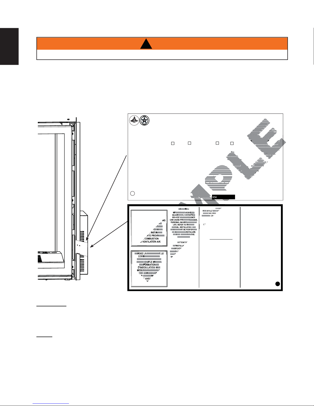
Both the rating plate and lighting instructions are attached to a cable and inserted in a mail slot on the right end
of the appliance (access side). It is recommended to remove the door prior to instruction removal. Using your
fi ngers or a tool such as a screw driver or pencil, gently pull the cable toward you. With the cable at the bulb end
of the slot, wiggle the rating plate out being careful not to tear the instructions as they pass through the slot.
To replace, fold and slide the instructions and the cable back through the slot, as illustrated below, and re-attach
the door (if removed).
&(57,),('81'(5+202/2*8(6(/21/(61250(6$16,=E&6$E9(17('*$6),5(3/$&()2<(5*$=9(17,/e
VENTED GAS FIREPLACE. APPROVED FOR BEDROOM, BATHROOM AND BED-SITTING ROOM INSTALLATION. SUITABLE FOR MOBILE HOME INSTALLATION IF INSTALLED IN ACCORDANCE WITH THE CURRENT
STANDARD CAN/CSA Z240MH SERIES GAS EQUIPPED MOBILE HOMES, IN CANADA OR IN THE UNITED STATES THE MANUFACTURED HOME CONSTRUCTION AND SAFETY STANDARD, TITLE 24 CFR, PART
CERTIFIED
CERTIFIED FOR / CERTIFIEE
POUR CANADA / USA
REFERENCE # 161746
7+,69(17('*$6),5(3/$&(
IS NOT FOR USE WITH AIR
FILTERS.
NOT FOR USE WITH SOLID FUEL.
FOR USE WITH GLASS DOORS
&(57,),(':,7+7+,681,721/<
WARNING: '2127$''$1<0$7(5,$/
TO THE APPLIANCE, WHICH WILL COME IN
CONTACT WITH THE FLAMES, OTHER THAN
7+$76833/,('%<7+(0$18)$&785(5
WITH THE APPLIANCE.
'(&25$7,9(352'8&7127)2586($6$
HEATING APPLIANCE
MINIMUM CLEARANCE TO
COMBUSTIBLE MATERIALS:
TOP 0”
FLOOR 0”
SIDES 0”
BACK 0”
9(17723 µ
9(176,'(6%27720 µ
9(57,&$/9(17 µ
MANTEL 8”*
7236,'(6%$&.3(567$1'2))63$&(56)25)5$0,1*
MATERIALS. FOR FINISHING MATERIALS SEE OWNER’S MANUAL
*MAXIMUM HORIZONTAL EXTENSION / L’EXTENSION HORIZONTALE
MAXIMALE: 2”. SEE INSTRUCTION MANUAL FOR GREATER EXTENSIONS.
SEE OWNER’S INSTRUCTION MANUAL FOR MINIMUM AND MAXIMUM LENGTHS.
3280. WHEN THIS US STANDARD IS NOT APPLICABLE USE THE STANDARD FOR FIRE SAFETY CRITERIA FOR MANUFACTURED HOME INSTALLATIONS, SITES AND COMMUNITIES, ANSI/NFPA 501A. FOYER À
GAZ VENTILÉ. HOMOLOGUÉ POUR INSTALLATION DANS UNE CHAMBRE À COUCHER, UNE SALLE DE BAIN ET UN STUDIO. APPROPRIÉ POUR INSTALLATION DANS UNE MAISON MOBILE SI SON INSTALLATION
CONFORME AUX EXIGENCES DE LA NORME CAN/CSA Z240MH SÉRIE DE MAISONS MOBILES ÉQUIPÉES AU GAZ EN VIGEUR AU CANADA OU AUX ÉTATS-UNIS DE LA NORME DE SECURITE ET DE CONSTRUCTION DE MAISONS MANUFACTUREE, TITRE 24 CFR, SECTION 3280. DANS LE CAS OU CETTE NORME D’ÉTATS-UNIS NE PEUT ETRE APPLIQUÉE, SE REFERER A LA NORME RELATIVE AU CRITÈRE DE
MESURES DE SÉCURITÉ CONTRE L’INCENDIE POUR LES INSTALLATIONS DANS LES MAISONS MANUFACTURÉS, LES SITES ET LES COMMUNAUTÉS, ANSI/NFPA 501A. THIS APPLIANCE MUST BE INSTALLED IN
ACCORDANCE WITH LOCAL CODES, IF ANY; IF NONE, FOLLOW THE CURRENT ANSI Z223.1 OR CSA B149, INSTALLATION CODES. INSTALLER L’APPAREIL SELON LES CODES D’INSTALLATION ANSI Z223.1 OU
CSA-B149 EN VIGUER.
MODEL NATURAL GAS /
GAZ NATURAL
0-4500FT (0-1370M) $/7,78'(e/e9$7,21 0-4500FT (0-1370M)
30,000 BTU/H
%78+ 5('8&(',1387$/,0(17$7,215e'8,7( ,000 BTU/H
3.5” WATER COLUMN/D’UNE COLONNE D’EAU
PRESSION AU COLLECTEUR
4.5“ WATER COLUMN/D’UNE COLONNE D’EAU 0,1,0806833/<35(6685( 11” WATER COLUMN/D’UNE COLONNE D’EAU
7.0“ WATER COLUMN/D’UNE COLONNE D’EAU 0$;,0806833/<35(6685( 13” WATER COLUMN/D’UNE COLONNE D’EAU
67.9% P.4 67.9%
(/(&75,&$/5$7,1*9+=/(667+$1$03(5(6
WOLF STEEL LTD.
24 NAPOLEON ROAD, BARRIE, ON, L4M 0G8 CANADA
HD4N HD4P
7+($33/,$1&(0867%(9(17('86,1*7+($335235,$7(
1$32/(219(17.,766((2:1(56,167$//$7,210$18$/
)259(17,1*63(&,),&63523(55(,167$//$7,21$1'
5(6($/,1*,61(&(66$5<$)7(56(59,&,1*7+(9(17$,5
CHD4N CHD4P
PRESSION D’ALIMENTATION MINIMALE
PRESSION D’ALIMENTATION MAXIMALE
,17$.(6<67(0
SERIAL NUMBER/ NO. DE SÉRIE: HD4
MODEL PROPANE /
PROPANE MODÈLE
INPUT / ALIMENTATION 30,000 BTU/H
MANIFOLD PRESSURE / 10” WATER COLUMN/D’UNE COLONNE D’EAU
/·$33$5(,/'2,7e9$&8(56(6*$=(187,/,6$17
/·(16(0%/('·e9$&8$7,2135235($1$32/(215e)e5(5
$80$18(/'·,167$//$7,21'(35235,e7$,5(3285
/·(9$&8$7,2135(&,6(,/(67,03257$17'(%,(1
5e,167$//(5(75(6&(//(5/·(9(17$35e6$92,5$6685e
/(0$,17,(1'86<67e0('(35,6('·$,5
'(6686&Ñ7e6$55,Ë5(6(/21/(6(63$&(856'(
'e*$*(0(173285/(60$7(5,$8;'·266$785(6(/21
(0(173285/(60$7(5,$8;'·
/$0$18(/'(35235,e7$,5(3285/(60$7e5,$8;'(
$0$18(/'(35235,e7$,5(3285/(60$7e5,$8;'(
FINITION. *L’EXTENSION HORIZONTALE MAXIMALE : 2”.
INITION. *L’EXTENSION HORIZONTALE MAXIMALE : 2”.
)e5(5$80$18$/'·,16758&7,213285'(6
5e)e5(5$80$18$/'·,16758&7,213285'(6
(;7(16,2163/86*5$1'(65e)e5(5$80$18(/
'·,167$//$7,21'(35235,e7$,5(
'·,167$//$7,21'(35235,e7$,5(
&(7)2<(5*$=9(17,/e
1(673$63285/86$*($9(&
1(673$63285/86$*($9(&
LES FILTRES D'AIR.
LES FILTRES D'AIR.
UN COMBUSTIBLE SOLIDE NE
3$6È75e87,/,6e$9(&&(7
$6È75e87,/,6e$9(&&(7
$33$5(,/87,/,6(5$9(&/(6
$33$5(,/87,/,6(5$9(&/(6
3257(9,75e(6+202/2*8e(6
6(8/(0(17$9(&&(77(81,7e
5(6(/21
63e&,),&$7,216e/(&75,48(69
60HZ. MOINS DE 12 AMPÈRES.
N COMBUSTIBLE SOLIDE NE
$'9(57,66(0(17N’AJOUTEZ PAS A
$'9(57,66(0(17
&(7$33$5(,/$8&810$7e5,$8'(9$17
(175(5(1&217$&7$9(&/(6)/$00(6
$875(48(&(/8,48,(67)2851,$9(&7&(7
APPAREIL PAR LE FABRICANT.
352'8,7'e&25$7,)1(3$687,/,6(5&200(
APPAREIL DE CHAUFFAGE
'e*$*(0(1760,1,0$8;'(60$7e5,$8;
COMBUSTIBLES :
DESSUS 0”
PLANCHER 0”
&Ñ7e6 µ
ARRIÈRE 0”
'(6686'8&21'8,7'·(9(17 µ
&Ñ7e6(7'(66286'8&21'8,7
'·(9(17 µ
&21'8,7'·(9(179(57,&$/ µ
TABLETTE 8”*
W385-1899 / B
WARNING:
KEEP BURNER AND CONTROL
COMPARTMENT CLEAN. SEE
INSTALLATION AND OPERA TING
INSTRUCTIONS MANUAL.
APPLIANCE NEEDS FRESH
AIR FOR SAFE OPERATION
AND MUST BE INSTALLED
WITH ADEQUATE PROVISIONS
&6A
G RO
OM INS
2.33 - 2009 VENTED GAS FIREPLACE HE
OR IN
TA
LL
A
THE
TION.
UNITE
E S
SUI
AF
T
D S
ABLE FO
ET
TA
Y
CRI
TE
NE CHAMBR
S
R MOBILE H
TERI
THE MANU
A FOR MANU
A
E À COUCHER,
OME INS
F
Z240M
ACT
URED HOM
F
ACTUR
H SÉRIE DE M
T
A
ALL
TER / CHAUF
CTION
A
E
TION IF INST
U
D
NE SALLE
E
HOME INS
C
3280. D
O
NS
AISON
T
INS
RUCTIO
ANS
DE BA
ALLED IN
T
F
S MOBI
T
A
AGE DE GAZ V
AL
LLA
L
L
E
I
ATIONS DANS
N
N
TIONS, SI
CAS
E
LES ÉQUIP
AND SAFET
ACCO
T
ONE, FO
OU CETT
U
N STU
RDANCE W
TES
ÉES
LLOW
D
Y
LES MAISO
AND
I
ENTILÉ
S
E NOR
O
.
T
AU G
APPRO
ANDARD,
COM
THE CU
ITH
M
AZ EN
E D’É
MUNITIES,
THE
P
NS M
R
RREN
TITLE
IÉ POUR I
VIGEUR
CURREN
T
ATS
ANU
T
-UNIS
2
ANSI
ANSI/
F
4 CFR,
ACTURÉS,
AU CANA
NS
T
Z223.1
NE PEU
NF
T
ALL
P
PA
AR
ATION
501A. FO
T
D
OR CSA
LES
T ETRE
A
OU
S
DANS UNE
IT
AUX É
B149,
ES ET LES COM
YER D
APPLI
T
INS
A
QUÉ
E
TS-U
MAIS
T
MODE
E, SE REFERE
AL
N
L
IS DE
ON
ATION
MUNAUTÉS,
L
A
COD
NO
L
PRO
R
R
ES.
PROP
ME
A
ANSI/NF
L
IN
A
DE
NORME
S
T
CBHD4P
P
ALLER
ANE /
P
ANE MODÈLE
A
UN COMBUSTIBLE SOL
501A
L
’AP
.
THIS
P
AREI
LÉ
VA
L
SELON L
TION
P
AS ÊTRÉ
B
EN
ES
T
DH
A
TION
4
P
0-4500FT (0
UTILISÉ
AP
E
IDE NE
P
N
AREIL. UTILIS
T
A
T
-
I
O
1370
N
30,000 B
A
R
M)
É
VEC CET
PORTE VITRÉES
D
ESSURE /
U
I
T
TU/H
E
2
3
,
0
ER
0
0
LO
B
HOMOLOGUÉES
L
A
T
E
U
C
/
VEC LES
H
T
E
1
U
0”
R
W
P
A
TER COLU
RESSURE /
A
VEC CETTE UNITÉ.
MN/D’UNE COL
N
TA
SEULEMENT
TION
1
M
1” W
INIMALE
ADVERTI
Y
O
A
PRES
NNE D’
T
ER
C
SURE
O
EAU
LUMN/D’
A CET
SSEMENT :
N
T
A
TIO
UNE COLON
AP
N MAXI
PAREI
13”
ENTRER EN CON
E
W
L
A
MAL
T
AU
N’AJOUTEZ
NE D’EAU
ER COLU
E
C
U
N M
AUTRE Q
M
A
TÉRIAU
N
T
PAS
6
/D’U
ACT
7
.
L
9
%
’AP
NE COLONNE
U
A
E CELUI
VEC LES FL
D
CET
P
E
AREI
VANT
AP
QU
L
L
P
DOIT É
’ENSEMBLE D’É
A
I EST
R
D’EAU
A
EI
M
L
M
PAR LE
V
FOURNI
ES
A
AU MANUE
CUER SES
DÉGAGEMENTS MINI
F
A
A
V
VECT
B
ACU
R
ICAN
L
L
GAZ EN
’E
A
D
TION PROPRE
V
’INS
T
ACU
.
COMBUSTIBLE
T
ALL
AT
UTILISANT
RÉINS
ION
A
TION DE PROPRIÉ
MAUX DES MA
PR
A
T
ALLER ET RESCEL
EC
NAPOLEON. RÉFÉRER
I
S :
LE MAINTIEN
SED
SE. I
S
U
S
L
EST IMPOR
TÉRIAU
P
T
AIRE POUR
L
A
DU
N
L
C
X
ER
SYSTÉME DE PRISE D’AIR.
H
T
ANT DE
L
RE
’EVENT
P
R
DESSU
O
B
F
IEN
O
APRÉS
S, C
DN
E
U
C
Ô
A
R
DÉGAGEMENT
Ô
TÉ
VOI
D
E
S &
R
SÉT
L
”0
ASSURÉ
E’
ARRIÈRE : SEL
N
A
LC
A
LA
R
V
R
MANUE
POUR LES M
ÈI
E
F
0
R
A
”
E
C
ON LES ES
E
L
DESSUS DU CONDUIT
DE P
FINITION.
A
2
TERIAU
ROPRIÉT
”0
P
ACEU
*
L
CÔTÉS E
’EXTENSION HORIZ
RÉFÉRER
X
D’OSS
AIRE POUR
RS DE
0
”
T DESSOUS DU CONDU
A
D’EVENT
TURE SELON
AU MAN
D
EX
’
E
L
E
TE
S M
0
NEV
NSIONS
”
UA
T
ON
A
TÉ
L
T
D
AL
CO
RIA
D’INS
’INS
E MAXIMALE : 2”.
PLUS GRAND
NDUIT D
UX DE
TR
3”
T
I
A
UCTION POUR DES
T
LL
’
EV
AT
T
A
ION
ENT VERTICA
B
ES. RÉFÉRER
DE
TEL
T
E
PROPRIÉT
L
SÉRIE: BHD4
2
AU MANUE
”
A
IRE.
L
1”
8
”
*
SPÉCIFIC
ATIONS ÉLECTRI
60HZ. MOINS
DE 12
QUES :
AMPÈRE
1
15
V
,
S.
W385-189
9
FOR COMBUSTION
AND VENTILATION AIR.
GARDEZ LE BRULEUR ET LE
COMPARTIMENT DES
CONTROLES PROPRES.
CONSULTEZ LE MANUEL
D’INFORMATION ET
D’INSTALLATION. PAR
MESURE DE SECURITE.
CET APPAREIL DOIT
ETRE ALIMENTE EN AIR
FRAIS ET AVEC SUFFISANT
D’AIR COMBURANTET
DE VENTILATION.
IMPROPER INSTALLATION,
ADJUSTMENT, ALTERATION,
SERVICE OR MAINTENANCE
CAN CAUSE PROPERTY DAMAGE,
PERSONAL INJURY OR LOSS OF
LIFE. REFER TO OWNER’S
MANUAL. INSTALLATION AND
SERVICE MUST BE PERFORMED
BY A QUALIFIED INSTALLER,
SERVICE AGENCY OR THE
GAS SUPPLIER.
ATTENTION:
UN INSTALLATION OU UNE
MODIFICATION INAPPROPRIEE
DU REGLAGE, DU SERVICE ET DE
L’ENTRETIEN POURRAIENT ETRE
LA CAUSE DE DOMMAGES A LA
PROPRIETE DE BLESSURES
CORPORELLES OU MEME LA
MORT. CONSULTER LE MANUEL
D’INFORMATION, L’INSTALLATION
ET LE SERVICE DOIVENT
ETRE EXECUTES PAR UN
INSTALLATEUR QUALIFIE POUR
LE AZ, UNE ENTREPRISE DE
SERVICE OU LE FOURNISSEUR
DE GAZ SEULEMENT.
CAUTION:
HOT WHILE OPERATING. DO NOT TOUCH.
KEEP CHILDREN, CLOTHING, FURNITURE,
GASOLINE OR OTHER FLAMMABLE VAPORS
AUTRES LIQUIDES QUI EMETTENT DES GAZ
“This appliance is only for use with the type(s)
of gas indicated on the rating plate and may
codes. See owner’s manual for details. This
avec les types de gaz indiqués sur la plaque
mobile installée à demeure si les règlements
l’utilisateur pour plus de renseignements. Une
AWAY.
AVERTISSEMENT:
L’APPAREIL EST CHAUD PENDANT SON
FONCTIONNEMENT. LES ENFANTS, LES
VETEMENTS, LES MEUBLES, L’ESSENCE ET
VOLATILS INFLAMMABLES DOIVENT
ETRE TENUS ELOIGNES DE L’APPAREIL.
be installed in an aftermarket, permanently
located, manufactured home (USA only) or
mobile home, where not prohibited by local
appliance is supplied with a conversion kit.”
«Cet appareil doit être utilisé uniquement
signalétique et peut être installé dans une
maison préfabriquée (É.-U. seulement) ou
locaux le permettent. Voir la notice de
trousse de conversion est fournie avec cet
appareil.»
FOR YOUR SAFETY:
DO NOT STORE OR USE GASOLINE
OR OTHER FLAMMABLE VAPORS
AND LIQUIDS IN VICINITY OF THIS
OR ANY OTHER APPLIANCE.
CAUTION: DO NOT OPERATE
THE FIREPLACE WITH THE GLASS
REMOVED, CRACKED OR BROKEN.
REPLACEMENT OF THE GLASS
SHOULD BE DONE BY A LICENSED
OR QUALIFIED PERSON.
POUR VOTRE
SECURITE:
NE PAS ENTREPOSER NI UTILISER
D’ESSENCE NI D’AUTRES VAPEURS
OU LIQUIDES INFLAMMABLES
ANS LE VOISINAGE DE CET
APPAREIL OU DE TOUT AUTRE
APPAREIL.
AVERTISSEMENT: NE PAS
UTILISER L’APPAREIL SI LE
PANNEAU FRONTAL EN VERRE
N’EST PAS EN PLACE, EST CRAQUÉ
OU BRISÉ. CONFIEZ LE
REMPLACEMENT DU
PANNEAU À UN
TECHNICIEN
AGRÉÉ.
INSTALLER: It is your responsibility to check off the appropriate box on the rating plate according to
the model, venting and gas type of the appliance.
This illustration is for reference only. Refer to the rating plate on the appliance for accurate information.
NOTE: The rating plate must remain with the appliance at all times. It must not be removed.
W415-1150 / 02.28.13

3.0 VENTING
9
!
WARNING
RISK OF FIRE, MAINTAIN SPECIFIED AIR SPACE CLEARANCES TO VENT PIPE AND APPLIANCE.
IF VENTING IS INCLUDED WITH SPACERS THE VENT SYSTEM MUST BE SUPPORTED EVERY 3FT
(0.9m) FOR BOTH VERTICAL AND HORIZONTAL RUNS. USE SUPPORTS OR EQUIVALENT
NON-COMBUSTIBLE STRAPPING TO MAINTAIN THE REQUIRED CLEARANCE FROM
COMBUSTIBLES. USE WOLF STEEL LTD. SUPPORT RING ASSEMBLY W010-0370 OR EQUIVALENT
NON-COMBUSTIBLE STRAPPING TO MAINTAIN THE MINIMUM CLEARANCE TO COMBUSTIBLES
FOR BOTH VERTICAL AND HORIZONTAL RUNS. SPACERS ARE ATTACHED TO THE INNER PIPE AT
PREDETERMINED INTERVALS TO MAINTAIN AN EVEN AIR GAP TO THE OUTER PIPE. THIS GAP IS
REQUIRED FOR SAFE OPERATION. A SPACER IS REQUIRED AT THE START, MIDDLE AND END OF
EACH ELBOW TO ENSURE THIS GAP IS MAINTAINED. THESE SPACERS MUST NOT BE REMOVED.
THIS APPLIANCE USES A 5” (127mm) EXHAUST / 8” (203.2mm) AIR INTAKE VENT PIPE SYSTEM.
Refer to the section applicable to your installation.
For safe and proper operation of the appliance follow the venting instruction exactly. Deviation from the
minimum vertical vent length can create diffi culty in burner start-up and/or carboning. Under extreme vent
confi gurations, allow several minutes (5-15) for the fl ame to stabilize after ignition. Provide a means for
visually checking the vent connection to the appliance after the appliance is installed. Use a fi restop, vent pipe
shield or attic insulation shield when penetrating interior walls, fl oor or ceiling.
NOTE: If for any reason the vent air intake system is disassembled; reinstall per the instructions
provided for the initial installation.
NOTE: This appliance must be installed with a continuous connection of exhaust and air intake vent
pipes. Utilizing alternate constructions such as a chimney as part of the vent system is not permitted.
7.2C
EN
W415-1150 / 03.07.13
10
3.1 VENTING LENGTHS AND COMPONENTS
EN
Use only Wolf Steel, Simpson Dura-Vent, Selkirk Direct Temp, American Metal Amerivent or Metal-Fab
venting components. Minimum and maximum vent lengths, for both horizontal and vertical installations,
and air terminal locations for either system are set out in this manual and must be adhered to. For Simpson
Dura-Vent, Selkirk Direct Temp, American Metal Amerivent and Metal-Fab follow the installation procedure
provided with the venting components.
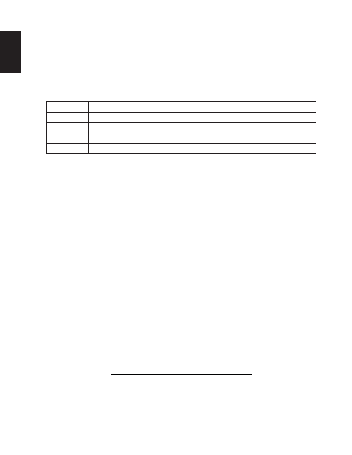
A starter adaptor must be used with the following vent systems and may be purchased from the
corresponding supplier:
PART 5”/8” SUPPLIER WEBSITE
Duravent W175-0170 Wolf Steel www.duravent.com
Amerivent 5DSC-N2 American Metal www.americanmetalproducts.com
Direct Temp 5DT-AA Selkirk www.selkirkcorp.com
SuperSeal 5DDA Metal-Fab www.mtlfab.com
For Simpson Dura-Vent, Selkirk Direct Temp, American Metal Amerivent and Metal-Fab follow the installation
procedure found on the website for your venting supplier.
For vent systems that provide seals on the inner exhaust fl ue, only the outer air intake joints must be sealed using a
red high temperature silicone (RTV). This same sealant may be used on both the inner exhaust and outer intake vent
pipe joints of all other approved vent systems except for the exhaust vent pipe connection to the appliance fl ue collar
which must be sealed using the black high temperature sealant Mill Pac.
When using Wolf Steel venting components, use only approved Wolf Steel rigid / fl exible components with the following
termination kits: wall terminal kit GD422-1, GD422R-1, or 1/12 to 7/12 pitch roof terminal kit GD410, 8/12 to 12/12 roof
terminal kit GD411, fl at roof terminal kit GD412 or periscope kit GD401 (for wall penetration below grade). With fl exible
venting, in conjunction with the various terminations, use either the 5 foot (1.5m) vent kit GD420 or the 10 foot (3.1m)
vent kit GD430.
For optimum fl ame appearance and appliance performance, keep the vent length and number of elbows to a
minimum.
The air terminal must remain unobstructed at all times. Examine the air terminal at least once a year to verify
that it is unobstructed and undamaged.
Rigid and fl exible venting systems must not be combined. Different venting manufacturer components must
not be combined.
These vent kits allow for either horizontal or vertical venting of the appliance. The maximum allowable horizontal
run is 20 feet (6.1m). The maximum allowable vertical vent length is 40 feet (12.2m). The maximum number of vent
connections is two horizontally or three vertically (excluding the appliance and the air terminal connections) when
using fl exible venting.
Horizontal runs may have a 0” (0mm) rise per foot/meter however for optimum performance it is recommended
that all horizontal runs have a minimum 1/4” (6.4mm) rise per foot/meter using fl exible venting. For safe and proper
operation of the appliance, follow the venting instructions exactly.
A terminal shall not terminate directly above a sidewalk or paved driveway which is located between two single family
dwellings and serves both dwellings. Local codes or regulations may require different clearances.
Do not allow the inside liner to bunch up on horizontal or vertical runs and elbows. Keep it pulled tight. A 1¼”
(31.8mm) air gap all around between the inner liner and outer liner is required for safe operation.
8.3A
W415-1150 / 02.28.13
3.2 TYPICAL VENT INSTALLATIONS
11
EN
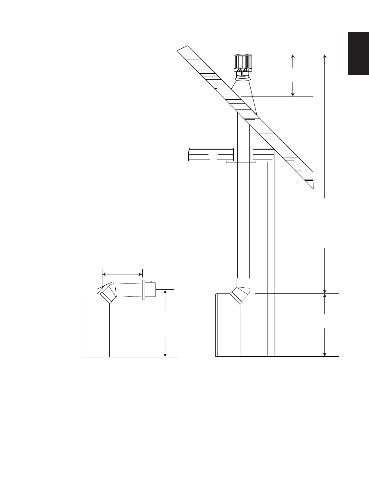
16" MIN
(406.4mm)
24" (609.6mm)
MAX
39" (990.6mm)
MIN PLUS
RISE*
When venting, the horizontal run must be kept to
a maximum of 20 feet (6.1m). If a 20 foot (6.1m)
horizontal run is required, the appliance must
have a minimum vertical rise immediately off the
appliance of 57" (1447.8mm).
On all horizontal vent runs, ensure that the vent pipe does not slope downward.
40 FT
(12.2m)
MAX
36"
(914.4mm)
MIN
39" (990.6mm)
When terminating vertically, the vertical rise is a
minimum 36"(914.4mm) and a maximum 40 feet
(12.2m) above the appliance.
* See "VENTING" section.
W415-1150 / 03.07.13
12
3.3 SPECIAL VENT INSTALLATIONS
3.3.1 PERISCOPE TERMINATION
EN
Use the periscope kit to locate the air termination above grade. The periscope must
be installed so that when fi nal grading is completed, the bottom air slot is located a
minimum of 12” (304.8mm) above grade. The maximum allowable vent length
is 10’ (3.1m) for a fi replace and 8’ (2.4m) for a stove.
12"
(304.80mm)
MIN TO
GRADE
24" (609.60mm) MIN
REGARDLESS OF
HORIZONTAL VENT LENGTH
30 1/4"
(768.35mm)
MIN
9.5B
W415-1150 / 02.28.13
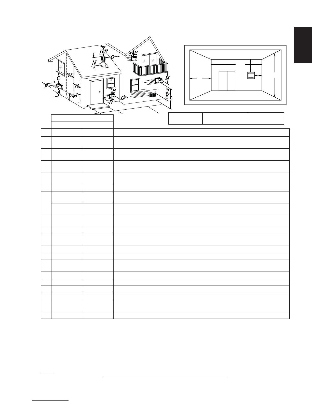
3.4 VENT TERMINAL CLEARANCES
13
COVERED BALCONY APPLICATIONS ††*
Q
R
Q
= 3 feet
INSTALLATIONS
CANADA U.S.A.
A 12” (304.8mm) 12” (304.8mm) Clearance above grade, veranda porch, deck or balcony.
B
C
D
E
F 0” (0mm) 0” (0mm) Clearance to an outside corner wall.
G
H 3’ (0.9m) 3’ (0.9m)****
I 3’ (0.9m) 3’ (0.9m)**** Clearance to a service regulator vent outlet.
J 12” (304.8mm) 9” (228.6mm)
K 6’ (1.8m) 3’ (0.9m) † Clearance to a mechanical air supply inlet.-
L 7’ (2.1m) ‡ 7’ (2.1m) **** Clearance above a paved sidewalk or paved driveway located on public property.
M
N 16” (406.4mm) 16” (406.4mm) Clearance above the roof.
O 2’ (0.6m) †* 2’ (0.6m) †* Clearance from an adjacent wall including neighbouring buildings.
P 8’ (2.4m) 8’ (2.4m) Roof must be non-combustible without openings.
Q 3’ (0.9m) 3’ (0.9m) See chart for wider wall dimensions.
R 6’ (1.8m) 6’ (1.8m)
S 12” (304.8mm) 12” (304.8mm) Clearance under a covered balcony
Δ
* Recommended to prevent condensation on windows and thermal breakage
** It is recommended to use a heat shield and to maximize the distance to vinyl clad soffi ts.
*** The periscope requires a minimum 18 inches (457.2mm) clearance from an inside corner.
**** This is a recommended distance. For additional requirements check local codes.
† 3 feet (0.9m) above if within 10 feet (3.1m) horizontally.
‡ A vent shall not terminate where it may cause hazardous frost or ice accumulations on adjacent property surfaces.
†† Permitted only if the veranda, porch, or deck is fully open on a minimum of two sides beneath the fl oor.
†* Recommended to prevent recirculation of exhaust products. For additional requirements check local codes.
††* Permitted only if the balcony is fully open on a minimum of one side.
NOTE: Clearances are in accordance with local installation codes and the requirements of the gas supplier.
12”
(304.8mm)
12”
(304.8mm)*
18”
(457.2mm)**
12”
(304.8mm)**
0” (0mm)*** 0” (0mm)***
2”
(50.8mm)***
12”
(304.8mm)††
The terminal shall not be located less than 6 feet (1.8m) under a window that opens on a horizontal plane in a structure with three walls and a roof.
9” (228.6mm)ΔClearance to windows or doors that open.
Δ
12”
(304.8mm)*
18”
(457.2mm)**
12”
(304.8mm)**
2” (50.8mm)***
12”
(304.8mm)****
Clearance to permanently closed windows.
Vertical clearance to ventilated soffi ts located above the terminal within a horizontal distance of
2’ (0.6m) from the center line of the terminal.
Clearance to unventilated soffi t.
Clearance to an inside non-combustible corner wall or protruding non-combustible obstructions
(chimney, etc.).
Clearance to an inside combustible corner wall or protruding combustible obstructions (vent
chase, etc.).
Clearance to each side of the center line extended above the meter / regulator assembly to a
maximum vertical distance of 15’ (4.6m).
Clearance to a non-mechanical air supply inlet to the building or a combustion air inlet to any other
appliance.
Clearance under a veranda, porch or deck.
See chart for deeper wall dimensions. The terminal shall not be installed on any wall that has
an opening between the terminal and the open side of the structure.
MIN
(0.9m)
R
= 2 x
MAX
Q
ACTUAL
12.1D
S
R
G
MAX
EN
P
IHHW
(4.6m)
W415-1150 / 03.07.13
14
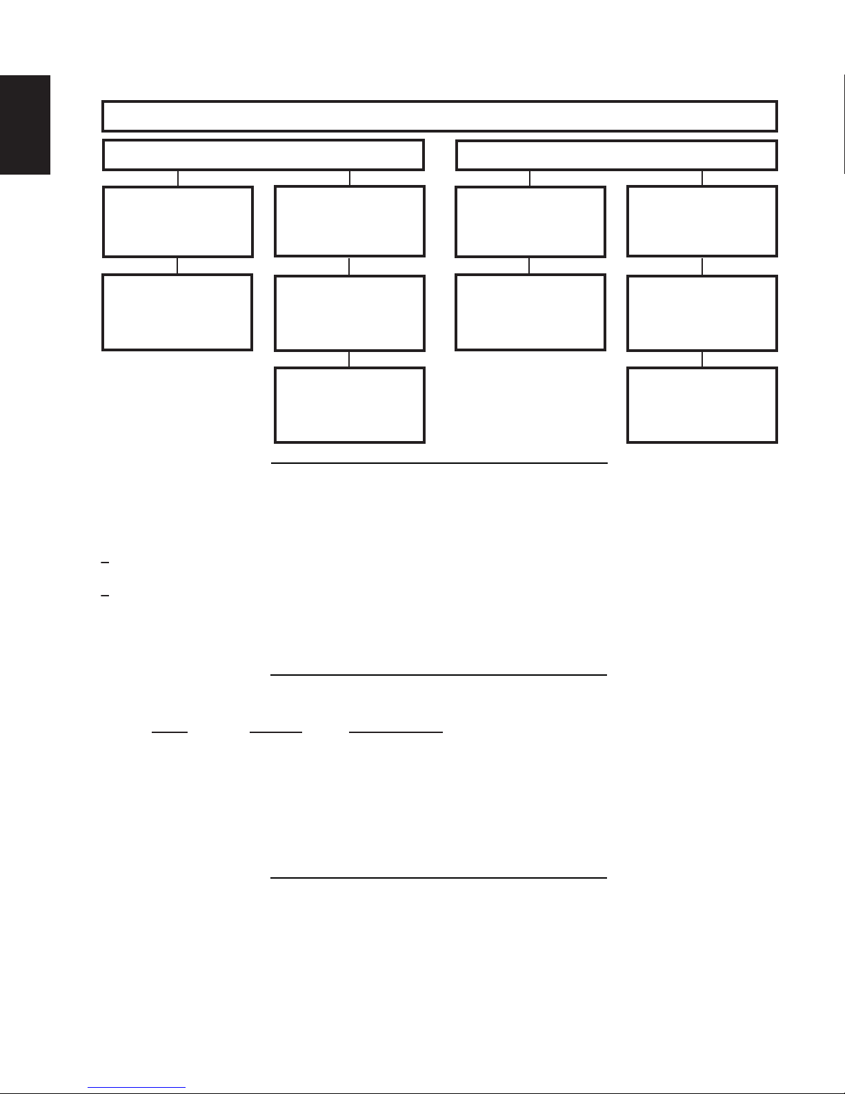
3.5 VENT APPLICATION FLOW CHART
EN
Vertical rise is equal
to or greater than
the horizontal run
Horizontal run +
vertical rise to
maximum of 40 feet
3.6 DEFINITIONS
Horizontal Termination
Vertical rise is less
than horizontal run
Horizontal run +
vertical rise to
(12.2m)
24.75 feet (7.5m)
vertical rise equal to
or greater than the
horizontal run
maximum of
4.2 times the
TOP EXIT
Vertical rise is equal
maximum of 40 feet
Vertical Termination
to or greater than
the horizontal run
Horizontal run +
vertical rise to
(12.2m)
Vertical rise is less
than horizontal run
Horizontal run +
vertical rise to
maximum of 40 feet
(12.2m)
3 times the vertical
rise equal to or
greater than the
horizontal run
13.1A
For the following symbols used in the venting calculations and examples are:
> - greater than
> - equal to or greater than
< - less than
< - equal to or less than
HT - total of both horizontal vent lengths (Hr) and offsets (Ho) in feet
HR - combined horizontal vent lengths in feet
HO - offset factor: .03 (total degrees of offset - 135°*) in feet
VT - combined vertical vent lengths in feet
3.7 ELBOW VENT LENGTH VALUES
FEET INCHES MILLIMETERS
1° 0.03 0.5 12.7
15° 0.45 6.0 152.4
30° 0.9 11.0 279.4
45°* 1.35 16.0 406.4
90°* 2.7 32.0 812.8
* The fi rst 45° and 90°offset has a zero value and is shown in the formula as -45° and - 90° respectively or
-135° when combined.
14.2
15.2A
W415-1150 / 02.28.13
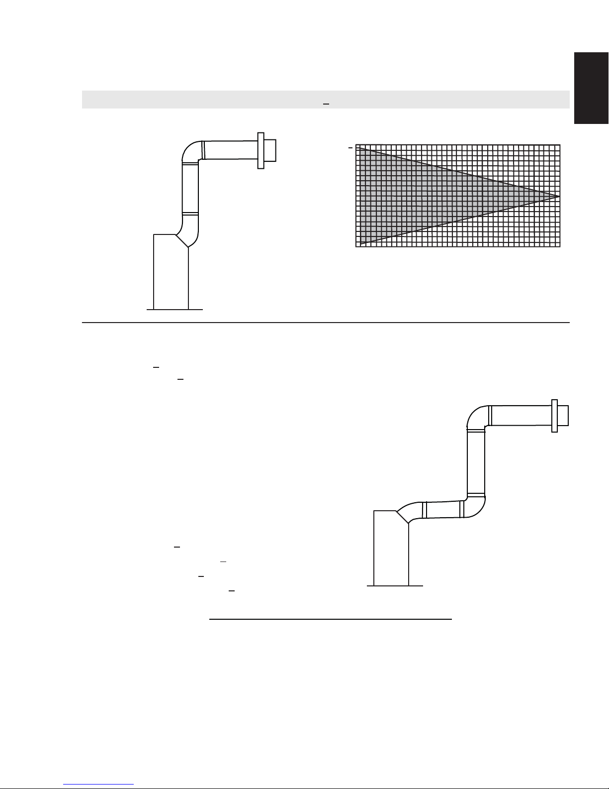
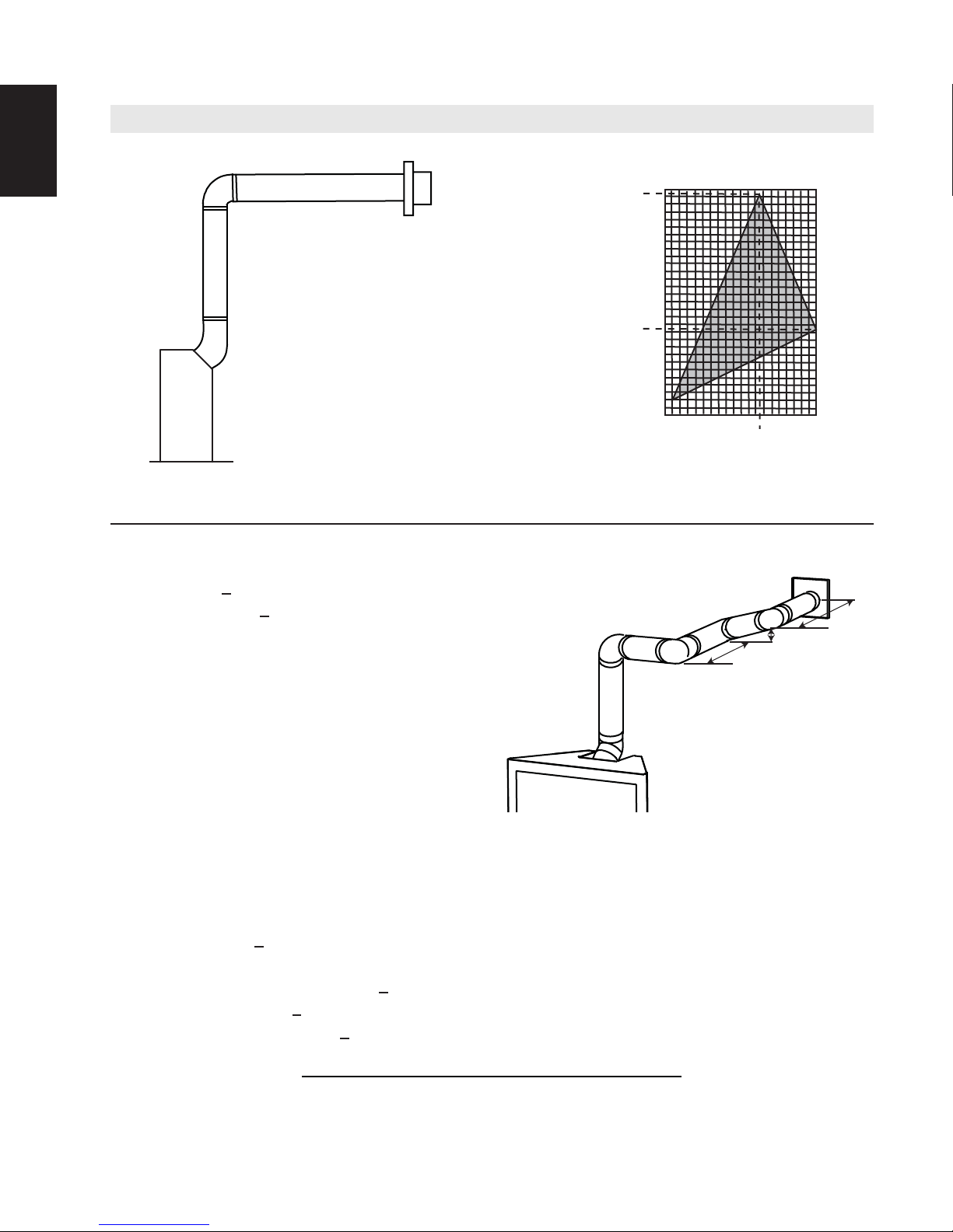
3.8 HORIZONTAL TERMINATION
15
EN
(HT) < (VT)
Simple venting confi guration (only one 45° and 90°
elbow)
REQUIRED
VERTICAL
RISE IN FEET
40 (12.2)
39 (11.9)
30 (9.1)
20 (6.1)
See graph to determine the required vertical
rise VT for the required horizontal run HT.
(METERS) VT
10 (3.1)
0
2.5
(0.8)5 (1.5)
7.5
(2.3)
(3.1)
10
12.5
15
(4.6)
17.5
(5.3)
(3.8)
HORIZONTAL VENT RUN PLUS OFFSET IN
FEET (METERS) H
T
The shaded area within the lines represents
acceptable values for HT and V
T
For vent confi gurations requiring more than one 45° elbow and 90° elbow, the following formulas
apply:
Formula 1: HT < V
T
Formula 2: HT + VT < 40 feet (12.2m)
Example:
V1 = 8 FT (2.4m)
90°
H
2
VT = V1 = 8 FT (2.4m)
H1 = 2.5 FT (0.8m)
H2 = 2 FT (0.6m)
HR = H1 + H2 = 2.5 FT (0.8m) + 2 FT (0.6m) = 4.5 FT (1.4m)
V
1
HO = .03 (one 45° elbow + two 90° elbows - 135°) = .03 (225 - 135°) = 2.7 FT (0.8m)
HT = HR + HO = 4.5 FT (1.4m) + 2.7 FT (0.8m) = 7.2 FT (2.2m)
HT + VT = 7.2 FT (2.2m) + 8 FT (2.4m) = 15.2 FT (4.6m)
45°
H
1
90°
20
(6.1)
Formula 1: HT < V
T
7.2 FT (2.2m) < 8 FT (2.4m)
Formula 2: H
+ VT < 40 FT (12.2m)
T
15.2 FT (4.6m) < 40 FT (12.2m)
Since both formulas are met, this vent confi guration is acceptable.
16.5A
W415-1150 / 03.07.13
EN
16
(HT) > (VT)
Simple venting confi guration (only one 45° and 90°
elbow)
(MILLIMETERS) VT
See graph to determine the required vertical
rise V
REQUIRED
VERTICAL RISE
IN INCHES
for the required horizontal run HT.
T
150 (3810)
147 (3733.8)
100 (2540)
57 (1447.8)
50 (1270)
5
0
(1.5)
10
(3.1)
12.5
(3.8)
15
(4.6)
(6.1)
20
HORIZONTAL VENT RUN PLUS
OFFSET IN FEET (METERS) H
The shaded area within the lines represents acceptable values for HT and V
For vent confi gurations requiring more than one 45° elbow and 90° elbow, the following formulas
apply:
Formula 1: HT < 4.2 V
Formula 2: HT + VT < 24.75 feet (7.5m)
Example:
V1 = 4 FT (1.2m)
V2 = 1.5 FT (0.5m)
VT = V1 + V2= 4 FT (1.2m) + 1.5 FT (0.5m) = 5.5 FT (1.7m)
H1 = 2 FT (0.6m)
H2 = 1 FT (0.3m)
T
90°
H
1
90°
90°
H
3
V
2
H
2
90°
V
1
45°
H3 = 1 FT (0.3m)
H4 = 1.5 FT (0.5m)
HR = H1 + H2 + H3 + H4 = 2FT (0.6m) + 1FT (0.3m) + 1FT (0.3m) + 1.5FT (0.5m) = 5.5 FT (1.7m)
HO = .03 (one 45° elbow + four 90° elbows - 135°) = .03 (405 - 135°) = 8.1 FT (2.5m)
HT = HR + HO = 5.5 FT (1.7m) + 8.1 FT (2.5m) = 13.6 FT (4.2m)
HT + VT = 13.6 FT (4.2m) + 5.5 FT (1.7m) = 19.1 FT (5.8m)
T
H
4
Formula 1: H
< 4.2FT (1.3m) V
T
4.2FT (1.3m) VT = 4.2 FT (1.3m) x 5.5 FT (1.7m)= 23.1 FT (7m)
13.6 FT (4.2m) < 23.1 FT (7M)
Formula 2: H
+ VT < 24.75 FT (7.5m)
T
19.1 FT (5.8m) < 24.75 FT (7.5m)
Since both formulas are met, this vent confi guration is acceptable.
W415-1150 / 02.28.13
T
16.5_2A
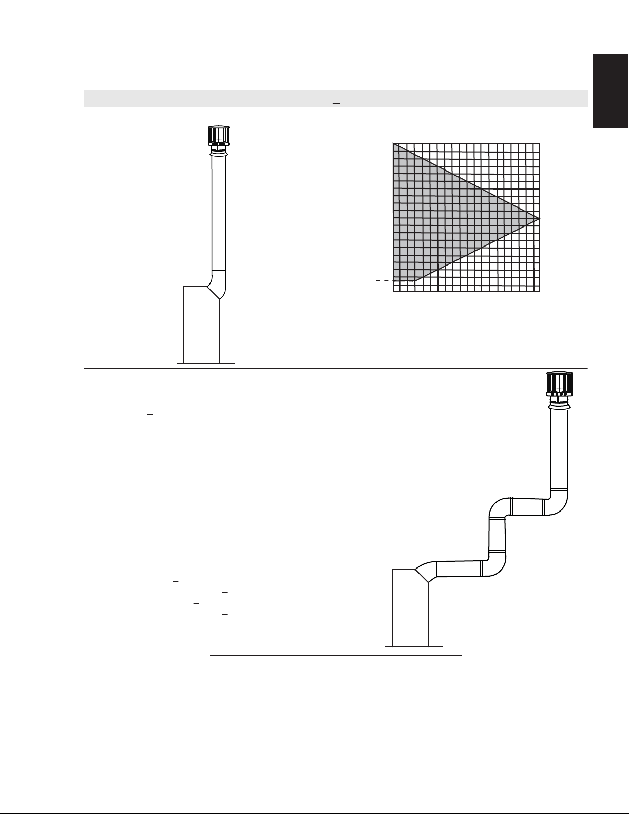
3.9 VERTICAL TERMINATION
17
Simple venting configurations.
(HT) < (VT)
See graph to determine the required vertical rise V
required horizontal run HT.
40 (12.2)
30 (9.1)
REQUIRED
VERTICAL
20 (6.1)
RISE IN FEET
(METERS) V
T
3 (0.9)
10 (3.1)
0
5
(1.5)
10
(3.1)
15
(4.6)
HORIZONTAL VENT RUN PLUS OFFSET IN FEET (METERS) H
The shaded area within the lines represents acceptable
values for H
and VT
T
T
20
(6.1)
for the
EN
T
For vent configurations requiring more than one 45° and one 90° elbow, the following formulas apply:
Formula 1: H
Formula 2: HT + V
< V
T
T
< 40 feet (12.2m)
T
Example:
V
= 5 FT (1.5m)
1
V
= 10 FT (3.1m)
2
V
= V
+ V
T
H
= 3 FT (0.9m)
1
H
= 2.5 FT (0.8m)
2
H
= H
R
H
= .03 (one 45° + three 90° elbows - 135°)
O
= .03 (45 + 270 - 135°) = 5.4 FT (1.6m)
H
= H
T
H
+ V
T
Formula 1: HT < V
10.9FT (3.3m) < 15 (4.6m)
Formula 2: HT + V
25.9FT (7.9m) < 40 (12.2m)
= 5 FT (1.5m) + 10 FT (3.1m) = 15 FT (4.6m)
1
2
+ H
= 3FT (0.9m) + 2.5FT (0.8m) = 5.5 FT (1.7m)
1
2
+ H
= 5.5 FT (1.7m)+ 5.4 FT (1.m) = 10.9 FT (3.3m)
R
O
= 10.9 FT (3.3m)+ 15 FT (4.6m) = 25.9 FT (7.9m)
T
T
< 40 FT (12.2m)
T
45°
90°
H
V
1
H
1
90°
Since both formulas are met, this vent configuration is acceptable.
18.3A
V
2
2
90°
W415-1150 / 03.07.13
18
V
V
V
V
V
V
EN
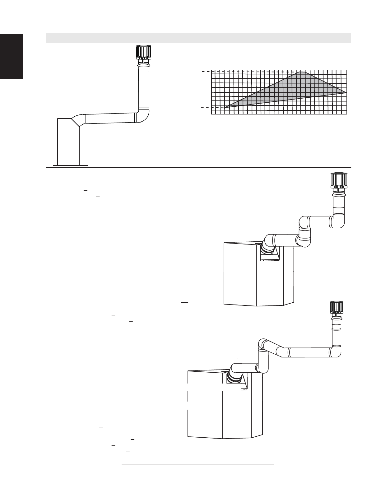
Simple venting configurations.
(HT) > (VT)
20 (6.1)
19 (5.8)
See graph to determine the required vertical rise V
required horizontal run H
.
T
for the
T
REQUIRED
VERTICAL RISE
IN FEET
(METERS) V
10 (3.1)
T
3 (0.9)
0
5
(1.5)
10
(3.1)
15
(4.6)
20
(6.1)
25
(7.6)
(9.1)
HORIZONTAL VENT RUN PLUS OFFSET IN FEET (METERS)H
30
T
The shaded area within the lines represents acceptable
values for H
and VT
T
For vent configurations requiring more than one 45° and one 90° elbow, the following formulas apply:
< 3V
Formula 1:
Formula 2: HT + V
Example:
= 1 FT (0.3m)
1
= 1.5 FT (0.5m)
2
= V
T
H
= 6 FT (1.8m)
1
H
= 2 FT (0.6m)
2
H
= H
R
H
= .03 (one 45° + three 90° elbows - 135°)
O
= .03 (45 + 270 - 135°) = 5.4 FT (1.6m)
H
= H
T
H
+ V
T
H
T
T
< 40 feet (12.2m)
T
+ V
= 1 FT (0.3m)+ 1.5 FT (0.5m)= 2.5 FT (0.8m)
1
2
+ H
= 6FT (1.8m) + 2FT (0.6m) = 8 FT (2.4m)
1
2
+ H
= 8FT (2.4m) + 5.4FT (1.6m) = 13.4FT (4.1m)
R
O
= 13.4FT (4.1m)+ 2.5FT (0.8m) = 15.9FT (4.8m)
T
45°
V
2
90°
H
2
V
H
1
1
90°
90°
Formula 1: H
3VT = 3FT (0.9m) x 2.5FT(0.8m) = 7.5FT (2.3m)
< 3V
T
T
13.4 FT (4.1m) > 7.5 FT (2.3m)
Since this formula is not met, this vent configuration is
Formula 2: HT + V
15.9FT (4.8m) < 40FT (12.2m)
< 40 FT (12.2m)
T
unacceptable.
Since only formula 2 is met, this vent configuration in unacceptable and a new fireplace location or vent
configuration will need to be established to satisfy both formulas.
Example:
= 1.5 FT (0.5m)
1
= 8 FT (2.4m)
2
= V
+ V
T
H
= 1 FT (0.3m)
1
H
= 1 FT (0.3m)
2
H
= 10.75 FT (3.3m)
3
H
= H
R
H
= .03 (three 90° elbows + two 45° elbows - 135°)
O
= .03 (270 + 90 - 135°) = 6.75 FT (2.1m)
H
= H
T
H
+ V
T
Formula 1: H
3VT = 3 x 9.5 = 28.5 FT (8.7m)
= 1.5 FT (0.5m) + 8 FT (2.4m) = 9.5 FT (2.9m)
1
2
+ H2 + H3 = 1FT(0.3m) + 1FT(0.3m) + 10.75FT(3.3m) = 12.75FT(3.9m)
1
+ H
= 12.75 FT (3.9m) + 6.75 FT (2.1m) = 19.5 FT (5.9m)
R
O
= 19.5FT (5.9m) + 9.5FT (2.9m) = 29 FT (8.8m)
T
< 3V
T
T
45°
90°
H
2
V
45°
H
1
1
H
3
V
2
90°
90°
19.5 FT (5.9m) < 28.5 (8.7m)
Formula 2: HT + V
29 FT (8.8m) < 40 FT (12.2m)
< 40 FT (12.2m)
T
Since both formulas are met, this vent configuration is acceptable.
18.3_2B
W415-1150 / 02.28.13
4.0 INSTALLATION
19
!
FOR SAFE AND PROPER OPERATION OF THE APPLIANCE, FOLLOW THE VENTING INSTRUCTIONS
ALL INNER EXHAUST AND OUTER INTAKE VENT PIPE JOINTS MAY BE SEALED USING EITHER RED
RTV HIGH TEMP SILICONE SEALANT W573-0002 (NOT SUPPLIED) OR BLACK HIGH TEMP MILL PAC
W573-0007 (NOT SUPPLIED) WITH THE EXCEPTION OF THE APPLIANCE EXHAUST FLUE COLLAR
WHICH MUST BE SEALED USING MILL PAC.
IF USING PIPE CLAMPS TO CONNECT VENT COMPONENTS, 3 SCREWS MUST ALSO BE USED TO
ENSURE THE CONNECTION CANNOT SLIP OFF.
DO NOT CLAMP THE FLEXIBLE VENT PIPE.
RISK OF FIRE, EXPLOSION OR ASPHYXIATION. IMPROPER SUPPORT OF THE ENTIRE VENTING
SYSTEM MAY ALLOW VENT TO SAG AND SEPARATE. USE VENT RUN SUPPORTS AND CONNECT
VENT SECTIONS PER INSTALLATION INSTRUCTIONS.
RISK OF FIRE, DO NOT ALLOW LOOSE MATERIALS OR INSULATION TO TOUCH THE VENT PIPE.
REMOVE INSULATION TO ALLOW FOR THE INSTALLATION OF THE ATTIC SHIELD AND TO
MAINTAIN CLEARANCES TO COMBUSTIBLES.
4.1 WALL AND CEILING PROTECTION
!
DO NOT FILL THE SPACE BETWEEN THE VENT PIPE AND ENCLOSURE WITH ANY TYPE OF
MATERIAL. DO NOT PACK INSULATION OR COMBUSTIBLES BETWEEN CEILING FIRESTOPS.
ALWAYS MAINTAIN SPECIFIED CLEARANCES AROUND VENTING AND FIRESTOP SYSTEMS.
INSTALL WALL SHIELDS AND FIRESTOPS AS SPECIFIED. FAILURE TO KEEP INSULATION OR
OTHER MATERIALS AWAY FROM VENT PIPE MAY CAUSE FIRE.
WARNING
EXACTLY.
WARNING
EN
68.2A
70.1
For optimum performance it is recommended that all horizontal runs have a minimum of 1/4” (6.35mm) rise
per foot using fl exible venting. For safe and proper operation of the appliance, follow the venting instructions
exactly.
For clearance to combustible materials from the vent pipe, see "MINIMUM CLEARANCE TO
COMBUSTIBLES" section.
NOTE: The fi restop / vent shield supplied with this appliance must be used when passing through a
combustible wall or fl oor.
W415-1150 / 03.07.13
20
A
A
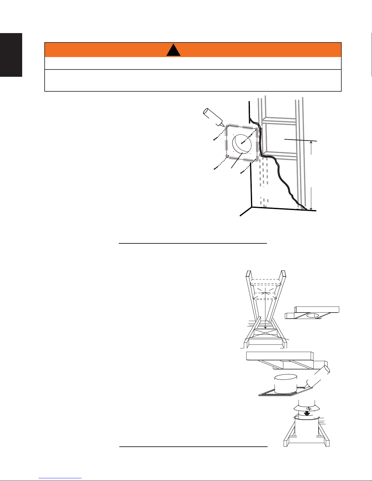
4.1.1 HORIZONTAL INSTALLATION
EN
THE FIRESTOP ASSEMBLY MUST BE INSTALLED WITH THE VENT SHIELD TO THE TOP.
TERMINALS MUST NOT BE RECESSED INTO A WALL OR SIDING MORE THAN THE DEPTH OF THE
This application occurs when venting through an exterior wall.
Having determined the correct height for the air terminal
location, cut and frame a hole in the exterior wall as
illustrated to accommodate the fi restop assembly.
Dry fi t the fi restop assembly before proceeding to
ensure the brackets on the rear surface fi t to the
inside surface of the horizontal framing.
The length of the vent shield may be cut shorter for
combustible walls that are less than 8 1/2” (215.9mm)
thick but the vent shield must extend the full depth of
the combustible wall.
. Apply a bead of caulking (not supplied) around the corner edge of
the inside surface of the fi restop assembly, fi t the fi restop
assembly to the hole and secure using the 4 screws (supplied in your
manual baggie).
!
WARNING
RETURN FLANGE OF THE MOUNTING PLATE.
CAULKING
FIRESTOP
SPACER
VENT
SHIELD
FINISHING
MATERIAL
DETERMINE
THE
CORRECT
HEIGHT
B. Once the vent pipe is installed in its fi nal position, apply high temperature sealant W573-0007 (not
supplied) between the pipe and the fi restop.
20.7A
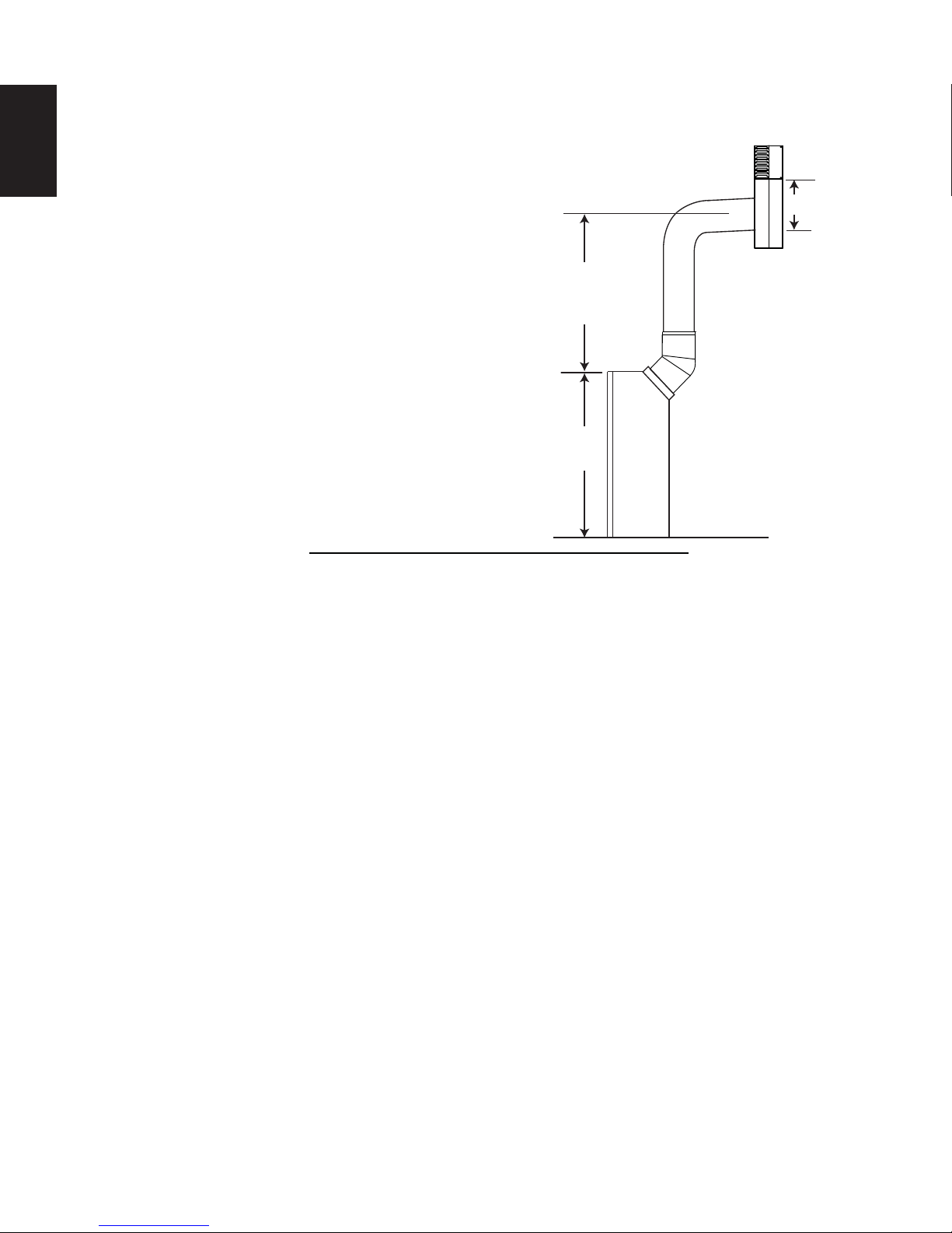
4.1.2 VERTICAL INSTALLATION
This application occurs when venting through a roof. Installation kits for
various roof pitches are available from your authorized dealer / distributor. See
accessories to order specifi c kits required.
. Determine the air terminal location, cut and frame a square opening as
illustrated in the ceiling and the roof to provide the minimum 1” (25.4mm)
clearance between the vent pipe and any combustible material. Try to center
the vent pipe location midway between two joists to prevent having to cut
them. Use a plumb bob to line up the center of the openings. A vent pipe
shield will prevent any materials such as insulation, from fi lling up the
1” (25.4mm) air space around the pipe. Nail headers between the joist for
extra support.
B. Apply a bead of caulking (not supplied) to the framework or to the Wolf
Steel vent pipe shield plate or equivalent (in the case of a fi nished ceiling),
and secure over the opening in the ceiling. A fi restop must be placed on the
bottom of each framed opening in a roof or ceiling that the venting system passes
through. Apply a bead of caulking all around and place a fi restop spacer over
the vent shield to restrict cold air from being drawn into the room or around the
fi replace. Ensure that both spacer and shield maintain the required clearance to
combustibles. Once the vent pipe is installed in its fi nal position, apply sealant
between the pipe and the fi restop assembly.
C. In the attic, slide the vent pipe collar down to cover up the open end of the shield and
tighten. This will prevent any materials, such as insulation, from fi lling up the 1” (25.4mm)
air space around the pipe.
FIRESTOP
UNDERSIDE OF
JOIST
VENT PIPE
SHIELD
SHIELD
21.1A
CAULKING
VENT
PIPE
COLLAR
VENT
PIPE
W415-1150 / 02.28.13
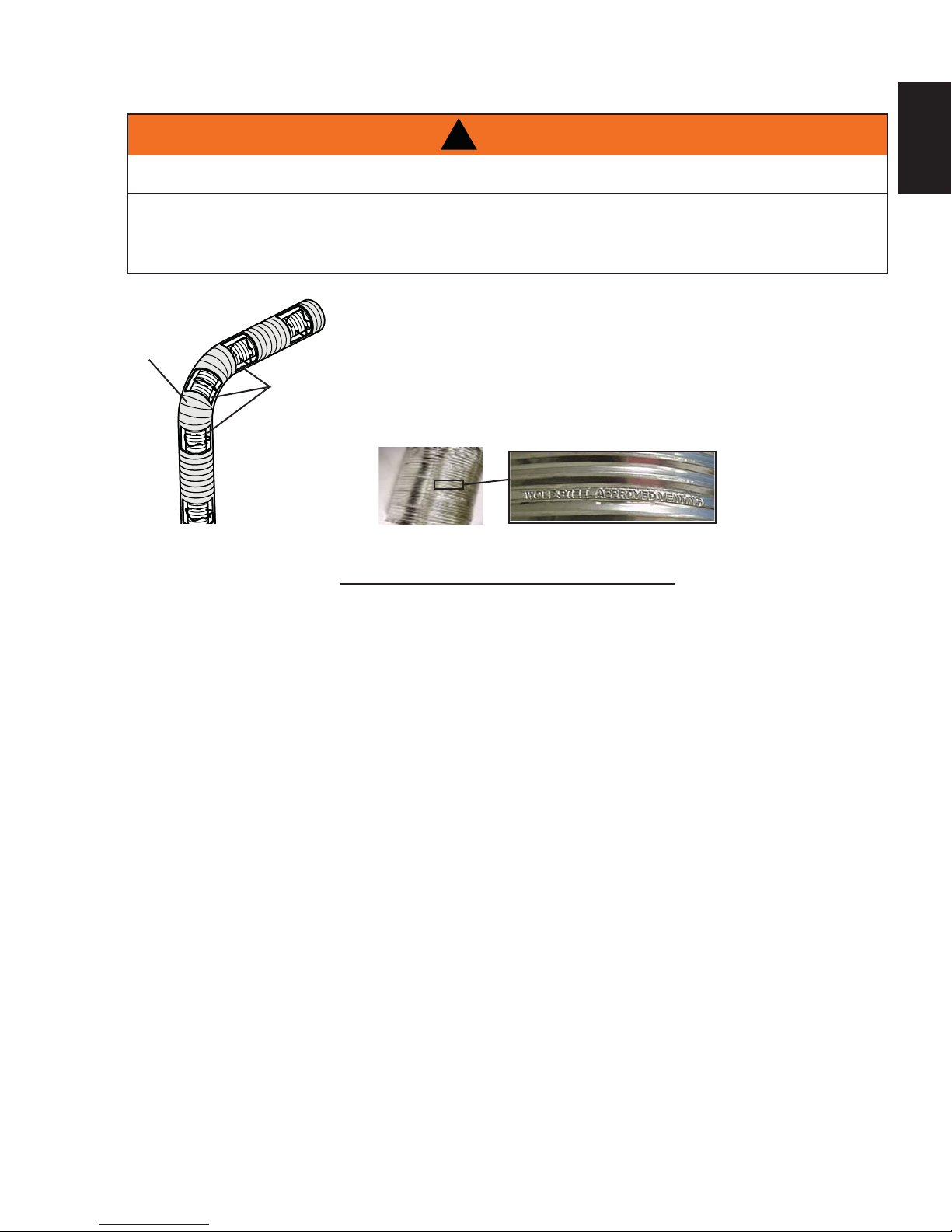
4.2 USING FLEXIBLE VENT COMPONENTS
21
!
WARNING
DO NOT ALLOW THE INNER FLEX PIPE TO BUNCH UP ON HORIZONTAL OR VERTICAL RUNS AND ELBOWS.
KEEP IT PULLED TIGHT.
SPACERS ARE ATTACHED TO THE INNER FLEX PIPE AT PREDETERMINED INTERVALS TO MAINTAIN AN EVEN
AIR GAP TO THE OUTER FLEX PIPE. THIS GAP IS REQUIRED FOR SAFE OPERATION. A SPACER IS REQUIRED
AT THE START, MIDDLE AND END OF EACH ELBOW TO ENSURE THIS GAP IS MAINTAINED. THESE SPACERS
MUST NOT BE REMOVED.
For safe and proper operation of the appliance, follow the venting
instructions exactly.
All inner fl ex pipe and outer fl ex pipe joints may be sealed using high
ELBOW
SPACERS
temperature sealant W573-0002 (not supplied) or the high temperature
sealant W573-0007 Mill Pac (not supplied). However, the high temperature
sealant W573-0007 Mill Pac (not supplied) must be used on the joint
connecting the inner fl ex pipe and the exhaust fl ue collar.
Use only approved fl exible vent pipe kits marked:
“Wolf Steel Approved Venting” as identifi ed
by the stamp only on the outer fl ex pipe.
22.1
EN
W415-1150 / 03.07.13
22
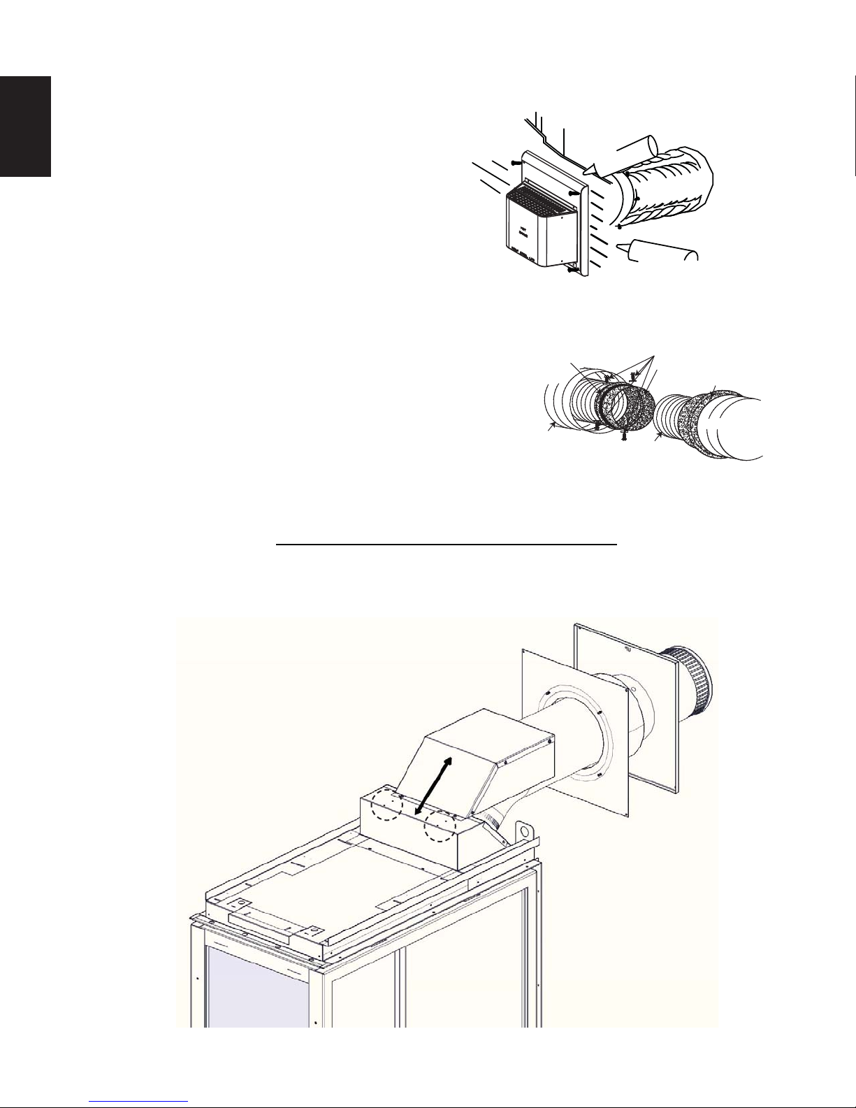
4.2.1 HORIZONTAL AIR TERMINAL INSTALLATION
EN
A. Stretch the inner fl ex pipe to the required length taking into
account the additional length needed for the fi nished wall
surface. Apply a heavy bead of the high temperature
sealant W573-0007 Mill Pac (not supplied) to the inner
sleeve of the air terminal. Slip the vent pipe a minimum
of 2” (50.8mm) over the inner sleeve of the air terminal
and secure with 3 #8 screws.
CAULKING
INNER FLEX
PIPE
2" (50.8mm) OVERLAP
OUTER FLEX PIPE
B. Using the outer fl ex pipe, slide over the outer combustion
air sleeve of the air terminal and secure with 3 #8 screws.
Seal using high temperature sealant W573-0002 (not
#10x2"
SCREWS
HIGH TEMPERATURE
SEALANT
supplied).
C. Insert the vent pipes through the fi restop maintaining the required
clearance to combustibles. Holding the air terminal (lettering in
an upright, readable position), secure to the exterior wall and
make weather tight by sealing with caulking (not supplied).
HI-TEMP
SEALANT
D. If more vent pipe needs to be used to reach the fi replace, couple
them together as illustrated. The vent system must be
supported approximately every 3 feet (0.9m) for both vertical
and horizontal runs. Use noncombustible strapping to
FLEX PIPE
OUTER
#8 X 1/2” SELF DRILLING
SCREWS & WASHERS
INNER COUPLER
OUTER COUPLER
OUTER
FLEX PIPE
INNER
FLEX PIPE
maintain the minimum clearance to combustibles.
The air terminal mounting plate may be recessed into the exterior wall or siding no greater than the depth
of its return fl ange.
23.1B
E. The vent shield must be installed only when terminating horizontally. Remove the two screws nearest
the vent collars on the top of the appliance. Align the vent heat shield (supplied) and secure. Adjust the
vent heat shield to touch the fi restop spacer, as shown below.
W415-1150 / 02.28.13

4.2.2 VERTICAL AIR TERMINAL INSTALLATION
23
!
WARNING
MAINTAIN A MINIMUM 2” (50.8mm) SPACE BETWEEN THE AIR INLET BASE AND THE STORM COLLAR.
A. Fasten the roof support to the roof using the screws provided. The
roof support is optional. In this case the venting is to be adequately
supported using either an alternate method suitable to the authority
having jurisdiction or the optional roof support.
B. Stretch the inner fl ex pipe to the required length. Slip the inner
fl ex pipe a minimum of 2” (50.8mm) over the inner pipe of the
air terminal connector and secure with 3 #8 screws. Seal using
a heavy bead of high temperature sealant W573-0007 (not
supplied).
C. Repeat using the outer fl ex pipe, using a heavy bead of high
temperature sealant W573-0002 (not supplied).
D. Thread the air terminal connector / vent pipe assembly down through
the roof. The air terminal must be positioned vertically and plumb.
ROOF SUPPORT
INNER PIPE
Attach the air terminal connector to the roof support, ensuring that the
top of the air terminal is 16” (406.4mm) above the highest point that it
penetrates the roof.
E. Remove nails from the shingles, above and to the sides of the air
terminal connector. Place the fl ashing over the air terminal connector
leaving a min. 3/4” (19.1mm) of the air terminal connector showing
above the top of the fl ashing. Slide the fl ashing underneath the sides
and upper edge of the shingles. Ensure that the air terminal connector
is properly centred within the fl ashing, giving a 3/4” (19.1mm) margin
all around. Fasten to the roof. Do not nail through the lower portion
AIR
TERMINAL
CONNECTOR
HIGH
TEMPERATURE
SEALANT
INNER FLEX PIPE
OUTER FLEX PIPE
of the fl ashing. Make weather-tight by sealing with caulking. Where
possible, cover the sides and top edges of the fl ashing with roofi ng
material.
F. Aligning the seams of the terminal and air terminal connector,
place the terminal over the air terminal connector making sure the
vent pipe goes into the hole in the terminal. Secure with the three
screws provided.
G. Apply a heavy bead of weatherproof caulking 2” (50.8mm) above
the fl ashing. Install the storm collar around the air terminal and
2”
(50.8mm)
AIR I NL ET
BASE
CAULKING
STORM COLLAR
WEATHER
SEALANT
slide down to the caulking. Tighten to ensure that a weather-tight
seal between the air terminal and the collar is achieved.
H. If more vent pipe needs to be used to reach the appliance see
FLASHING
“HORIZONTAL AIR TERMINAL INSTALLATION” section.
EN
4.2.3 APPLIANCE VENT CONNECTION
A. Install the inner fl ex pipe to the appliance. Secure with 3 screws
and fl at washers. Seal the joint and screw holes using the high
temperature sealant W573-0007 (not supplied).
B. Install the outer fl ex pipe to the appliance. Attach and seal the joints
using the high temperature sealant W573-0002 (not supplied).
#8 X 1/2”
DRILLING
SCREWS
HIGH
TEMPERATURE
SEALANT
24.1A
SELF
HIGH TEMPERATURE
SEALANT
28.2A
W415-1150 / 03.07.13
2” (50.8mm)
OVERLAP
2” (50.8mm)
OVERLAP
#8 X 1/2”
DRILLING
SCREWS
SELF
24
A
4.3 GAS INSTALLATION
EN
!
WARNING
RISK OF FIRE, EXPLOSION OR ASPHYXIATION. ENSURE THERE ARE NO IGNITION SOURCES SUCH AS
SUPPORT GAS CONTROL WHEN ATTACHING GAS SUPPLY PIPE TO PREVENT DAMAGING GAS LINE.
ALWAYS LIGHT THE PILOT WHETHER FOR THE FIRST TIME OR IF THE GAS SUPPLY HAS RUN OUT
WITH THE GLASS DOOR OPENED OR REMOVED. PURGING OF THE GAS SUPPLY LINE SHOULD BE
PERFORMED BY A QUALIFIED SERVICE TECHNICIAN. ASSURE THAT A CONTINUOUS GAS FLOW IS AT
THE BURNER BEFORE CLOSING THE DOOR. ENSURE ADEQUATE VENTILATION. FOR GAS AND
ELECTRICAL LOCATIONS, SEE “DIMENSION” SECTION.
ALL GAS CONNECTIONS MUST BE CONTAINED WITHIN THE APPLIANCE WHEN COMPLETE.
HIGH PRESSURE WILL DAMAGE VALVE. DISCONNECT GAS SUPPLY PIPING BEFORE TESTING GAS
LINE AT TEST PRESSURES ABOVE 1/2 PSIG.
VALVE SETTINGS HAVE BEEN FACTORY SET, DO NOT CHANGE.
Installation and servicing to be done by a qualifi ed installer. Do not use open fl ame.
• Move the appliance into position and secure.
• If equipped with a fl ex connector the appliance is designed to accept a 1/2” gas supply. Without the
connector it is designed to accept a 3/8” gas supply. The appliance is equipped with a manual shut off
valve to turn off the gas supply to the appliance.
• Connect the gas supply in accordance to local codes. In the absence of local codes, install to the
current CAN/CSA-B149.1 Installation Code in Canada or to the current National Fuel Gas Code, ANSI
Z223.1 / NFPA 54 in the United States.
• When fl exing any gas line, support the gas valve so that the lines are not bent or kinked.
• Check for gas leaks by brushing on a soap and water solution.
SPARKS OR OPEN FLAMES.
30.1
4.4 MOBILE HOME INSTALLATION
This appliance is also certifi ed to be installed as an OEM (Original Equipment Manufacturer) installation
in a manufactured home (U.S. only) or mobile home and must be installed in accordance with the
manufacturer’s instructions and the Manufactured Home Construction and Safety Standard, Title 24 CFR,
Part 3280, in the United States or the Mobile Home Standard, CAN/CSA Z240 MH Series, in Canada. This
appliance is only for use with the type(s) of gas indicated on the rating plate.
This Mobile/Manufactured Home Listed appliance comes factory equipped with a means to secure the unit. Built
in appliances are equipped with 1/4” (6.4mm) diameter holes located in the front left and right corners of the
base. Use #10 hex head screws, inserted through the holes in the base to secure. For free standing products
contact your local authorized dealer / distributor for the appropriate securing kit. For mobile home installations, the
appliance must be fastened in place. It is recommended that the appliance be secured in all installations. Always
turn off the pilot and the fuel supply at the source, prior to moving the mobile home. After moving the mobile home
and prior to lighting the appliance, ensure that the logs are positioned correctly.
This appliance is certifi ed to be installed in an aftermarket permanently located, manufactured (mobile)
home, where not prohibited by local codes.
This appliance is only for use with the type of gas indicated on the rating plate. This appliance is not
convertible for use with other gases, unless a certifi ed kit is used.
conversion kit is supplied with the mobile home appliance.
Conversion Kits
This appliance is fi eld convertible between Natural Gas (NG) and Propane (LP).
To convert from one gas to another consult your Authorized dealer/distributor.
29.1A
W415-1150 / 02.28.13
5.0 FRAMING
25
!
WARNING
RISK OF FIRE!
IN ORDER TO AVOID THE POSSIBILITY OF EXPOSED INSULATION OR VAPOUR BARRIER COMING
IN CONTACT WITH THE APPLIANCE BODY, IT IS RECOMMENDED THAT THE WALLS OF THE
APPLIANCE ENCLOSURE BE “FINISHED” (IE: DRYWALL / SHEETROCK), AS YOU WOULD FINISH
ANY OTHER OUTSIDE WALL OF A HOME. THIS WILL ENSURE THAT CLEARANCE TO
COMBUSTIBLES IS MAINTAINED WITHIN THE CAVITY.
DO NOT NOTCH THE FRAMING AROUND THE APPLIANCE STAND-OFFS. FAILURE TO MAINTAIN
AIR SPACE CLEARANCE MAY CAUSE OVER HEATING AND FIRE. PREVENT CONTACT WITH
SAGGING OR LOOSE INSULATION OR FRAMING AND OTHER COMBUSTIBLE MATERIALS. BLOCK
OPENING INTO THE CHASE TO PREVENT ENTRY OF BLOWN-IN INSULATION. MAKE SURE
INSULATION AND OTHER MATERIALS ARE SECURED.
WHEN CONSTRUCTING THE ENCLOSURE ALLOW FOR FINISHING MATERIAL THICKNESS TO
MAINTAIN CLEARANCES. FRAMING OR FINISHING MATERIAL CLOSER THAN THE MINIMUMS
LISTED MUST BE CONSTRUCTED ENTIRELY OF NON-COMBUSTIBLE MATERIALS. MATERIALS
CONSISTING ENTIRELY OF STEEL, IRON, BRICK, TILE, CONCRETE, SLATE, GLASS OR PLASTERS,
OR ANY COMBINATION THEREOF ARE SUITABLE. MATERIALS THAT ARE REPORTED AS PASSING
ASTM E 136, STANDARD TEST METHOD FOR BEHAVIOUR OF MATERIALS IN A VERTICAL TUBE
FURNACE AT 1382° F (750°C) AND UL763 SHALL BE CONSIDERED NON-COMBUSTIBLE
MATERIALS.
MINIMUM CLEARANCE TO COMBUSTIBLES MUST BE MAINTAINED OR A SERIOUS FIRE HAZARD
COULD RESULT.
THE APPLIANCE REQUIRES A MINIMUM ENCLOSURE HEIGHT. MEASURE FROM THE APPLIANCE
BASE.
IF STEEL STUD FRAMING KITS WITH CEMENT BOARD ARE PROVIDED, OR SPECIFIED IN THE
INSTALLATION INSTRUCTIONS. THEY MUST BE INSTALLED.
FINISHING MUST BE DONE USING A NON-COMBUSTIBLE MATERIAL PLACED FLUSH WITH THE
FRONT FACE OF THE UNIT AND EXTENDING FROM THE TOP OF THE UNIT SUCH AS
CEMENT BOARD, CERAMIC TILE, MARBLE, ETC. DO NOT USE WOOD OR DRYWALL.
ANY FIRE RATED DRYWALL IS NOT ACCEPTABLE.
71.1B
It is best to frame your appliance after it is positioned and the vent system is installed.
When roughing in the appliance, raise the appliance to accommodate for the thickness of the fi nished fl oor
materials, i.e. tile, carpeting and hard wood.
EN
Maintain these minimum clearances to combustibles from appliance and vent surfaces:
Appliance framing:
Non- Combustible Appliance fi nishing:
Front - 2” (50.8mm) to sides of appliance opening
- 15 3/4” (400.1mm) above appliance opening
Combustible Appliance fi nishing:
- 46” (1168.4mm) from bottom of appliance to enclosure top
- 3” (76.2mm) to top of vent pipe*
- 2” (50.8mm) to sides and bottom of vent pipe*
Non-combustible fi nishing material (ie. cement board, brick, stone, tile) must be used to fi nish around the
front of the appliance.
*HORIZONTAL VENT SECTIONS: A minimum clearance of 3” (76.2mm) to the top and 2” (50.8mm) to the
sides and bottom of the vent pipe on all horizontal runs to combustibles is required. Horizontal vent sections
within enclosures require a minimum clearance of 3” (76.2mm) at the top of the vent pipe, see “MINIMUM
CLEARANCE TO COMBUSTIBLE ENCLOSURES” section. Use fi restop assembly W010-2985.
*VERTICAL VENT SECTIONS: A minimum of 1” (25.4mm) all around the vent pipe on all vertical runs to
combustibles is required except for clearances in appliance enclosures. Vertical vent sections within enclosures
require a minimum clearance of 2” (50.8mm) around the vent pipe. Use fi restop spacer W010-2985.
W415-1150 / 03.07.13
26
* When constructing the enclosure allow for fi nishing material thickness to maintain clearances.
EN
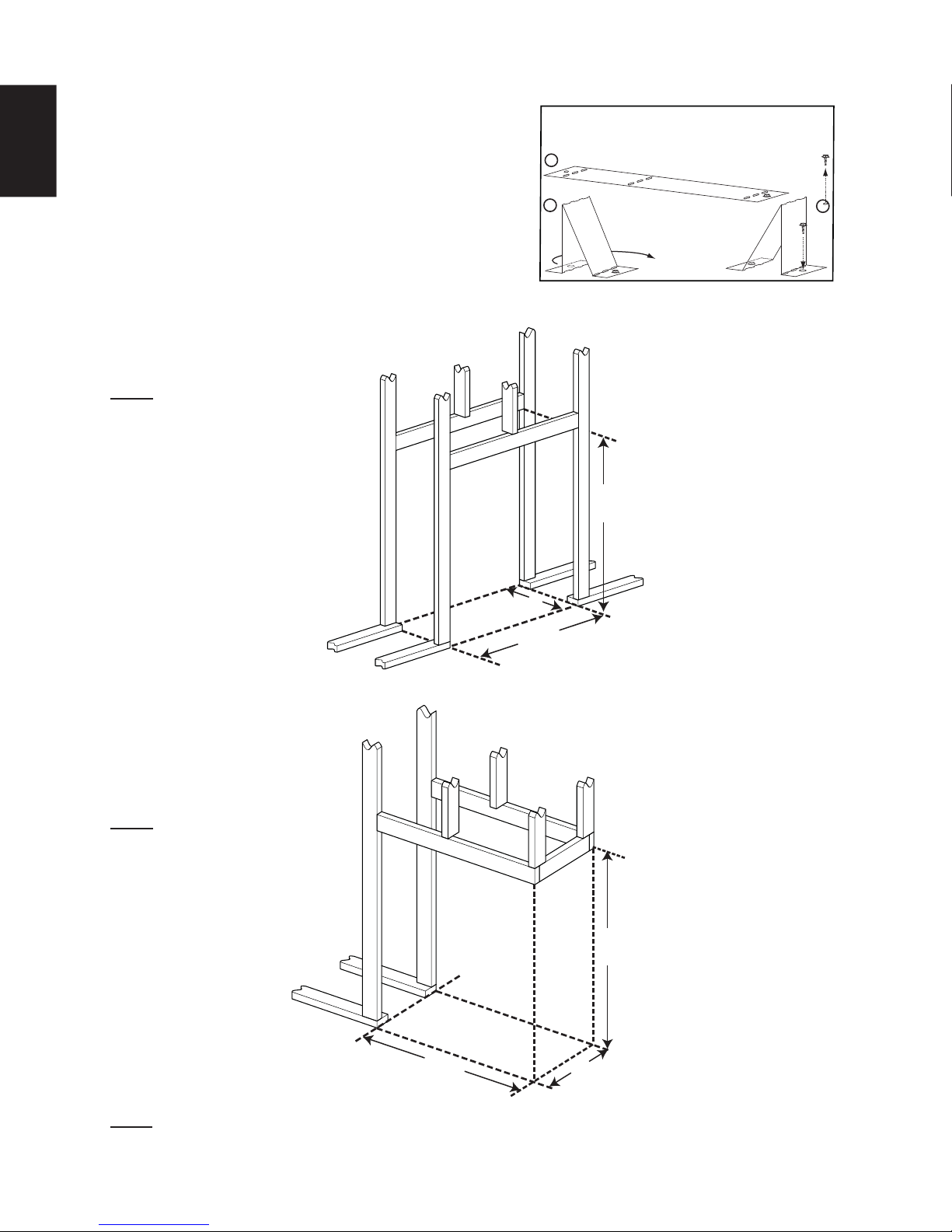
5.1 FRAMING
5.1.1 SEE-THRU FRAMING
This appliance is supplied with four stand-offs. For
convenience the stand-offs have been shipped fl at and
located on the top of the appliance. Before framing
ensure the stand-offs are bent up and screwed into
place ensuring a height of 10" (254mm). Stand-offs are
not used for structural support
NOTE: Dimension "A" should
measure 17 5/8" (447.7mm)
minimum (depending on the
fi nishing material thickness)
STAND-OFFS
Bend and secure the stand-offs as
A
B
illustrated
1
42
/2
”
(1079.5mm)
:
C
5.1.2 PENINSULA FRAMING
NOTE: Dimension "A" should
measure 17 5/8" (447.7mm)
minimum (depending on the
fi nishing material thickness)
A
3
40
/4
”
(1035.1mm)
1
42
/
2
”
(1079.5mm)
NOTE: All framing dimensions are based on the fi nishing material supports position. Framing may change
depending on the fi nishing material thickness. (See "FINISHING SUPPORT ADJUSTMENT" section).
W415-1150 / 02.28.13
3
38
/
8
”
(974.7mm)
A
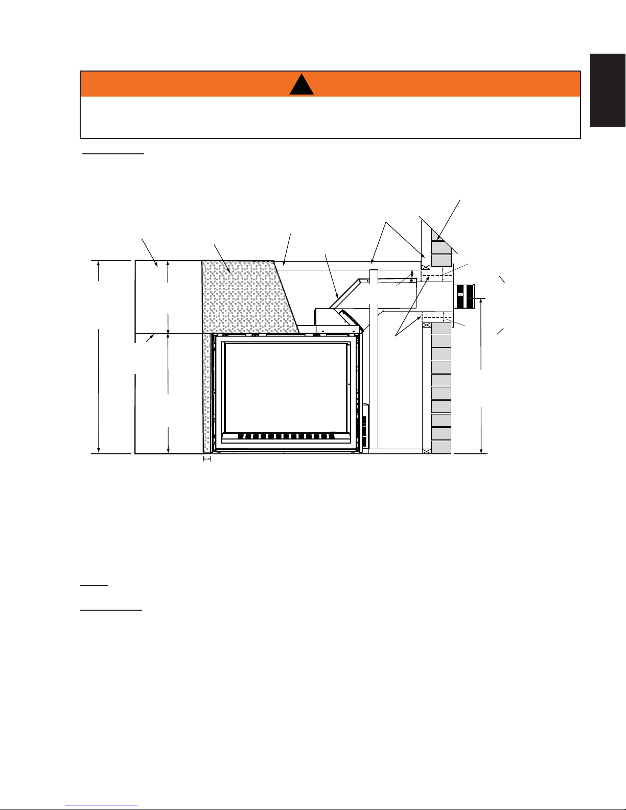
5.2 MINIMUM CLEARANCE TO COMBUSTIBLE ENCLOSURES
!
WARNING
THE FRONT OF THE APPLIANCE MUST BE FINISHED WITH ANY NON-COMBUSTIBLE MATERIALS
SUCH AS BRICK, MARBLE, GRANITE, ETC., AS LONG AS THESE MATERIALS NEVER OVERHANG
INTO THE APPLIANCE OPENING.
IMPORTANT: The CHD4 requires a minimum inside enclosure height of 46” (1168.4mm), measured from the
bottom of the appliance. For temperature requirements, this area must be left unobstructed.
NON-COMBUSTIBLE
27
EN
46” (1168.4mm)
MINIMUM
ENCLOSURE
HEIGHT
TOP OF
APPLIANCE
OPENING
COMBUSTIBLE
15 3/4”
(400.1mm)
MINIMUM
30 1/4”
(768.4mm)
MINIMUM
CEMENT
BOARD
2” (50.8mm)
TOP OF
ENCLOSURE
VENT HEAT SHIELD
COMBUSTIBLE
3”(76.2mm)
MIN
FIRESTOP
3”
(76.2mm)
2”
(50.8mm)
39” (990.6mm)
MINIMUM
PLUS RISE**
0” (0mm) IF
NON-COMBUSTIBLE
FINISHING IS USED,
SUCH AS BRICK
AND STONE
* Within the appliance enclosure a minimum 3” (76.2mm) clearance between the top of the vent pipe and
combustible materials is required. All other clearances within the enclosure, including where the vent pipe exits
the enclosure are subject to 2” (50.8mm)to the sides and bottom and 3” (76.2mm) to the top for horizontal and
1” (25.4mm) for vertical.
** See venting section.
NOTE: THIS APPLIANCE IS NOT LOAD BEARING.
IMPORTANT: The fi restop assembly provided must be used when the vent pipes pass through any
walls or are terminated horizontally.
W415-1150 / 03.07.13
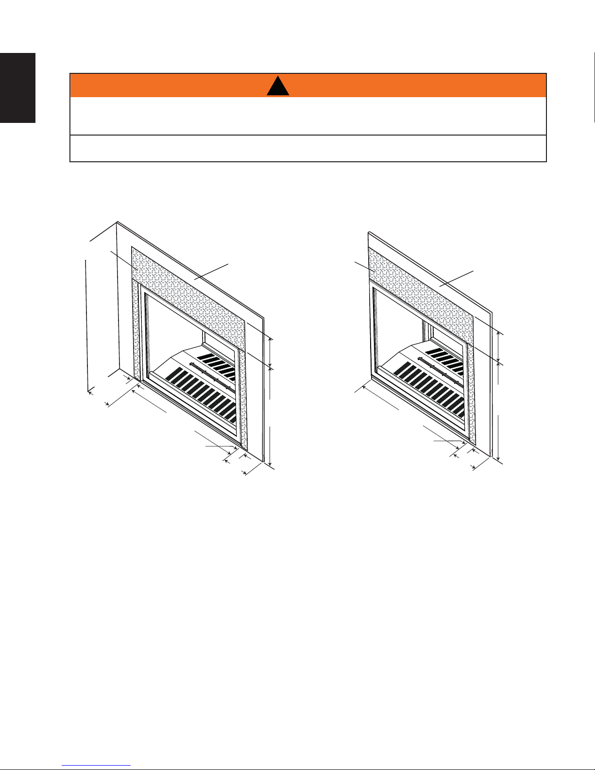
28
5.3 INSTALLING CEMENT BOARD
EN
!
WARNING
A NON-COMBUSTIBLE FINISHING MATERIAL BORDER, SUCH AS BRICK, MARBLE, GRANITE,
ETC. IS REQUIRED. FINISHING WITH JUST CEMENT BOARD TO THE SIDES AND TOP OF THE
APPLIANCE IS NOT ALLOWED.
THE SURFACE ABOVE THE APPLIANCE GETS VERY HOT. IF PROPER FINISHING MATERIALS ARE
NOT USED, CRACKING CAN OCCUR.
If only a painted surface is desired, a full single sheet of Wonder Board cement board must be used above the
door opening. We recommend the cement board to be cut and seamed as per illustrated below, when fi nishing
the entire surface with a non-combustible decorative fi nishing material.
See-Thru Peninsula
CEMENT
BOARD
SIDE
WALL
COMBUSTIBLE
FINISH MATERIAL
15 3/4”
(400.1mm)
CEMENT
BOARD
COMBUSTIBLE
FINISH MATERIAL
15 3/4”
(400.1mm)
2”
(50.8mm)
6”
(152.4mm)
MIN.
1
36
/
2
”
(927.1mm)
2”(50.8mm)
6” (152.4mm)
MIN. TO A
SIDE WALL
1
30
/
4
”
(768.4mm)
1
/
2
”
36
(927.1mm)
2”(50.8mm)
6” (152.4mm)
MIN. TO A
SIDE WALL
1
30
/
4
”
(768.4mm)
Joint Compound where required
Joint compounds such as Durabond 90 and tapes that are resilient to heat and cracking should be used when
taping and mudding seams.
Setting tiles and grouting
We recommend you use tiles with a dry butt joint to be installed using a two-part mortar with an acrylic latex
additive, such as Mapei Kerabond/Kerlastic, to allow for slight movement in the normal operation of the
appliance.
If grout is used between the tiles, a polymer-based grout, such as Mapei Ultracolour plus, is recommended.
Primer/Paint
For a painted surface, use a 100% acrylic latex primer and fi nish coat. Paints may discolour.
W415-1150 / 02.28.13
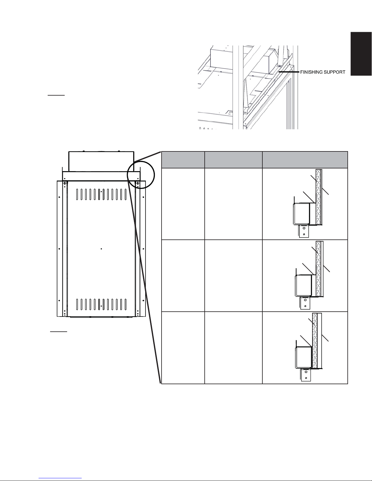
5.3.1 FINISHING SUPPORT ADJUSTMENT
29
Depending on the fi nishing material we have allowed
from 0" (0mm) to 3/4" (19mm) of adjustment after
the 1/2" (12.7mm) cement board has been installed.
Loosen the 8 screws on each fi nishing support.
Adjust the fi nishing support to the desired position.
NOTE: Peninsula models have one end support
that can also be adjusted by loosening the two
screws.
SIDE VIEW
FINISHING
MATERIAL
1/4" (6.4mm) 1/2" (12.7mm)
FINISH SUPPORT
POSITION
1/2" Cement
Board
Finish support
EN
1/4"
Finishing
Material
NOTE: Framing dimension "A"
will be affected as the fi nishing
supports are adjusted outwards.
(Refer to "FRAMING" section".
1/2" (12.7mm) 1/4" (6.4mm)
3/4" (19.1mm) Flush 0" (0mm)
1/2" Cement
Board
Finish support
1/2"
Finishing
Material
1/2" Cement
Board
Finish support
3/4"
Finishing
Material
W415-1150 / 03.07.13
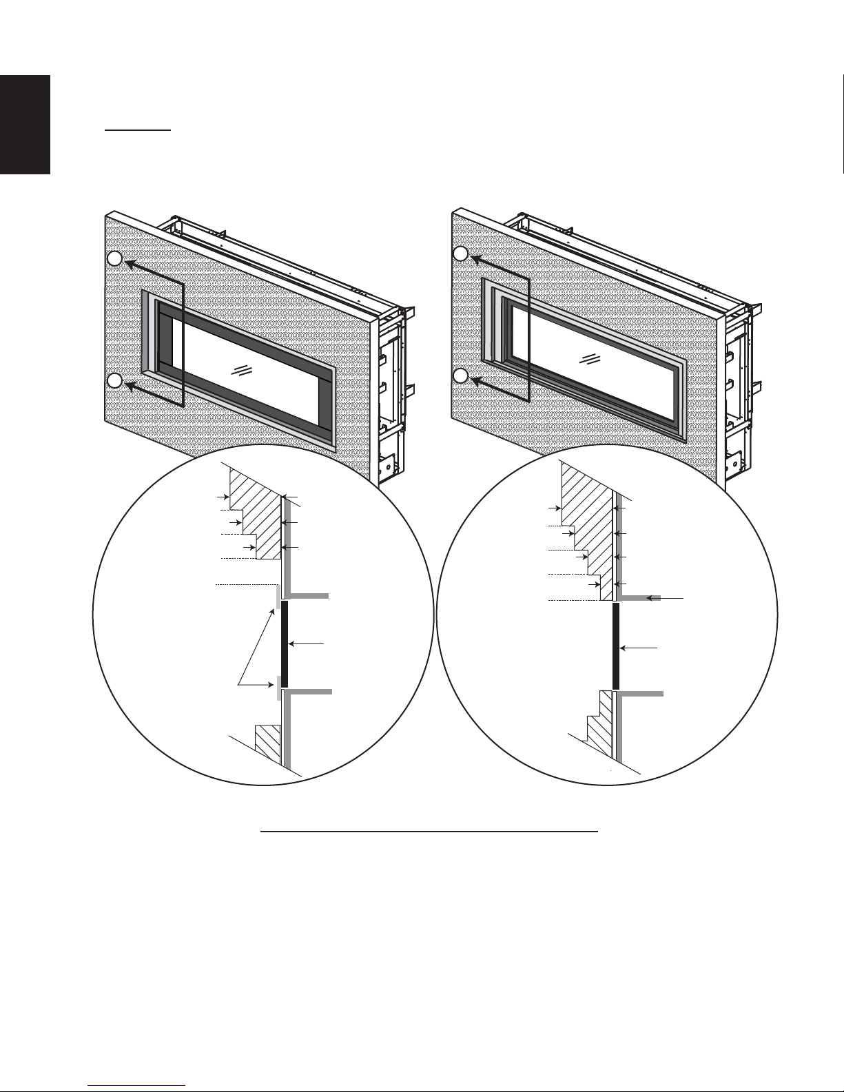
30
5.4 NON-COMBUSTIBLE FACING MATERIAL
EN
WARNING: Non-combustible facing material must not project more than 1” (24.5mm) from the face of the door
(all four sides). If greater projections are desired, increase the clearance to the sides and top by 2” (50.8mm)
for every additional 1” (25.4mm) of projection. If using an optional surround, then 2” (50.8mm) clearance from
the surround is required before projecting out a maximum 2” (50.8mm). If greater projections are desired,
increase the clearance from the surround by 2” (50.8mm) for every 1” (25.4mm) of additional projection.
A
A
B
B
4”
6” (152.4mm)
4” (101.6mm)
2” (50.8mm)
0” (0mm)
(101.6mm)
3” (76.2mm)
2” (50.8mm)
TOP OF
APPLIANCE
6” (152.4mm)
4” (101.6mm)
2” (50.8mm)
0” (0mm)
4” (101.6mm)
3” (76.2mm)
2” (50.8mm)
1” (25.4mm)
TOP OF
APPLIANCE
OPTIONAL
SURROUND
SECTION A - A SECTION B - B
DOOR
DOOR
71.5A
W415-1150 / 02.28.13
 Loading...