

Continental Fireplaces CHD35NT, CHD35PT, CHD40PT, CHD46PT, CHD40NT Installation And Operating Instructions Manual
...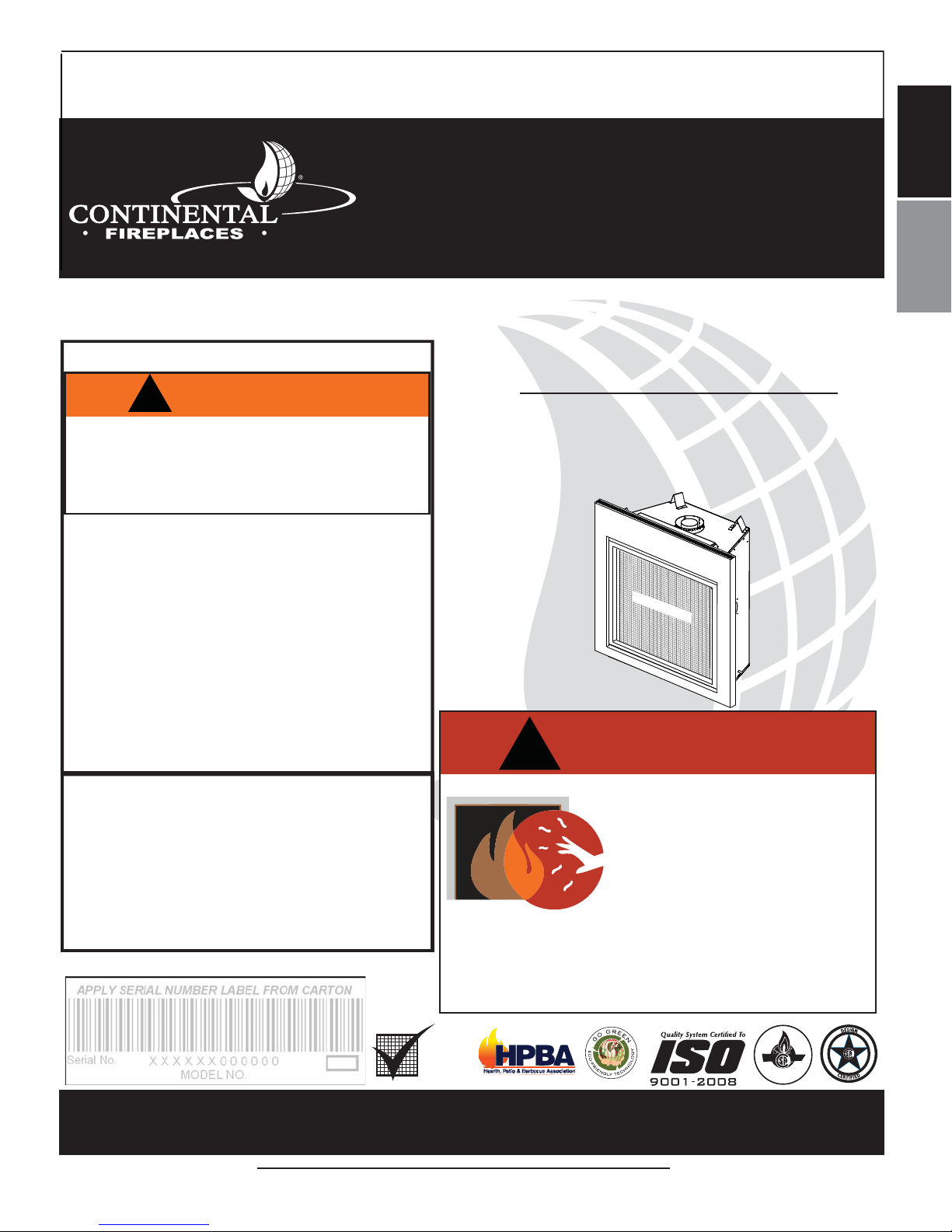
INSTALLER: LEAVE THIS MANUAL WITH THE APPLIANCE.
CONSUMER: RETAIN THIS MANUAL FOR FUTURE REFERENCE.
NEVER LEAVE CHILDREN OR OTHER AT RISK INDIVIDUALS ALONE WITH THE APPLIANCE.
INSTALLATION AND
EN
OPERATING INSTRUCTIONS
CONFORMS TO AMERICAN NATIONAL STANDARDS: ANSI Z21.50, CERTIFIED TO CANADIAN CSA 2.22 FOR VENTED GAS FIREPLACES.
CERTIFIED FOR CANADA AND UNITED STATES USING ANSI/CSA METHODS.
SAFETY INFORMATION
!
WARNING
If the information in these instructions
are not followed exactly, a fi re or
explosion may result causing property
damage, personal injury or loss of life.
- Do not store or use gasoline or other fl ammable
vapors and liquids in the vicinity of this or any
other appliance.
- WHAT TO DO IF YOU SMELL GAS:
• Do not try to light any appliance.
• Do not touch any electrical switch; do not use
any phone in your building.
• Immediately call your gas supplier from a
neighbour’s phone. Follow the gas supplier’s
instructions.
• If you cannot reach your gas supplier, call the
fi re department.
- Installation and service must be performed by a
qualifi ed installer, service agency or the supplier.
This appliance may be installed in an
aftermarket, permanently located, manufactured
home (USA only) or mobile home, where not
prohibited by local codes.
This appliance is only for use with the type of
gas indicated on the rating plate. This appliance
is not convertible for use with other gases,
unless a certifi ed kit is used.
Decorative Product: Not for use as a heating appliance.
CHD35NT, CHD40NT &
CHD46NT
NATURAL GAS
CHD35PT, CHD40PT &
CHD46PT
PROPANE
SAFETY BARRIER
HDF35KSB ILLUSTRATED
!
A barrier designed to reduce the risk of burns from
the hot viewing glass is provided with this appliance
and shall be installed for the protection of children
and other at-risk individuals.
DANGER
HOT GLASS WILL CAUSE
BURNS.
DO NOT TOUCH GLASS UNTIL
COOLED.
NEVER ALLOW CHILDREN TO
TOUCH GLASS.
FR
PG
69
Wolf Steel Ltd., 24 Napoleon Rd., Barrie, ON, L4M 0G8 Canada /
103 Miller Drive, Crittenden, Kentucky, USA, 41030
Phone (705)721-1212 • Fax (705)722-6031 • www.continentalfi replaces.com • ask@continentalfi re.on.ca
$10.00
BARRIER
CERTIFIED
1.8D
W415-1348 / A / 07.17.15

EN
2
TABLE OF CONTENTS
1.0 INSTALLATION OVERVIEW 3
1.1 USING NON-COMBUSTIBLE MATERIAL 3
2.0 INTRODUCTION 4
2.1 DIMENSIONS 5
2.3 GENERAL INSTRUCTIONS 6
2.4 GENERAL INFORMATION 7
2.5 RATING PLATE INFORMATION 8
3.0 VENTING 9
3.1 VENTING LENGTHS AND COMPONENTS 9
3.2 TYPICAL VENT INSTALLATIONS 10
3.3 SPECIAL VENT INSTALLATIONS 11
3.3.1 PERISCOPE TERMINATION 11
3.3.2 CORNER TERMINATION 11
3.4 VENT TERMINAL CLEARANCES 12
3.5 VENT APPLICATION FLOW CHART 13
3.6 DEFINITIONS 13
3.7 ELBOW VENT LENGTHS 13
3.8 HORIZONTAL TERMINATION 14
3.9 VERTICAL TERMINATION 16
3.10 CO-AXIAL TO CO-LINEAR VENTING 18
4.0 INSTALLATION 19
4.1 WALL AND CEILING PROTECTION 19
4.1.1 HORIZONTAL INSTALLATION 20
4.1.2 VERTICAL INSTALLATION 20
4.2 USING FLEXIBLE VENT COMPONENTS 21
4.2.1 HORIZONTAL AIR TERMINAL INSTALLATION 21
4.2.2 VERTICAL AIR TERMINAL INSTALLATION 22
4.3 USING RIGID VENT COMPONENTS 23
4.3.1 HORIZONTAL AIR TERMINAL INSTALLATION 23
4.3.2 EXTENDED HORIZONTAL AIR TERMINAL INSTALLATION 23
4.3.3 VERTICAL VENTING INSTALLATION 24
4.4 MOBILE HOME 25
4.5 ACCESS PANEL FOR GAS LINE CONNECTION 25
4.6 GAS INSTALLATION 26
5.0 FRAMING 27
5.1 MINIMUM CLEARANCE TO COMBUSTIBLES 29
5.2 MINIMUM CLEARANCE TO COMBUSTIBLE ENCLOSURES 30
5.3 ALCOVE INSTALLATION 32
5.4 MINIMUM COMBUSTIBLE MANTEL CLEARANCES 33
5.5 NON-COMBUSTIBLE FACING MATERIAL 33
6.0 FINISHING 34
6.1 SAFETY SCREEN REMOVAL / INSTALLATION 34
6.3 FRONT SURROUND INSTALLATION 35
6.2 GLASS DOOR REMOVAL / INSTALLATION 35
6.4 LOG PLACEMENT 36
6.5 GLOWING EMBER PLACEMENT 38
6.6 CHARCOAL EMBERS 38
6.7 OPTIONAL VERMICULITE 38
6.10 LAVA ROCK 38
6.8 OPTIONAL CHARCOAL LUMPS (STANDARD ON CHD46) 38
6.9 LOGO PLACEMENT 38
7.0 OPTIONAL BLOWER INSTALLATION 39
7.1 ACCESSING THE BLOWER 39
7.2 INSTALLING THE BLOWER 40
8.0 WIRING DIAGRAM / ELECTRICAL INFORMATION 41
8.1 WIRING REQUIREMENTS 41
8.2 OPTIONAL ACCESSORIES REQUIREMENTS 41
8.3 JUNCTION BOX INSTALLATION 42
8.4 WIRING DIAGRAM 43
9.0 OPERATION 44
10.0 ADJUSTMENT 45
10.1 PRESSURE ADJUSTMENT 45
10.2 VENTURI ADJUSTMENT 45
10.3 FLAME CHARACTERISTICS 46
11.0 MAINTENANCE 46
11.1 ANNUAL MAINTENANCE 47
11.2 DOOR GLASS REPLACEMENT 48
11.3 CARE OF GLASS 48
11.4 CARE OF PLATED PARTS 48
12.0 REPLACEMENT PARTS 49
13.0 CHD35 OVERVIEW 50
14.0 CHD35 VALVE TRAIN ASSEMBLY 51
15.0 CHD35 ACCESSORIES 52
16.0 CHD35 ACCESSORIES (PAGE 2) 53
17.0 CHD40 OVERVIEW 54
18.0 CHD40 VALVE TRAIN ASSEMBLY 55
19.0 CHD40 ACCESSORIES 56
NOTE: Changes, other than editorial, are denoted by a vertical line in the margin.
W415-1348 / A / 07.17.15
20.0 CHD40 ACCESSORIES (PAGE 2) 57
21.0 CHD46 OVERVIEW 58
22.0 CHD46 VALVE TRAIN ASSEMBLY 59
23.0 CHD46 ACCESSORIES 60
24.0 CHD46 ACCESSORIES (PAGE 2) 61
25.0 TROUBLESHOOTING 62
26.0 WARRANTY 64
27.0 SERVICE HISTORY 65
28.0 NOTES 66
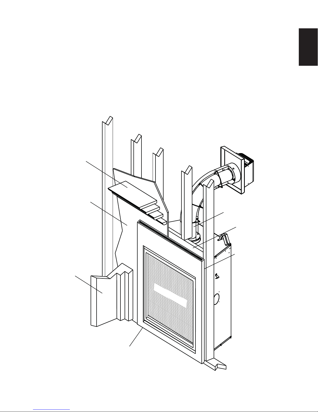
1.0 INSTALLATION OVERVIEW
1.1 USING NON-COMBUSTIBLE MATERIAL
Mantel, see “MINIMUM
MANTEL CLEARANCES” section.
3
EN
Enclosures, see the
section “MINIMUM
CLEARANCES TO
COMBUSTIBLE
ENCLOSURES”
section for drywall (or
other combustible
material).
Framing, see
“FRAMING”
section.
Side
Wall
SAFETY BARRIER
Venting, see “VENTING”
section.
Framing, see “FRAMING”
section.
Enclosures, see the
section “MINIMUM
CLEARANCE TO COMBUSTIBLE ENCLOSURES” section for
non-combustible materials
such as tile, marble,
granite, etc.
Rating plate, see “RATING
PLATE INFORMATION”
section.
W415-1348 / A / 07.17.15

4
2.0 INTRODUCTION
EN
• THIS APPLIANCE IS HOT WHEN OPERATED AND CAN CAUSE SEVERE BURNS IF CONTACTED.
• ANY CHANGES OR ALTERATIONS TO THIS APPLIANCE OR ITS CONTROLS CAN BE DANGEROUS AND IS
PROHIBITED.
• Do not operate appliance before reading and understanding operating instructions. Failure to operate appliance
according to operating instructions could cause fi re or injury.
• Risk of fi re or asphyxiation do not operate appliance with fi xed glass removed.
• Do not connect 110 volts to the control valve.
• Risk of burns. The appliance should be turned off and cooled before servicing.
• Do not install damaged, incomplete or substitute components.
• Risk of cuts and abrasions. Wear protective gloves and safety glasses during installation. Sheet metal edges may
be sharp.
• Do not burn wood or other materials in this appliance.
• Children and adults should be alerted to the hazards of high surface temperature and should stay away to
avoid burns or clothing ignition.
• Young children should be carefully supervised when they are in the same room as the appliance.
Toddlers, young children and others may be susceptible to accidental contact burns. A physical barrier
is recommended if there are at risk individuals in the house. To restrict access to an appliance, install an
adjustable safety gate to keep toddlers, young children and other at risk individuals out of the room and
away from hot surfaces.
• Clothing or other fl ammable material should not be placed on or near the appliance.
• Due to high temperatures, the appliance should be located out of traffi c and away from furniture and
draperies.
• Ensure you have incorporated adequate safety measure to protect infants/toddlers from touching hot surfaces.
• Even after the appliance is out, the glass and/or screen will remain hot for an extended period of time.
• Check with your local hearth specialty dealer for safety screens and hearth guards to protect children from hot
surfaces. These screens and guards must be fastened to the fl oor.
• Any safety screen, guard or barrier removed for servicing the appliance, must be replaced prior to operating
the appliance.
• The appliance is a vented gas-fi red appliance. Do not burn wood or other materials in the appliance
• It is imperative that the control compartments, burners and circulating blower and its passageway in the appliance
and venting system are kept clean. The appliance and its venting system should be inspected before use and at
least annually by a qualifi ed service person. More frequent cleaning may be required due to excessive lint from
carpeting, bedding material, etc. The appliance area must be kept clear and free from combustible materials,
gasoline and other fl ammable vapors and liquids.
• Under no circumstances should this appliance be modifi ed.
• This appliance must not be connected to a chimney fl ue pipe serving a separate solid fuel burning appliance.
• Do not use this appliance if any part has been under water. Immediately call a qualifi ed service technician to inspect
the appliance and to replace any part of the control system and any gas control which has been under water.
• Do not operate the appliance with the glass door removed, cracked or broken. Replacement of the glass should be
done by a licensed or qualifi ed service person.
• Do not strike or slam shut the appliance glass door.
• When equipped with pressure relief doors, they must be kept closed while the appliance is operating to prevent
exhaust fumes containing carbon monoxide, from entering into the home. Temperatures of the exhaust escaping
through these openings can also cause the surrounding combustible materials to overheat and catch fi re.
• Only doors / optional fronts certifi ed with the appliance are to be installed on the appliance.
• Keep the packaging material out of reach of children and dispose of the material in a safe manner. As with all plastic
bags, these are not toys and should be kept away from children and infants.
• As with any combustion appliance, we recommend having your appliance regularly inspected and serviced as well
as having a Carbon Monoxide Detector installed in the same area to defend you and your family against Carbon
Monoxide.
• Ensure clearances to combustibles are maintained when building a mantel or shelves above the appliance.
Elevated temperatures on the wall or in the air above the appliance can cause melting, discolouration or damage of
decorations, a T.V. or other electronic components.
• A barrier designed to reduce the risk of burns from the hot viewing glass is provided with this appliance and
shall be installed.
• If the barrier becomes damaged, the barrier shall be replaced with the manufacturer’s barrier for this
appliance.
• Installation and repair should be done by a qualifi ed service person. The appliance should be inspected
before use and at least annually by a professional service person. More frequent cleaning may be required
due to excessive lint from carpeting, bedding material, etc. It is imperative that control compartments,
burners and circulating air passageways of the appliance be kept clean.
W415-1348 / A / 07.17.15
!
WARNING
3.2C
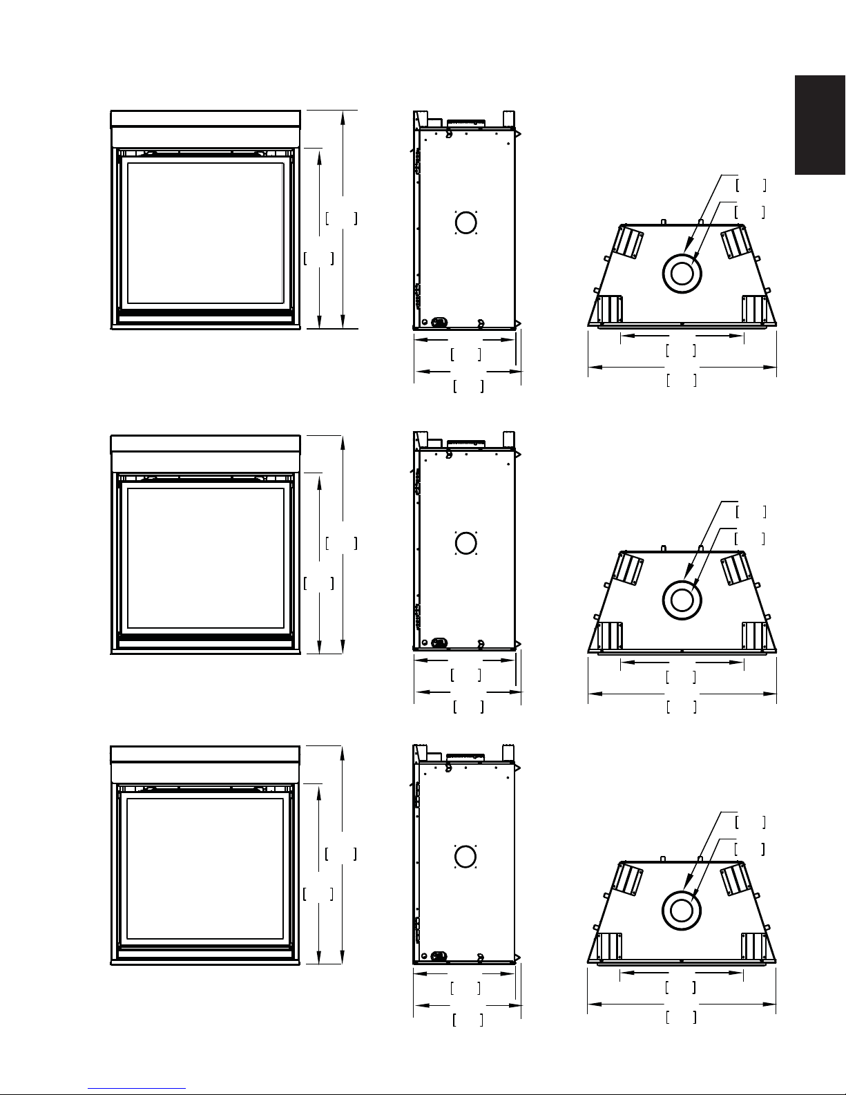
2.1 DIMENSIONS
1041mm
33 3/4"
857mm
41"
Ø
7 "
178mm
Ø
4 "
102mm
5
EN
CHD35 ILLUSTRATED
HD35 ILLUSTRATED
CHD40 ILLUSTRATED
HD40 ILLUSTRATED
1041mm
33 3/4"
857mm
41"
20”
508mm
20 1/2”
521mm
20”
508mm
20 1/2”
521mm
23”
584mm
35 1/4”
895mm
28”
711mm
40 1/4”
1022mm
Ø
7 "
178mm
Ø
4 "
102mm
CHD46 ILLUSTRATED
HD46 ILLUSTRATED
1041mm
33 3/4"
857mm
41"
20”
508mm
20 1/2”
521mm
Ø
178mm
Ø
102mm
34”
864mm
46 1/4”
1175mm
W415-1348 / A / 07.17.15
7 "
4 "
6
A
A
2.3 GENERAL INSTRUCTIONS
EN
ALWAYS LIGHT THE PILOT WHETHER FOR THE FIRST TIME OR IF THE GAS SUPPLY HAS RUN OUT,
PROVIDE ADEQUATE CLEARANCE FOR SERVICING AND OPERATING THE APPLIANCE.
NEVER OBSTRUCT THE FRONT OPENING OF THE APPLIANCE.
OBJECTS PLACED IN FRONT OF THE APPLIANCE MUST BE KEPT A MINIMUM OF 48” (1219mm) FROM
SURFACES AROUND AND ESPECIALLY ABOVE THE APPLIANCE CAN BECOME HOT. AVOID CONTACT
HIGH PRESSURE WILL DAMAGE VALVE. DISCONNECT GAS SUPPLY PIPING BEFORE PRESSURE TESTING GAS
LINE AT TEST PRESSURES ABOVE 1/2 PSIG. CLOSE THE MANUAL SHUT-OFF VALVE BEFORE PRESSURE
TESTING GAS LINE AT TEST PRESSURES EQUAL TO OR LESS THAN 1/2 PSIG (35 mb).
USE ONLY WOLF STEEL APPROVED OPTIONAL ACCESSORIES AND REPLACEMENT PARTS WITH THIS APPLIANCE.
USING NON-LISTED ACCESSORIES (BLOWERS, DOORS, LOUVRES, TRIMS, GAS COMPONENTS, VENTING
COMPONENTS, ETC.) COULD RESULT IN A SAFETY HAZARD AND WILL VOID THE WARRANTY AND CERTIFICATION.
THIS GAS APPLIANCE SHOULD BE INSTALLED AND SERVICED BY A QUALIFIED INSTALLER to
conform with local codes. Installation practices vary from region to region and it is important to know the
specifi cs that apply to your area, for example in Massachusetts State:
• This product must be installed by a licensed plumber or gas fi tter when installed within the commonwealth
of Massachusetts.
• The appliance damper must be removed or welded in the open position prior to installation of an appliance
insert or gas log.
• The appliance off valve must be a “T” handle gas cock.
• The fl exible connector must not be longer than 36 inches (914mm).
• A Carbon Monoxide detector is required in all rooms containing gas fi red appliances.
• The appliance is not approved for installation in a bedroom or bathroom unless the unit is a direct vent
sealed combustion product.
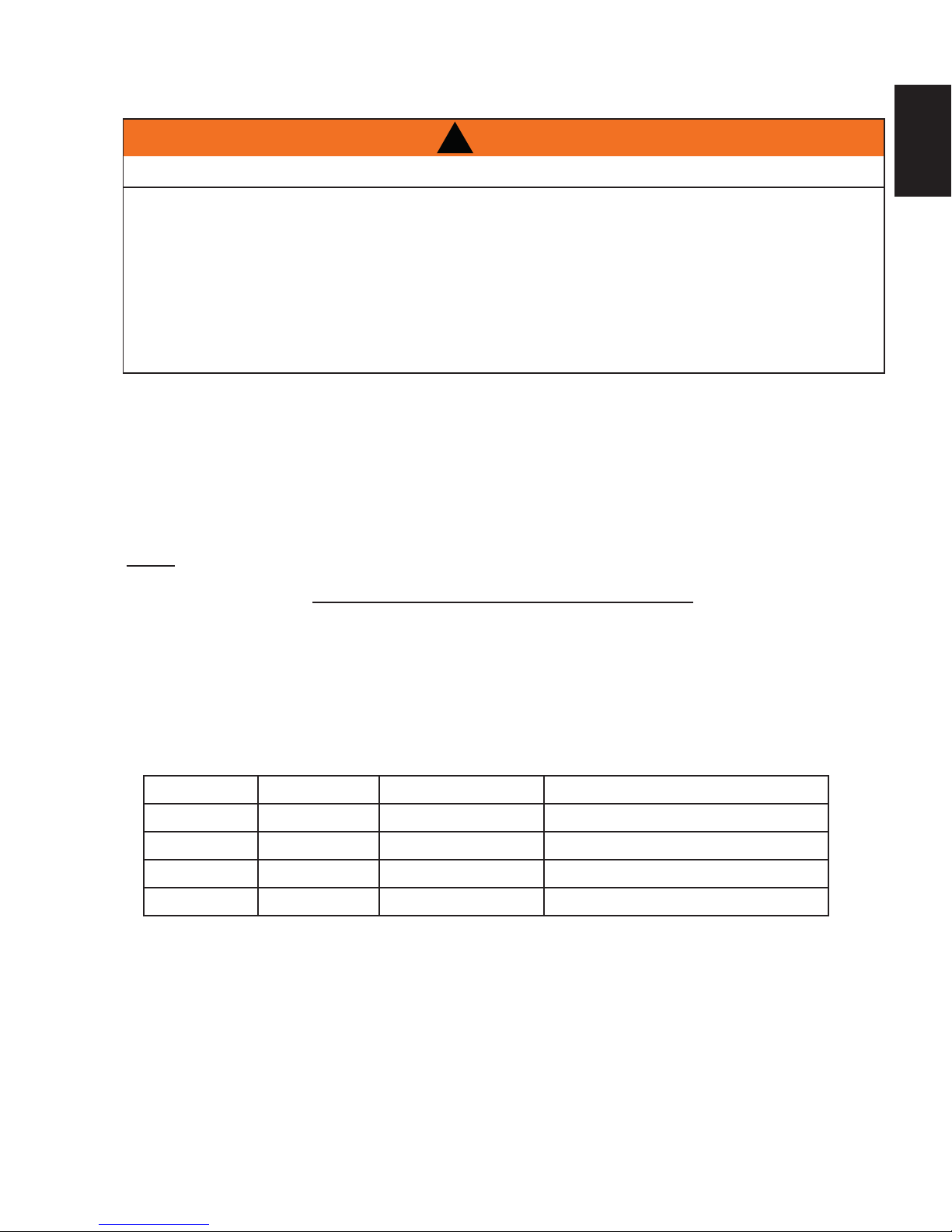
!
WARNING
WITH THE GLASS DOOR OPENED OR REMOVED.
PROVIDE ADEQUA TE VENTILA TION.
THE FRONT FACE OF THE APPLIANCE.
WHEN THE APPLIANCE IS OPERATING.
FIRE RISK. EXPLOSION HAZARD.
The installation must conform with local codes or, in
absence of local codes, the National Gas and Propane
Installation Code CSA B149.1 in Canada, or the National
Fuel Gas Code, ANSI Z223.1 / NFPA 54 in the United
States. Suitable for mobile home installation if installed in
accordance with the current standard CAN/CSA Z240MH
Series, for gas equipped mobile homes, in Canada or
NSI Z223.1 and NFPA 54 in the United States.
s long as the required clearance to combustibles is
maintained, the most desirable and benefi cial location
for an appliance is in the center of a building, thereby
allowing the most effi cient use of the heat created. The location of windows, doors and the traffi c fl ow in the
room where the appliance is to be located should be considered. If possible, you should choose a location
where the vent will pass through the house without cutting a fl oor or roof joist.
If the appliance is installed directly on carpeting, vinyl tile or other combustible material other than wood
fl ooring, the appliance shall be installed on a metal or wood panel extending the full width and depth.
Some appliances have optional fans or blowers. If an optional fan or blower is installed, the junction box must
be electrically connected and grounded in accordance with local codes, use the current CSA C22.1 Canadian
Electrical Code in Canada or the ANSI/NFPA 70 National Electrical code in the United States.
www.ncertied.org
We suggest that our gas
hearth products be installed
and serviced by professionals
who are certied in the U.S.
by the National Fireplace
®
Institute
(NFI) as NFI Gas
Specialists
4.1B
W415-1348 / A / 07.17.15
2.4 GENERAL INFORMATION
FOR YOUR SATISFACTION, THIS APPLIANCE HAS BEEN TEST-FIRED TO ASSURE ITS OPERATION
AND QUALITY!
This appliance is approved for bathroom, bedroom and bed-sitting room installations and is suitable for mobile
home installations.
These appliances are equipped with tempered glass. Replacement glass must be obtained from your authorized dealer / distributor and is identifi ed in the replacement parts list. Do not substitute materials.
This appliance is not convertible for use with other gases, unless a certifi ed kit is used.
Expansion / contraction noises during heating up and cooling down cycles are normal and are to be expected.
Changes in fl ame appearance from “HI” to “LO” is more evident in natural gas than in propane.
Use only accessories designed for and listed with your specifi c appliance.
High Elevations
Input ratings are shown in Btu per hour and are certifi ed without de-rating up to 4,500 feet (1372m) above sea
level. For Installations at the elevations above 4,500 feet (1372m) and in the absence of specifi c recommenda-
tions from the local authority having jurisdiction, the high altitude input rating shall be reduced at the rate of 4%
for each additional 1,000 feet (305m).
7
EN
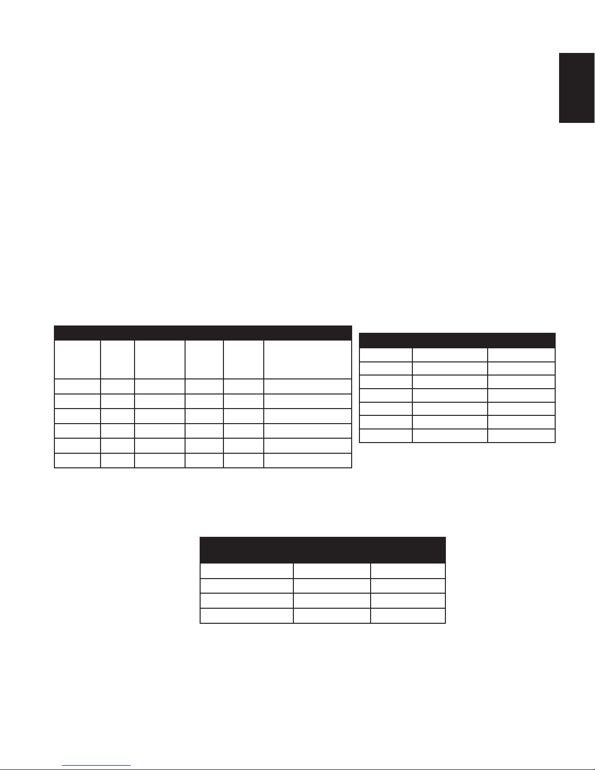
GAS SPECIFICATIONS
Model Fuel Gas
Control
Max.
Input
BTU/h
Min.
Input
BTU/h
Air shutter set-
ting
HD35NT Nat IPI Hi/Lo 25,000 17,500 1/8” (3mm) Open
HD35PT Prop* IPI Hi/Lo 25,000 17,500 5/16” (8mm) Open
HD40NT Nat IPI Hi/Lo 27,000 18,900 1/8” (3mm) Open
HD40PT Prop* IPI Hi/Lo 27,000 18,900 3/8” (10mm) Open
HD46NT Nat IPI Hi/Lo 30,000 21,000 1/8” (3mm) Open
HD46PT Prop* IPI Hi/Lo 30,000 21,000 3/8” (10mm) Open
IPI - Intermittent Pilot Ignition System
* Using conversion kit
** Maximum Values
Conversions must be made by a qualifi ed service
technician using Wolf Steel specifi ed and approved parts.
GAS INLET AND MANIFOLD
PRESSURES
Natural Propane
Minimum Inlet 4.5” (11mb) w.c. 11” (27mb) w.c.
Maximum Inlet 7” (17mb) w.c. 13” (32mb) w.c.
Manifold Pressure 3.5” (9mb) w.c. 10” (25mb) w.c.
EFFICIENCY RATINGS
Model Steady State(%) AFUE%**
HD35NT 82.1% 77.2%
HD35PT 82.1% 77.2%
HD40NT 80.5% 76.3%
HD40PT 80.5% 76.3%
HD46NT 82.9% 79.2%
HD46PT 82.9% 79.2%
The optional heat circulating blower is supplied with a cord.
The junction box must be electrically connected and grounded in accordance with local codes. In the absence
of local codes, use the current CSA C22.1 Canadian Electrical Code in Canada or the ANSI/NFPA 70 National
Electrical Code in the United States.
This appliance is equipped with a power back up control system. Two 1.5 volt “D” batteries (not supplied) are
required for the battery pack included in the system. Use Alkaline batteries only.
W415-1348 / A / 07.17.15
EN
OLUMNN
P4:P4:
%65.1%
H TH
SIS
UNUN
OIT O
NNLLYY
WITHWITH
SSURE:MANIFOLD PR E
10" WA
PRESSION AU COLLECTEUPRESSION AU
MINIMUM SUPPLY PRESINIMUM SUPPL
PRESSION D'ALIMENSSION D'ALIME
MAXIMUM SUPPLYMAXIMUM SUPPLY
PRESSION D'ALPRESSION D'A
P4:P4:
%65.1%
TIONTION
ATIONATION
T
ATION REDUITEATION REDUITE
0-4500FT (0-1370m)0-4500FT (0-1370m)
h30,000 BTU/h
21,000 BTU/h
D46PT
PropanePropan
PP
OO
URUR
I
NSNS
TTALLAA
TIOTTAALLLLAATT
OIONNDANSS
UNEUNE
M
/
CSCS
AA
ZZ
240M240M
H
SÉRR
IEEDEDE M M
AA
S
O
LAANNOORRMMEE
DED
SÉCURÉCUR
II
TÉTÉEETTD
C
OO
L
EE
CASCAS O OÙÙC
ECETTENNOO
RR
MMEE
DES
ÉÉ
TATA
TS-UTS-U
I
TÈRE
DEDE
MM
SESURES
DEDE
SÉCURSÉ
TÉ
CC
OO
NTRE
NTRE
S
SS
I
TESTES
EETT L L
ESESCCOMM
UNAUTÉSUNAUTÉS,,GD-565
K
T
, L
FOYERYER
ESES
T T
CC
OO
NFOORRMMEEÀÀ L L
AA
EULMENT AVEC BARRIÈRE W565-0175. SUIVEZIÈRE W565-0175. SUIVE
,
CE FOCE F
NVEN
T T
TOP/ DESSUS DE L’ÉVENT TOP/ DESSUS DE L’ÉVENT
0 0
VENT BOTTOM / DESSOUS DE L’ÉVENVENT BOTTOM / DESSOUS DE L’É
U 13"*
13"*
IZONTAL EXTENSION / EXTENSION HORIZO
ON MA
MANNUALUAL FFOROR
GG
RREAEATTER ER
EXEND
'II
ANSTA
LL
LALA
TIOTIO
8
63.3%
CHD35
64.3%
CHD40
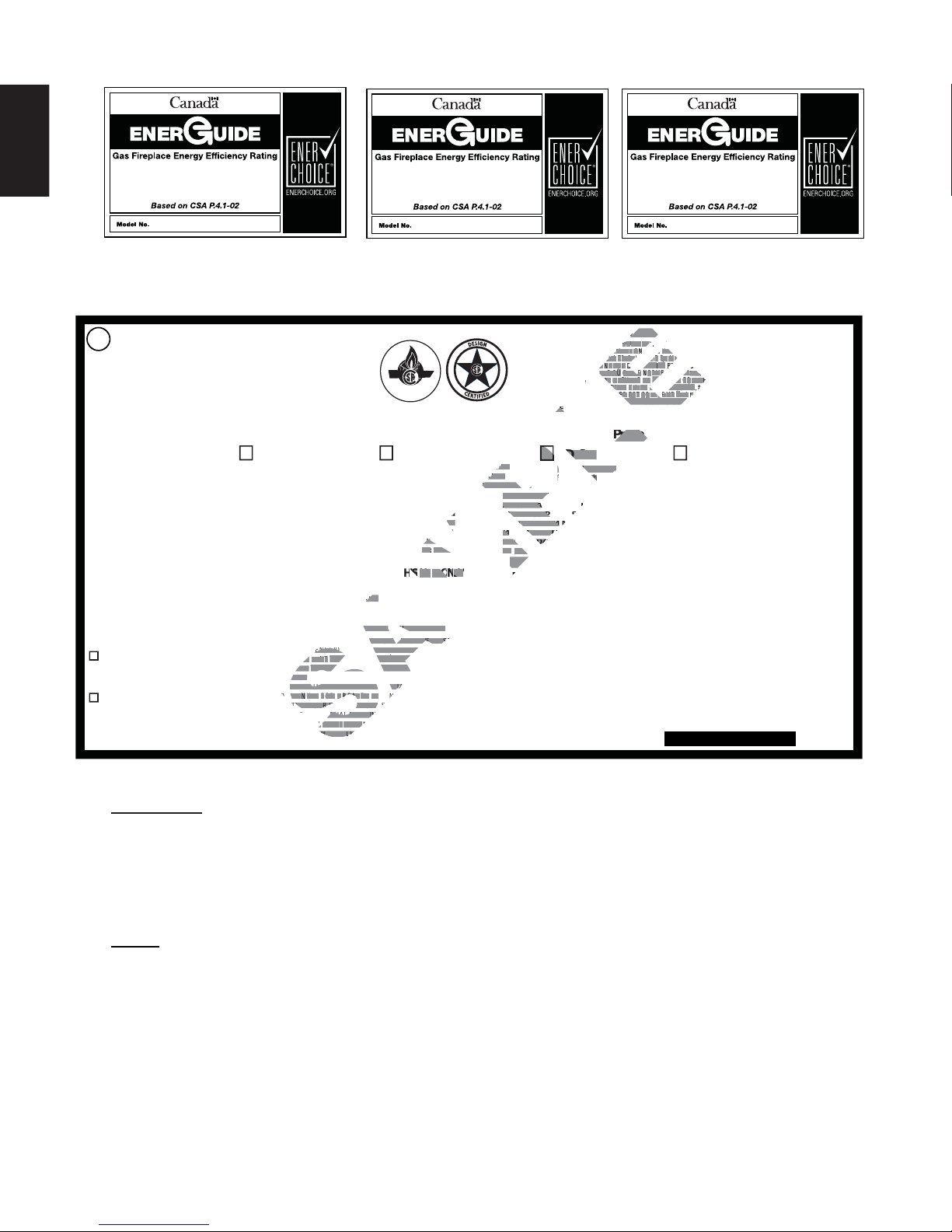
2.5 RATING PLATE INFORMATION
DIRECT VENT GAS FIREPLACE . SUITABLE FOR BEDROOM, BATHROOM AND BED-SITTING
ROOM INSTALLATION. SUITABLE FOR MOBILE HOME INSTALLATION IF INSTALLED IN
ACCORDANCE WITH THE CURRENT STANDARD CAN/CSA Z240MH SERIES GAS EQUIPPED MOBILE
HOMES, IN CANADA OR IN THE UNITED STATES THE MANUFACTURED HOME CONTRUCTION
AND SAFETY STANDARD, TITLE 24 CFR, PART 3280. WHEN THIS US STANDARD IS NOT APPLICABLE
USE THE STANDARD FOR FIRE SAFETY CRITERIA FOR MANUFACTURED HOME INSTALLATIONS, SITES
AND COMMUNITIES, ANSI / NFPA 501A. WHEN INSTALLED WITH SCREEN KIT GD-565KT, THE FIREPLACE
COMPLIES WITH CGA CERTIFICATION REQUIREMENT CR95-006. FOR USE ONLY WITH BARRIER
W565-0175. FOLLOW THE INSTALLATION INSTRUCTIONS LOCATED IN THE INSTALLATION MANUAL.
THIS VENTE D G A S F IR EP LA C E I S N OT FO R US E WITH AIR FILTERS AND NOT
FOR USE WITH SOLID FUEL. FOR USE WITH GLASS DOORS CERTIFIED WITH THIS UNIT ONLY
WARNING: DO NOT ADD ANY MATERIAL TO THE APPLIANCE, WHICH WILL COME IN
CONTACT WITH THE FLAMES, OTHER THAN THAT SUPPLIED BY THE MANUFACTURER WITH
THE APPLIANCE.
DECORATIVE PRODUCT: NOT FOR USE AS A HEATING APPLIANCE
MINIMUM CLEARANCE TO COMBUSTIBLE MATERIALS / DEGAGEMENTS MINIMAUX DES MATERIAUX COMBUSTIBLES:
WOLF STEEL LTD.
24 Napoleon Rd. Barrie,
Ontario L4M 0G8 Canada
WOLF STEEL USA
103 Miller Drive,
Crittenden, Kentucky, USA, 41030
CONFORMS TO / CONFORME AUX: ANSI Z21.50-2014, CERTIFIED TO / CERTIFIE CSA 2.22-2014 VENTED GAS FIREPLACE / FOYER À GAZ VENTILÉ.ES:
CERTIFIED
CERTIFIED FOR
CERTIFIEE POUR
REFERENCE # 161746
REDUCED INPUT/ALIMENTATION REDUITE
P4: 65.1%
HD46NT
Natural Gas/Gaz Naturel Propane
CHD46NT
0-4500 FT (0-1370m)
30,000 BTU/h
21,000 BTU/h
MANIFOLD PRESSURE: 3.5” WATER COLUMN
PRESSIONAU COLLECTEUR: 3.5" D'UNE COLONNE D'EAU
PRESSION D'ALIMENTATION MINIMALE: 4.5" D'UNE COLONNE D'EAU
MINIMUM SUPPLY PRESSURE: 4.5" WATER COLUMN
MAXIMUM SUPPLY PRESSURE: 7.0" WATER COLUMN
PRESSION D'ATATION MAXIMALE: 7.0" D'UNE COLONNE D'EAU
I
TOP/DESSUS 0 RECESSED DEPTH / PROFONDEUR D'ENCASTRE 20½"
FLOOR / PLANCHER 0 VENT SIDES / COTES DE L'EVENT 1"
SIDES / COTES 0
ARRIERE 0 VENT BOTTOM / DESSOUS DE L’ÉVENT 1"
BACK/
MANTLE / MANTEAU 13"*
MAXIMUM HORIZONTAL EXTENSION / EXTENSION HORIZONTALE MAXIMALE: 2".
*
SEE INSTRUCTION MANUAL FOR GREATER EXTENSIONS SE RÉFÉRER AU
MANUEL
D'INSTRUCTION POUR DES EXTENSIONS PLUS GRANDES.
SEE OWNER'S INSTRUCTION MANUAL FOR MINIMUM AND MAXIMUM VENT LENGTHS.
SE RÉFÉRER AU MANUEL D'INSTALLATION DU PRO PRIÉTAIRE POUR LES LONGUEURS
D'EVACUATION MINIMALE EV MAXIMALE.
VENT TOP/ DESSUS DE L’ÉVENT 2"
VE
EXT
NST
CANADA USA
MODEL
ALTITUDE / ELEVATION
INPUT/ALIMENTATION
65.1
IT
65.1%
CHD46
FOYER À GAZ VENTILÉ. HOMOLOGUÉ POUR INSTALLATION DANS UNE CHAMBRE À COUCHER, UNE SALLE DE BAIN ET
UN STUDIO. APPROPRIÉ POUR INSTALLATION DANS UNE MAISON MOBILE SI SON INSTALLATION EST CONFORME AUX
EXIGENCES DE LA NORME CAN/CSA Z240MH SÉRIE DE MAISONS MOBILES ÉQUIPÉES AU GAZ, EN VIGUEUR AU CANADA,
OU AUX ÉTATS-UNIS, SELON LA NORME DE SÉCURITÉ ET DE CONSTRUCTION DE MAISONS MANUFACTURÉES, TITRE 24
CFR, SECTION 3280. DANS LE CAS OÙ CETTE NORME DES ÉTATS-UNIS NE PEUT ÊTRE APPLIQUÉE, SE RÉFÉRER À LA
NORME RELATIVE AU CRITÈRE DE MESURES DE SÉCURITÉ CONTRE L'INCENDIE POUR LES INSTALLATIONS DANS LES
MAISONS MANUFACTURÉES, LES SITES ET LES COMMUNAUTÉS, ANSI/NFPA 501A. LORSQU'IL EST INSTALLÉ AVEC LE
INCELLES GD-565KT, LE FOYER EST CONFORME À LA NORME DE CERTIFICATION DE L'ACG CR95-006.
PARE-ÉT
UNE UTILISER SEULMENT AVEC BARRIÈRE W565-0175. SUIVEZ LES INSTRUCTIONS D'INSTALLATION SE TROUVENT
DANS LE MANUEL D'INSTALLATION.
HD46PT
HD46PT
0-4500FT (0-1370m)
30,000 BTU/h
30,000 BTU/
MANIFOLD PR ESSURE: 10" WATER COLUMN
MANIFOLD PR E
PRESSION AU COLLECTEUR: 10" D'UNE COLONNE D'EAU
MINIMUM SUPPLY PRESSURE: 11" WATER COLUMN
PRESSION D'ALIMENTATION MINIMALE: 11" D'UNE COLONNE D'EAU
MAXIMUM SUPPLY PRESSURE: 13" WATER COLUMN
PRESSION D'ALIMENTATION MAXIMALE: 13" D'UNE COLONNE D'EAU
P4: 65.1%
CE FOYER À GAZ VENTILÉS NE DOIT PAS ÊTRE UTILISÉ AVEC
ET NE DOIT PAS ÊTRE UTILISÉ AVEC UN COMBUSTIBLE SOLIDE. UTILISER A VEC
LES PORTES
21,000 BTU/h
65.1
VITRÉES HOMOLOGUÉES AVEC CETTE UNITÉ SEULEMENT.
AVERTISSEMENT: N’A JOUTEZ PAS A CET APPAREIL AUCUN MATERIAU DEVANT ENTRER EN CONTACT AVEC
LES FLAMMES AUTRE QUE CELUI QUI EST FOURNI AVEC CET APPAREIL PAR LE FABRICANT.
PRODUIT DÉCORATIF: NE PAS UTILISER COMME APPAREIL DE CHAUFFAUGE
THE APPLIANCE MIST BE VENTED USING THE APPROPROATE WOLF STEEL VENT KITS. SEE OWNERS
INSTALLATION MANUAL FOR VENTING SPECIFICS. PROPER REINSTALLATION AND RESEALING IS NECESSARY
AFTER SERVICING THE VENT-AIR INTAKE SYSTEM. L’APPAREIL DOIT ÉVACUER SES GAZ EN UTILISANT
L’ENSEMBLE D’EVACUATION PROPRE À WOLF STEEL. SE RÉFÉRER AU MANUEL D’INSTALLATION DU
PROPRIÉTAIRE POUR LES SPÉCIFICATIONS DE L’ÉVACUATION. IL EST IMPORTANT DE BIEN RÉINSTALLER ER
RESCELLER L’ÉVENT APRÉS AVOIR EFFECTUÉ LE SERVICE DU SYSTÊM DE PRISE D’AIR
ELECTRICAL RATING / CLASSIFICATION: 115V, 60HZ, LESS THAN 12 AMPS.
SPÉCIFICATIONS ÉLECTRIQUES : 115 V, 60 HZ, MOINS DE 12 A.
OPTIONAL FAN KIT / SOUFFLERIE OPTIONNELLE : GZ550-KT, GD65
SERIAL NUMBER/NO. DE SERIE:
I
I
H
I
I
ETT
ESURE
, LE
I
E
E
ITÉ
NF
POUR
CHD46PT
DES FILTRES À AIR
HD46
W385-1995
INSTALLER: It is your responsibility to check off the appropriate box on the rating plate according to
the model, venting and gas type of the appliance.
For rating plate location, see “INSTALLATION OVERVIEW” section.
This illustration is for reference only. Refer to the rating plate on the appliance for accurate information.
NOTE: The rating plate must remain with the appliance at all times. It must not be removed.
A barrier designed to reduce the risk of burns from the hot viewing glass is provided with the
appliance and shall be installed.
W415-1348 / A / 07.17.15
3.0 VENTING
9
!
WARNING
RISK OF FIRE, MAINTAIN SPECIFIED AIR SPACE CLEARANCES TO VENT PIPE AND APPLIANCE.
IF VENTING IS INCLUDED WITH SPACERS THE VENT SYSTEM MUST BE SUPPORTED EVERY 3FT
(0.9m) FOR BOTH VERTICAL AND HORIZONTAL RUNS. USE SUPPORTS OR EQUIVALENT
NON-COMBUSTIBLE STRAPPING TO MAINTAIN THE REQUIRED CLEARANCE FROM
COMBUSTIBLES. USE WOLF STEEL LTD. SUPPORT RING ASSEMBLY W010-0370 OR EQUIVALENT
NON-COMBUSTIBLE STRAPPING TO MAINTAIN THE MINIMUM CLEARANCE TO COMBUSTIBLES
FOR BOTH VERTICAL AND HORIZONTAL RUNS. SPACERS ARE ATTACHED TO THE INNER PIPE AT
PREDETERMINED INTERVALS TO MAINTAIN AN EVEN AIR GAP TO THE OUTER PIPE. THIS GAP IS
REQUIRED FOR SAFE OPERATION. A SPACER IS REQUIRED AT THE START, MIDDLE AND END OF
EACH ELBOW TO ENSURE THIS GAP IS MAINTAINED. THESE SPACERS MUST NOT BE REMOVED.
THIS APPLIANCE USES A 4” (102mm) EXHAUST / 7” (178mm) AIR INTAKE VENT PIPE SYSTEM.
Refer to the section applicable to your installation.
For safe and proper operation of the appliance follow the venting instruction exactly. Deviation from the
minimum vertical vent length can create diffi culty in burner start-up and/or carboning. Under extreme
vent confi gurations, allow several minutes (5-15) for the fl ame to stabilize after ignition. Although not a
requirement, it is recommended for vent lengths that pass through unheated spaces (attics, garages, crawl
spaces) be insulated with the insulation wrapped in a protective sleeve to minimize condensation. Provide
a means for visually checking the vent connection to the appliance after the appliance is installed. Use a
fi restop, vent pipe shield or attic insulation shield when penetrating interior walls, fl oor or ceiling.
NOTE: If for any reason the vent air intake system is disassembled; reinstall per the instructions
provided for the initial installation.
7.1C
EN
3.1 VENTING LENGTHS AND COMPONENTS
Use only Wolf Steel, Simpson Dura-Vent, Selkirk Direct Temp, American Metal Amerivent or Metal-Fab venting
components. Minimum and maximum vent lengths, for both horizontal and vertical installations, and air terminal
locations for either system are set out in this manual and must be adhered to. For Simpson Dura-Vent, Selkirk Direct
Temp, American Metal Amerivent and Metal-Fab follow the installation procedure provided with the venting components.
A starter adaptor must be used with the following vent systems and may be purchased from the corresponding supplier:
PART 4”/7” SUPPLIER WEBSITE
Duravent W175-0053 Wolf Steel www.duravent.com
Amerivent 4DSC-N2 American Metal www.americanmetalproducts.com
Direct Temp 4DT-AAN Selkirk www.selkirkcorp.com
SuperSeal 4DNA Metal-Fab www.mtlfab.com
For Simpson Dura-Vent, Selkirk Direct Temp, American Metal Amerivent and Metal-Fab follow the installation
procedure found on the website for your venting supplier.
For vent systems that provide seals on the inner exhaust fl ue, only the outer air intake joints must be sealed using a red
high temperature silicone (RTV). This same sealant may be used on both the inner exhaust and outer intake vent pipe
joints of all other approved vent systems except for the exhaust vent pipe connection to the appliance fl ue collar which must
be sealed using the black high temperature sealant Mill Pac. High temperature sealant must be ordered separately.
When using Wolf Steel venting components, use only approved Wolf Steel rigid / fl exible components with the following
termination kits: wall terminal kit GD222, GD222R, or 1/12 to 7/12 pitch roof terminal kit GD110, 8/12 to 12/12 roof terminal
kit GD111, fl at roof terminal kit GD112 or periscope kit GD201 (for wall penetration below grade). With fl exible venting, in
conjunction with the various terminations, use either the 5 foot (1.5m) vent kit GD220 or the 10 foot (3.1m) vent kit GD330.
W415-1348 / A / 07.17.15
10
For optimum flame appearance and appliance performance, keep the vent length and number of elbows to a minimum.
The air terminal must remain unobstructed at all times. Examine the air terminal at least once a year to verify that
EN
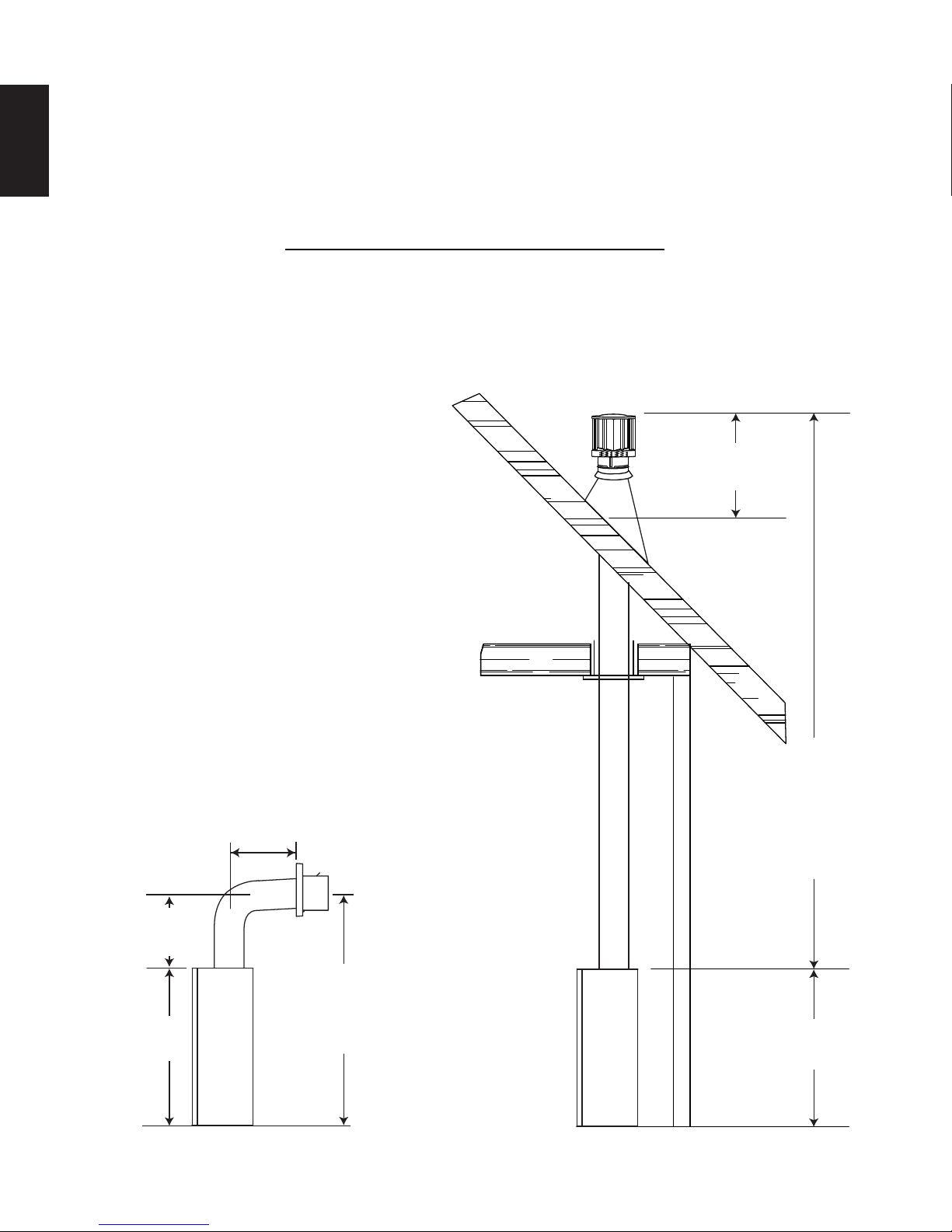
3.2 TYPICAL VENT INSTALLATIONS
it is unobstructed and undamaged.
Rigid and fl exible venting systems must not be combined. Different venting manufacturer components must not
be combined.
These vent kits allow for either horizontal or vertical venting of the appliance. The maximum allowable horizontal run is
20 feet (6.1m). The maximum allowable vertical vent length is 40 feet (12.2m). The maximum number of vent connections
is two horizontally or three vertically (excluding the appliance and the air terminal connections) when using fl exible venting.
Horizontal runs may have a 0” rise per foot however for optimum performance it is recommended that all
horizontal runs have a minimum 1/4" (6mm) rise per foot using fl exible or rigid venting. For safe and proper
operation of the appliance, follow the venting instructions exactly.
When terminating vertically, the vertical rise is a minimum 3 feet (1m) and a maximum 40 feet (12m) from the
top of the appliance.
8.1A
16" (406mm)
MIN
24" (610mm)
19 1/2" (495mm)
MIN
38"
(965mm)
* See “VENTING” section.
W415-1348 / A / 07.17.15
MAX
57 1/2"
(1461mm)
MIN PLUS
RISE*
40FT (12m)
MAX
3FT (1m)
MIN
38"
(965mm)
3.3 SPECIAL VENT INSTALLATIONS
11
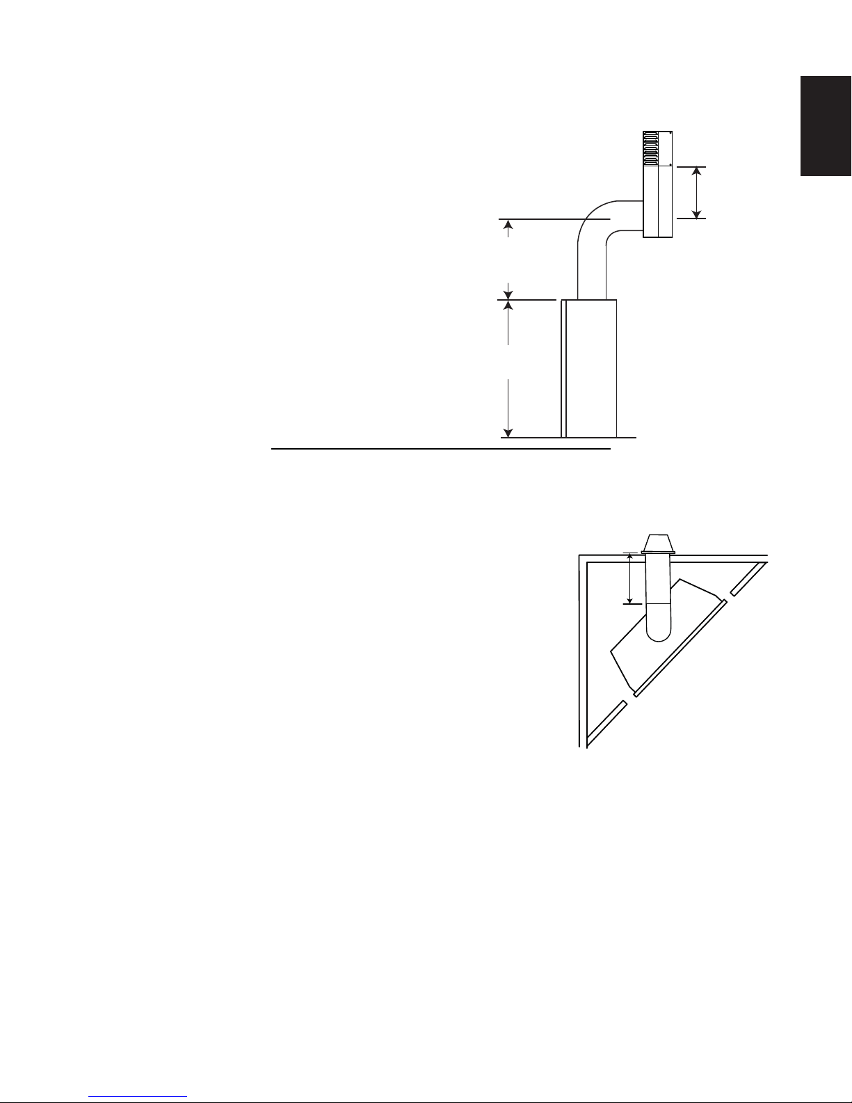
3.3.1 PERISCOPE TERMINATION
Use the periscope kit to locate the air termination above grade. The periscope must
be installed so that when fi nal grading is completed, the bottom air slot is located a
minimum 12” (305m) above grade. The maximum allowable vent length is 10’ (3m)
for a fi replace and 8’ (2m) for a stove.
3.3.2 CORNER TERMINATION
The maximum vent length for a corner installation is 81 3/4" (2076mm) of
horizontal run with a minimum 19 1/2" (495mm) rise.
EN
12" (305mm)
MIN TO
GRADE
30"
(762mm)
MIN
38"
(965mm)
9.1B
20” (508mm)
MAX
W415-1348 / A / 07.17.15
12
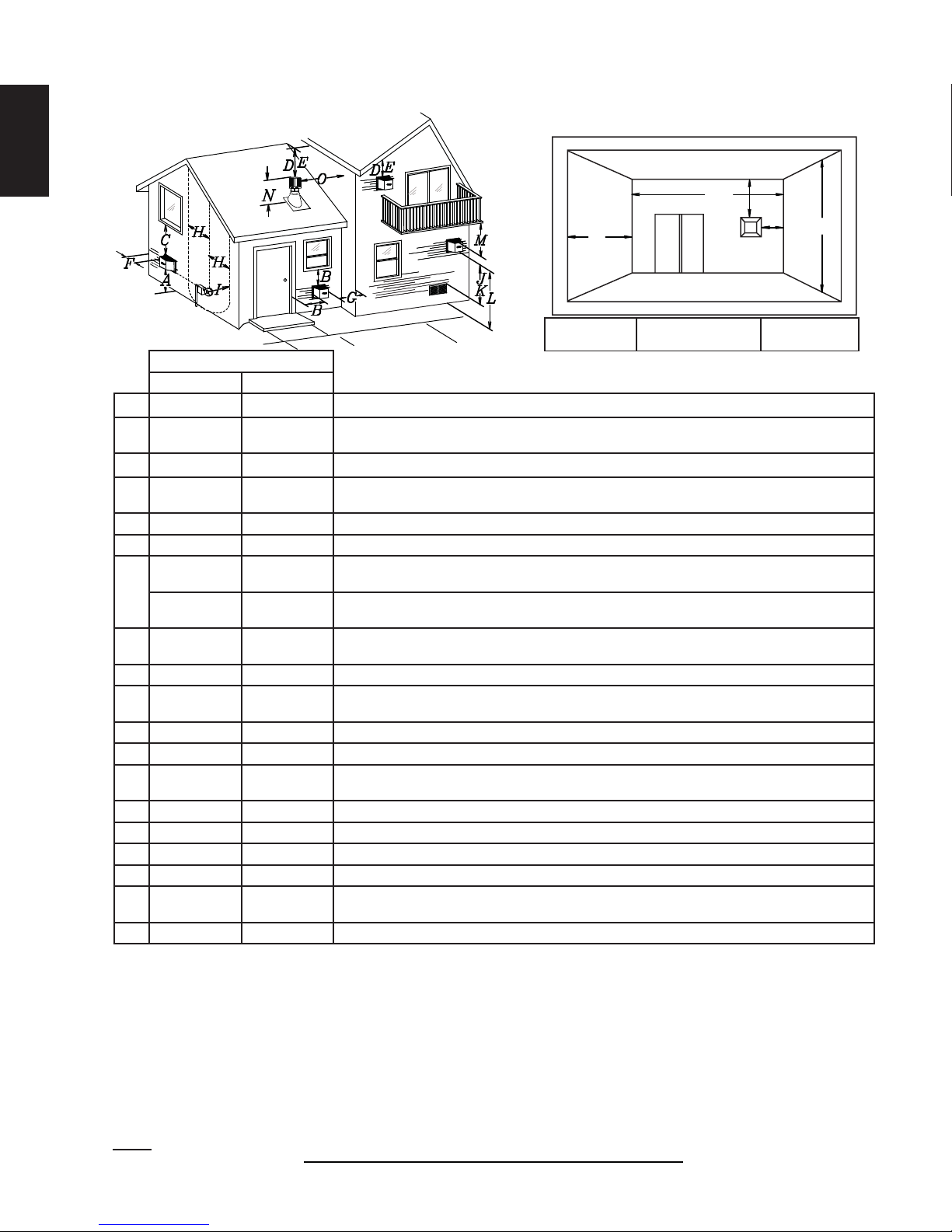
3.4 VENT TERMINAL CLEARANCES
EN
COVERED BALCONY APPLICATIONS ††*
Q
S
R
G
P
Q
= 3 feet
MIN
(0.9m)
R
MAX
INSTALLATIONS
CANADA U.S.A.
A 12” (305mm) 12” (305mm) Clearance above grade, veranda porch, deck or balcony.
B 12” (305mm)
Δ
9”
(229mm)
Clearance to windows or doors that open.
Δ
C 12” (305mm)* 12” (305mm) * Clearance to permanently closed windows.
D
18”
(457mm)**
18” (457mm)**
Vertical clearance to ventilated soffi ts located above the terminal within a horizontal distance of 2’
(0.6m) from the center line of the terminal.
E 12” (305mm)** 12” (305mm)** Clearance to unventilated soffi t.
F 0” (0mm) 0” (0mm) Clearance to an outside corner wall.
0” (0mm)***
G
2” (51mm)***
0”
(0mm)***
2”
(51mm)***
H 3’(0.9m) 3’ (0.9m)****
Clearance to an inside non-combustible corner wall or protruding non-combustible obstructions (chimney,
etc.).
Clearance to an inside combustible corner wall or protruding combustible obstructions (vent chase,
etc.).
Clearance to each side of the center line extended above the meter / regulator assembly to a
maximum vertical distance of 15’ (4.6m).
I 3’ (0.9m) 3’ (0.9m)**** Clearance to a service regulator vent outlet.
J 12” (305mm) 9” (229mm)
Clearance to a non-mechanical air supply inlet to the building or a combustion air inlet to any other
appliance.
K 6’ (1.8m) 3’ (0.9m) † Clearance to a mechanical air supply inlet.
L 7’ (2.1m) ‡ 7’ (2.1m) **** Clearance above a paved sidewalk or paved driveway located on public property.
M
12”
(305mm)††
12”
(305mm)****
Clearance under a veranda, porch or deck.
N 16” (406mm) 16” (406mm) Clearance above the roof.
O 2’ (0.6m)†* 2’ (0.6m) †* Clearance from an adjacent wall including neighbouring buildings.
P 8’ (2.4m) 8’(2.4m) Roof must be non-combustible without openings.
Q 3’ (0.9m) 3’ (0.9m) See chart for wider wall dimensions.
R 6’ (1.8m) 6’ (1.8m)
See chart for deeper wall dimensions. The terminal shall not be installed on any wall that has an
opening between the terminal and the open side of the structure.
S 12” (305mm) 12” (305mm) Clearance under a covered balcony
The terminal shall not be located less than 6 feet under a window that opens on a horizontal plane in a structure with three walls and a roof.
Δ
* Recommended to prevent condensation on windows and thermal breakage
** It is recommended to use a heat shield and to maximize the distance to vinyl clad soffi ts.
*** The periscope requires a minimum 18 inches clearance from an inside corner.
**** This is a recommended distance. For additional requirements check local codes.
† 3 feet above if within 10 feet horizontally.
‡ A vent shall not terminate where it may cause hazardous frost or ice accumulations on adjacent property surfaces.
†† Permitted only if the veranda, porch, or deck is fully open on a minimum of two sides beneath the fl oor.
†* Recommended to prevent recirculation of exhaust products. For additional requirements check local codes.
††* Permitted only if the balcony is fully open on a minimum of one side.
NOTE: Clearances are in accordance with local installation codes and the requirements of the gas supplier.
W415-1348 / A / 07.17.15
= 2 x
12.1D
Q
ACTUAL
R
MAX
IHHW
(4.6m)
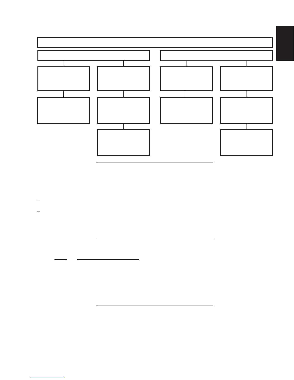
3.5 VENT APPLICATION FLOW CHART
13
Horizontal Termination
Vertical rise is equal
to or greater than
the horizontal run
Horizontal run +
vertical rise to
maximum of 40 feet
(12m)
3.6 DEFINITIONS
For the following symbols used in the venting calculations and examples are:
> - greater than
> - equal to or greater than
< - less than
< - equal to or less than
HT - total of both horizontal vent lengths (Hr) and offsets (Ho) in feet
HR - combined horizontal vent lengths in feet
HO - offset factor: .03 (total degrees of offset - 90°*) in feet
VT - combined vertical vent lengths in feet
TOP EXIT
Vertical rise is less
than horizontal run
Horizontal run +
vertical rise to
maximum of
24.75 feet (7.5m)
4.2 times the
vertical rise equal to
or greater than the
horizontal run
Vertical Termination
Vertical rise is equal
to or greater than
the horizontal run
Horizontal run +
vertical rise to
maximum of 40 feet
(12m)
EN
Vertical rise is less
than horizontal run
Horizontal run +
vertical rise to
maximum of 40 feet
(12m)
3 times the vertical
rise equal to or
greater than the
horizontal run
13.1A
14.1
3.7 ELBOW VENT LENGTHS
FEET INCHES MILLIMETERS
1° 0.03 0.5 12.7
15° 0.45 6.0 152.4
30° 0.9 11.0 279.4
45° 1.35 16.0 406.4
90°* 2.7 32.0 812.8
* The fi rst 90° offset has a zero value and is shown in the formula as - 90°
15.1A
W415-1348 / A / 07.17.15
14
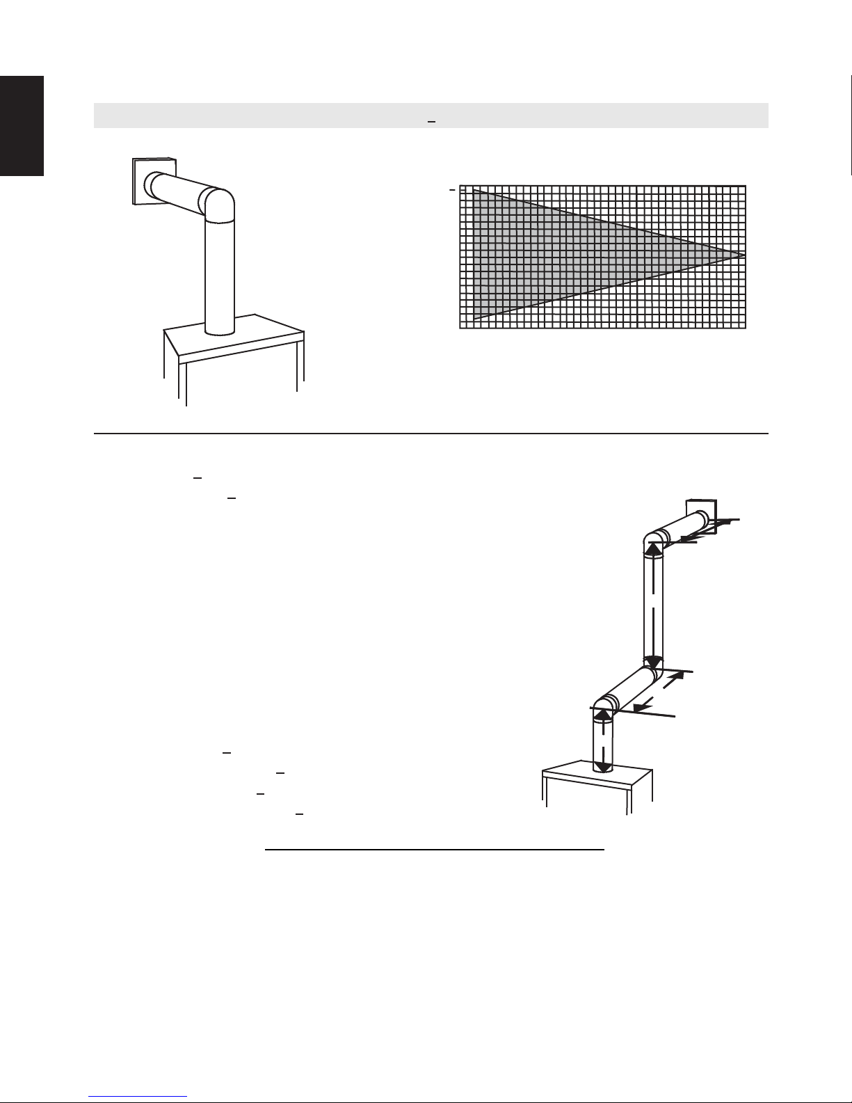
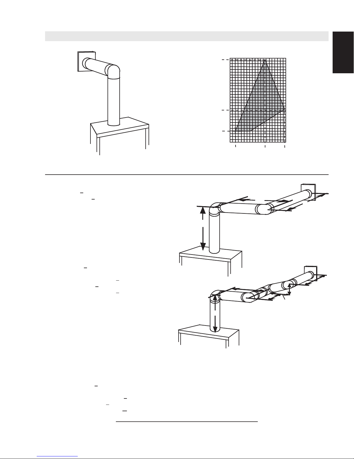
3.8 HORIZONTAL TERMINATION
EN
(HT) < (VT)
Simple venting confi guration (only one 90° elbow)
See graph to determine the required vertical
rise VT for the required horizontal run HT.
40 (12.2)
39 (11.9)
REQUIRED
30 (9.1)
VERTICAL
RISE IN FEET
20 (6.1)
(METERS)VT
10 (3.1)
0
2.5
(0.8)5(1.5)
7.5
(2.3)
10
(3.1)
12.5
(3.8)15(4.6)
HORIZONTAL VENT RUN PLUS OFFSET IN
FEET (METERS) H
T
The shaded area within the lines represents
acceptable values for HT and V
For vent confi gurations requiring more than one 90° elbow, the following formulas apply:
Formula 1: HT < V
T
Formula 2: HT + VT < 40 feet (12.2m)
17.5
(5.3)20(6.1)
T
Example:
V1 = 3 FT (0.9m)
V2 = 8 FT (2.4m)
VT = V1 + V2= 3 FT (0.9m ) + 8 FT (2.4m) = 11 FT (3.4m)
H1 = 2.5 FT (0.8m)
H2 = 2 FT (0.6m)
HR = H1 + H2 = 2.5 FT (0.8m) + 2 FT (0.6m) = 4.5 FT (1.4m)
HO = .03 (three 90° elbows - 90°) = .03 (270° - 90°) = 5.4 FT (1.7m)
HT = HR + HO = 4.5 FT (1.4m) + 5.4 FT (1.6m) = 9.9 FT (3m)
HT + VT = 9.9 FT (3m) + 11 FT (3.4m) = 20.9 FT (6.4m)
Formula 1: HT < V
T
9.9 FT (3m) < 11 FT (3.4m)
Formula 2: HT + VT < 40 FT (12.2m)
20.9 FT (6.4m) < 40 FT (12.2m)
Since both formulas are met, this vent confi guration is acceptable.
90°
V
90°
1
16.1B
90°
H
2
V
2
H
1
W415-1348 / A / 07.17.15
15
V
V
V
V
(HT) > (VT)
Simple venting configuration (only one 90° elbow)
REQUIRED
VERTICAL RISE
See graph to determine the required vertical rise VT for the
150 (3810)
(3733.8)
(3733.8)
100 (2540)
required horizontal run H
150 (3810)
147
147
100 (2540)
.
T
EN
IN INCHES
(MILLIMETERS)
V
T
HORIZONTAL VENT RUN PLUS OFFSET IN FEET (METERES) H
57 (1447.8)
57 (1447.8)
19 1/2
19 1/2
(495.3)
(495.3)
50 (1270)
50 (1270)
5
0
5
0
(1.5)
2
(1.5)
2
(0.6)
(0.6)
(3.1)
(3.1)
15
10
10
(4.6)
12.5
12.5
(3.8)
(3.8)
15
(4.6)
19.5
19.5
(5.9)
(5.9)
20 (6.1)
20 (6.1)
T
The shaded area within the lines represents acceptable
values for HT and VT
For vent configurations requiring more than one 90° elbow, the following formulas apply:
< 4.2 V
Formula 1:
Formula 2: HT + V
Example:
= VT = 6 FT (1.8m)
1
H
= 3 FT (0.9m)
1
H
= 5 FT (1.5m)
2
H
= H
R
HO = .03 (two 90° elbows - 90°) = .03 (180° - 90°) = 2.7FT (0.8m)
H
= H
T
H
+ V
T
H
T
+ H
= 3FT (0.9m) + 5FT (1.5m) = 8 FT (2.4m)
1
2
+ H
= 8FT (2.4m) + 2.7FT (0.8m) = 10.7FT (3.3m)
R
O
= 10.7FT (3.3m) + 6FT (1.8m) = 16.7FT (5.1m)
T
T
< 24.75 feet (7.5m)
T
90°
V
1
H
1
H
2
90°
Formula 1: HT < 4.2 V
4.2 VT = 4.2FT (1.3m) x 6FT (1.8m) = 25.2FT (7.7m)
10.7FT (3.3m) < 25.2FT (7.7m)
Formula 2: HT + V
16.7FT (5.1m) < 24.75 (7.5m)
Since both formulas are met, this vent configuration is acceptable.
Example:
= 4 FT (1.2m)
1
= 1.5 FT (0.5m)
2
= V
+ V
T
H
= 2 FT (0.6m)
1
H
= 1 FT (0.3m)
2
H
= 1 FT (0.3m)
3
H
= 1.5 FT (0.5m)
4
H
= H
R
H
= .03 (four 90° elbows - 90°) = .03 (360° - 90°) = 8.1 FT (2.5m)
O
H
= H
T
H
+ V
T
= 4FT (1.2m) + 1.5FT (0.5m) = 5.5 FT (1.7m)
1
2
+ H2 + H
1
+ H
= 5.5 FT (1.7m) + 8.1 FT (2.5m) = 13.6 FT (4.2m)
R
O
= 13.6 FT (4.2m) + 5.5 FT (1.7m) = 19.1 FT (5.8m)
T
Formula 1: HT < 4.2 V
4.2 VT = 4.2 FT (1.3m) x 5.5 FT(1.7m) = 23.1 FT (7m)
T
< 24.75 FT (7.5m)
T
90°
H
1
90°
V
1
+ H4 = 2FT (0.6m) + 1FT (0.3m) + 1FT (0.3m) + 1.5FT (0.5m) = 5.5 FT (1.7m)
3
T
90°
90°
H
V
2
H
H
2
3
4
13.6 FT (4.2m) < 23.1 FT (7m)
Formula 2: HT + V
19.1FT (5.8m) < 24.75 FT (7.5m)
< 24.75 FT (7.5m)
T
Since both formulas are met, this vent configuration is acceptable.
16.1_2A
W415-1348 / A / 07.17.15
16
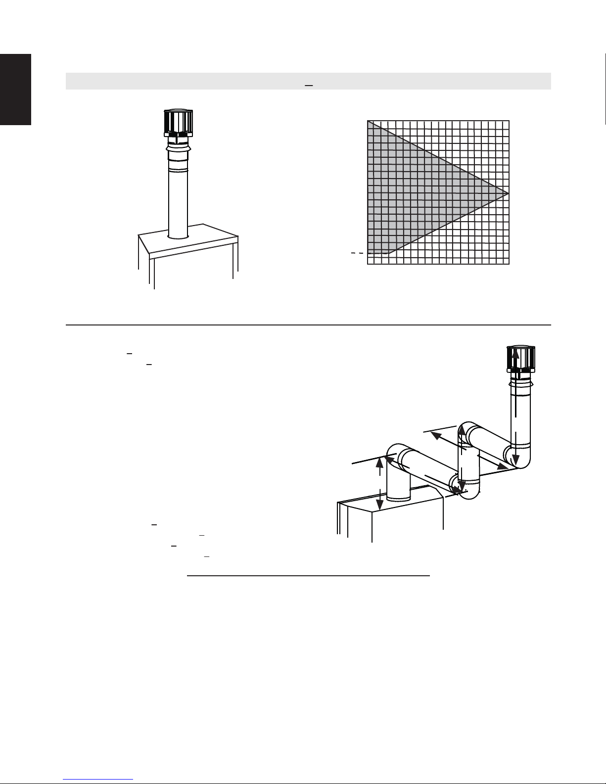
3.9 VERTICAL TERMINATION
EN
(HT) < (VT)
Simple venting configurations.
See graph to determine the required vertical rise V
required horizontal run HT.
40 (12.2)
30 (9.1)
REQUIRED
VERTICAL
RISE IN FEET
(METERS) V
T
3 (0.9)
20 (6.1)
10 (3.1)
0
5
(1.5)
HORIZONTAL VENT RUN PLUS OFFSET IN FEET (METERS) H
The shaded area within the lines represents acceptable
values for HT and VT
For vent configurations requiring one or more 90° elbows the following formulas apply:
Formula 1: H
Formula 2: HT + V
< V
T
T
< 40 feet (12.2m)
T
10
(3.1)
15
(4.6)
20
(6.1)
for the
T
T
Example:
V
= 5 FT (1.5m)
1
V
= 6 FT (1.8m)
2
V
= 10 FT (3.1m)
3
V
= V
+ V2 + V3 = 5FT (1.5m) + 6FT (1.8m) + 10FT (3.1m) = 21FT (6.4m)
T
1
H
= 8 FT (2.4m)
1
H
= 2.5 FT (0.8m)
2
H
= H
+ H
R
H
= .03 (four 90° elbows - 90°)
O
= .03 (360° - 90°) = 8.1 FT (2.5m)
H
= H
T
H
+ V
T
Formula 1: HT < V
18.6FT (5.7m) < 21FT (6.4m)
Formula 2: HT + V
39.6FT (12.1m) < 40FT (12.2m)
= 8FT (2.4m) + 2.5FT (0.8m) = 10.5 FT (3.2m)
1
2
+ H
= 10.5FT (3.2m) + 8.1FT (2.5m) = 18.6FT (5.7m)
R
O
= 18.6FT (5.7m) + 21FT (6.4m) = 39.6FT (12.1m)
T
T
< 40 FT (12.19m)
T
Since both formulas are met, this vent configuration is acceptable.
V
90°
1
90°
V
3
H
2
V
H
1
2
90°
90°
18.1A
W415-1348 / A / 07.17.15
17
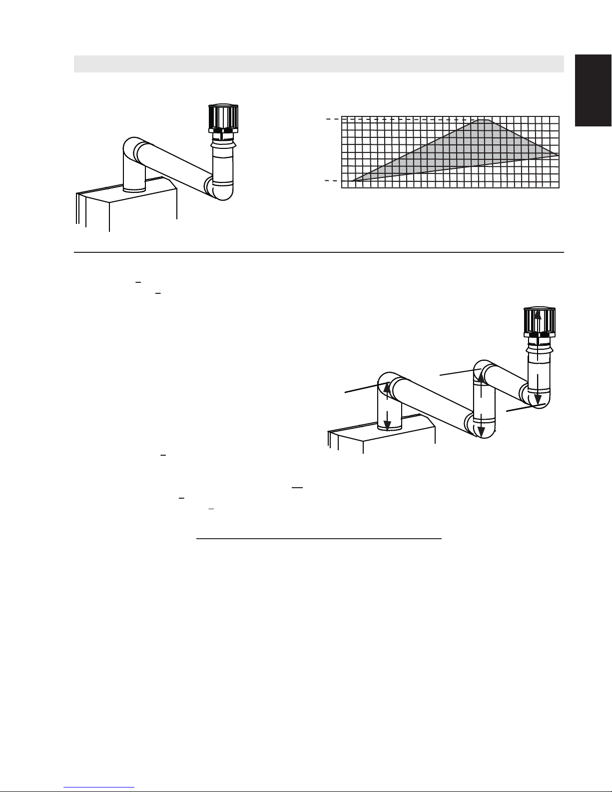
Simple venting configurations.
(HT) > (VT)
20 (6.1)
19 (5.8)
See graph to determine the required vertical rise V
required horizontal run H
.
T
for the
T
REQUIRED
VERTICAL
RISE IN FEET
(METERS) V
T
3 (0.9)
10 (3.1)
0
5
(1.5)
10
(3.1)
15
(4.6)
20
(6.1)
25
(7.6)
(9.1)
HORIZONTAL VENT RUN PLUS OFFSET IN FEET (METERS) H
The shaded area within the lines represents acceptable
values for H
and VT
T
For vent configurations requiring more than two 90° elbows the following formulas apply:
Formula 1: H
Formula 2: HT + V
< 3V
T
T
< 40 feet (12.2m)
T
Example:
V
= 2 FT (0.6m)
1
V
= 1 FT (0.3m)
2
V
= 1.5 FT (0.5m)
3
V
= V1+V2+V3= 2FT (0.6m) + 1FT (0.3m) + 1.5FT (0.5m) = 4.5FT (1.4m)
T
H
= 6 FT (1.8m)
1
H
= 2 FT (0.6m)
2
H
= H
+ H
R
H
= .03 (four 90° elbows - 90°)
O
= .03 (360° - 90°) = 8.1 FT (2.5m)
H
= H
T
H
+ V
T
= 6FT (1.8m) + 2FT (0.6m) = 8 FT (2.4m)
1
2
+ H
= 8FT (2.4m) + 8.1FT (2.5m) = 16.1FT (4.9m)
R
O
= 16.1FT (4.9m) + 4.5FT (1.4m) = 20.6 FT (6.3m)
T
90°
H
V
1
1
90°
V
H
2
V
2
3
90°
90°
Formula 1: HT < 3V
3VT = 3FT (0.9m) x 4.5FT (1.4m) = 13.5FT (4.1m)
T
16.1FT (4.9m) > 13.5FT (4.1m)
Since this formula is not met, this vent configuration is unacceptable.
Formula 2: HT + VT < 40 feet (12.2m)
20.6FT (6.3m) < 40 (12.2m)
Since only formula 2 is met, this vent configuration is unacceptable and a new appliance location or vent configuration will
need to be established to satisfy both formulas.
18.1_2B
30
T
EN
W415-1348 / A / 07.17.15
18
AIR
INTAKE
EXHAUST
FLUE
FLEX
LINER
* 40 FT (12.2m)
MAX.
10 FT (3.1m)
MIN
COAXIAL TO
CO-LINEAR
ADAPATOR
APPLIANCE
VENT ADAPTOR
TERMINATION
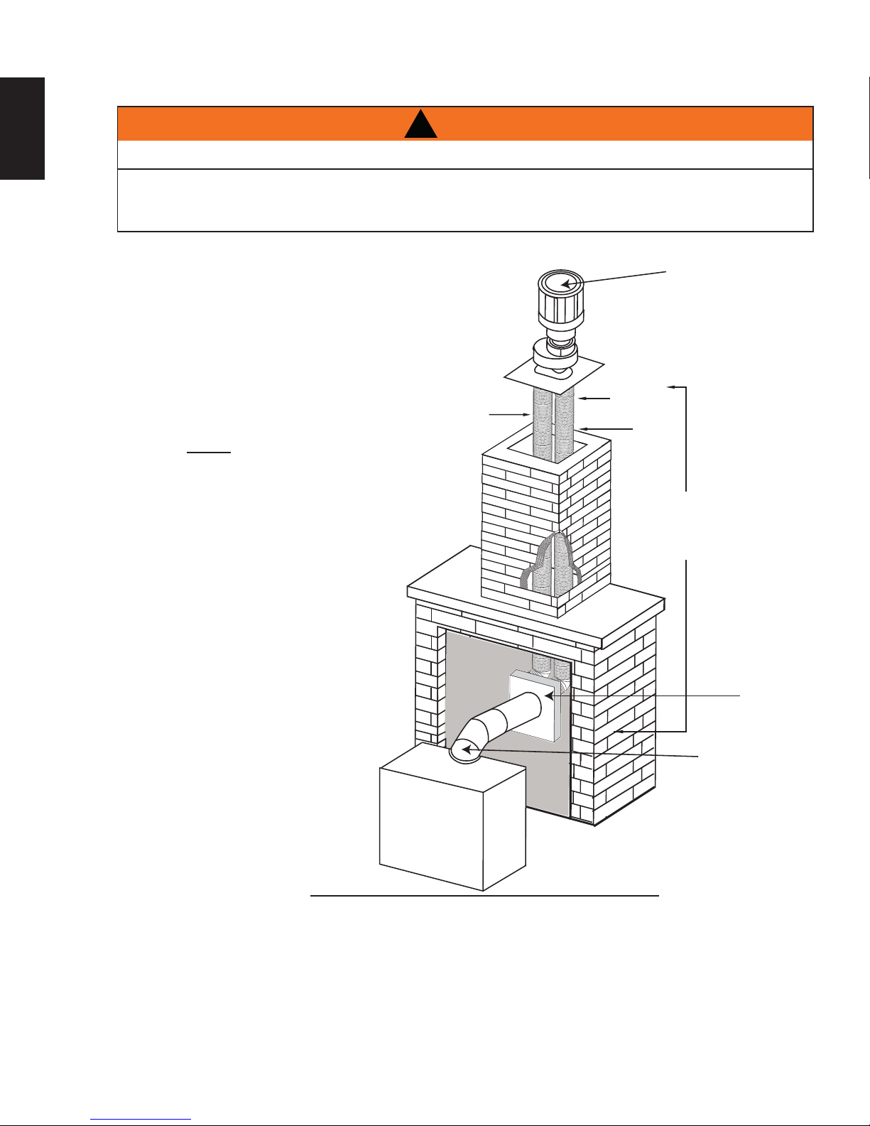
3.10 CO-AXIAL TO CO-LINEAR VENTING
EN
!
WARNING
RISK OF FIRE!
CO-AXIAL TO CO-LINEAR VENTING CONFIGURATIONS MUST ONLY BE USED IN A NON-
COMBUSTIBLE CHIMNEY OR ENCLOSURE. INSTALLATION IN A COMBUSTIBLE ENCLOSURE COULD
RESULT IN A FIRE.
This appliance is designed to be attached to a 3” (76.2mm) co-linear aluminum fl ex vent system running the
full length of a masonry chimney.
The fl ex liners accommodate any contours of a
masonry chimney, however, it is necessary to keep
the fl exible liners as straight as possible. The inlet air
collar of the termination cap must be connected to
the air intake fl ex liner and the exhaust collar must be
connected to the exhaust fl exible liner.
Both Simpson Duravent and Selkirk co-linear to
co-axial adaptors have been approved on this
appliance (NOTE: A vent adaptor will be required
directly off the appliance).
Follow vent manufacturer’s installation instructions.
Different manufacturer’s venting components must
not be combined. Once the preferred manufacturer’s
appliance adaptor has been attached, the
remainder of the system must be that of the
same manufacturer.
The only exception to this rule is to use Wolf
Steel’s approved 3” (76.2mm) fl ex liner and
co-linear termination.
* Measured from appliance fl ue collar to
termination fl ue collar
7.6A
W415-1348 / A / 07.17.15
4.0 INSTALLATION
!
WARNING
ENSURE TO UNPACK ALL LOOSE MATERIALS FROM INSIDE THE FIREBOX PRIOR TO HOOKING UP
IF YOUR APPLIANCE IS SUPPLIED WITH A REMOTE ENSURE THE REMOTE RECEIVER IS IN THE
“OFF” POSITION PRIOR TO HOOKING UP THE GAS AND ELECTRICAL SUPPLY TO THE APPLIANCE.
FOR SAFE AND PROPER OPERATION OF THE APPLIANCE, FOLLOW THE VENTING INSTRUCTIONS
ALL INNER EXHAUST AND OUTER INTAKE VENT PIPE JOINTS MAY BE SEALED USING EITHER RED
RTV HIGH TEMP SILICONE SEALANT W573-0002 (NOT SUPPLIED) OR BLACK HIGH TEMP MILL PAC
W573-0007 (NOT SUPPLIED) WITH THE EXCEPTION OF THE APPLIANCE EXHAUST FLUE COLLAR
IF USING PIPE CLAMPS TO CONNECT VENT COMPONENTS, 3 SCREWS MUST ALSO BE USED TO
RISK OF FIRE, EXPLOSION OR ASPHYXIATION. IMPROPER SUPPORT OF THE ENTIRE VENTING
SYSTEM MAY ALLOW VENT TO SAG AND SEPARATE. USE VENT RUN SUPPORTS AND CONNECT
VENT SECTIONS PER INSTALLATION INSTRUCTIONS.
THE GAS AND ELECTRICAL SUPPLY.
EXACTLY.
WHICH MUST BE SEALED USING MILL PAC.
ENSURE THE CONNECTION CANNOT SLIP OFF.
DO NOT CLAMP THE FLEXIBLE VENT PIPE.
19
EN
RISK OF FIRE, DO NOT ALLOW LOOSE MATERIALS OR INSULATION TO TOUCH THE VENT PIPE.
REMOVE INSULATION TO ALLOW FOR THE INSTALLATION OF THE ATTIC SHIELD AND TO
MAINTAIN CLEARANCES TO COMBUSTIBLES.
68.2B
4.1 WALL AND CEILING PROTECTION
!
WARNING
DO NOT FILL THE SPACE BETWEEN THE VENT PIPE AND ENCLOSURE WITH ANY TYPE OF
MATERIAL. DO NOT PACK INSULATION OR COMBUSTIBLES BETWEEN CEILING FIRESTOPS.
ALWAYS MAINTAIN SPECIFIED CLEARANCES AROUND VENTING AND FIRESTOP SYSTEMS.
INSTALL WALL SHIELDS AND FIRESTOPS AS SPECIFIED. FAILURE TO KEEP INSULATION OR
OTHER MATERIALS AWAY FROM VENT PIPE MAY CAUSE FIRE.
70.1
For optimum performance it is recommended that all horizontal runs have a minimum of 1/4' (6m) rise per foot
using fl exible venting. For safe and proper operation of the appliance, follow the venting instructions exactly.
W415-1348 / A / 07.17.15
20
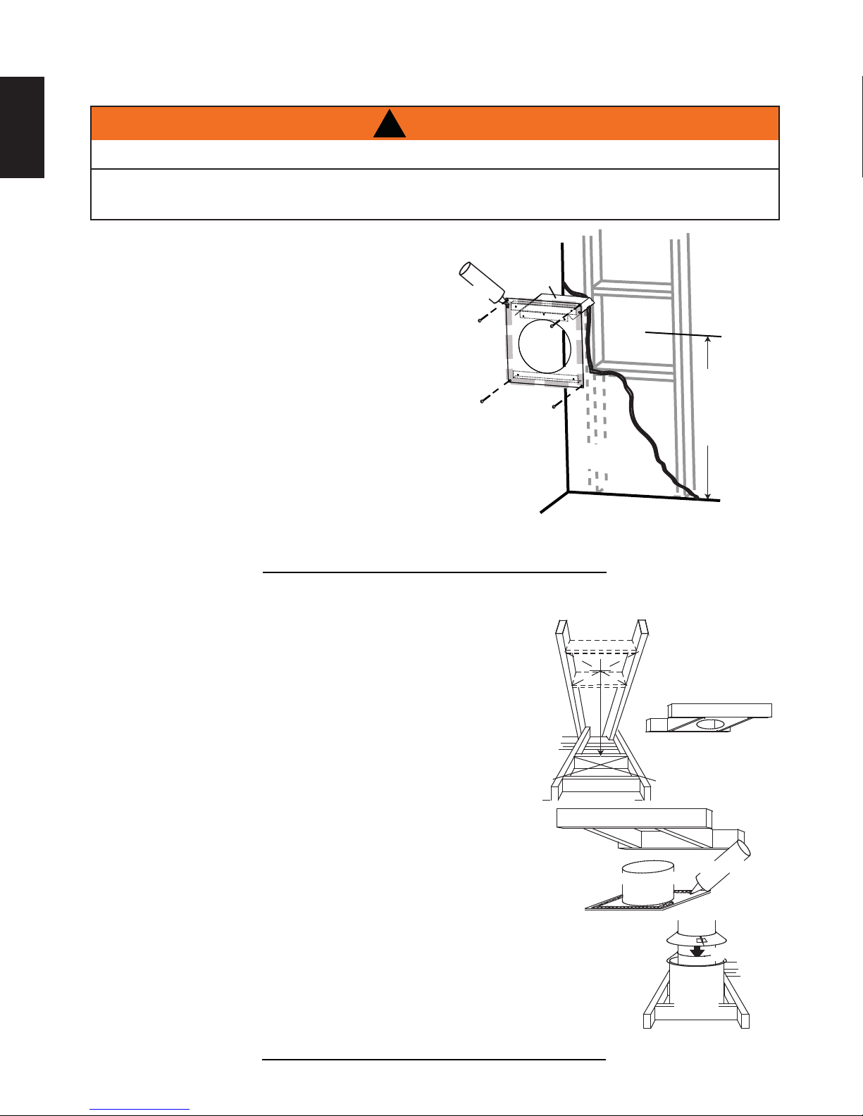
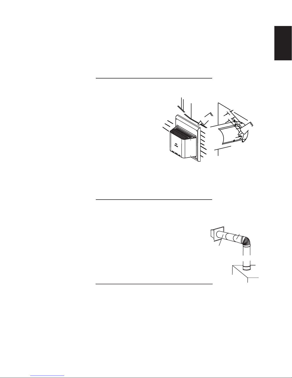
4.1.1 HORIZONTAL INSTALLATION
EN
THE FIRESTOP ASSEMBLY MUST BE INSTALLED WITH THE VENT SHIELD TO THE TOP.
TERMINALS MUST NOT BE RECESSED INTO A WALL OR SIDING MORE THAN THE DEPTH OF THE
This application occurs when venting through an exterior wall.
Having determined the correct height for the air terminal
location, cut and frame a hole in the exterior wall as
illustrated to accommodate the fi restop assembly.
Dry fi t the fi restop assembly before proceeding to
ensure the brackets on the rear surface fi t to the
inside surface of the horizontal framing.
The length of the vent shield may be cut shorter
for combustible walls that are less than 8 1/2”
(215.9mm) thick but the vent shield must extend
the full depth of the combustible wall.
A. Apply a bead of caulking (not supplied) around the corner edge of
the inside surface of the fi restop assembly, fi t the fi restop
assembly to the hole and secure using the 4 screws (supplied in your
manual baggie).
B. Once the vent pipe is installed in its fi nal position, apply high temperature sealant W573-0007 (not
supplied) between the pipe and the fi restop.
4.1.2 VERTICAL INSTALLATION
!
WARNING
RETURN FLANGE OF THE MOUNTING PLATE.
VENT
CAULKING
FIRESTOP
SPACER
SHIELD
FINISHING
MATERIAL
DETERMINE
THE
CORRECT
HEIGHT
20.2A
This application occurs when venting through a roof. Installation kits for
various roof pitches are available from your authorized dealer / distributor.
See accessories to order specifi c kits required.
A. Determine the air terminal location, cut and frame a square opening as
illustrated in the ceiling and the roof to provide the minimum 1” (25mm)
clearance between the vent pipe and any combustible material. Try to center
the vent pipe location midway between two joists to prevent having to cut
them. Use a plumb bob to line up the center of the openings. A vent pipe
shield will prevent any materials such as insulation, from fi lling up the 1”
(25mm) air space around the pipe. Nail headers between the joist for
extra support.
B. Apply a bead of caulking (not supplied) to the framework or to the Wolf
Steel vent pipe shield plate or equivalent (in the case of a fi nished ceiling),
and secure over the opening in the ceiling. A fi restop must be placed on the
bottom of each framed opening in a roof or ceiling that the venting system passes
through. Apply a bead of caulking all around and place a fi restop spacer over
the vent shield to restrict cold air from being drawn into the room or around the
fi replace. Ensure that both spacer and shield maintain the required clearance to
combustibles. Once the vent pipe is installed in its fi nal position, apply sealant between the
pipe and the fi restop assembly.
C. In the attic, slide the vent pipe collar down to cover up the open end of the shield and
tighten. This will prevent any materials, such as insulation, from fi lling up the 1” (25mm) air
space around the pipe.
W415-1348 / A / 07.17.15
9 3/4”
(248mm)
FIRESTOP
UNDERSIDE OF
JOIST
VENT PIPE
SHIELD
SHIELD
21.1
9 3/4”
(248mm)
CAULKING
VENT
PIPE
COLLAR
VENT
PIPE
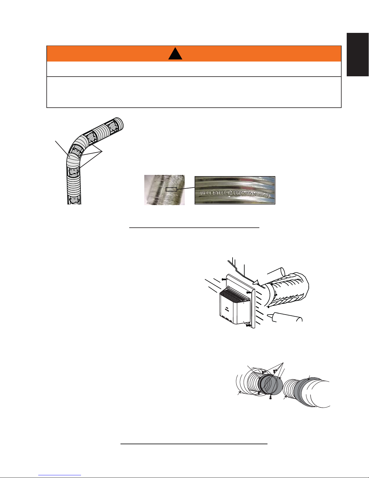
4.2 USING FLEXIBLE VENT COMPONENTS
21
!
WARNING
DO NOT ALLOW THE INNER FLEX PIPE TO BUNCH UP ON HORIZONTAL OR VERTICAL RUNS AND ELBOWS.
KEEP IT PULLED TIGHT.
SPACERS ARE ATTACHED TO THE INNER FLEX PIPE AT PREDETERMINED INTERVALS TO MAINTAIN AN EVEN
AIR GAP TO THE OUTER FLEX PIPE. THIS GAP IS REQUIRED FOR SAFE OPERATION. A SPACER IS REQUIRED
AT THE START, MIDDLE AND END OF EACH ELBOW TO ENSURE THIS GAP IS MAINTAINED. THESE SPACERS
MUST NOT BE REMOVED.
For safe and proper operation of the appliance, follow the venting
instructions exactly.
All inner fl ex pipe and outer fl ex pipe joints may be sealed using high
ELBOW
SPACERS
temperature sealant W573-0002 (not supplied) or the high temperature
sealant W573-0007 Mill Pac (not supplied). However, the high temperature
sealant W573-0007 Mill Pac (not supplied) must be used on the joint
connecting the inner fl ex pipe and the exhaust fl ue collar.
Use only approved fl exible vent pipe kits marked:
“Wolf Steel Approved Venting” as identifi ed
by the stamp only on the outer fl ex pipe.
22.1
EN
4.2.1 HORIZONTAL AIR TERMINAL INSTALLATION
A. Stretch the inner fl ex pipe to the required length taking into
account the additional length needed for the fi nished wall
surface. Apply a heavy bead of the high temperature
sealant W573-0007 Mill Pac (not supplied) to the inner
sleeve of the air terminal. Slip the vent pipe a minimum
of 2” (50.8mm) over the inner sleeve of the air terminal
and secure with 3 #8 screws.
B. Using the outer fl ex pipe, slide over the outer combustion
air sleeve of the air terminal and secure with 3 #8 screws.
Seal using high temperature sealant W573-0002 (not
supplied).
C. Insert the vent pipes through the fi restop maintaining the required
clearance to combustibles. Holding the air terminal (lettering in
an upright, readable position), secure to the exterior wall and
make weather tight by sealing with caulking (not supplied).
D. If more vent pipe needs to be used to reach the fi replace, couple
them together as illustrated. The vent system must be
supported approximately every 3 feet (0.9m) for both vertical
and horizontal runs. Use noncombustible strapping to
maintain the minimum clearance to combustibles.
SCREWS
HI-TEMP
SEALANT
FLEX PIPE
#10x2"
OUTER
CAULKING
INNER FLEX
PIPE
2" (50.8mm) OVERLAP
HIGH TEMPERATURE
#8 X 1/2” SELF DRILLING
INNER
FLEX PIPE
OUTER FLEX PIPE
SEALANT
SCREWS
INNER COUPLER
OUTER COUPLER
OUTER
FLEX PIPE
The air terminal mounting plate may be recessed into the exterior wall or siding no greater than the depth
of its return fl ange.
23.1B
W415-1348 / A / 07.17.15
22
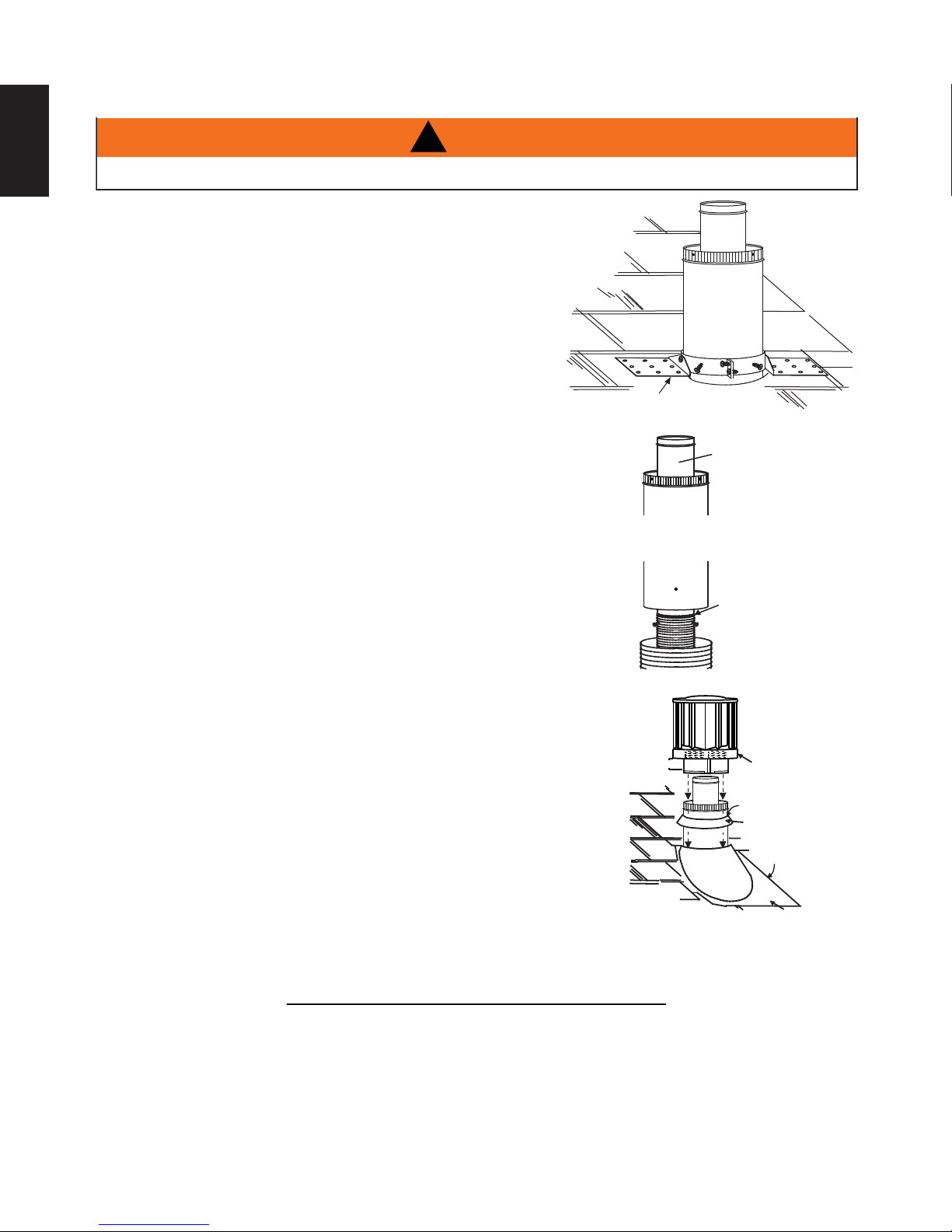
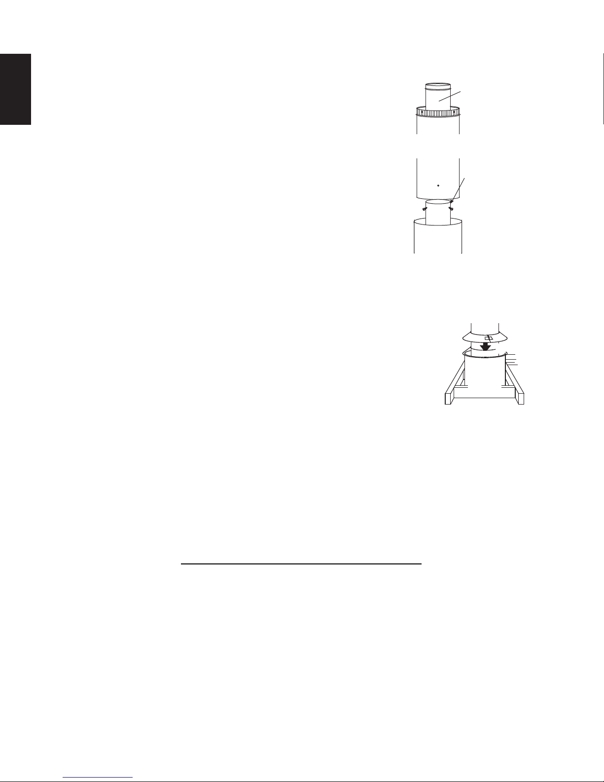
4.2.2 VERTICAL AIR TERMINAL INSTALLATION
EN
!
WARNING
MAINTAIN A MINIMUM 2” (51mm) SPACE BETWEEN THE AIR INLET BASE AND THE STORM COLLAR.
A. Fasten the roof support to the roof using the screws provided. The
roof support is optional. In this case the venting is to be adequately
supported using either an alternate method suitable to the authority
having jurisdiction or the optional roof support.
B. Stretch the inner fl ex pipe to the required length. Slip the
inner fl ex pipe a minimum of 2” (51mm) over the inner pipe
of the air terminal connector and secure with 3 #8 screws.
Seal using a heavy bead of high temperature sealant
W573-0007 (not supplied).
C. Repeat using the outer fl ex pipe, using a heavy bead of
high temperature sealant W573-0002 (not supplied).
D. Thread the air terminal connector / vent pipe assembly down through
the roof. The air terminal must be positioned vertically and plumb.
Attach the air terminal connector to the roof support, ensuring that the
top of the air terminal is 16” (406mm) above the highest point that it
penetrates the roof.
E. Remove nails from the shingles, above and to the sides of the air
terminal connector. Place the fl ashing over the air terminal connector
leaving a min. 3/4” (19mm) of the air terminal connector showing
above the top of the fl ashing. Slide the fl ashing underneath the
sides and upper edge of the shingles. Ensure that the air terminal
connector is properly centred within the fl ashing, giving a 3/4”
(19mm) margin all around. Fasten to the roof. Do not nail through
the lower portion of the fl ashing. Make weather-tight by sealing with
caulking. Where possible, cover the sides and top edges of the
fl ashing with roofi ng material.
F. Aligning the seams of the terminal and air terminal connector,
place the terminal over the air terminal connector making sure
the vent pipe goes into the hole in the terminal. Secure with
the three screws provided.
G. Apply a heavy bead of weatherproof caulking 2” (51mm) above
the fl ashing. Install the storm collar around the air terminal and
slide down to the caulking. Tighten to ensure that a weathertight seal between the air terminal and the collar is achieved.
ROOF SUPPORT
AIR
TERMINAL
CONNECTOR
2” (51mm)
INNER PIPE
HIGH
TEMPERATURE
SEALANT
INNER FLEX PIPE
OUTER FLEX PIPE
AIR I NL ET
BASE
CAULKING
STORM COLLAR
WEA THER
SEALANT
FLASHING
H. If more vent pipe needs to be used to reach the appliance see “HORIZONTAL
AIR TERMINAL INSTALLATION” section.
W415-1348 / A / 07.17.15
24.1A
4.3 USING RIGID VENT COMPONENTS
A
The vent system must be supported approximately every 3 feet (0.9m) for both vertical and horizontal runs.
Use Wolf Steel Ltd. support ring assembly or equivalent noncombustible strapping to maintain the minimum
clearance to combustibles for both vertical and horizontal runs.
ll inner exhaust and outer intake vent pipe joints may be sealed using either red high temperature silicone
sealant W573-0002 (not supplied) or black high temperature sealant W573-0007 Mill Pac (not supplied) with
the exception of the appliance exhaust fl ue collar which must be sealed using Mill Pac.
25.1A
4.3.1 HORIZONTAL AIR TERMINAL INSTALLATION
A. Move the appliance into position. Measure the
vent length required between terminal and
appliance taking into account the additional
length needed for the fi nished wall surface
and any 1¼” (31.8mm) overlaps between
venting components.
B. Apply high temperature sealant W573-0007 (not
supplied) to the outer edge of the inner exhaust fl ue
collar of the appliance. Attach the fi rst inner rigid
pipe component and secure using 3 self tapping
screws. Repeat using the outer rigid pipe.
#10x2"
SCREWS
CAULKING
OUTER
RIGID
PIPE
1" (25.4mm)
INNER
RIGID
PIPE
#8x1/2"
SELF DRILLING
SCREWS
23
EN
OVERLAP
HI-TEMP
SEALANT
C. Insert the vent pipes through the fi restop maintaining the required clearance to combustibles. Holding
the air terminal (lettering in an upright, readable position), secure to the exterior wall and make
weather tight by sealing with caulking (not supplied).
The air terminal mounting plate may be recessed into the exterior wall or siding no greater than the
depth of the return fl ange.
26.1A
4.3.2 EXTENDED HORIZONTAL AIR TERMINAL INSTALLATION
A. Follow the instructions for "HORIZONTAL AIR TERMINAL INSTALLATIONS" section.
B.
Continue adding components alternating inner rigid pipe and outer rigid pipe. Ensure
that all inner rigid pipe and elbows have sufficient vent spacers attached and each
component is sealed and securely fastened to the one prior. Attach the inner telescopic
sleeve to the vent run. Repeat using the outer telescopic sleeve. Seal and secure as
before. To facilitate completion, attach inner and outer couplers to the air terminal.
C. Install the air terminal. See “HORIZONTAL AIR TERMINAL INSTALLATION” section.
AIR TERMINAL
20" (508mm)
COUPLER
VENTING
48.1A
TELESCOPIC
SLEEVE
W415-1348 / A / 07.17.15
24
VENT
PIPE
COLLAR
VENT
PIPE
SHIELD
4.3.3 VERTICAL VENTING INSTALLATION
EN
A. Move the appliance into position.
B. Fasten the roof support to the roof using the screws provided. The
roof support is optional. In this case the venting is to be adequately
supported using either an alternate method suitable to the authority
having jurisdiction or the optional roof support.
C. Apply high temperature sealant (not supplied) to the outer edge of
the inner sleeve of the air terminal. Slip the inner coupler a minimum
of 2" (51mm)over the sleeve and secure using 3 screws.
D. Apply high temperature sealant (not supplied) to the outer edge of
the of the outside sleeve of the air terminal connector. Slip the outer
coupler over the sleeve and secure as before. Trim the outer coupler
even with the inner coupler end.
E. Thread the air terminal connector / vent pipe assembly down through
the roof support and attach, ensuring that a minimum 16" (406mm)
of air terminal connector will penetrate the roof when fastened. If
the attic space is tight, we recommend threading the Wolf Steel vent pipe collar or equivalent loosely
onto the air terminal connector / vent pipe assembly as it is passed through the attic. The air terminal
connector must be located vertically and plumb.
F. Remove nails from the shingles, above and to the sides of the air terminal
connector. Place the fl ashing over the air terminal connector and slide it
underneath the sides and upper edge of the shingles. Ensure that the air
terminal connector is properly centered within the fl ashing, giving a 3/4"
(19mm) margin all around. Fasten to the roof. Do NOT nail through the lower
portion of the fl ashing. Make weather-tight by sealing with caulking. Where
possible, cover the sides and top edges of the fl ashing with roofi ng material.
G. Apply a heavy bead of waterproof caulking 2" (51mm) above the fl ashing.
Install the storm collar around the air terminal and slide down to the caulking. Tighten to ensure that a
weather-tight seal between the air terminal connector and the collar is achieved.
H. Continue adding rigid venting sections, sealing and securing as above. Attach the inner collapsed
telescopic sleeve to the last section of rigid piping. Secure with screws and seal. Repeat using the
outer telescopic sleeve.
I. Run a bead of high temperature sealant (not supplied) around the outside of the inner exhaust fl ue
collar on the appliance. Pull the telescopic sleeve a minimum of 2" (51mm) onto the collar. Secure with
3 screws. Repeat with the outer telescopic sleeve.
J. In the attic, slide the vent pipe collar down to cover up the open end of the shield and tighten. This will
prevent any materials, such as insulation, from fi lling up the 1" (25mm) air space around the pipe.
AIR
TERMINAL
CONNECTOR
INNER PIPE
HIGH
TEMPERATURE
SEALANT
INNER RIGID
PIPE
OUTER
RIGID PIPE
W415-1348 / A / 07.17.15
27.2A
4.4 MOBILE HOME
A
25
This appliance is also certifi ed to be installed as an OEM (Original Equipment Manufacturer) installation
in a manufactured home (U.S. only) or mobile home and must be installed in accordance with the
manufacturer’s instructions and the Manufactured Home Construction and Safety Standard, Title 24 CFR,
Part 3280, in the United States or the Mobile Home Standard, CAN/CSA Z240 MH Series, in Canada. This
appliance is only for use with the type(s) of gas indicated on the rating plate.
This Mobile/Manufactured Home Listed appliance comes factory equipped with a means to secure the unit. Built
in appliances are equipped with 1/4” (6.4mm) diameter holes located in the front left and right corners of the
base. Use #10 hex head screws, inserted through the holes in the base to secure. For free standing products
contact your local authorized dealer / distributor for the appropriate securing kit. For mobile home installations, the
appliance must be fastened in place. It is recommended that the appliance be secured in all installations. Always
turn off the pilot and the fuel supply at the source, prior to moving the mobile home. After moving the mobile home
and prior to lighting the appliance, ensure that the logs are positioned correctly.
This appliance is certifi ed to be installed in an aftermarket permanently located, manufactured (mobile)
home, where not prohibited by local codes.
This appliance is only for use with the type of gas indicated on the rating plate. This appliance is not
convertible for use with other gases, unless a certifi ed kit is used.
conversion kit is supplied with the mobile home appliance.
Conversion Kits
This appliance is fi eld convertible between Natural Gas (NG) and Propane (LP).
To convert from one gas to another consult your Authorized dealer/distributor.
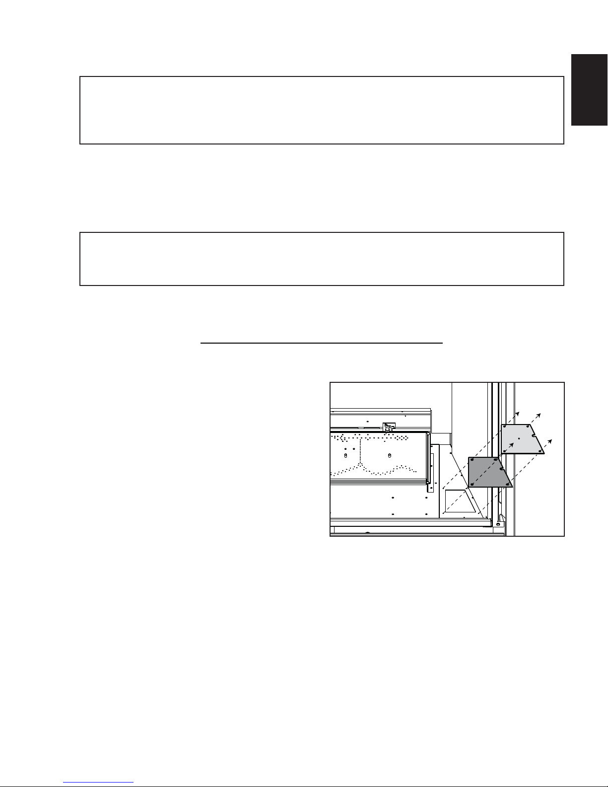
4.5 ACCESS PANEL FOR GAS LINE CONNECTION
EN
29.1A
A. Unscrew the 4 screws that hold the Access
Panel to the fi rebox.
B. Remove the Gasket (careful not to tear).
Access
Panel
Gasket
W415-1348 / A / 07.17.15
26
4.6 GAS INSTALLATION
EN
!
WARNING
RISK OF FIRE, EXPLOSION OR ASPHYXIATION. ENSURE THERE ARE NO IGNITION SOURCES SUCH AS
SUPPORT GAS CONTROL WHEN ATTACHING GAS SUPPLY PIPE TO PREVENT DAMAGING GAS LINE.
ALWAYS LIGHT THE PILOT WHETHER FOR THE FIRST TIME OR IF THE GAS SUPPLY HAS RUN OUT
WITH THE GLASS DOOR OPENED OR REMOVED. PURGING OF THE GAS SUPPLY LINE SHOULD BE
PERFORMED BY A QUALIFIED SERVICE TECHNICIAN. ASSURE THAT A CONTINUOUS GAS FLOW IS AT
THE BURNER BEFORE CLOSING THE DOOR. ENSURE ADEQUATE VENTILATION. FOR GAS AND
ELECTRICAL LOCATIONS, SEE “DIMENSION” SECTION.
ALL GAS CONNECTIONS MUST BE CONTAINED WITHIN THE APPLIANCE WHEN COMPLETE.
HIGH PRESSURE WILL DAMAGE VALVE. DISCONNECT GAS SUPPLY PIPING BEFORE TESTING GAS
LINE AT TEST PRESSURES ABOVE 1/2 PSIG.
VALVE SETTINGS HAVE BEEN FACTORY SET, DO NOT CHANGE.
Installation and servicing to be done by a qualifi ed installer. Do not use open fl ame.
• Move the appliance into position and secure.
• If equipped with a fl ex connector the appliance is designed to accept a 1/2” (13mm) gas supply.
Without the connector it is designed to accept a 3/8” (9.5mm) gas supply. The appliance is equipped
with a manual shut off valve to turn off the gas supply to the appliance.
• Connect the gas supply in accordance to local codes. In the absence of local codes, install to the
current CAN/CSA-B149.1 Installation Code in Canada or to the current National Fuel Gas Code, ANSI
Z223.1 / NFPA 54 in the United States.
• When fl exing any gas line, support the gas valve so that the lines are not bent or kinked.
• Check for gas leaks by brushing on a soap and water solution.
SPARKS OR OPEN FLAMES.
30.1A
W415-1348 / A / 07.17.15
5.0 FRAMING
27
!
WARNING
RISK OF FIRE!
IN ORDER TO AVOID THE POSSIBILITY OF EXPOSED INSULATION OR VAPOUR BARRIER COMING
IN CONTACT WITH THE APPLIANCE BODY, IT IS RECOMMENDED THAT THE WALLS OF THE
APPLIANCE ENCLOSURE BE “FINISHED” (IE: DRYWALL / SHEETROCK), AS YOU WOULD FINISH
ANY OTHER OUTSIDE WALL OF A HOME. THIS WILL ENSURE THAT CLEARANCE TO
COMBUSTIBLES IS MAINTAINED WITHIN THE CAVITY.
DO NOT NOTCH THE FRAMING AROUND THE APPLIANCE STAND-OFFS. FAILURE TO MAINTAIN
AIR SPACE CLEARANCE MAY CAUSE OVER HEATING AND FIRE. PREVENT CONTACT WITH
SAGGING OR LOOSE INSULATION OR FRAMING AND OTHER COMBUSTIBLE MATERIALS. BLOCK
OPENING INTO THE CHASE TO PREVENT ENTRY OF BLOWN-IN INSULATION. MAKE SURE
INSULATION AND OTHER MATERIALS ARE SECURED.
WHEN CONSTRUCTING THE ENCLOSURE ALLOW FOR FINISHING MATERIAL THICKNESS TO
MAINTAIN CLEARANCES. FRAMING OR FINISHING MATERIAL CLOSER THAN THE MINIMUMS
LISTED MUST BE CONSTRUCTED ENTIRELY OF NON-COMBUSTIBLE MATERIALS. MATERIALS
CONSISTING ENTIRELY OF STEEL, IRON, BRICK, TILE, CONCRETE, SLATE, GLASS OR PLASTERS,
OR ANY COMBINATION THEREOF ARE SUITABLE. MATERIALS THAT ARE REPORTED AS PASSING
ASTM E 136, STANDARD TEST METHOD FOR BEHAVIOUR OF MATERIALS IN A VERTICAL TUBE
FURNACE AT 1382° F (750°C) AND UL763 SHALL BE CONSIDERED NON-COMBUSTIBLE
MATERIALS.
MINIMUM CLEARANCE TO COMBUSTIBLES MUST BE MAINTAINED OR A SERIOUS FIRE HAZARD
COULD RESULT.
THE APPLIANCE REQUIRES A MINIMUM ENCLOSURE HEIGHT. MEASURE FROM THE APPLIANCE
BASE.
IF STEEL STUD FRAMING KITS WITH CEMENT BOARD ARE PROVIDED, OR SPECIFIED IN THE
INSTALLATION INSTRUCTIONS. THEY MUST BE INSTALLED.
FINISHING MUST BE DONE USING A NON-COMBUSTIBLE MATERIAL EXTENDING FROM THE TOP
OF THE APPLIANCE SUCH AS NON-COMBUSTIBLE BOARD, CERAMIC TILE, MARBLE, ETC. DO
NOT USE WOOD OR DRYWALL.
ANY FIRE RATED DRYWALL IS NOT ACCEPTABLE.
71.1B
EN
It is best to frame your appliance after it is positioned and the vent system is installed. Frame to local building codes.
It is not necessary to install a hearth extension with this appliance.
When roughing in the appliance, raise the appliance to accommodate for the thickness of the fi nished fl oor materials,
i.e. tile, carpeting, hard wood, which if not planned for will interfere with the opening of the lower access door and the
installation of many decorative fl ashing accessories.
Combustible materials may be installed fl ush with the front of the appliance but must not cover any of the black face-
areas of the appliance. Non-combustible material (brick, stone or ceramic tile) may protrude in these areas.
W415-1348 / A / 07.17.15
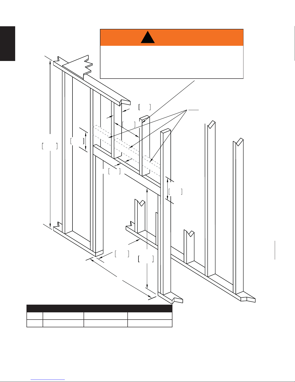
EN
DO NOT BUILD INTO THIS AREA - IT MUST BE LEFT
CLEAR TO PROVIDE ADEQUATE CLEARANCE FOR
THE VENT IN THIS 14” (356MM) WIDE AREA CENTERED
ALONG THE FRONT OF THE APPLIANCE. NO
COMBUSTIBLES ARE ALLOWED.
!
WARNING
70”
1778mm **
3 1/2”
89mm MAX
14”
356mm MIN
1 1/2”
38mm MAX
20 3/4”
527mm **
41 1/4”
1048mm **
A
NOTE: THREE BRACES ARE REQUIRED (AS
NAILERS).
4 3/4”
121mm
6 1/2”
165mm
28
* Allow for fi nished fl oor and hearth thickness when setting these dimensions.
** When constructing the enclosure allow for fi nishing material thickness to maintain clearances.
FRAMING DIMENSIONS
Ref CHD35 CHD40 CHD46
A 35 3/4” (908mm) 40 3/4” (1035mm) 46 3/4” (1187mm)
W415-1348 / A / 07.17.15
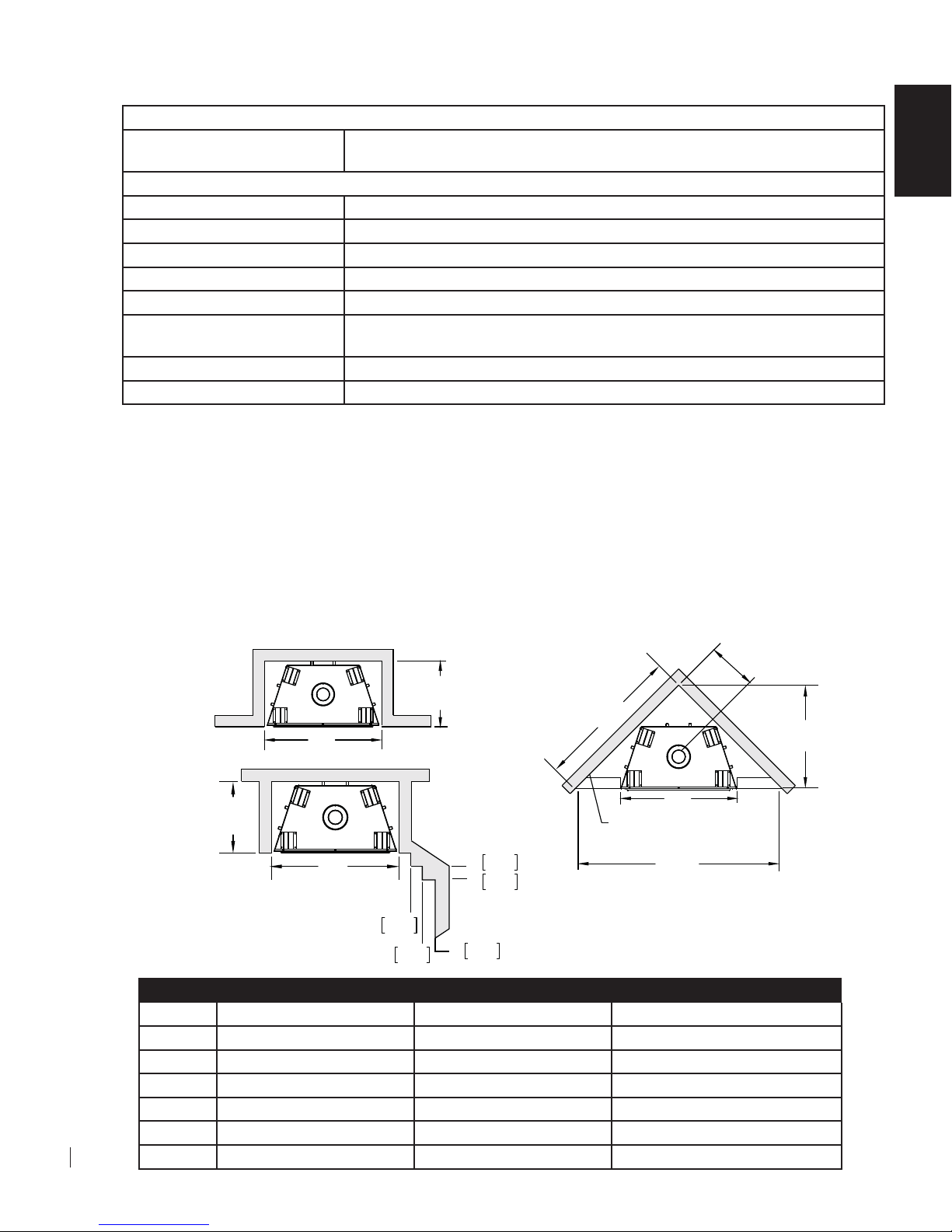
5.1 MINIMUM CLEARANCE TO COMBUSTIBLES
COMBUSTIBLE FRAMING:
Sides, back, bottom and top
of the appliance
COMBUSTIBLE FINISHING:
Bottom 0" to front edge of the appliance
Sides 1 1/4" to front edge of the appliance
Bottom 6 1/2" to front edge of the appliance
Enclosure Top 70" (1778mm) from the bottom of the appliance
Recessed Depth 20" (508mm)
Sides and bottom of the vent
pipe
Top of vent pipe 2"* (51mm)
Ceiling 62" (1575mm) from the bottom of the appliance
* HORIZONTAL VENT SECTIONS: A minimum clearance of 1" (25mm) at the bottom and sides and 2"
(51mm) at the top of the vent pipe in all horizontal runs to combustibles is required except for clearances in
appliance enclosures. Horizontal vent sections within enclosures require a minimum clearance of 9” (229mm)
at the top of the vent pipe. See “MINIMUM CLEARANCE TO COMBUSTIBLE ENCLOSURES” section. Use
fi restop spacer W010-1777 (supplied) where vent pipe penetrates combustible walls.
0" to stand-offs
1"* (25mm)
29
EN
* VERTICAL VENT SECTIONS: A minimum clearance of 1" (25mm) all around the vent pipe on all vertical
runs to combustibles is required except for clearances in appliance enclosures. Vertical vent sections
within enclosures require a minimum clearance of 4" (102mm) to the sides of the vent pipe. See “MINIMUM
CLEARANCE TO COMBUSTIBLE ENCLOSURES” section. Use fi restop spacer W500-0367 (not supplied)
where vent pipe penetrates combustible ceilings or fl oors.
D
OUTSIDE
INSIDE
CHASE
102mm
F
2"
4"
152mm
6"
51mm
102mm
C
E
A
BACK WALL OF CHASE / ENCLOSURE
(INCLUDING ANY FINSIHING MATERIALS)
B
CHASE
F
A
A
51mm
2"
4"
Ref CHD35 CHD40 CHD46
A 35 3/4" (908mm) 40 3/4" (1035mm) 46 3/4" (1187mm)
B 61 1/2" (1562mm) 66 1/2" (1689mm) 72 1/2" (1842mm)
C 43
D 14
1/2" (1105mm) 47" (1194mm) 51 1/4" (1302mm)
13/16" (376mm) 16 9/16" (421mm) 18 11/16" (475mm)
E 30 3/4" (781mm) 33 1/4" (845mm) 36 1/4" (921mm)
F 20 3/4" (527mm) 20 3/4" (527mm) 20 3/4" (527mm)
MINIMUM ENCLOSURE CLEARANCES
W415-1348 / A / 07.17.15
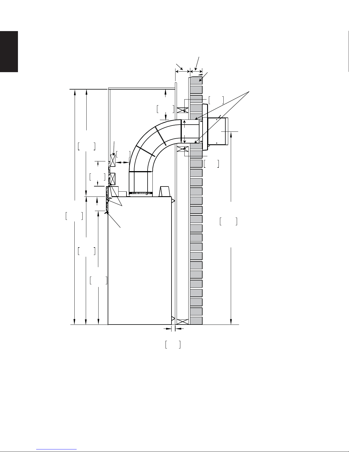
30
5.2 MINIMUM CLEARANCE TO COMBUSTIBLE ENCLOSURES
EN
32”
813mm
70”
1778mm
38”
965mm
6 1/2”
165mm
COMBUSTIBLE
9”
229mm
WOOD
HEADER
4”
102mm
NON-COMBUSTIBLE
MATERIAL
FRONT HOOD
NON-COMBUSTIBLE
BRICK
2”
51mm
1”
25mm
57 1/2”
1461mm
MINIMUM
PLUS RISE
0” IF NON-COMBUSTIBLE
FINISHING IS USED
SUCH AS BRICK AND
STONE.
33 3/4”
857mm
1”
25mm
For temperature requirements, the enclosure space around and above the appliance must be left unobstructed.
It is recommended that the enclosure be ventilated at the top and bottom to circulate the hot air.
* See “VENTING” section.
W415-1348 / A / 07.17.15
 Loading...