

Continental Fireplaces BCDV36CFGN, BCDV36CFNTR, BCDV2CFN, BCDV36CFPTR, BCDV2CFP Installation And Operating Instruction
...
1
$10.00
W415-0680 / 04.10.08
W415-0680 / 04.10.08
2
TABLE OF CONTENTS
PG 4-5 INTRODUCTION
Warranty
General Instructions
General Information
Care of Glass and Plated Parts
Unit Dimensions
Installation Overview
6-20 VENTING
Venting Lengths
Typical Minimum and Maximum Vent Lengths
Special Vent Installations
BCDV36CF(G) Periscope Termination
BCDV36CF(G) Corner Termination
BCDV42CF Periscope Termination
Venting Application Flow Chart
Defi nitions
Elbow Vent Length Values
BCDV36CF(G) Top Exit / Horizontal Termination
BCDV36CF(G) Rear Exit / Horizontal Termination
BCDV36CF(G) Top or Rear Vertical Termination
BCDV42CF Horizontal Termination
BCDV42CF Vertical Termination
BCDV36CF(G) Pre-Installation Preparation
Removing the Valve Access Door
Door Operation
Rear Exit
Top Exit
20-32 INSTALLATION
Wall and Ceiling Protection
Horizontal Installation
Adjustable Firestop Installation
Vertical Installation
Using Flexible Vent Components
Horizontal Air Terminal Installations
Vertical Air Terminal Installations
Using Rigid Vent Components
Horizontal Air Terminal Installations
Extended Horizontal and Corner Air Terminal Installations
Vertical Venting Installation
Restricting Vertical Vents (BCDV42CF ONLY)
Gas Installation
Optional wall switch installation excluding BCDV36CFG
Mobile Home Installation
Framing
Installing Standoffs
Clean Face Surround Minimum Enclosure Clearances
Optional Clean Face Surround Installation BCDV36CF(G) only
Finished Floor Installation
Hearth Installation
Minimum Air Terminal Location Clearances
BCDV36CF(G) Minimum Mantel and Enclosure Clearances
Optional Clean Face Trim Kit Installation
32 BCDV36CF FINISHING
Log Placement
Glass/Door Replacement
33-34 BCDV42CF FINISHING
Door Installation / Removal
Removing Valve Access Door
Glass/Door Replacement
Door Trim
Grate Installation
Log Placement
34-35 COMMON BCDV36CF / BCDV42CF FINISHING
Glowing Embers
Charcoal Embers
Vermiculite
Charcoal Lumps (BCDV42CF Only)
Logo Placement
35 BCDV36CFG FINISHING
Glass Burner Installation
Bulb replacement
Lens assembly replacement
36-37
BCDV42CF Accessing the Blower
Installing the Blower
37 OPTIONAL FAN INSTALLATION
GD36
38 BCDV36CFG BURNER SWITCH/WIRING
DIAGRAM
39 BCDV36CFG LIGHT SWITCH/WIRING DIAGRAM
40 RECEPTACLE WIRING DIAGRAM
40 OPERATION BCDV36CF AND BCDV42CF
BCDV42CF Minimum Mantel and Enclosure Clearances
OPTIONAL BLOWER INSTALLATION
BCDV36CF(G) Accessing the Blower
THERMOSTATIC SENSOR CONTROL
Operating Instructions
Maintenance
41 OPERATION / MAINTENANCE BCDV36CFG
42-43 ADJUSTMENTS
Pilot Burner Adjustment Excluding BCDV36CFG
Venturi Adjustment
BCDV36CFG Venturi Adjustment
Flame Adjustment
44-46 COMMON REPLACEMENTS
BCDV36CF(G) REPLACEMENTS
BCDV42CF REPLACEMENTS
46-48 TROUBLE SHOOTING GUIDE
49 SERVICE HISTORY
50-52 NOTES
!
WARNING
• Do not burn wood or other materials in this fireplace.
• Adults and especially children should be alerted to the hazards of high surface temperatures and should stay away to avoid
burns or clothing ignition. Supervise young children when they are in the same room as the fireplace.
• Clothing or other flammable material should not be placed on or near the fireplace.
• Due to high temperatures, the fireplace should be located out of traffic and away from furniture and draperies.
• Ensure you have incorporated adequate safety measure to protect infants/toddlers from touching hot surfaces.
• Even after the fireplace is out, the glass and/or screen will remain hot for an extended period of time.
• Check with your local hearth specialty dealer for safety screens and hearth guards to protect children from hot surfaces. These
screens and guards must be fastened to the floor.
• Any safety screen or guard removed for servicing must be replaced prior to operating the fireplace.
• It is imperative that the control compartments, burners and circulating blower and its passageway in the fireplace and venting
system are kept clean. The fireplace and its venting system should be inspected before use and at least annually by a qualified
service person. More frequent cleaning may be required due to excessive lint from carpeting, bedding material, etc. The fireplace
area must be kept clear and free from combustible materials, gasoline and other flammable vapours and liquids.
• Under no circumstances should this fireplace be modified.
• This fireplace must not be connected to a chimney flue pipe serving a separate solid fuel burning appliance.
• Do not use this fireplace if any part has been under water. Immediately call a qualified service technician to inspect the fireplace
and to replace any part of the control system and any gas control which has been under water.
• Do not operate the fireplace with the glass door removed, cracked or broken. Replacement of the glass should be done by a
licensed or qualified service person.
• Do not strike or slam shut the fireplace glass door.
• This fireplace uses and requires a fast acting thermocouple. Replace only with a fast acting thermocouple supplied by Wolf
Steel Ltd.
• Pressure relief doors must be kept closed while the fireplace is operating to prevent exhaust fumes containing carbon monoxide, from entering into the home. Temperatures of the exhaust escaping through these openings can also cause the surrounding
combustible materials to overheat and catch fire.
• Only doors / optional fronts certified with the unit are to be installed on the appliance.
W415-0680 / 04.10.08
NOTE: CHANGES, OTHER THAN EDITORIAL, ARE DENOTED BY A VERTICAL LINE IN THE
CONTINENTAL® products are manufactured under the strict Standard of the world recognized
ISO 9001 : 2000 Quality Assurance Certifcate.
CONTINENTAL® products are designed with superior components and materials, assembled by trained crafts-
men who take great pride in their work. The burner and valve assembly are leak and test-fired at a quality test
station. Once assembled the complete fireplace is thoroughly inspected by a qualified technician before packing to
ensure that you , the customer, receive the quality product that you expect from WOLF STEEL LTD..
3
CONTINENTAL®
GAS FIREPLACE PRESIDENT’S LIFETIME LIMITED WARRANTY
The following materials and workmanship in your new CONTINENTAL® gas fireplace are warranted against
defects for as long as you own the fireplace. This covers: combustion chamber, heat exchanger, stainless steel
burner, phazer
™ logs and embers, ceramic glass (thermal breakage only), gold plated parts against tarnishing,
porcelainized enamelled components and aluminium extrusion trims.
Electrical (110V and millivolt) components and wearable parts such as blowers, gas valves, thermal switch,
switches, wiring, remote control, igniter, gasketing, and pilot assembly are covered and WOLF STEEL LTD. will
provide replacement parts free of charge during the first year of the limited warranty.
Any labour related to warranty repair is not covered.
CONDITIONS AND LIMITATIONS
WOLF STEEL LTD. warrants its products against manufacturing defects to the original purchaser only -- i.e., the individual or legal entity
(registered customer) whose name appears on the warranty registration card filed with WOLF STEEL LTD -- provided that the purchase was
made through an authorized CONTINENTAL® dealer and is subject to the following conditions and limitations:
This factory warranty is non-transferable and may not be extended whatsoever by any of our representatives.
The gas fireplace must be installed by a licenced, authorized service technician or contractor. Installation must be done in accordance with the
installation instructions included with the product and all local and national building and fire codes.
This limited warranty does not cover damages caused by misuse, lack of maintenance, accident, alterations, abuse or neglect and parts installed
from other manufacturers will nullify this warranty.
This limited warranty further does not cover any scratches, dents, corrosion or discolouring caused by excessive heat, abrasive and chemical
cleaners nor chipping on porcelain enamel parts, mechanical breakage of PHAZER™ logs and embers.
WOLF STEEL LTD. warrants its stainless steel burners against defects in workmanship and material for life, subject to the following conditions:
During the first 10 years WOLF STEEL LTD. will replace or repair the defective parts at our option free of charge. From 10 years to life, WOLF
STEEL LTD. will provide replacement burners at 50% of the current retail price.
In the first year only, this warranty extends to the repair or replacement of warranted parts which are defective in material or workmanship
provided that the product has been operated in accordance with the operation instructions and under normal conditions.
After the first year, with respect to this President’s Limited Lifetime Warranty, WOLF STEEL LTD. may, at its discretion, fully discharge all
obligations with respect to this warranty by refunding to the original warranted purchaser the wholesale price of any warranted but defective
part(s).
WOLF STEEL LTD. will not be responsible for installation, labour or any other expenses related to the reinstallation of a warranted part and such
expenses are not covered by this warranty.
Notwithstanding any provisions contained in the President's Limited Lifetime Warranty, WOLF STEEL’S responsibility under this warranty is
defined as above and it shall not in any event extend to any incidental, consequential or indirect damages.
This warranty defines the obligations and liability of WOLF STEEL LTD. with respect to the CONTINENTAL® gas fireplace and any other
warranties expressed or implied with respect to this product, its components or accessories are excluded.
WOLF STEEL LTD. neither assumes, nor authorizes any third party to assume, on its behalf, any other liabilities with respect to the sale of this
product. WOLF STEEL LTD. will not be responsible for: over-firing, downdrafts, spillage caused by environmental conditions such as rooftops,
buildings, nearby trees, hills, mountains, inadequate vents or ventilation, excessive venting configurations, insufficient makeup air, or negative air
pressures which my or may not be caused by mechanical systems such as exhaust fans, furnaces, clothes dryers, etc.
Any damages to fireplace, combustion chamber, heat exchanger, brass trim or other components due to water, weather damage, long periods of
dampness, condensation, damaging chemicals or cleaners will not be the responsibility of WOLF STEEL LTD..
The bill of sale or copy will be required together with a serial number and a model number when making any warranty claims from your
authorized dealer. The warranyt registration card must be returned within fourteen days to register the warranty.
WOLF STEEL LTD. reserves the right to have its representative inspect any product or part thereof prior to honouring any warranty claim.
All SPECIFICATIONS AND DESIGNS ARE SUBJECT TO CHANGE WITHOUT PRIOR NOTICE DUE TO ON-GOING PRODUCT IMPROVEMENTS. CONTINENTAL® IS A REGISTERED
TRADEMARK OF WOLF STEEL LTD. PATENTS U.S. 5.303.693.801 - CAN.2.073.411, 2.082.915. © WOLF STEEL LTD.
W415-0680 / 04.10.08
4
GENERAL INSTRUCTIONS
THIS GAS FIREPLACE SHOULD BE INSTALLED AND SERVICED BY A QUALIFIED INSTALLER to conform with local codes.
Installation practices vary from region to region and it is important to know the specifi cs that apply to your area,
for example: in Massachusetts State:
• The fi replace damper must be removed or welded in the open position prior to installation of a fi replace insert or gas log.
• A carbon monoxide detector is required in all rooms containing gas fi red appliances
• The appliance off valve must be a “T” handle gas cock.
• The fl exible connector must not be longer than 36".
• The appliance is not approved for installation in a bedroom or bathroom unless the unit is a direct vent sealed combustion
product.
• WARNING: This product must be installed by a licensed plumber or gas fi tter when installed within the commonwealth of
Massachusetts.
In absence of local codes, install the BCDV36CF(G) and BCDV42CF to the current National Fuel Gas Code, ANSI Z223.1, or the
current CAN/CGA B149, Installation Codes. Mobile home installation must conform with local codes or in the absence of local
codes, install to the current standard for gas equipped mobile housing CAN/CSA ZA240 MH Series in Canada or the Manufactured Home Construction and Safety Standard, Title 24 CFR, Part 3280, or the Fire Safety Criteria for Manufactured Home
Installations, Sites and Communities Standard ANSI/NFPA 501A in the United States.
The fi replace and its individual shut off valve must be disconnected from the gas supply piping system during any pressure testing
of that system at test pressures in excess of 1/2 psig (3.5 kPa). The fi replace must be isolated from the gas supply piping system
by closing its individual manual shut off valve during any pressure testing of the gas supply piping system at test pressures equal
to or less than 1/2 psig (3.5 kPa).
When the fi replace is installed directly on carpeting, vinyl tile or other combustible material other than wood fl ooring, the fi replace shall be installed on a metal or wood panel extending the full width and depth.
If the optional fan or blower is installed, the junction box must be electrically connected and grounded in accordance with local
codes. In the absence of local codes, use the current CSA C22.1 CANADIAN ELECTRICAL CODE in Canada or the ANSI/
NFPA 70 NATIONAL ELECTRICAL CODE in the United States.
All sections with BCDV36CF(G) are common to both the BCDV36CF and the BCDV36CFG.
GENERAL INFORMATION
FOR YOUR SATISFACTION, THIS FIREPLACE HAS BEEN TEST-FIRED TO ASSURE ITS OPERATION AND QUALITY!
BCDV36CF(G) -Maximum input for the BCDV36CF(G) is 17,000 BTU/h for natural gas and propane. Maximum output for
natural gas and propane is 10,900 BTU/hr at an effi ciency of 64% with the fan on. The A.F.U.E. (annual fuel utilization effi ciency) rating is 53% for natural gas and propane.
BCDV42CF - Maximum input for the BCDV42CF is 24,000 BTU/hr for natural gas and propane. Maximum output for natural
gas and propane is 16,000 BTU/hr at an effi ciency of 67% with the fan on. The A.F.U.E. (annual fuel utilization effi ciency) rating
is 61.5% for natural gas and propane.
When the fi replace is installed at elevations above 4,500ft, and in the absence of specifi c recommendations from the local authority having jurisdiction, the certifi ed high altitude input rating shall be reduced at the rate of 4% for each additional 1,000ft.
Minimum inlet gas supply pressure is 4.5" water column for natural gas and 11" water column for propane.
Maximum inlet gas pressure is 7" water column for natural gas and 13"
water column for propane. Manifold pressure under fl ow conditions is 3.5"
water column for natural gas and 10" water column for propane.
This fi replace is approved for bathroom, bedroom and bed-sitting room
installations and is suitable for mobile home installation.
No external electricity (110 volts or 24 volts) is required for the gas
system operation.
Expansion / contraction noises during heating up and cooling down
cycles are normal and are to be expected.
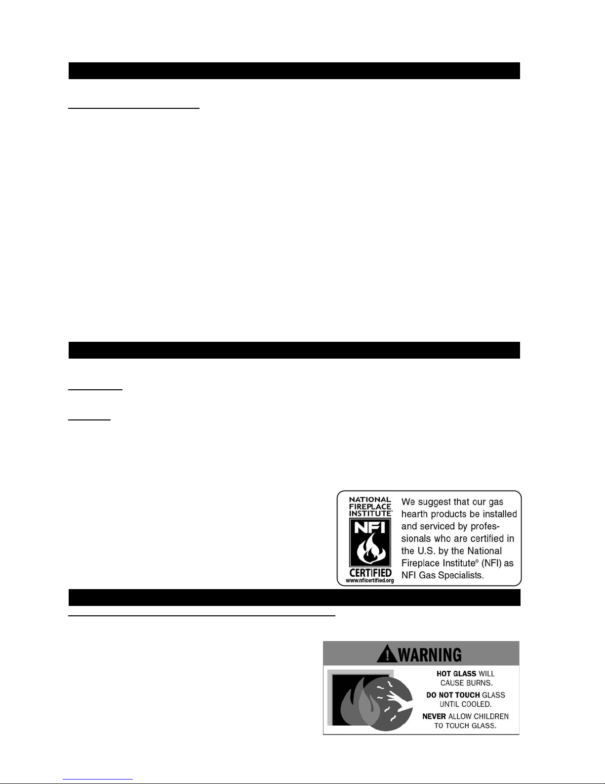
CARE OF GLASS AND PLATED PARTS
Use only accessories designed for and listed with your specifi c fi replace.
Provide adequate ventilation air. Provide adequate accessibility clearance for servicing and operating the fi replace. Never
obstruct the front opening of the fi replace. Objects placed in front of the fi replace must be kept a minimum of 48" away
from the front face of the unit.
Do not use abrasive cleaners to clean plated parts. Buff lightly with a clean
dry cloth. The BCDV36CF(G) and BCDV42CF are factory equipped
with tempered glass. The glass thickness is 3/16" for both models. Use
only replacement glass available from your Authorized dealer. DO NOT
SUBSTITUTE MATERIALS. Clean the glass after the fi rst 10 hours of operation with a recommended gas fi replace glass cleaner. Thereafter clean
as required. DO NOT CLEAN GLASS WHEN HOT! If the glass is not kept
clean permanent discoloration and / or blemishes may result.
W415-0680 / 04.10.08
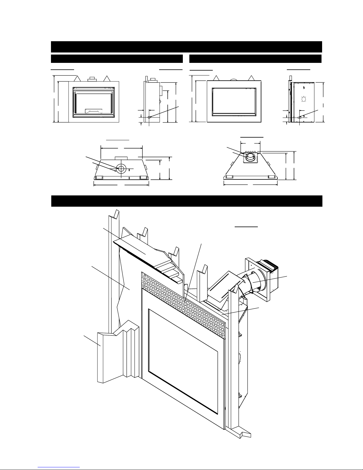
FIGURE 1
UNIT DIMENSIONS
BCDV36CF(G) BCDV42CF
FIGURE 2
FIGURE 4
5
FIGURE 5
381/2"
34"
4" DIA.
7" DIA.
See the section “MINIMUM
MANTEL AND ENCLOSURE
CLEARANCES”
See the sections “MINIMUM ENCLOSURE
CLEARANCES” for drywall
(or other combustible
material)
411/2"
33"
1
24
/4"
GAS
INLET
37"
FIGURE 3
1
/2"
5
3"
ELECTRICAL INLET
LEFT SIDE
27"
17"
15"
10"
40"
INSTALLATION OVERVIEW
See the sections “MINIMUM
ENCLOSURE CLEARANCES” for noncombustible material
5" DIA.
8" DIA.
FIGURE 6
201/2"
46"
FIGURE 7
51/2"
3"
ELECTRICAL INLET
LEFT SIDE
23"
25"
See the section
“VENTING” and
“INSTALLATION”
35 1/2"
GAS
INLET
See the section
“FRAMING”
Side Wall
See the section
“INSTALLATION-FRAMING”
BCDV42CF Illustrated
W415-0680 / 04.10.08

6
VENTING
THE BCDV36CF(G) USES: 4" EXHAUST / 7" AIR INTAKE VENT PIPE
MODEL BCDV36CF MAY BE VENTED EITHER AS A TOP VENT OR A REAR VENT.
For safe and proper operation of the fi replace follow the venting instruction exactly. Deviation from the minimum vertical
vent length can create diffi culty in burner start-up and/or carboning. Provide a means for visually checking the vent connection to the fi replace after the fi replace is installed. Vent lengths that pass through unheated spaces (attics, garages,
crawl spaces) should be insulated with the insulation wrapped in a protective sleeve to minimize condensation.
Use only Wolf Steel, Simpson Dura-Vent, Selkirk Direct Temp or American Metal Amerivent venting components. Minimum and maximum
vent lengths, for both horizontal and vertical installations, and air terminal locations for either system are set out in this manual and must be
adhered to. For Simpson Dura-Vent, Selkirk Direct Temp and American Metal Amerivent, follow the installation procedure provided with the
venting components.
A starter adaptor must be used with the following vent systems and may be purchased from the corresponding supplier:
PART 4"/7" 5"/8" SUPPLIER
Duravent W175-0053 W175-0170 Wolf Steel
Amerivent 4DSC-N2 5DSC-N American Metal
Direct Temp 4DT-AAN 5DT-AA Selkirk
For Simpson Dura-Vent, Selkirk Direct Temp and American Metal Amerivent, follow the installation procedure found on the website for your
venting supplier.
VENTING SUPPLIER WEBSITE
Simpson Dura-Vent www.duravent.com
Selkirk Direct Temp www.selkirkcorp.com
American Metal Amerivent www.americanmetalproducts.com
For vent systems that provide seals on the inner exhaust fl ue, only the outer air intake joints must be sealed using a red high temperature silicone
(RTV). This same sealant may be used on both the inner exhaust and outer intake vent pipe joints of all other approved vent systems except
for the exhaust vent pipe connection to the fi replace fl ue collar which must be sealed using the black high temperature sealant Mill Pac.
BCDV36CF(G)
When using Wolf Steel venting components, use only approved Wolf Steel rigid / fl exible components with the following termination kits: WALL
TERMINAL KIT GD222, or 1/12 to 7/12 PITCH ROOF TERMINAL KIT GD110, 8/12 to 12/12 ROOF TERMINAL KIT GD111 , FLAT ROOF
TERMINAL KIT GD112 or PERISCOPE KIT GD201 (for wall penetration below grade). With fl exible venting, in conjunction with the various
terminations, use either the 5 FOOT VENT KIT GD220 or the 10 FOOT VENT KIT GD330.
THE BCDV42CF USES: 5" EXHAUST / 8" AIR INTAKE VENT PIPE
REFER TO THE SECTION APPLICABLE TO YOUR INSTALLATION.
VENTING LENGTHS
BCDV42CF
When using Wolf Steel venting components, use only approved Wolf Steel fl exible components with the following termination kits: WALL
TERMINAL KIT GD422, or 1/12 to 7/12 PITCH ROOF TERMINAL KIT GD410, 8/12 to 12/12 ROOF TERMINAL KIT GD411, FLAT ROOF
TERMINAL KIT GD412 or PERISCOPE KIT GD401 (for wall penetration below grade). With fl exible venting, in conjunction with the various
terminations, use either the 5 FOOT VENT KIT GD420 or the 10 FOOT VENT KIT GD430.
Wolf Steel, Simpson Dura-Vent, Selkirk Direct Temp or American Metal Amerivent venting systems must not be combined. Wolf
Steel rigid and fl exible venting systems must not be combined.
These vent kits allow for either horizontal or vertical venting of the fi replace. The maximum allowable horizontal run is 20 feet. The
maximum allowable vertical vent length is 40 feet. The maximum number of vent connections is two horizontally or three vertically
(excluding the fi replace and the air terminal connections) when using fl exible venting.
For optimum fl ame appearance and fi replace performance, keep the vent length and number of elbows to a minimum.
REQUIRED RISE ON HORIZONTAL VENTING
0"
6"
BCDV42CF
0" / FT
0" / FT
0" / FT
0" / FT
0"
0"
REAR VENT
TOP VENT
CORNER
RIGID VENTING
FLEXIBLE
VENTING
RIGID VENTING
FLEXIBLE
VENTING
RIGID VENTING
FLEXIBLE
VENTING
BCDV36CF(G)
0" / FT
0" / FT
0" / FT
0" / FT
For optimum performance, it is recommended that all horizontal runs have a 1" rise per foot.
BCDV36CF(G)
HORIZONTAL VENT SECTIONS: - A minimum clearance
of 1" at the bottom and sides of the vent and 2" at the top on
all horizontal runs to combustibles is required. The fi restop
spacer (W010-1774) supplied with the unit must be used to
maintain this clearance.
VERTICAL VENT SECTIONS: - A minimum of 1" all around
the vent pipe on all vertical runs to combustibles is required
except for clearances in fi replace enclosures. See "MINIMUM
ENCLOSURE CLEARANCES" section. Use fi restop spacer
W500-0096 (not supplied).
BCDV42CF
HORIZONTAL VENT SECTIONS: A minimum clearance of 2"
all around the vent pipe on all horizontal runs to combustibles
is required. Use fi restop spacer W010-1778 (supplied).
VERTICAL VENT SECTIONS: A minimum of 1" all around the
vent pipe on all vertical runs to combustibles is required. Use
fi restop spacer W500-0028 (not supplied).
W415-0680 / 04.10.08

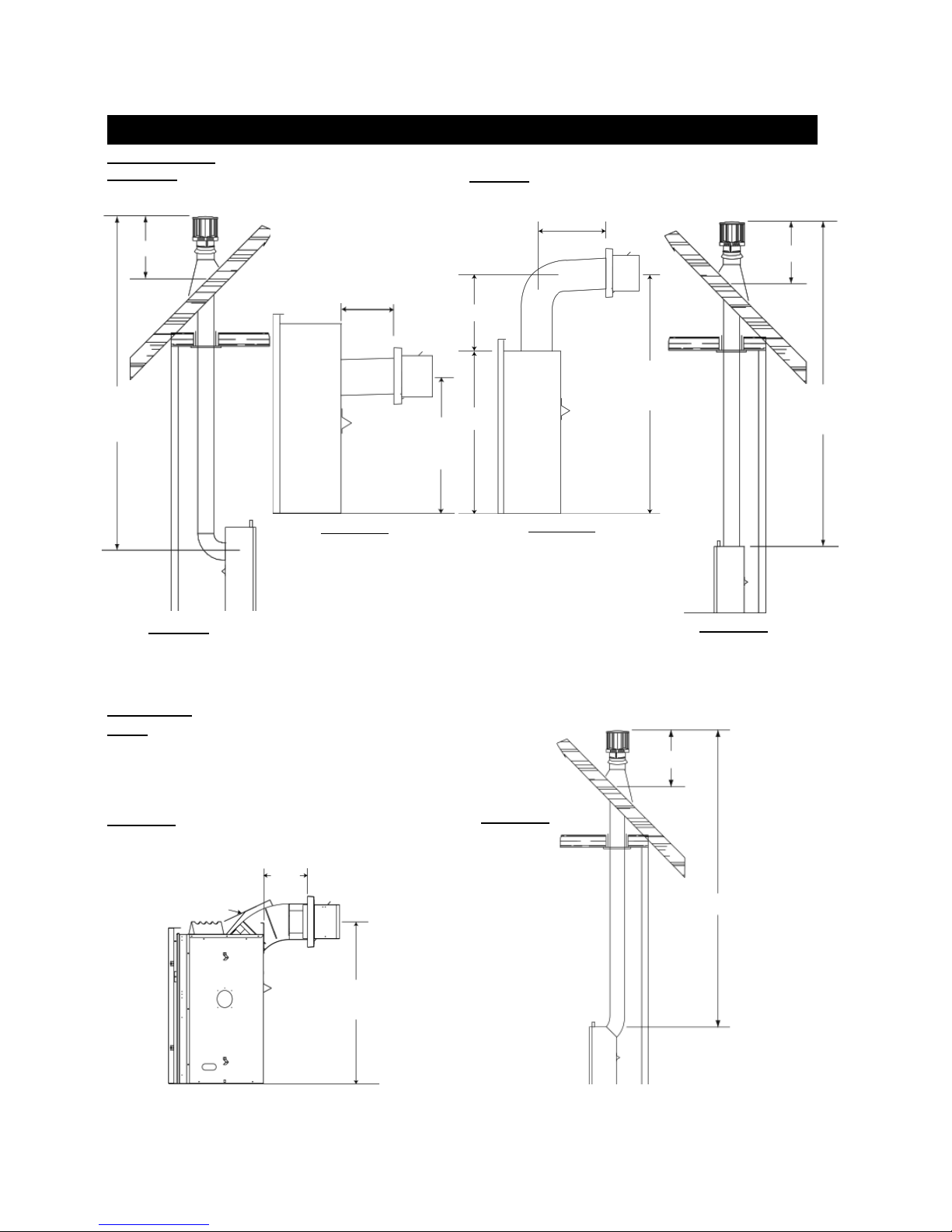
FIGURE 8
7
W415-0680 / 04.10.08
8
BCDV36CF(G)
REAR EXIT
16" MINIMUM
TYPICAL MINIMUM AND MAXIMUM VENT LENGTHS
TOP EXIT
24" MAX
16" MINIMUM
40 FT
MAX
3 FT
MIN
20" MAX
MINIMUM
24 1/2"
PLUS
RISE*
10" MIN
33"
FIGURE 10
For optimum performance, it is recommended that all horizontal
runs have a 1" rise per foot.
FIGURE 9
When terminating vertically, the vertical rise is a minimum 3
feet and a maximum 40 feet from the centre of the fi replace
fl ue outlet.
BCDV42CF
NOTE: When terminating vertically, the restrictor plate W500-0205
must be installed. Refer to Restricting Vertical Vents.
FIGURE 11
43"
MINIMUM
PLUS
RISE*
16" MINIMUM
FIGURE 12
40 FT
MAX
3 FT
MIN
FIGURE 13
18"
MAX
VENT SHIELD
* See Venting Section
W415-0680 / 04.10.08
38 1/2"
MINIMUM
PLUS RISE*
FIGURE 14
40 FT MAX
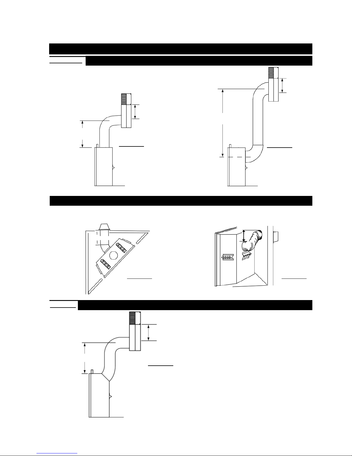
SPECIAL VENT INSTALLATIONS
9
BCDV36CF(G)
PERISCOPE TERMINATION
Use the GD201 periscope kit to locate the air termination above grade. The periscope must be
installed so that when fi nal grading is completed, the bottom air slot is located a minimum of 12"
above grade. The maximum allowable vent length is 10'.
12" MIN
TO GRADE
30"
MINIMUM
FIGURE 15
30"
MINIMUM
REAR EXIT INSTALLATIONTOP EXIT INSTALLATION
FIGURE 16
12" MIN
TO GRADE
CORNER TERMINATION
The maximum vent length for a corner installation is 20" of horizontal run, in addition to the 45° offset. In this case zero rise
is acceptable when using rigid. See FIGURE 18. Flexible venting must maintain a 6" rise. See FIGURE 19.
6" RISE
BCDV42CF
20" MAX
24" MINIMUM
FIGURE 18 FIGURE 19
CORNER INSTALLATION
PERISCOPE TERMINATION
Use the GD401 periscope kit to locate the air termination above
grade. The periscope must be installed so that when fi nal grad-
12" MIN
TO GRADE
FIGURE 17
ing is completed, the bottom air slot is located a minimum of 12"
above grade. The maximum allowable vent length is 10'.
W415-0680 / 04.10.08
10
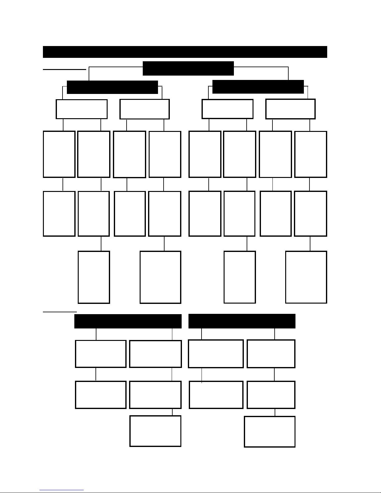
VENTING APPLICATION FLOW CHART
BCDV36CF(G)
Horizontal
Termination
Vertical
rise is
equal to
or greater
than the
horizontal
run
Horizontal run +
vertical
rise to
maximum
of 40 feet
REAR EXIT
Vertical
rise is
less than
horizontal
run
Horizontal
run + vertical rise to
maximum
of 24.75
feet
Vertical
Termination
Vertical
rise is
equal to
or greater
than the
horizontal
run
Horizontal run +
vertical
rise to
maximum
of 40 feet
FIREPLACE VENT EXIT
Horizontal
Termination
Vertical
rise is
less than
horizontal
run
Horizontal run +
vertical
rise to
maximum
of 40 feet
3 times
Vertical
rise is
equal to
or greater
than the
horizontal
run
Horizon-
tal run +
vertical
rise to
maximum
of 40 feet
TOP EXIT
Vertical
rise is
less than
horizontal
run
Horizontal
run + vertical rise to
maximum
of 24.75
feet
Vertical
Termination
Vertical
rise is
equal to
or greater
than the
horizontal
run
Horizontal run +
vertical
rise to
maximum
of 40 feet
Vertical
rise is
less than
horizontal
run
Horizon-
tal run +
vertical
rise to
maximum
of 40 feet
BCDV42CF
3.5 times
the verti-
cal rise
equal to
or greater
than the
horizontal
run
The
vertical rise
equal to or
greater than
the horizontal
run
HORIZONTAL TERMINATION
Vertical rise is
equal to or greater
than the horizontal
run
Horizontal run
+ vertical rise to
maximum of 40
feet
Vertical rise is less
than horizontal run
Horizontal run +
vertical rise to maximum of 24.75 feet
4.2 times the vertical rise equal to or
greater than the
horizontal run
4.2 times
the verti-
cal rise
equal to
or greater
than the
horizontal
run
VERTICAL TERMINATION
Vertical rise is equal
to or greater than
the horizontal run
Horizontal run
+ vertical rise to
maximum of 40
feet
Vertical rise is
less than hori-
zontal run
Horizontal run
+ vertical rise to
maximum of 40
feet
3 times The
vertical rise equal
to or greater than
the horizontal run
3 times The
vertical rise
equal to or
greater than
the horizontal
run
W415-0680 / 04.10.08
DEFINITIONS
for the following symbols used in the venting calculations and examples are:
> - greater than
> - equal to or greater than
< - less than
< - equal to or less than
- total of both horizontal vent lengths (HR) and offsets (HO) in feet
H
T
- combined horizontal vent lengths in feet
H
R
- offset factor: .03 (total degrees of offset - 90°*) in feet
H
O
- combined vertical vent lengths in feet
V
T
ELBOW VENT LENGTH VALUES
feet inches
1° 0.03 0.5
15° 0.45 6.0
30° 0.9 11.0
45°* 1.35 16.0
90°* 2.7 32.0
* BCDV36CF the fi rst 90° offset has a zero value and is shown in the formula as - 90°
* BCDV42CF the fi rst 45° and 90° offset has a zero value and is shown in the formula as -45° and - 90° respectively or -135° combined.
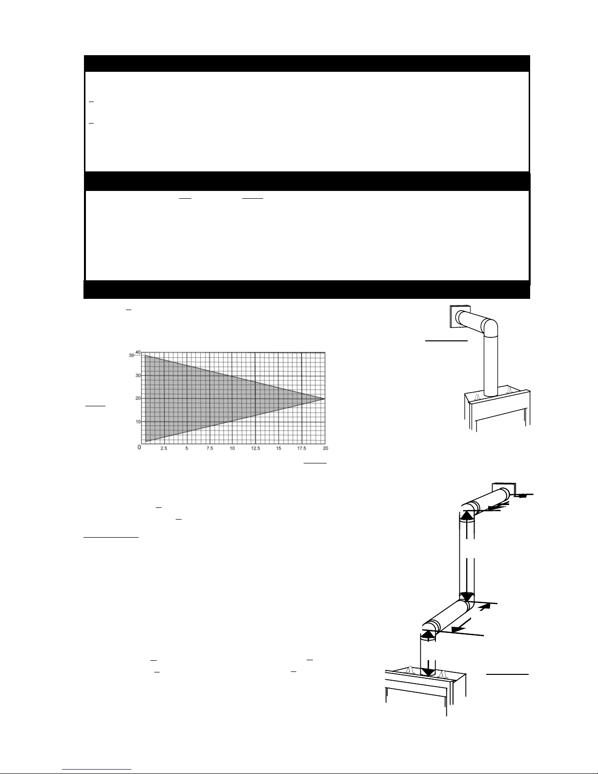
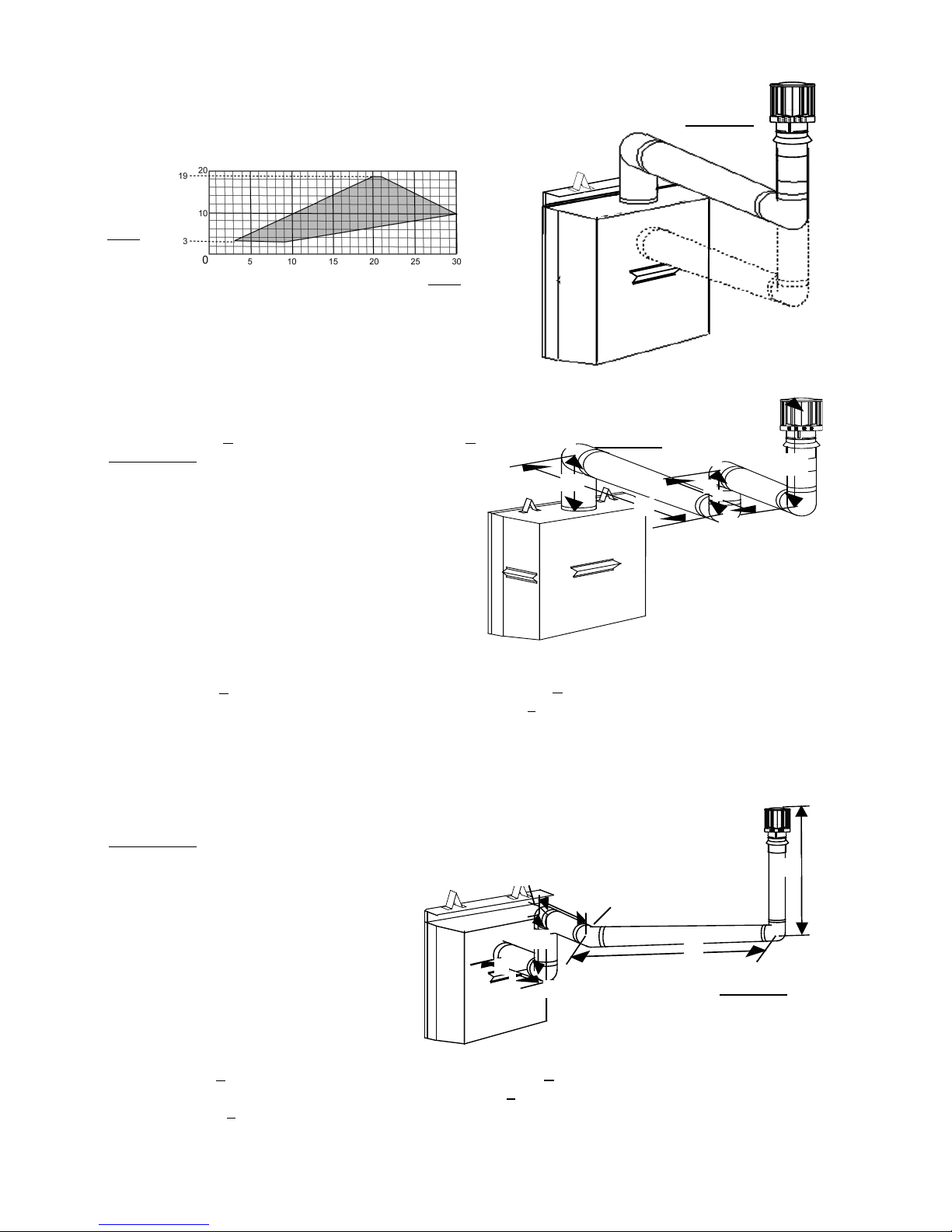
BCDV36CF(G) TOP EXIT / HORIZONTAL TERMINATION
when (HT) < (VT)
Simple venting confi guration (only one 90° elbow)
See graph to determine the required vertical rise V
For vent confi gurations requiring more than one 90° elbow, the following formulas apply:
for the required horizontal run HT.
T
FIGURE 20
11
VERTICAL
RISE IN
FEET
V
T
HORIZONTAL VENT RUN PLUS OFFSET IN FEET H
T
The shaded area within the lines represents acceptable values for HT and V
Formula 1: HT < V
T
Formula 2: HT + VT < 40 feet
Example 1:
V1 = 3 ft
= 8 ft
V
2
VT =
V1 +
V2 =
3 + 8 = 11 ft
H1 = 2.5 ft
= 2 ft
H
2
= H1 + H2 = 2.5 + 2 = 4.5 ft
H
R
= .
03 (three 90° elbows - 90°) = .03(270° - 90°) = 5.4 ft
H
O
HT = HR + HO = 4.5 + 5.4 = 9.9 ft
+ VT = 9.9 + 11 = 20.9 ft
H
T
Formula 1: H
< V
T
9.9 < 11
T
Formula 2: HT + VT < 40 feet
20.9 < 40
Since both formulas are met, this vent confi guration is acceptable.
.
T
H
90°
V
2
2
90°
H
1
90°
V
1
FIGURE 21
W415-0680 / 04.10.08

12
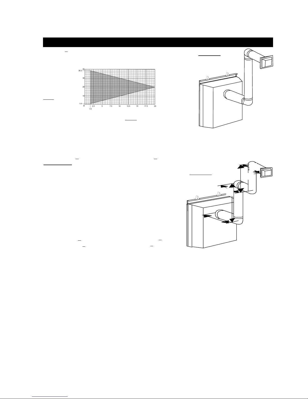
BCDV36CF(G) TOP EXIT / HORIZONTAL TERMINATION
when (HT) > (VT)
Simple venting confi guration (only one 90° elbow)
See graph to determine the required vertical rise VT for the required horizontal
.
run H
T
The shaded area within the lines represents acceptable values for HT and V
REQUIRED VER-
TICAL RISE IN
INCHES V
T
FIGURE 22
.
T
HORIZONTAL VENT RUN PLUS OFFSET IN FEET H
T
For vent confi gurations requiring more than one 90° elbow the following formulas apply:
Formula 1: H
< 4.2 V
T
T
Formula 2: HT + VT < 24.75 feet
Example 2:
V
1
= 6 ft
V
1=VT
=3 ft
H
1
=5 ft
H
2
+ H2 = 3 + 5 = 8 ft
H
R=H1
=.03 (two 90° elbows - 90°) = .03(180° - 90°) = 2.7 ft
H
O
+ HO = 8 + 2.7 = 10.7 ft
H
T=HR
HT + VT =
Formula 1: H
4.2 V
10.7 + 6 =16.7
< 4.2 VT
T
10.7 < 25.2
= 4.2 x 6 = 25.2 ft
T
Formula 2: HT + VT < 24.75 feet
16.7 < 24.75
FIGURE 23
Since both formulas are met, this vent confi guration is acceptable.
Example 3:
= 4 ft
V
1
= 1.5 ft
V
2
H
VT = V1 + V2 = 4 + 1.5 = 5.5 ft
V
H1 = 2 ft
= 1 ft
H
2
= 1 ft
H
3
1
90°
90°
1
H
1
90°
H
H
2
H
V
2
2
H
4
3
H4 = 1.5 ft
HR = H1 + H2 + H3 + H4 = 2 + 1 + 1 + 1. 5 = 5.5 ft
= .03 (four 90° elbows - 90°) = .03(360° - 90°) = 8.1 ft
H
O
HT = HR + HO = 5.5 + 8.1 = 13.6 ft
+ VT = 13.6 + 5.5 = 19.1 ft
H
T
Formula 1: H
4.2 V
< 4.2 VT
T
13.6 < 23.1
= 4.2 x 5.5 = 23.1 ft
T
Since both formulas are met, this vent confi guration is acceptable.
W415-0680 / 04.10.08
Formula 2: H
+ VT < 24.75 feet
T
19.1 < 24.75
FIGURE 24
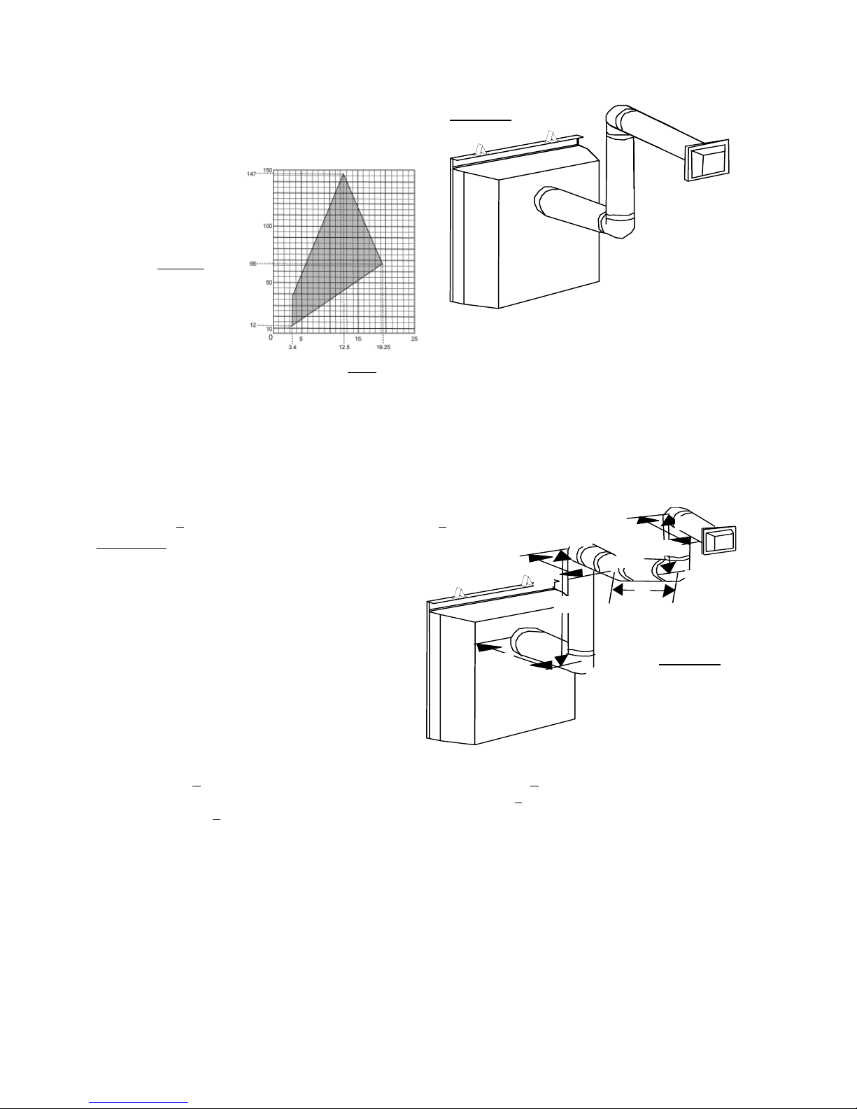
BCDV36CF(G) REAR EXIT / HORIZONTAL TERMINATION
when (HT) < (VT)
Simple venting confi guration (only two 90° elbows)
See graph to determine the required vertical rise VT for the required horizontal
run H
T
REQUIRED VERTICAL RISE IN
FEET V
T
HORIZONTAL VENT RUN PLUS
OFFSETS IN FEET H
T
The shaded area within the lines represents acceptable values for HT and V
For vent confi gurations requiring more than two 90° elbows the following formulas apply:
Formula 1: HT < V
T
Formula 2: HT + VT < 40 feet
Example 4:
= 9 ft
V
1
= 6 ft
V
2
V
=
V1 +
V2 =
T
9 + 6 = 15 ft
H1 = 3 ft
= 2 ft
H
2
= 1.5 ft
H
3
HR = H1 + H2 + H3 = 3 + 2 + 1.5 = 6.5 ft
= .03 (four 90° elbows - 90°)
H
O
= .03(90 + 90 + 90 + 90 - 90) = 8.1 ft
HT = HR + HO = 6.5 + 8.1 = 14.6 ft
+ VT = 14.6 + 15 = 29.6 ft
H
T
Formula 1: H
< V
T
14.6 < 15
T
Formula 2: HT + VT < 40 feet
29.6 < 40
FIGURE 25
.
T
FIGURE 26
H
13
90°
H
3
V
V
2
90°
1
90°
90°
H
2
1
Since both formulas are met, this vent confi guration is acceptable.
W415-0680 / 04.10.08
14
when (HT) > (VT)
FIGURE 27
Simple venting confi guration (only two 90° elbows)
See graph to determine the required vertical rise VT for the required
horizontal run H
T
REQUIRED VERTICAL
RISE IN INCHES
V
T
HORIZONTAL VENT RUN PLUS
OFFSETS IN FEET
The shaded area within the lines represents acceptable values for HT and V
H
T
.
T
For vent confi gurations requiring more than two 90° elbows the following formulas apply:
Formula 1: HT < 3.5V
Example 5:
V1=4 ft
=1.5 ft
V
2
VT=
V1 +
V2 =
4 + 1.5 = 5.5 ft
T
Formula 2: HT + VT < 24.75 feet
H
H1=2 ft
=1 ft
H
2
=1 ft
H
H
3
=1.5 ft
4
H
1
HR=H1 + H2 + H3 + H4 = 2 + 1 + 1 + 1.5 = 5.5 ft
=.03 (four 90° elbows + one 45° elbow - 90°)
H
O
=.03(90 + 90 + 90 + 90 + 45 - 90) = 9.45 ft
HT=HR + HO = 5.5 + 9.45 = 14.95 ft
+ VT= 14.95 + 5.5 = 20.45 ft
H
T
Formula 1: H
3.5VT =
< 3.5V
T
14.95 < 19.25
T
3.5 x
5.5 = 19.25 ft
Formula 2: HT + VT < 24.75 feet
20.45 < 24.75
Since both formulas are met, this vent confi guration is acceptable.
2
V
90°
1
90°
45°
V
H
3
FIGURE 28
90°
H
2
4
90°
W415-0680 / 04.10.08
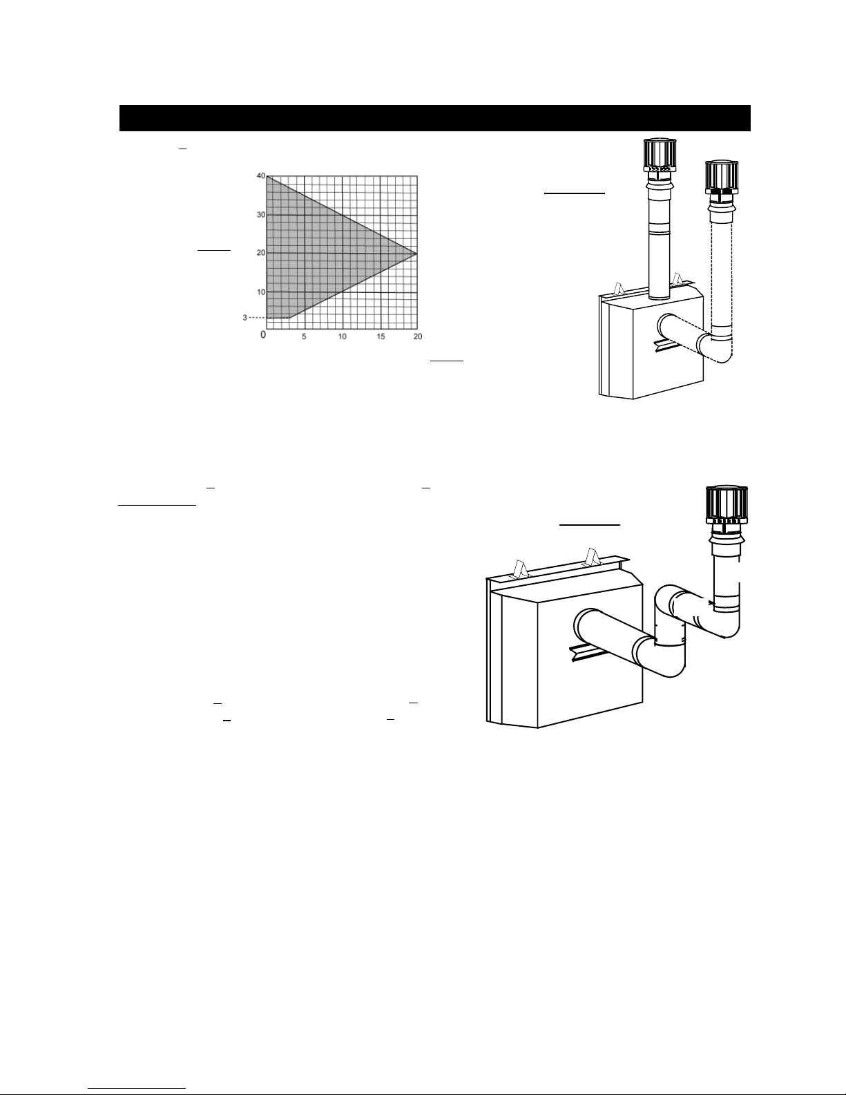
BCDV36CF(G) TOP OR REAR EXIT VERTICAL TERMINATION
when (HT) < (VT)
Simple venting confi guration (only two 90° elbows)
REQUIRED VERTICAL RISE IN FEET
V
T
15
FIGURE 29
HORIZONTAL VENT RUN PLUS OFFSET IN FEET
The shaded area within the lines represents acceptable values for HT and V
See graph to determine the required vertical rise V
for the required horizontal run H
T
H
T
.
T
T
For vent confi gurations requiring more than zero 90° elbow (top exit) or one 90° elbow (rear exit), the following formulas apply:
Formula 1: HT < V
T
Formula 2: HT + VT < 40 feet
Example 6:
V1=5 ft
=10 ft
V
2
VT=
V1 +
V2 =
5 + 10 = 15 ft
H1=3 ft
=2.5 ft
H
2
HR=H1 + H2 = 3 + 2.5 = 5.5 ft
=.03 (three 90° elbows - 90°)
H
O
=.03(90 + 90 + 90 - 90) = 5.4 ft
HT=HR + HO = 5.5 + 5.4 = 10.9 ft
+ VT= 10.9 + 15 = 25.9 ft
H
T
Formula 1: H
10.9 < 15
T
< V
T
Formula 2: HT + VT < 40 feet
25.9 < 40
FIGURE 30
H
1
90°
V
90°
V
2
H
2
1
90°
Since both formulas are met, this vent confi guration is acceptable.
W415-0680 / 04.10.08
16
when (HT) > (VT)
Simple venting confi gurations
See graph to determine the required vertical rise V
for the required horizontal run HT.
T
MAXIMUM
VERTICAL
RISE IN
FEET
V
T
HORIZONTAL VENT RUN PLUS OFFSET IN FEET
H
T
The shaded area within the lines represents acceptable values
for H
and V
T
.
T
For vent confi gurations requiring more than two 90° elbows (top exit) or one 90° elbow (rear exit), the following
formulas apply:
Formula 1: HT < 3V
T
Formula 2: HT + VT < 40 feet
90°
FIGURE 32
Example 7:
= 2 ft
V
1
V
2
V
3
VT =
= 1 ft
= 1.5 ft
V1 +
V2 + V3 =
2 + 1 + 1.5 = 4.5 ft
V
1
H
H1 = 6 ft
= 2 ft
H
2
HR = H1 + H2 = 6 + 2 = 8 ft
= .03 (four 90° elbows - 90°)
H
O
= .03(90 + 90 + 90 + 90 - 90) = 8.1 ft
HT = HR + HO = 8 + 8.1 = 16.1 ft
+ VT = 16.1 + 4.5 = 20.6 ft
H
T
Formula 1: H
< 3V
T
T
3V
= 3 x 4.5 = 13.5 ft
T
Formula 2: H
20.6 < 40
+ VT < 40 feet
T
Since this formula is not met, this vent confi guration is unacceptable.
Since only formula 2 is met, this vent confi guration is unacceptable and a new fi replace location or vent confi guration will
need to be established to satisfy both formulas.
FIGURE 31
90°
V
1
2
90°
H
V
3
2
90°
Example 8:
V1 = 1.5 ft
= 5 ft
V
2
VT =
V1 +
V2 =
1.5 + 5 = 6.5 ft
H1 = 1 ft
= 1 ft
H
2
= 10.75 ft
H
3
HR = H1 + H2 + H3 = 1 + 1 + 10.75 = 12.75 ft
= .03 (three 90° elbows + one 45° elbow - 90°)
H
O
= .03(90 + 90 + 90 + 45 - 90) = 6.75 ft
HT = HR + HO = 12.75 + 6.75 = 19.5 ft
+ VT = 19.5 + 6.5 = 26 ft
H
T
Formula 1: H
3VT =
< 3V
T
19.5 < 19.5
T
3 x
6.5 = 19.5 ft
Since both formulas are met, this vent confi guration is acceptable.
W415-0680 / 04.10.08
90°
H
1
Formula 2: H
26 < 40
+ VT < 40 feet
T
V
H
1
90°
V
2
45°
2
H
3
FIGURE 33
90°
 Loading...