

Page 1
Seaim _nvlcisa "_alning and Edu_etion
I
Electric
Included in this manual is all available information covering
the Continental portable air conditioners. Models are being
sold outside the U.S. as well as inside the U.S. Although the
units may have different model numbers, both the customer
and service information are the same. Listed below are the
European model numbers and the corresponding U.S. model
numbers:
European Model # U.S. Model #
PAC-800 CE71096
PAC-88 CE72096
PAC-88E CE73096
WA-9000 CE75096
WA-9000E CE76096
WA-9000ER CE77096
WA-12000 CE75126
WA-12000E CE76126
WA-12000ER CE77126
Sears Services Training and Education
© 2000 Sears, Roebuck and Co.
Page 2
Electric
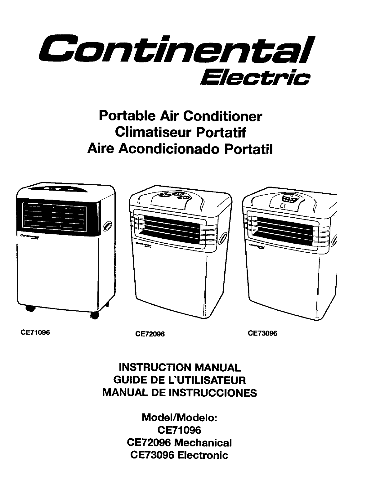
Portable Air Conditioner
Climatiseur Portatif
Aire Acondicionado Portatil
V --""-_
II
CE71096 CE72096 CE73096
INSTRUCTION MANUAL
GUIDE DE L'UTILISATEUR
MANUAL DE INSTRUCCIONES
Model/Modelo:
CE71096
CE72096 Mechanical
CE73096 Electronic
Page 3
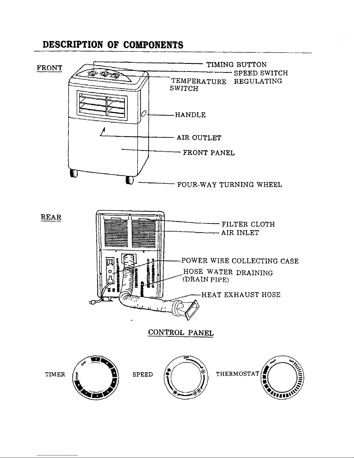
DESCRIPTION OF COMPONENTS
FRONT
TIMING BUTTON
SPEED SWITCH
TEMPERATURE REGULATING
SWITCH
_HANDLE
AIR OUTLET
-- FRONT PANEL
FOUR-WAY TURNING WHEEL
REAR
FILTER CLOTH
AIR INLET
JL-..-]I -_- _POWER WIRE COLLECTING CASE
_Y-----1,_i HOSE WATER DRAINING
_-._K _ /'(DRAIN PIPE)
_I--7-HEATEXHAUSTHOSE
CONTROL PANEL
TIMER
O
SPEED
O
Page 4
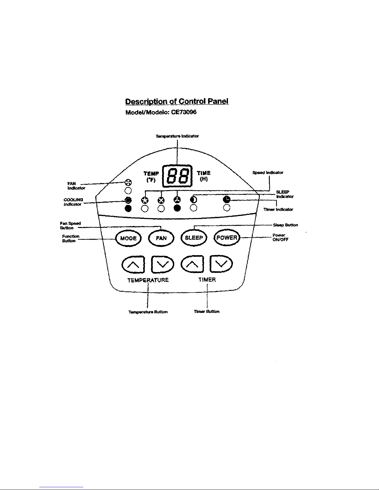
Description of Contro! panel
Model/Modelo: CE73096
Teml_raturetndicatm
FAN
Imllcato¢
COOLING
IndOor
TEMP
0
• Q 0
TIME
(HI
• 0 0
MOOE POWER
_Button
power
ON/OFF
GDGD
T_:_-'_u.m Button Trier Button
Page 5
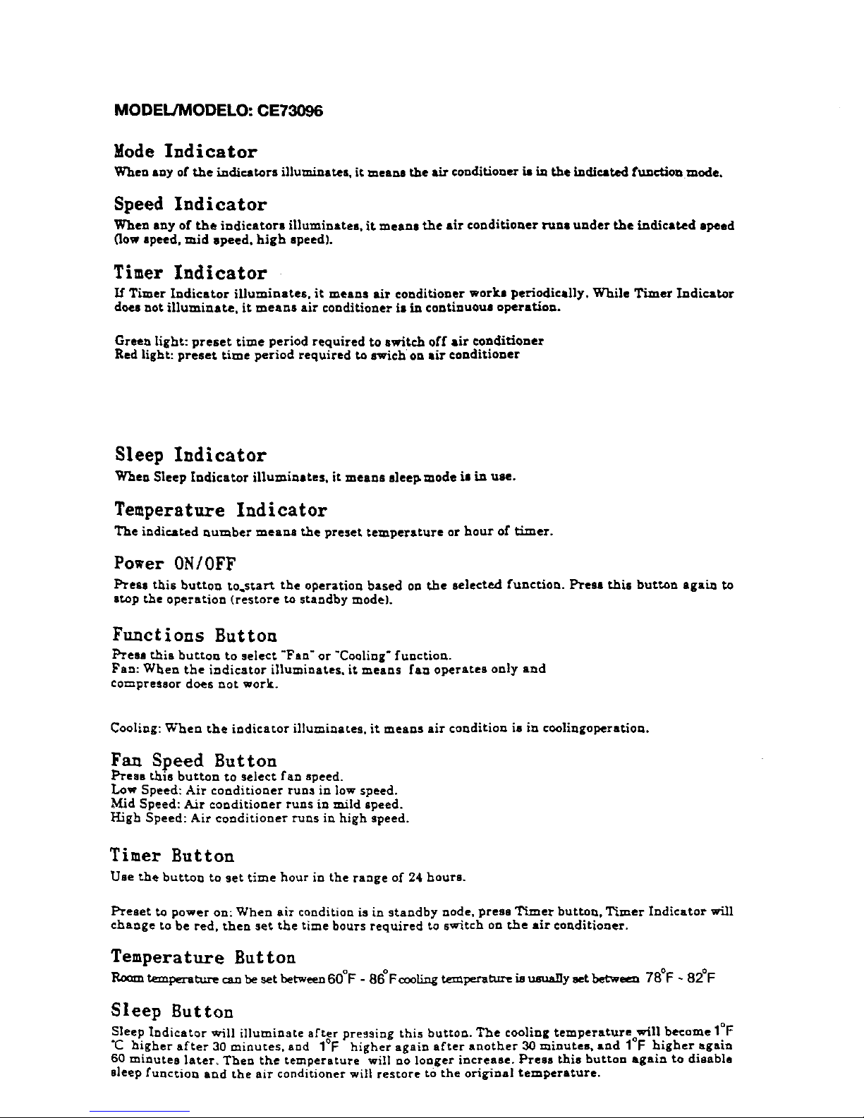
MODEL/MODELO: CE73096
Mode Indicator
When any of the indicators illuminates, it means the air conditioner is in the indicated function mode,
Speed Indicator
When any of theindicatorsilluminates, it meansthe airconditionerruns under the indicated speed
_ow speed, mid speed, high speed).
Timer Indicator
If Timer Indicator illuminates, it means air conditioner works periodically, While Timer Indicator
does not illuminate, it means air conditioner is in continuous operation.
Green light: preset time period required to switch off air conditioner
Red light: preset time period required to swich on air conditioner
Sleep Indicator
When Sleep Indicator illuminates, it means sleel_mode is in use.
Temperature Indicator
The indicated number means the preset temperature or hour of timer.
Power 0N/0FF
Press this button to.start the operation based on the selected function. Press this button again to
stop the operation (restore to standby mode).
Functions Button
Press this button to select"Fan" or "Cooling"function.
Fan: When the indicator illuminates,itmeans fan operates only and
compressor does not work.
Cooling:When the indicatorilluminates,itmeans air condition is in coolingoperation.
Fan Speed Button
Press thisbutton to selectfan speed.
Low Speed: Air conditioner runs inlow speed.
Mid Speed: Air conditioner runs in mild speed.
High Speed: Air conditioner runs inhigh speed.
Timer Button
Use the button to set time hour in the range of 24 hours.
Preset to power on:When air conditionisin standby node, press TLmer buttou,Timer Indicator will
change to be red, then set the time bours required to switch on the air conditioner.
Temperature Button
temperature can be setbetween60°F - 86 °F c_ting t_npex'atu_ iJ usuallysetbetwe_ 78°F ~ 82°F
Sleep Sutton
Sleep Indicator will illuminateafterpressing thisbutton.The coolingtemperatureo,wi!lbecome 1°[:
higher after 30 minutes, and 1 F higher again after another 30 minutes, and I r nigher again
60 minutes later, Then the temperature will no longer increase. Press this button again to disable
sleepfunction and the air conditionerwillrestoretOthe originaltemperature.
Page 6
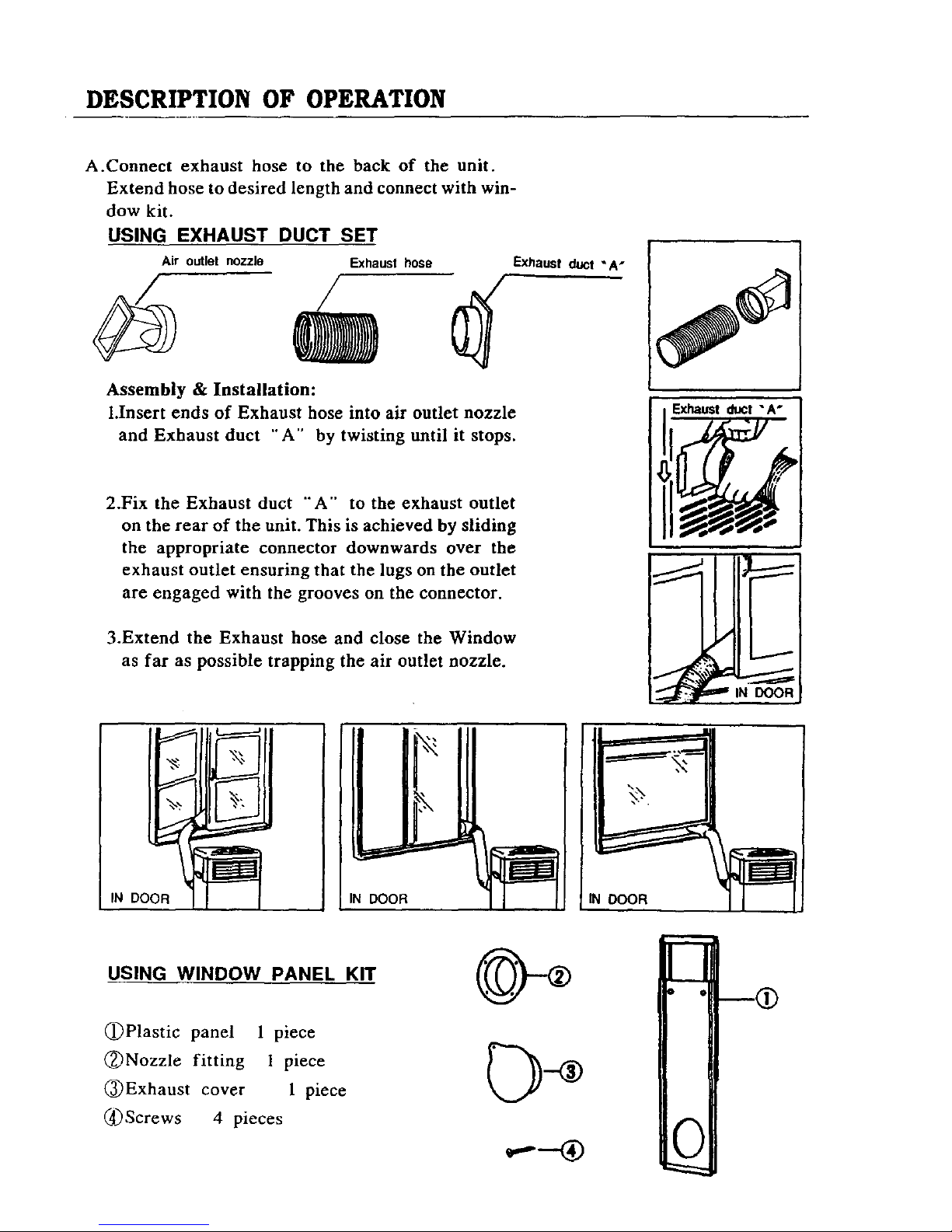
DESCRIPTION OF OPERATION
A.Connect exhaust hose to the back of the unit.
Extend hose to desired length and connect with win-
dow kit.
USING EXHAUST DUCT SET
Air outlet nozzle Exhaust hose
EXhaust duct "A n
Assembly & Installation:
l.Insert ends of Exhaust hose into air outlet nozzle
and Exhaust duct "A" by twisting until it stops.
2.Fix the Exhaust duct "A'" to the exhaust outlet
on the rear of the unit. This is achieved by sliding
the appropriate connector downwards over the
exhaust outlet ensuring that the lugs on the outlet
are engaged with the grooves on the connector.
3.Extend the Exhaust hose and close the Window
as far as possible trapping the air outlet nozzle.
EXhaust duct "A"
DOOR IN
I
IN DOOR
USING WINDOW PANEL KIT
(_)Plastic panel 1 piece
(_)Nozzle fitting 1 piece
(_)Exhaust cover 1 piece
(4) Screws 4 pieces
n
D OI
i
0
Page 7
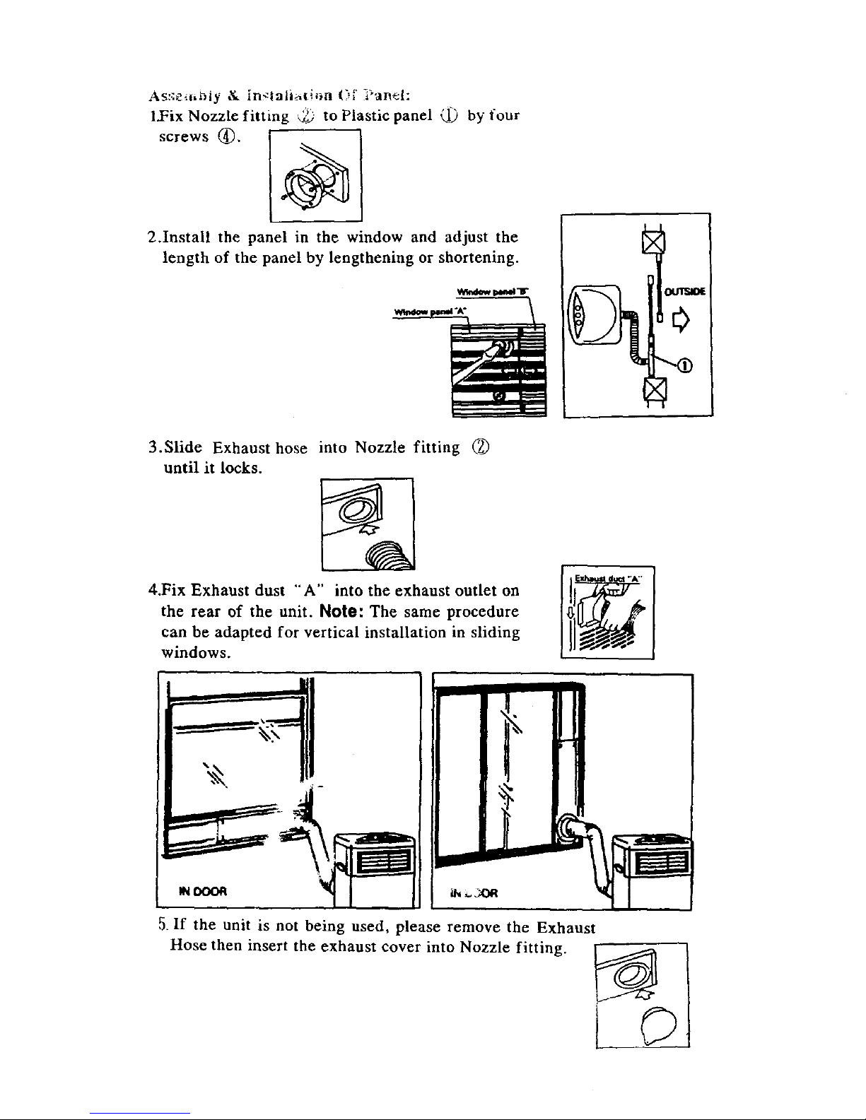
As:.:e.,_tLl-_ty & in_lati_li_a _3_' _anel:
l.Fix Nozzle fitting , :'_ to Plastic panel _ by four
screws I
2.Install the panel in the window and adjust the
length of the panel by lengthening or shortening.
|lol !
3.Slide Exhaust hose into Nozzle fitting (_
until it locks.
4.Fix Exhaust dust "A" into the exhaust outlet on
the rear of the unit. Note: The same procedure
can be adapted for vertical installation in sliding
windows.
iN,.,,X_
5. If the unit is not being used, please remove the Exhaust
Hose then insert the exhaust cover into Nozzle fitting.
Page 8
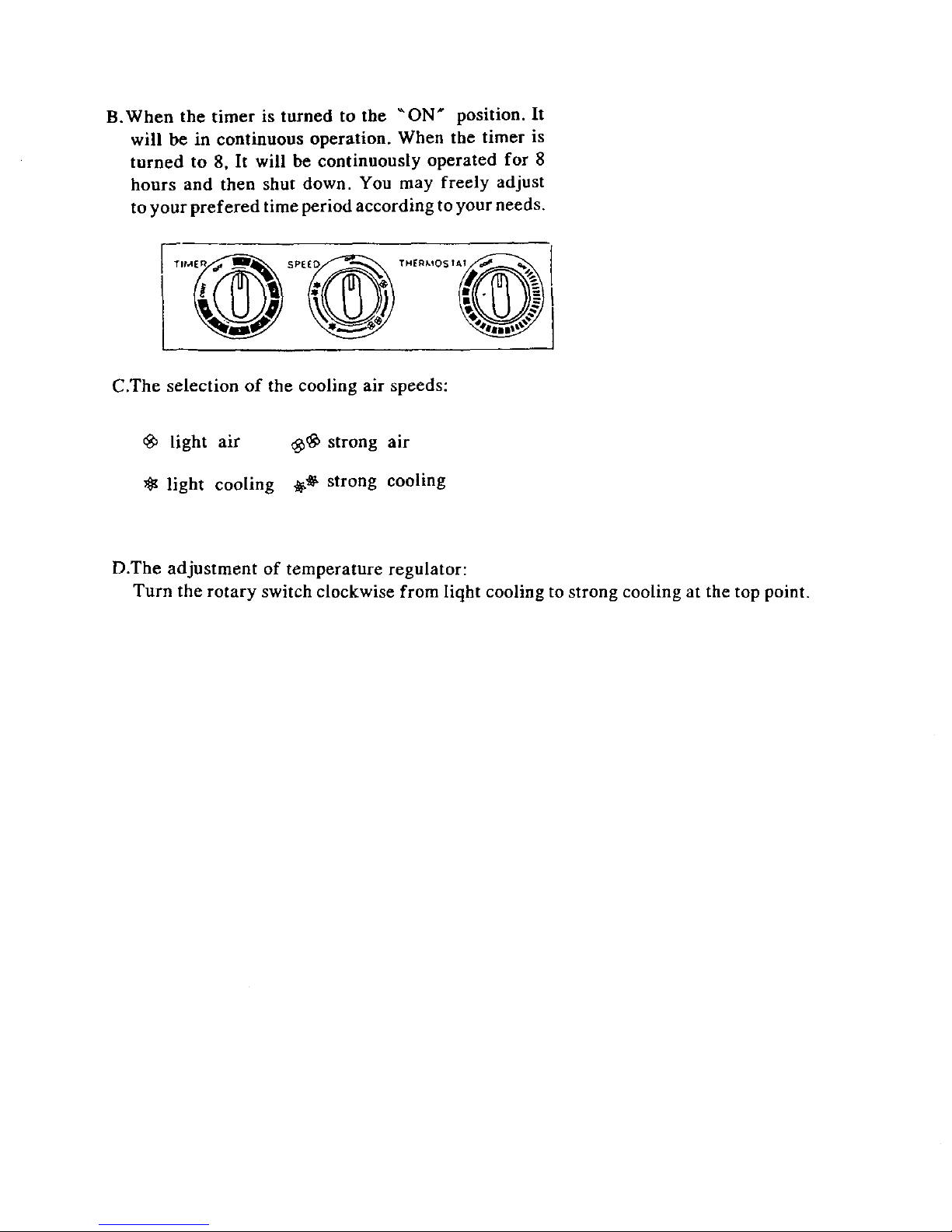
B.When the timer is turned to the "ON" position. It
will be in continuous operation. When the timer is
turned to 8. It will be continuously operated for 8
hours and then shut down. You may freely adjust
to your prefered time period according to your needs.
C.The selection of the cooling air speeds:
light air _b_ strong air
:_ light cooling _ strong cooling
D.The adjustment of temperature regulator:
Turn the rotary switch clockwise from liqht cooling to strong cooling at the top point.
Page 9
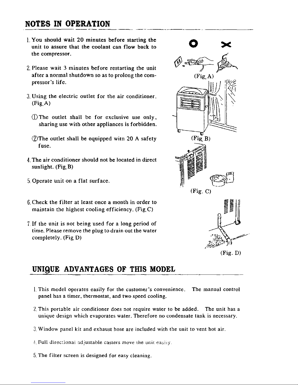
NOTES IN OPERATION
1. You should wait 20 minutes before starting the
unit to assure that the coolant can flow back to
the compressor.
2. Please wait 3 minutes before restarting the unit
after a normal shutdown so as to prolong the com-
pressor's life.
3. Using the electric outlet for the air conditioner.
(Fig.A)
(DThe outlet shall be for exclusive use only,
sharing use with other appliances is forbidden.
(_)The outlet shall be equipped wim 20 A safety
fuse.
4. The air conditioner should not be located in direct
sunlight. (Fig.B)
5. Operate unit on a flat surface.
6. Check the filter at least once a month in order to
maintain the highest cooling efficiency. (Fig.C)
7.If the unit is not being used for a long period of
time. Please remove the plug to drain out the water
completely. (Fig. D)
O
(Fig.A)
_ /r
-3
(Fig. B)
(Fig. C)
(Fig. D)
UNIQUE ADVANTAGES OF THIS MODEL
l, This model operates easily for the customer's convenience. The manual control
panel has a timer, thermostat, and two speed cooling.
2. This portable air conditioner does not require water to be added. The unit has a
unique design which evaporates water. Therefore no condensate tank is necessary.
3. Window panel kit and exhaust hose are included with the unit to vent hot air.
-! Full directional adjustable casters move the unit easiiy.
5. The filter screen is designed for easy cleaning.
Page 10
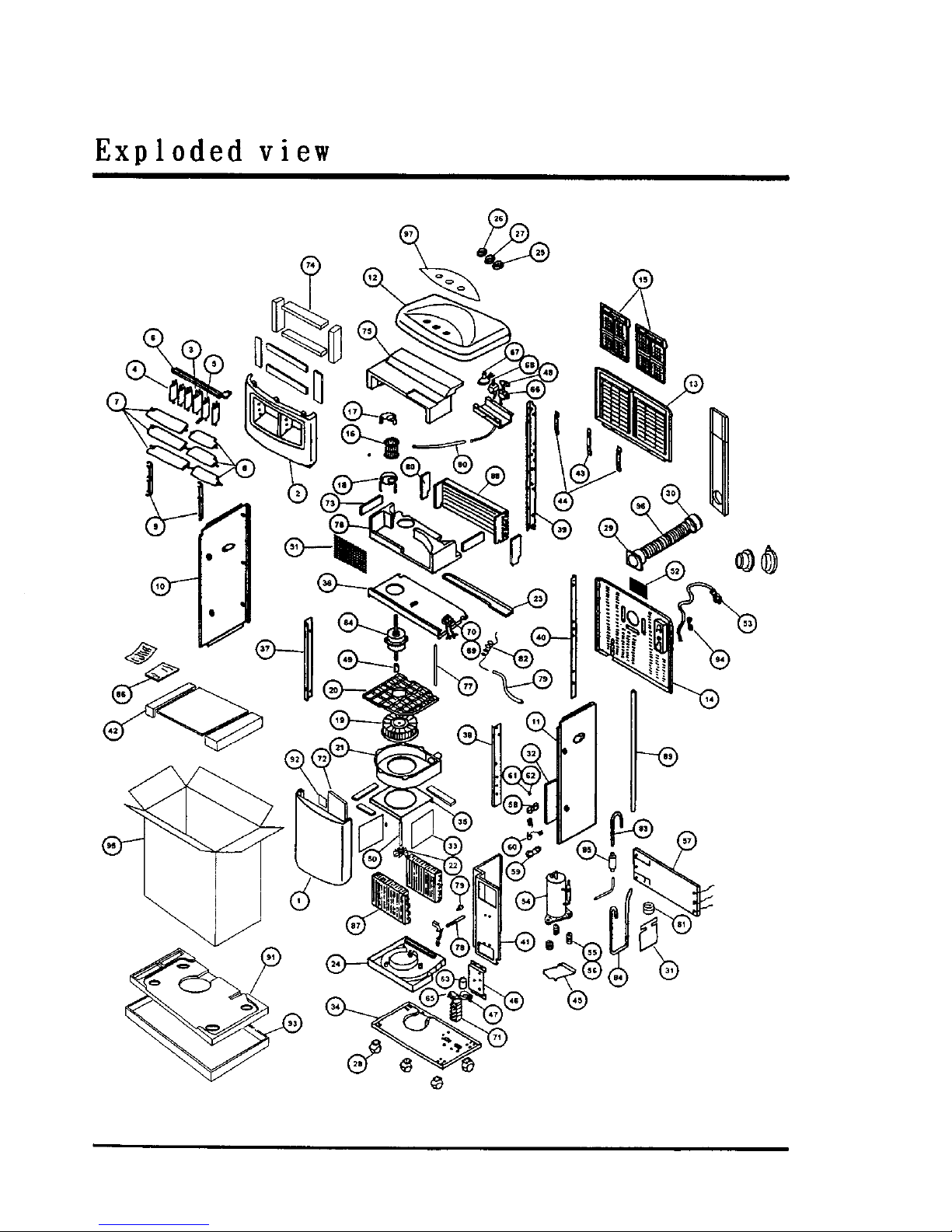
Exploded view
Page 11
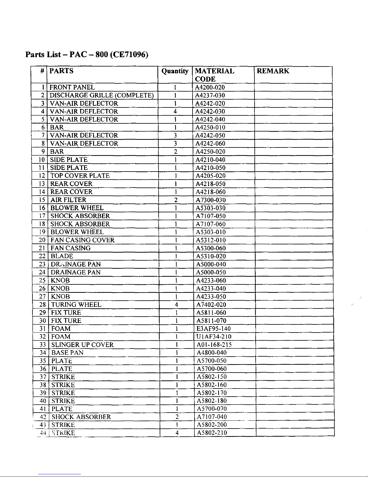
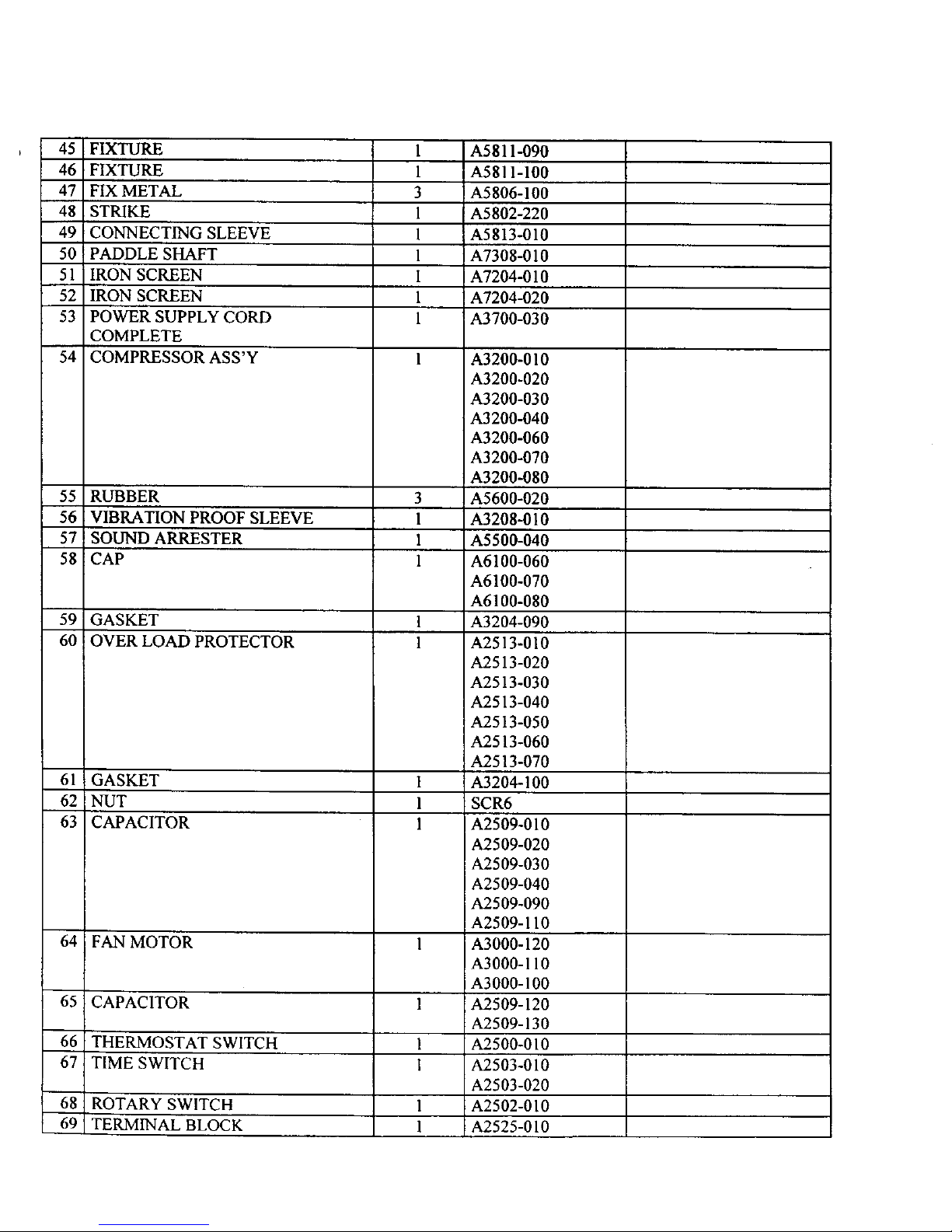
Parts List - PAC - 800 (CE71096)
#
1
2
3
4
5
6
7
8
9
10
11
12
13
14
15
16
17
18
19
2O
21
22
23
24
25
26
27
28
29
30
31
32
33
PARTS
FRONT PANEL
DISCHARGE GRILLE (COMPLETE)
VAN-AIR DEFLECTOR
VAN-AIR DEFLECTOR
VAN-AIR DEFLECTOR
BAR
VAN-AIR DEFLECTOR
VAN-AIR DEFLECTOR
BAR
SIDE PLATE
SIDE PLATE
TOP COVER PLATE
REAR COVER
REAR COVER
AIR FILTER
BLOWER WHEEL
SHOCK ABSORBER
SHOCK ABSORBER
BLOWER WHEEL
FAN CASING COVER
FAN CASING
BLADE
DR, ,INAGE PAN
DRAINAGE PAN
KNOB
KNOB
KNOB
TURING WHEEL
FIX TURE
FIX TURE
FOAM
FOAM
SLINGER UP COVER
Quantity
1
1
1
4
|
1
3
3
2
1
1
1
1
1
2
1
1
1
1
1
I
1
1
1
1
1
1
4
1
1
1
1
1
MATERIAL
CODE
A4200-020
A4237-030
A4242-020
A4242-030
A4242-040
A4250-010
A4242-050
A4242-060
A4250-020
A4210-040
A4210-050
A4205-020
A4218-050
A4218-060
A7300-030
A5303-030
A7107-050
A7107-060
A5303-010
A5312-010
A5300-060
A5310-020
A5000-040
A5000-050
A4233-060
A4233-040
A4233-050
A7402-020
A5811-060
A5811-070
E3AF95-140
U1AF34-210
A01-168-215
34 BASE PAN 1 A4800-040
35 PLATE 1 A5700-050
36 PLATE 1 A5700-060
37 i STRIKE 1 A5802-150
38 STRIKE 1 A5802-160
39 STRIKE 1 A5802-170
40 ' STRIKE 1 A5802-180
41 PLATE 1 A5700-070
42 SHOCK ABSORBER 2 A7107-040
43 STRIKE 1 A5802-200
44 _FI<IKE 4 A5802-210
REMARK
Page 12
45 FIXTURE
46 FIXTURE
47 FIX METAL
48 STRIKE
49 CONNECTING SLEEVE
50 PADDLE SHAFT
51 IRON SCREEN
52 IRON SCREEN
53 POWER SUPPLY CORD
COMPLETE
54 COMPRESSOR ASS'Y
55 RUBBER
56 VIBRATION PROOF SLEEVE
57 SOUND ARRESTER
58 CAP
1
1
3
1
1
1
1
1
1
3
1
1
1
59 GASKET 1
60 OVER LOAD PROTECTOR 1
61 GASKET
62 NUT
63 CAPACITOR
64 FAN MOTOR
65 CAPACITOR
66 THERMOSTAT SWITCH
67 TIME SWITCH
68 ROTARY SWITCH
69 TERMINAL BLOCK
1
1
1
1
1
I
1
1
A5811-090
A5811-100
A5806-100
A5802-220
A5813-010
A7308-010
A7204-010
A7204-020
A3700-030
A3200-010
A3200-020
A3200-030
A3200-040
A3200-060
A3200-070
A3200-080
A5600-020
A3208-010
A5500-040
A6100-060
A6100-070
A6100-080
A3204-090
A2513-010
A2513-020
A2513-030
A2513-040
A2513-050
A2513-060
A2513-070
A3204-100
SCR6
A2509-010
A2509-020
A2509-030
A2509-040
A2509-090
A2509-110
A3000-120
A3000-110
A3000-100
A2509-120
A2509-130
A2500-010
A2503-010
A2503-020
A2502-010
A2525-010
Page 13
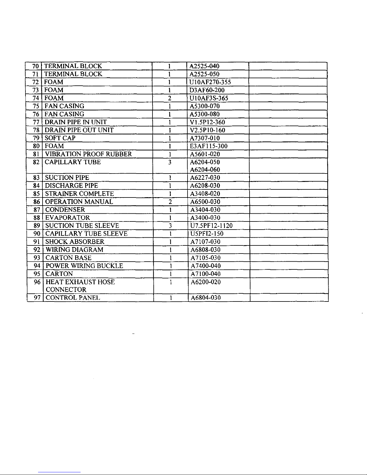
70 TERMINAL BLOCK
71 TERMINAL BLOCK
72 FOAM
73 i FOAM
74 FOAM
75 FAN CASING
76 FAN CASING
77 ! DRAIN PIPE IN UNIT
78 DRAIN PIPE OUT UNIT
79 I SOFT CAP
80 FOAM
81 VIBRATION PROOF RUBBER
82 CAPILLARY TUBE
1
1
1
1
2
1
l
1
!
1
l
1
3
83 SUCTION PIPE 1
84 DISCHARGE PIPE 1
85 STRAINER COMPLETE 1
86 OPERATION MANUAL 2
87 CONDENSER 1
88 EVAPORATOR 1
89 SUCTION TUBE SLEEVE 3
90 CAPILLARY TUBE SLEEVE !
91 SHOCK ABSORBER 1
92 WIRING DIAGRAM !
93 CARTON BASE 1
94 POWER WIRING BUCKLE 1
95 CARTON 1
96 HEAT EXHAUST HOSE 1
CONNECTOR
97 CONTROL PANEL 1 A6804-030
A2525-040
A2525-050
U10AF270-355
D3AF60-200
UIOAF3S-365
A5300-070
A5300-080
VI.SP12-360
V2.5P10-160
A7307-010
E3AF115-300
A5601-020
A6204-050
A6204-060
A6227-030
A6208-030
A3408-020
A6500-030
A3404-030
A3400-030
U7.5PFI2-1120
U5PFI2-150
A7107-030
A6808-030
A7105-030
A7400-040
A7100-040
A6200-020
Page 14
Continental
_ec_r'ic
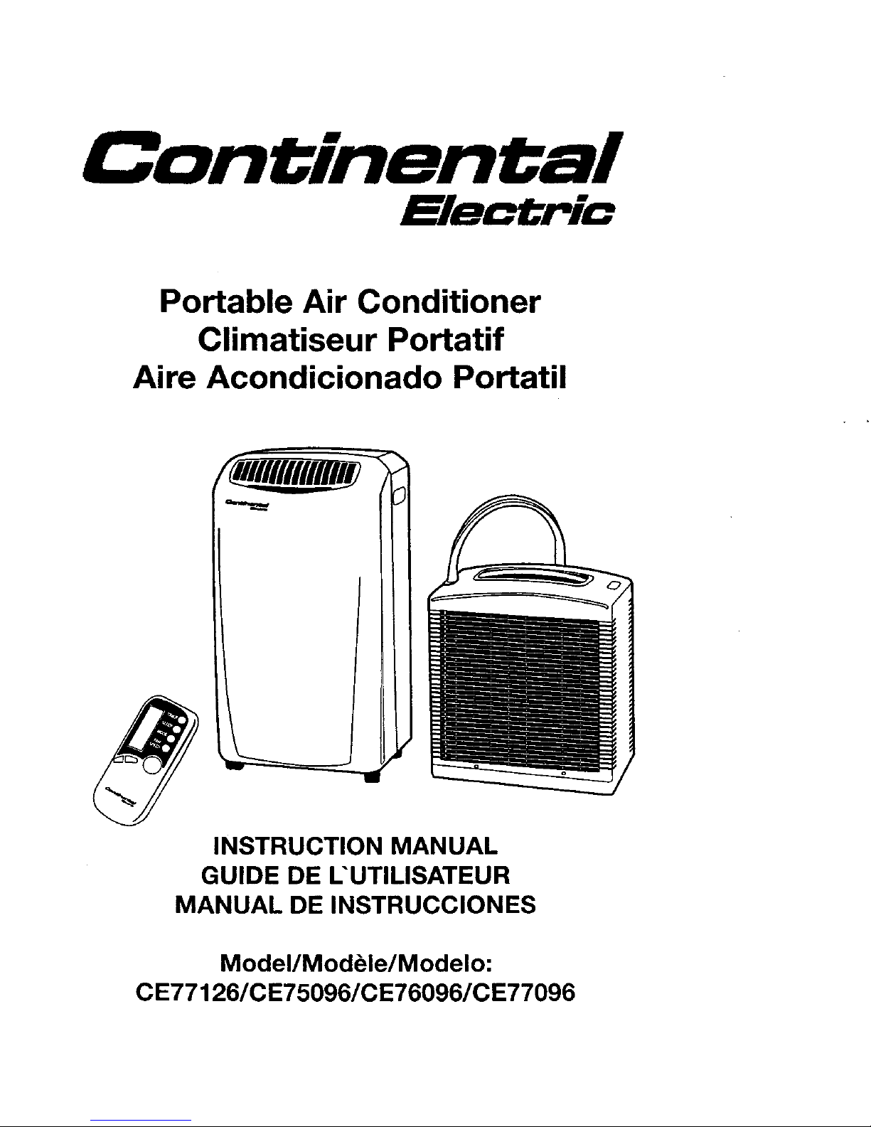
Portable Air Conditioner
Climatiseur Portatif
Aire Acondicionado Portatil
INSTRUCTION MANUAL
GUIDE DE L'UTILISATEUR
MANUAL DE INSTRUCCIONES
Model/Modble/Modelo:
CE77126/CE75096/CE76096/CE77096
Page 15
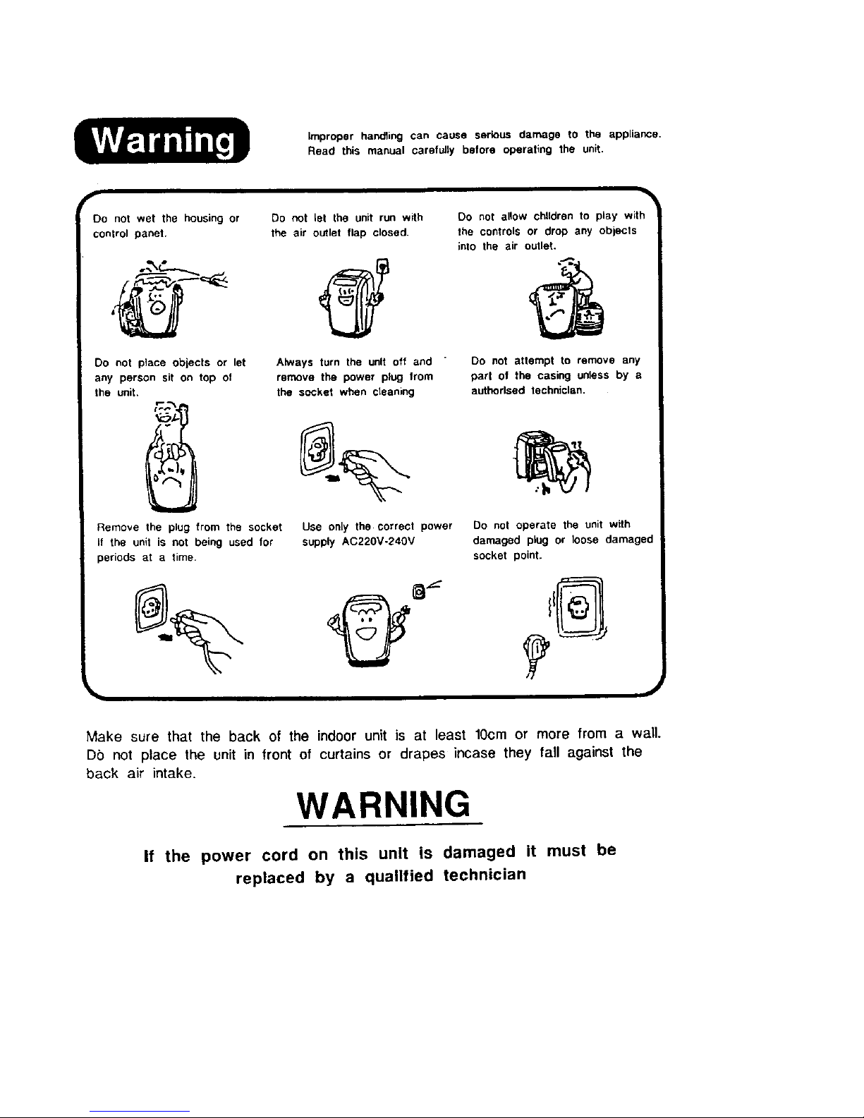
Improper handling can cause serious damage to the appliance.
Read this manual carefully before operating the unit.
f
Oo not wet the housing or
control panel
Do not place obiects or let
any person sit on top of
the unit.
_c_
C
Remove the plug from the socket
if the unit is not being used for
periods at a time.
Do not let the unit run with
the air outlet flap closed.
Always turn the unit off and "
remove the power plug from
the socket when cleaning
Use only the correct power
supply AC220V-24OV
Do not allow chUdren to play with
the controls or drop any objects
into the air outlet.
Do not attempt to remove any
part of the casing unless by a
authorlsed technician.
Do not operate the unit with
damaged plug or loose damagec
socket point.
Make sure that the back of the indoor unit is at least lOcm or more from a wall.
Do not place the unit in front of curtains or drapes incase they tall against the
back air intake.
WARNING
If the power cord on this unit is damaged it must be
replaced by a qualified technician
Page 16
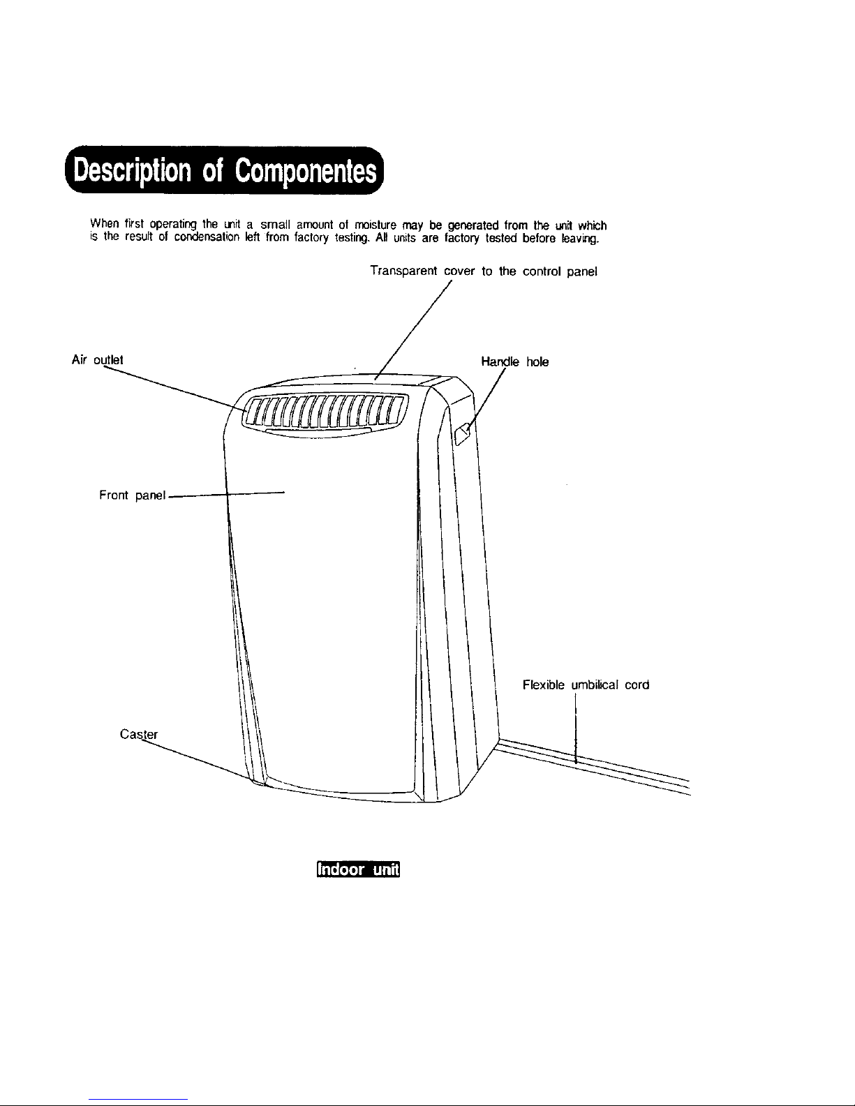
When first operating the unit a small amount of moisture may be generated lrom the unit which
is the result of condensation left from factory testing. All units are factory tesled before leaving.
Transparent cover to the control panel
Air outlet Handle hole
Front panel
Flexible umbilical cord
Caster
Page 17
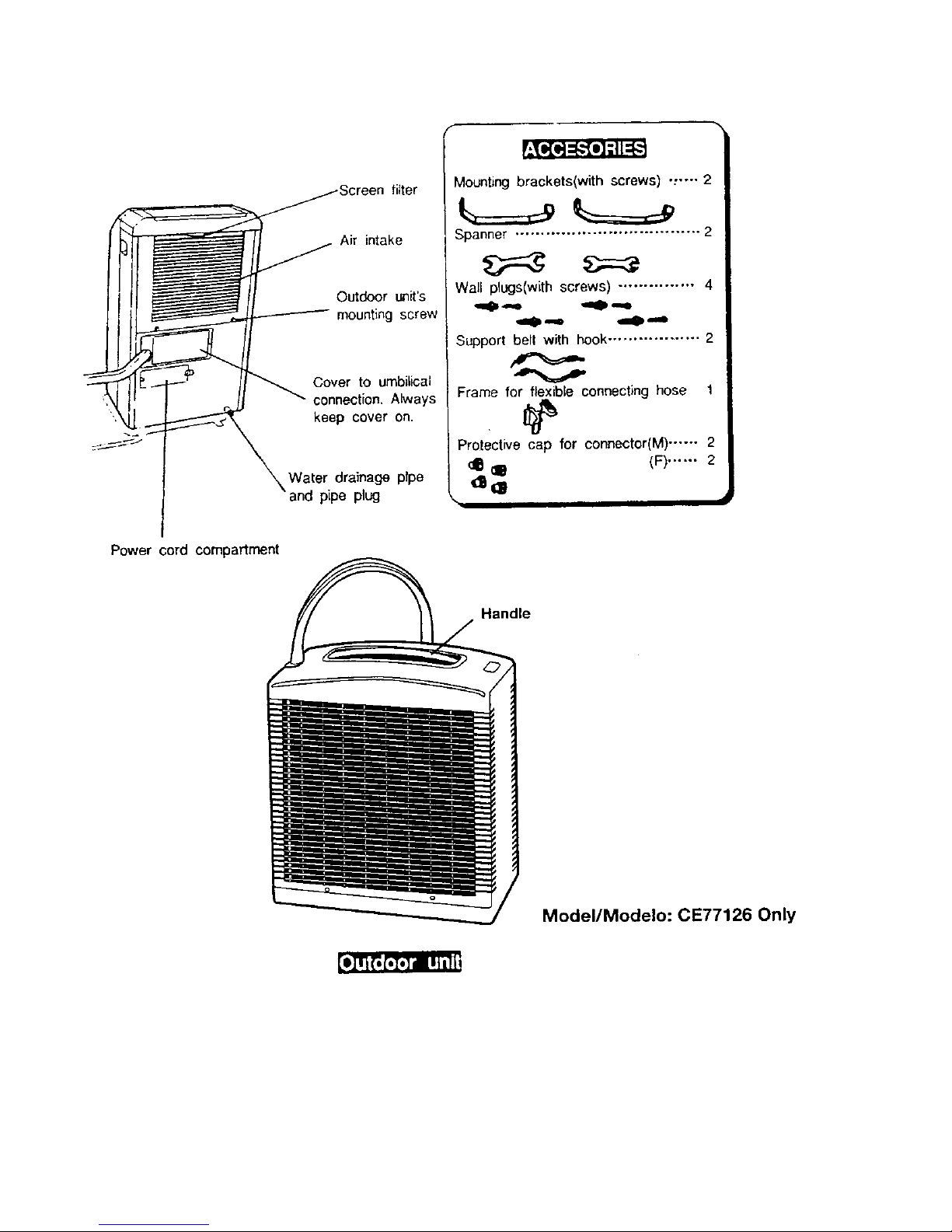
Screenfilter
tl _ II O.,_r _i,'s
"_,_ ._ _ _" kO:npe_toOerAon.ays
Mounting brackets(with screws) ._--. 2
_=__ /
,Spanner .................................... 21
Wall plugs(with screws) ............... 4|
"---- "=-- /
Support _hook .................. 2/
Frame,or b,econnectinghose'/
Protective cap for connector(M) ...... 2/
_IB (ll (F)...... 2/
/
\ ,,, , J
Power cord compartment
Handle
Model/Modelo: CE77126 Only
Page 18
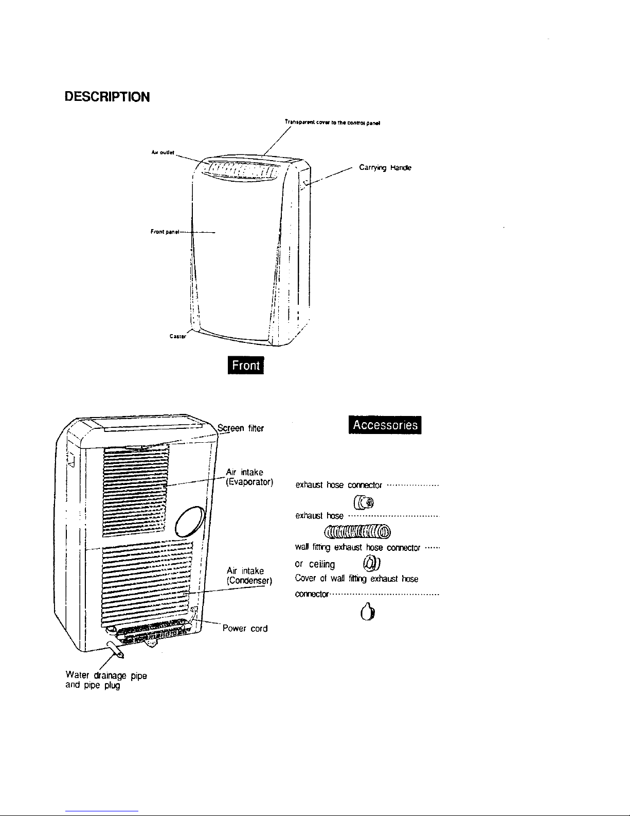
DESCRIPTION
Tr_$_r_t COVW to the ¢entto_ panel
/
FtQnlplnl_-- .__
P,
!_ Iii
Care!w',gHande
Air intake
Air intake
(Condenser)
Power cord
exhaust hose connector ...................
exhaust hose ................................
wan fit_ exhaust hose connector ......
or ceiling (,_
Cover ol wai_fitting exhausthose
connector .......................................
Water draina_;epipe
and pipe plug
Page 19
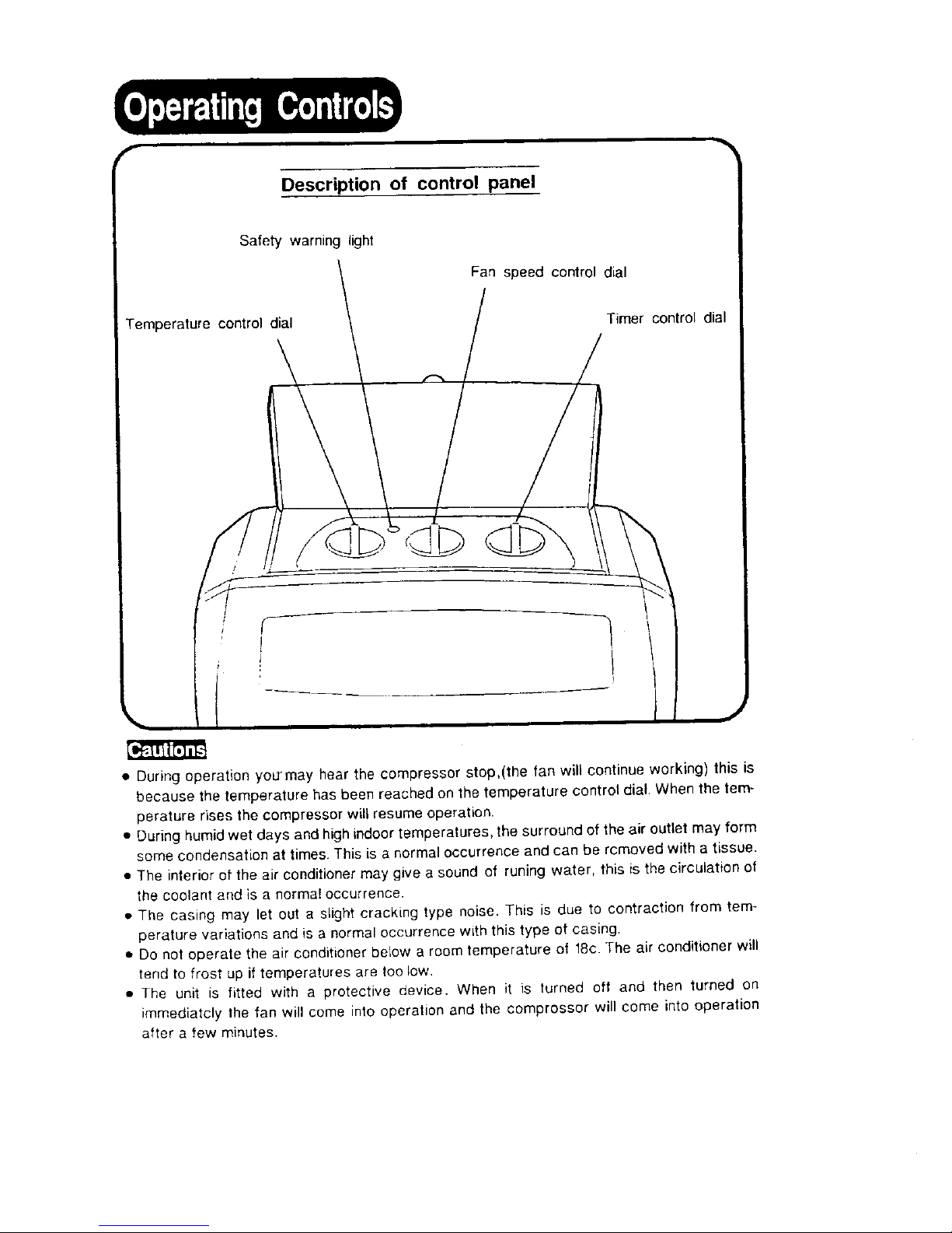
Description of control panel
Safety warnin0 light
Fan speed control dial
Temperature control dial
Timer control dial
• During operation yoU_may hear the compressor stop,(the fan will continue working) this is
because the temperature has been reached on the temperature control dial. When the tem-
perature rises the compressor will resume operation.
• During humid wet days and high indoor temperatures, the surround of the air outlet may form
some condensation at times. This is a normal occurrence and can be rcmoved with a tissue.
• The interior of the air conditioner may give a sound ot runing water, this is the circulation of
the coolant and is a normal occurrence.
• The casing may let out a slight cracking type noise. This is due to contraction from tem-
perature variations and is a normal occurrence with this type of easing.
• Do not operate the air conditioner below a room temperature ot 18c The air conditioner will
tend to frost up if temperatures are too low.
• The unit is fitted with a protective device. When it is turned off and then turned on
immediately the fan will come into operation and the comprossor will come into operation
after a few minutes.
Page 20
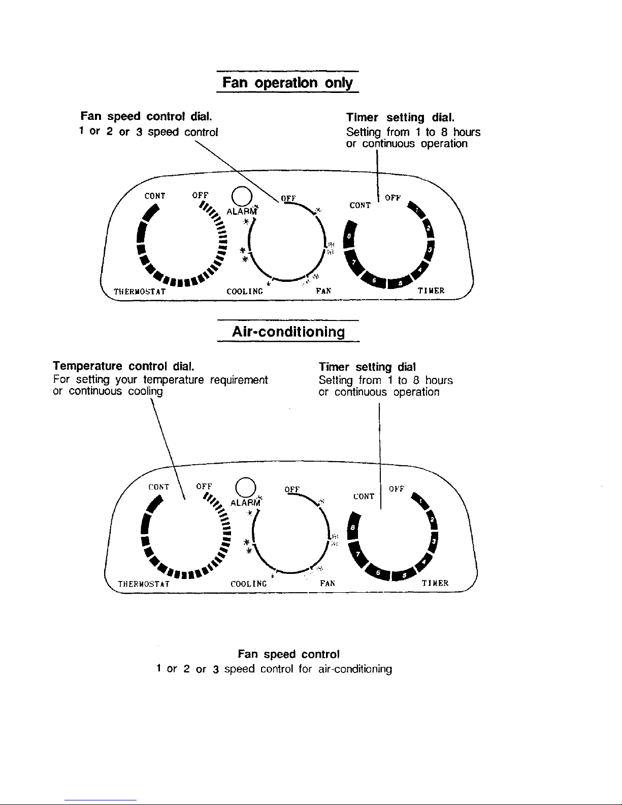
Fan operation only
Fan speed control dial.
t or 2 or 3 speed control
CONT OFF
Timer setting dial.
Setting from 1 to 8 hours
or continuous operation
OFF OFF
THERMOSTAT COOLING P; TIMER
Air-conditioning
Temperature control dial.
For setting your temperature requirement
or continuous cooling
Timer setting dial
Setting from 1 to 8 hours
or continuous operation
OFF
CONT
TII4ER
Fan speed control
1 or 2 or 3 speed control for air-conditioning
Page 21

Control Panel
Model/Modelo: CE76096 Only
[_oe [_]o ,_
_o0 _o_ o o
@@®©@@
(( (
12 "On/OfF key
13 Alarm light: comes on when the condensatecollecting tank
isfull.
14 "Function" key: (or selectingthe operating mode:ventilation
only or air conditioning: the light (a) or (b) comes on
depending on the mode chosen.
15 Ventilation speedselectionkey
Light{c)on: slow ventilation speed
Light (d) on: medium ventilation speed
Light (e) on: high ventilation speed
16 "Night operation" key:the light (f) comeson.
17 "Programming" keys: according to the type of program-
ming chosen (see page 10), a green or red light comes
on(g).
18 Temperatureselectionkeys
19 Digital display dial
REMOTE CONTROL
Model/Modelo: CE77096 Only
25 KeyForenabling and settingthe timer
26 Key for enabJing the night mode ©
27 Keyfor selectingthe ventilation speed
28 Keybr selecting the operating mode
29 Key On/Off
Page 22

• Periodiccleaning and maintenance may maximize the
air condition'sfunctions and optimal condition.
• Prior to cleaning and maintenance, please make sure
to temove the plug from power socket to ensure safety.
#,r
Filter cleaning
Check once a week
• Use lukewarm water and very mild
detergent when washing fgter rinse
with clean cold water
• Use a vacuum or brush to remove
fluff/dust from the filter.
Maintenance on the front
panel and housing
• Do not use chemicals or solvents
for cleaning the unit.
• Use a damp cloth for cleaning.
You may use a mild detergent to
remove stubborn stains.
Maintenance for the
outdoor unit
• Check the out door unit periodicallyand
ctear any foreign objects, leaves and paper
that may be there. If possible try to keep
the unit shaded from strong direct sun light.
End of season maintenance
1.Removethe water drainirE:Jplug located at
the rear bottom of the air conditioner,
replace the plug after the condensation
has been drained from the water tank.
2.Turm on the fan operation for a period
ot time to dry the interior of the air
conditioner.
3.Stop the operation,and remove the power
cord plug Item the wallpower socket and
store it into the power cord comparment
located on the rear of the indoorunit+
4.Wipe clean the outdoorunit and hang it to
the back of the indoor unit.
5.Coverthe air conditionerbefore putting it in
the storage.
Page 23

p,-
Clean the filter periodically
• When using it in normal conditions,
please clean the filter at least once
every two weeks
.....
• it you are using the unit in an area
with excessive dust/fluff make sure
you check and clean filter each week.
- ...
• If the screen is not kept clean it can
increase your power consumption
and reduce the cooling efficiency.
• Pedodls cleaning, maintenance and proper
use may not only maximize the air
conditioner's functions, but also can avoid
increasing unnecessary expense.
Take note of the following
points
• Avoid direct sun lighton the unit
• Maintain proper ventilation around
lhe unit.
• Avoid opening doors and windows
as much as possible.
• Avuid excessive number of peopre
in the room.
Page 24

Steps in disassembly
t,Turn off the air conditioner,and remove
the plug from the power sucket
Upon turning off the air conditioner, leave
it idle for at least 30 minutes; the
disassembly can then be implemented
after the system has been stabilized.
%
2.Use a Philips-head screw driver to
remove the cover.
3Disconnect the electrical connector
by pressing clip holders.
4,Remove the metal holding brackets
5.Remove the insulatingfoam around
the upper connector.
• This procedure should be carried out by
a professional person to avoid expensive
mistakes.
6.Use the 2 spanners provided to
disconnect the 2 pipes,
Make sure the tubes and connectors
are kept level while disconnecting to
avoid coolant leaking.
7,Screw the protective caps onto the
ends after disconnection of each pipe
8.Separate the clamping tie on the black
Water pipe, Gradually release the water
pipe and place your finger over the end
to prevent water in the tube coming out.
Have a conta_,ler ready to collect any
excess water from the tube.
Steps in connecting
• Always remember to keep the
connecting pipes level with
the connecing point when
re-assembllog
• When re-connecting the uni[ follow the
above steps in reverse.
• Use your fingers to connectthe threads
and then t_hten with the spanners
provided
• After connectionplease use soap suds
to check for leaks in the coolant pipe.
Please remember, this procedure must be
followed each time.
J
MODEL/MODELO: 0E77126
Page 25

F
IMPORTANT: Do not have any sharp hands or twisting
it the umbilicalcord.
For permancnt installation follow instructlens. If you are
not sure contact a service company.
The Indoor Unit
• METHOD I :
The umbilical cord can pass through partly open door or window.
The location of the indoor unit must
have at lease 10cm space at the rear
and away from curtains/drapes.
_,METHOD II :
The umbilical cord can be passed through a hole in the window or the window
frame were a gap has been shaped out.
When using the later use the
plastic frame supplied. When the
air conditioner is being stored
away cap can be placed over the
frame to seal the hole off.
• METHOD tll :
For fitting through a hole in the wall disconnectthe umbilical cord as described
on page 8 and pass cord through the hole from the outside. Use the plastic
tramo for the umbilical cord when using this mcthod.
• if you are not sure or happy
disconnecting and reconnecting
the cord contact a
local service person.
• Remember to use soap suds
to check for refrigerant leaks
after conncctlen each time,
II
Page 26

The Installation of heat exhaust hose
Model/Modelo: CE75096, CE76096, CE77096
USING EXHAUST DUCT SET
1.Connect one heat exhaust hose connector anti-clockwise to the heat exhaust
hose.
2.Connect the other heat exhaust hose anti-clockwise to the other end of
heat exhaust hose then connect the connector to the appliance clockwise.
&Extend the exhaust hose and close the window as far as possible trapping
the heat exhaust hose connector.
U
i
k
INDOOR
DOOR
USING WINDOW PANEL KIT
j_Plastic panel 1 piece
._Nozzle fitting 1 piece
.,3)Exhaust cover 1 piece
:4_>Screws 4 pieces
!===='IN DOOR
C3
D 0 m(_)
0
Page 27

The Installation of window panel kit
Model/Modelo: CE75096, CE76096, CE77096
Assembly & Installation Of Panel:
1.Fix Nozzle fittin ,_ to Plastic )anel .U_with four screws _)
\
®
2.Install the panel in the window and adjust
the length of the panel by lengthening or
shortening.
3.Connect the heat exhaust hose connector anti-clockwise to the heat exhaust hose; then slide
the hose into Nozzle fitting 2 until it locks.
4.Connect the other heat exhaust hose anti-clockwise to the another end of heat exhaust hose;
then connect the connector to the appliance clockwise.4.
Note:The same procedure can be adapted for vertical installation in sliding widows.
- ..'t-
I
14 DOOR
5 If the unit is not being used. please remove the Exhaust Hose; then insert the exhaust cover
into nozzle fitting, r_
©l
Page 28

Warning
Each time you bring the outdoor unit insidealways turn the air eondilioneroff at the
power supply If you do not and move the insideunit the debumidif'_l water in the
container inside the unit couldactivate the water pump and discard water from the
tube on the outdoor unit,
The Outdoor Unit
Model: CE77126 Only
• METHOD I :
The outdoor unit may be placed on outdoorpatio or flower planer directly, so it
does not require the special mounting brackets.
PTease make sure that the drainage
pipe is not pressed by the outdoor
unit! 5_,,
120¢i
(Open space) 1
• METHOD II :
The outdoor unit may be mounted on the wall by utilizing the enclosed accessories
(mounting brackets, wall plug and the screws).
When using this method you can
extend the drainage tube and direct
it to where you wish tl'_. water to
discharge. You can lift t_-.._ _,utside
unit off the brackets at .mv time.
If you intend a permanent fitting, for
the outside unit we recommend to
make a cover for it to prevent water
getting inside in heavy rains.
• METHOD III :
For short-term application, please use the enclosed belts to hang the outdoor unit
outside the window.
• With this method we recommend
in heavy rain storms and wind to
turn the unit off and lift inside if you
do not have the unit suitably covered•
Always use the belts on the mounting
brackets, do not tie belts on handle.
Page 29

PROBLEM
Air conditioner stops
operating
Airconditlonerstopsinthemiddle
of the operation.
Air conditioner pauses
on and off irregularly
Air conditioner functions but
the room is not cooled.
Motor runningsound when
unit has turnedoff
• A majority of malfunctions are small, and
triggered by problems that can easily be resolved;
before calling for service, please refer to the
following table for sequential inspection.
CAUSES
• Power failure
• The plug has not been
plugged in.
•The timersettingdial hasnot
been set.
• The fan speed control dial
has not been set.
• The waming light is on - the.
internal safety switch has
been activated.
• The indoortemperature has
reached the designated
temperature.
• The designated operating
time is up
• The warninglight ison- The
unit'sinterrnalsafety switch
has been activated
• The outdoor unit'selectrical
connector has not been
connected securely.
• Maffunclion.
• Window or door is left open
inthe room.
• Heat source in the room or
excessive numberof people
in it.
• Saturated filter
• Temperature setting too
high.
• The water pump isemptying
excess water from the
container inside the unit.
RESOLUTIONS
• Wait for the power to come
back on.
• Insert theplug.
• Set the timer setting dial to
proper position.
•Set the fan speed control dial
to correct position
•Turn allswitches off andwait
5 rains and turn on again.
If still not working contact
place of purchase.
• Reset the temperature.
• Reset thetimer
• Contact the service center.
• Disconnect power and take
umbilical cover off to check
it electrical connector is firm.
if this keeps happening call
the distributor.
• Close all windowand door
- Eliminate heat source.
. Clean the filter.
• Lower the temperature set-
ling
• This will automatically stop
in a few minutes,
Page 30

121
[]
o
[]
17 J
®@®©@
Page 31

I
J ii
_f_l
[]
Page 32

12 "On/Off" key
13 Alarm light:comesonwhenthecondensatecollectingtank
is ElL
14 "Function"key:forselectingtheoperatingmode:ventilation
only or air conditioning: the light (a) or (b) comeson
dependingon themodechosen.
15Ventilationspeedselectionkey
Light(c)on:slowventilationspeed
Light(d)an: mediumventilationspeed
Light(e) on:high ventilationspeed
16 "Night operation"key:thelight(f) comesan.
17 "Programming" keys:accordingto the type of program-
ming chosen(seepage 10), a greenor red lightcomes
on Ig).
18Temperatureselectionkeys
19Digitaldisplaydial
25 Key br enablingandsettingthetimer
26 Key forenablingthenightmode ©
27 Keyfor selectingtheventilationspeed
28 Keyfor selectingtheoperatingmode
29 KeyOn/Off
Page 33

(_b NEW WIDETECH
PORTABLEAIRCONDITIONER
II
III
WA-9000 WA-9000E WA-9000ER
In I I I • II /11 I
Page 34

SPECIFICATION
Dcs,:ript im+ of product
+_k;d e I
Size uf _!_¢i1 (W+H*D)
Area (m)
, ,, ,,,,,,,,, ,,,,, ,,,,
Voltage /Freguency
(Derating cycie(V)
('_01i_,_c:,pa,i{y( B.T.U.,
+4o+.,:-tre r_+m,.,,at ( L iH )
Opera'ir_g cyc!e (A)
inptt! pO_eF (W)
A+r flow vo+,+mc+.mih r +
t4odel
:.npu T po'_vcr
('ompr,%_o: Operatirg cycie
?ro[¢c_or
t4ot or input
I4odcl
Uperat {ng cyc I e
},1ode 1
0tl'doetrt0_;.,r ()at p-it pOWer
0petal{rig cyc!_"
Ttnbine fan +',lode]
_et;,r Out pt,t power
Eva>>ra to:{ K" S./FPI )
('onden_er (R/SiFPI)
Capi!]ary (().!)._!.D.i[+)
Cooianti(g)
Etp+irormer" temperature((")
l\+ei gh t (kg_,)
Remarks
, i
Portable air conditioner
\VA-9000 / WA-9OOOE ] WA-9000ER
46cm*78cm*32cm
13-19
, ,,, ,,, , ,
115/60 220-240t50
103.5- 126.5 207 -253
9OO0
l 6
8,1 4.0
900 900
320
KIIq('It:.4?,BBB[_DQBI25CL12C K](7"Z2EI.i_.BD OBI34PL12("
?(IOW 820W 600\_' 705 / 728_'
55uf/250V 35-_f/370V 17ufJ4OOV 25uf14OOV
"[ 0_.0_ glt+A_2{V:_-12{i2(' ERW_II55-q{}H) ¢;b:\_2i112-121;2_
33+6A 48A 16 .SA iSA
++TC+13A +'1'C- 13(;
34.2\V 30\v
4uF1250\ iuF/4-OOV
VCTC- 43A _\'TC- 43G
40.7_V 43\\+
,lt_Iz/250V i . 5uF/450\
X_/A-90S 1 \VA-90S2
15XV 12\V
' + _ "112,D !
2RII_S/_ ,,, ,
2R / I 3S I i 6F[:U
2.6mmll .4mral6OOmm 2.6ram/1.4mm!9OOmm
R221440g
18-35
32
Page 35

DescriptionofComponents
III I III I II I II
Air outlet
Transparent cover to the control panel
_ .J"
Frompa,.el ...........
Page 36

Screen filter
/
R_ar upper co\el
Heat exhaust ho
............ Rear lower cove
Power wi re
/
Waterdrainage _ipe
P pe plug
'I
Page 37

' t.
\x,,A- 9000
Alarm
Fan speed control dial
;:: :i:
\
4
i.arnp
{:au,_speed control dial
," OI __") _" ">spr_*dcontra7
Page 38

WA-9000E
WA-9OOOER
Control panel
. ,_.. * C23
L
_lll U l II
-- Siec|_
}:im _-e¢i --7 r-1 Tim_-r orJ_¢d I_im_! olfl _',:ce I_J
/ _ o _. ,½. I I \
F_II _Ix%*d J l--- Nk.'_g:*
Page 39

w A-9000ER
l:_,at_a:y co_:c.:_.BACK )
" (Remote ( ontr+_I
Page 40

Outdoor Radiator Drum
OutdoorMotor
Liquidaccumulator
/ Capillary
/
C0oli_S_st_mO:._.ztimDh_ram
WA-9000
IRE-D)
' i
rIMERi FANs_Tt'K T_ERMOsTAT
,o'_=-_ _ IL.LI...................L7
_.I_,._,__qi¢-" i ''_ill__
_LUE) l'SuF145_'ti
._.___. - .......... _B.L.UE) _ (._LU_ 25uF/370Vi {BLUE}I
(BLUE}_
Schematic Wi6n_ Diagrams
Page 41

SchematicWiringDiagrams ,,,,,
WA-9OOOE
J ,
BOhRD
22oONZz4Ova" E
--- (WHITE)
_i:_
w
(ZO_TROL F_)_RD ]l[('R{I TEIP
i S'ITC'I N'%E_SOR
p1 _£2.a ,,
_ r...a1,...,= I i z,a
: _ , i li
i_"............_.... _ (RED)
• _ H ua
_--- m=!i_ _i ,. +_..t=--+
(BLUE) 'IuF/45OV 250FI3"IOVi(BLUE_l.SuFt450_
BLUE)
SchematicWiringDiagrams
WA-9OOOER
1
CO%TROI,P,()\l+l:, REgOT[; _IICRO TE_II'
s_-:,;so_,......*s_,,'rt:,I"ls_:xst_
P'I P2P3 P4I _ o H
: _.. g--,.a • J + 1
25UF!a70v{
_____,--..,..___:_ (eLUE
t _i<ORi_IGE) o
i +++".............._' iuJ
.,/-:::::q+-1"t I.... + mOARD _ (RED)_ _ o
--_ ....._ E_ '_-- Hi
220-240V I ! i[+pOOR([VI_
soxz ' I i CN_ i,o'r0e ,,_J_.
J _(VVHITE) _-- -J
_! cc_ (BLUE) tuFI450V
RED) =_
_j P_p_
1.5uFI450V i
(BLUE)
SchematicWiringDia_r:.:ms
Page 42

THEREASONOFBREAKDOWNANDTHEWAYTOSOLVEIT,
PROBLEM
Air conditioner not
working
Air conditioner _topu
buddently
POSSIBLE REASONS
OPower failure.
()Did not plug on.
ODid not set the timer.
_Did not set the air speed switch.
OWarning light is on (safety switch
is workmg ).
i)Waming light gave the wrong
indication.
OThe set time is complete.
(_The room temperature reached the
set temperature.
OWarning light is on (safety switch
is working ).
()Warning light gave the wrong
indication.
WAYS TO SOLVE IT.
QWait for the electri_,ity.
,[',Plug on.
OSet the timer switch to the proper
position.
@Sr_t the air speed switch to the
proper position.
_'heck turbine fan motor for damage.
![)Check whether the wires of the
micro switch is connected.
QRe-set the timer.
@Re-set the temperature.
OCheck for damage of the turbine
fan motor.
C)Try nor to move or shake the air
conditidner when the mechine is
operating.
Alrconelitienernet,_o.'kmLeroperlyOThe wires is not firmly connected. OCheck for loose wires.
onandoff.0nandoff
_'ind c0_ing 0nt o[ the uir OThe air speed switch did not setto t|Scttheairspeedst_itch toaircondition-
outlet bul the cnmpresbnr air conditioning, ln_posinon.
i_ not m0'_ln; (['.The thermostate did not set to the @Set the thermostateto theproper position.
proper position. OCheck the wires.
OThe wires of the compressor are not '['Chan_ethecompressor.
connected properly.
[_Compressor is out of order.
('0mpress0tis;_'orkin_butno,._indOThe wires in the motor of the indoor OCheck the wires.
unit did not connected properly. ()Change the motor.
;0meoutoflheairoutlel [)The motor is out of order.
Themototoftheoutdo0ru_itis OThe wires in the motor of the outdoor OCheck the wires.
unit did not connected properly. Q"Change the motor.
u0t_0rking ::)The motor is out of order.
Airconditioner notcool
Water leakage
OThcre are open '_indows in the room.
@:I'oomany people or there is heat
source in the room.
OThe filter is too dirty.
:-')The set te]nperaturc i,. too high.
OLeakage of coolant.
t|Turbine fan motor out ot order.
('Switch of full water out of order.
Oi.oose pipes.
QCIo_e all the open windows.
;)Get rid of the heat sources.
OClean the filter.
()Lower the set temperature.
OCheck for the Icaka_geof coolant.
OCheck the turbine, fan motor.
"_.Chcck the full water switch.
QCheck the joint connection of
every pipe:,.
Page 43

COOLINGSYSTEMFLOkCHART,
I
POWER FAILURE H
I
CHECKTHEMAINS_'ITCHH
ANDFUSEWIRE
AIR CONDITIONER]
NOT WORKING I
NOT COOL H
I
TIMER OUTOF ORDER
I L0WERTE_IPERATURESETUP t
AIRSPEEDSWITCHADJUST]
TOAIRCONDIT1DNING I
I
CAPACITOR BREAKDOWN
I
H
I I
LOMPREbS{RNOTWORKING
I I
I
!
LEAKAGEOF COOLANT]
!
I
SYSTEM REPAIR [
I
USE DISCHARGE TO FILL N:15kg/cm'. [
THEN TEST FOR LEAKAGE
I
I
-I V "
USE _ELDIN(,TOFILL THEHOLE.
I
I TODRAIOUTTHEAIRBYVACUUM
FORATLEAST15_,tlNUTES
I
I RETRY AFTER REFILLING 445g
OF R-22 COOLANT
I
I
PROTECTORBREAKDOWN
I
Page 44

WA-9000EXPLODEDIAGRAM
ACCESSOR
Page 45

NO.I
1
2
3
4
5
6
7
8
9
10
11
12
13
14
15
16
17
18
19
2O
21
22
23
24
25
26
27
28
29
30
31
32
33
34
35
36
37
38
39
40
41
42
43
WA-9000 AIR CONDITIONER PARTS LIST (CE75096)
MATERIAL
NO.
A7402-010
A4800-010
A3200-010
A5600-010
A6100-010
A5811-030
A4237-020
A5811-050
A6204-010
A6208-010
A6227-010
V1PI3-130
A7307-010
A6200-010
A5700-030
A4233-010
A2500-010
A2502-010
A3408-010
A6215-010
A6215-020
A5000-010
A4233-030
A5400-010
A3404-010
A6219-010
A6219-020
A6212-010
A6202-010
A5310-010
A3000-150
A5802-060
A5407-010
A5404-010
A5409-010
A2506-010
A5300-010
A5300-020
A5303-020
A3000-040
A2509-030
A5802-070
A5802-080
ENGLISH NAME
TURING WHEEL
BASE PAN
COMPRESSOR ASS'Y
RUBBER
CAP
FIX TURE
DISCHARGE
GRILLE(COMPLETE)
FIX TURE
'_APILLARY TUBE
DISCHARGE PIPE
SUCTION PIPE
DRAINAGE PIPE
SOFT CAP
HEAT EXHAUST HOSE
CONNECTOR
PLATE
KNOB
THERMOSTAT SWITCH
ROTARY SWITCH
STRAINER-COMPLETE
OUT TUBE
OUT TUBE
DRAINAGE PAN(COND)
KNOB
DRAIN BUCKET
CONDENSER
IN TUBE
INTUBE
MANIFOLD TEBE
SERVICE PIPE
BLADE
STRIKE WATER MOTOR
STRIKE
DRAIN BUCKET COVER
FLOAT
RENK
MICRO SWITCH
FAN CASING
FAN CASING
BLOWER WHEEL
FAN MOTOR
CAPACITOR
STRIKE
STRIKE
SPECIFICATION
D=45mm M6
SPCC T=1.4mm
220-240V/50Hz
NBR65%
ABS
ABS
PE
ABS
1/4" T=0.6mm
_/16" T=0.6mm
PVC60% D 15xd 13xL 130mm
PVC60%
D=112mm L=1200mm
ABS
ABS
TB-Y 100,250V,20A
4R.H AC250V, 16A
P.P.
1/4" T=0.6mm
1/4" T=0.6mm
p.p.
ABS
ABS
2RI2SI6FPI
1/4" T=0.6mm
1/4" T=0.6mm
1/4" T=0.6mm
1/4" T=0.6mm
ABS
220V/50Hz
SGCC T=1.2mm
ABS
POLYLON
ABS
X3M306K2KA 250V 16(6)A
ABS
ABS
ABS
220V/50Hz
SGCC T=1.2mm
SGCC T=1.2mm
QUANTITY
4
1
1
3
1
1
I
2
1
1
1
1
1
1
1
1
1
1
1
1
1
1
1
1
1
1
1
2
1
1
I
1
I
1
1
I
1
1
1
1
1
I
1
REMARK
Coating
Page 46

44
45
46
47
48
49
5O
51
52
53
54
55
56
57
58
59
60
61
62
63
64
65
66
67
68
69
70
71
72
73
74
75
76
77
78
79
80
81
82
A4200-010
A4233-020
A4237-010
A4242-010
A5303-010
A5300-030
A5300-040
A3000-030
A5802-030
A5802-040
A2509-020
A2509-010
A2525-010
A2525-020
A5802-020
A5802-010
A5806-010
A5806-020
A5700-020
A5700-010
A3400-010
A5900-010
A6215-030
A6219-030
A5000-020
A4215-010
A4210-010
A4210-020
A4218-010
A4218-020
A4205-010
A3700-010
A7300-010
A5800-010
A2503-010
A4253-010
A6804-010
A2527-010
A7100-010
FRONT PANEL
KNOB
DISCHARGE
GRILLE(COMPLETE)
VAN-AIR DEFLECTOR
BLOWER WHEEL
FAN CASING
FAN CASING
FAN MOTOR
STRIKE
STRIKE
CAPACITOR
CAPACITOR
TERMINAL BLOCK
TERMINAL BLOCK
STRIKE
STRIKE
FIX METAL(LEFT)
FIX METAL(RIGHT)
PLATE
PLATE
EVAPORATOR
TOP BOARD
OUT TUBE
IN TUBE
DRAINAGE PAN
TRANSPARENT COVER
SIDE PLATE
SIDE PLATE
REAR COVER
REAR COVER
iTOP COVER
ABS
ABS
ABS
ABS
ABS D=200mm
ABS
ABS
220V/50Hz
SGCC T=1.2mm
SGCC T=1.2mm
HP-T4009-2
T3020
SGCC T=l.2mm
SGCC T=1.2mm
SGCC T=1.2mm
SGCC T=l.2mm
SGCC T=1.2mm
SGCC T=l.2mm
12R11S18FPI
!SGCC T=1.2mm
1/4" T=0.6mm
5/16" T=0.6mm
IABS
ABS
ABS
ABS
ABS
ABS+PP-NET
ABS
POWER SUPPLY CORD COMPLETE
AIR FILTER
RAIL
TIME SWITCH
CONTROL PLATE
CONTROL PANEL
LAMP
CARTON
ABS
SGCC T=1.2mm
1
1
1
1
1
1
1
1
1
1
I
1
1
1
2
2
1
1
1
1
1
1
1
1
1
1
1
1
1
1
1
I
t
2
1
1
1
1
1
ABS
PVC T=0.3mm
220V RED
DOUBLE WALL
CORRUGATED BOARD
83 A7100-030 CARTON BASE DOUBLE WALL 1
CORRUGATED BOARD
84 A7107-010 SHOCK ABSORBER P.S. 1
85 A6800-010 NAME PLATE 1
86 A6500-010 OPERATION MANUAL I
Page 47

WA-9000E
WA-9000EREXPLODEDIAGRAM
WA-9000ER
ACCESSOR
Page 48

WA-9000E(WA-9000ER) AIR CONDITIONER PARTS LIST (CE76096-CE77096)
qO.
1
2
3
4
5
6
7
8
9
10
11
12
13
14
15
16
17
18
19
20
21
22
23
24
25
26
27
28
29
30
31
32
33
34
35
36
MATERIAL
NO.
A7402-010
A4800-010
A3200-0|0
A5600-010
A6100-010
A5811-030
A4237-020
A5811-050
A6204-010
A6208-010
A6227-010
VIPI3-130
A7307-010
A6200-010
A5700-030
A4215-010
A2524-010
A2529-010
A3408-010
A6215-010
A6215-020
A5000-010
A2520-010
A5400-010
A3404-010
A6219-010
A6219-020
A6212-010
A6202-010
A5310-010
A3000-150
A5802-060
A5407-010
A5404-010
A5409-010
A2506-0 [0
ENGLISH NAME
TURING WHEEL
BASE PAN
COMPRESSOR ASS'Y
RUBBER
CAP
FIX TURE
DISCHARGE
GRILLE(COMPLETE)
FIX TURE
CAPILLARY TUBE
DISCHARGE PIPE
SUCTION PIPE
DRAINAGE PIPE
SOFT CAP
HEAT EXHAUST HOSE
CONNECTOR
PLATE
TRANSPARENT COVER
SENSOR
REMOTE CONTROL
STRAINER-COMPLETE
OUT TUBE
OUT TUBE
DRAINAGE PAN(COND)
PC BOARD
DRAIN BUCKET
CONDENSER
]IN TUBE
[NTUBE
MANIFOLD TEBE
SERVICE TUBE
BLADE
STRIKE WATER MOTOR
STRIKE
DRAIN BUCKET COVER
FLOAT
RENK
MICRO SWITCH
SPECIFICATION QTY REMARK
D=45mm M6 4
SPCC T=1.4mm I Coating
t
NBR65% 3
ABS 1
ABS 1
PE 1
ABS
1/4" T=0.6mm
5/16" T=0.6mm
PVC60%
Dl5xdl3xL130mm
PVC60%
D=112mm L=1200mm
ABS
ABS
I
I
I
1
1
P.P.
1/4" T=0.6mm
1/4" T=0.6mm
p.p.
220V/50Hz
ABS
2RI2SI6FPI
I/4" T=0.6mm
I/4" T=0.6rnrn
1/4" T=0.6mm
I/4" T 0.6mm
ABS
220V/50Hz
SGCC 7`= 1.2ram
ABS
POLYLON
ABS
X3M306K2KA 250V
_6(6)A
1
1
1
t
I
I
I
I
I
I
1
I
I
1
I
i
FOR WA-9000ER ONLY
FOR WA-9000ER ONLY
Page 49

39
40
41
42
43
44
45
46
47
48
49
50
51
52
53
54
55
56
57
58
59
60
61
62
63
64
65
66
67
68
69
70
71
72
73
74
75
76
77
78
79
8O
81
A5303-020
A3000-040
A2509-030
A5802-070
A5802-080
A4200-010
A6100-020
A4237-0 t 0
A4242-010
A5303-010
A5300-030
A5300-040
A3000-030
A5802-030
A5802-040
A2509-020
A2516-010
A5811-040
A2509-010
A2525-010
A2525-020
A5802-020
A5802-010
A5806-010
A5806-020
A5700-020
A5700-010
A3400-010
A5900-010
A6215-030
A6219-030
A5000-020
A6804-040
A4210-010
A4210-020
A4218-010
A4218-020
A4205-010
A3700-010
A7300-010
A5800-010
A4253-020
A7100-010
BLOWER WHEEL
FAN MOTOR
CAPACITOR
STRIKE
STRIKE
FRONT PANEL
CAP
DISCHARGE
GRILLE(COMPLETE)
VAN-AIR DEFLECTOR
BLOWER WHEEL
FAN CASING
FAN CASING
FAN MOTOR
STRIKE
STRIKE
CAPACITOR
CONTROL BOARD
FIX TURE
CAPACITOR
TERMINAL BLOCK
TERMINAL BLOCK
STRIKE
STRIKE
FIX METAL(LEFT)
FIX METAL(RIGHT)
_DLATE
7'LATE
EVAPORATOR
TOP BOARD
OUT TUBE
IN TUBE
DRAINAGE PAN
CONTROL PANEL
SIDE PLATE
SIDE PLATE
REAR COVER
REAR COVER
TOP COVER
POWER SUPPLY CORD
COMPLETE
AIR FILTER
RAIL
gONTROL PLATE
'UA RTON
ABS
220V/50Hz
SGCC T=1.2mm
SGCC T=1.2mm
ABS
ABS
ABS
ABS
ABS D=200mm
ABS
ABS
220V/50Hz
SGCC T= 1.2mm
SGCC T= 1.2mm
220V/50Hz
ABS(94V0)
HP-T4009-2
T3020
SGCC T= 1.2mm
SGCC T=1.2mm
SGCC T =1.2mm
SGCC T= 1.2mm
SGCC T=1.2mm
SGCC T-1.2ram
2RI IS18FPI
SGCC T = 1.2ram
5/16" T=0.6mm
1/4" T=0.6mm
ABS
PVC T=0.3mm
ABS
ABS
ABS
ABS+PP-NET
ABS
ABS
SGCC T= 1.2ram
ABS
DOUBLE WALL
CORRUGATED BOARD
1
I
I
1
1
1
I
1
1
1
I
1
1
1
1
I
I
I
I
1
2
2
I
1
1
I
I
1
1
1
I
I
1
I
I
I
1
1
I
2
1
1
Page 50

I[_ NEW WIDETECH
SPLITPORTABLEAIRCONDITIONER
WA-12000WA-12000EWA-12000ER
SERVICEMANUAL
Page 51

SPECIFICATION
De,trip!ion of producl
[,IOd e I
Size of shell ( g-*lt*D )
Area (Ill:)
\oltage /Freg,uency
Operating cyc:e( V )
(.'oolin_ capa,:ib ' B.T.U. !
P,Ioi :,Iute remo',at i l, +"H ',
Opera! ing cycle ( A )
:nput power (W)
Air flo_ volume I :a, h r
r,Io,:1e I
Input pov, e r
Comp:e:,_or Operating cycle
Pro:.¢c:or
_aot o r inpu:
[_lod e 1
In2oerm,.,:or Out put po',:er
OpcraI in_ c'ic [e
[',lod e 1
0_l&0r racq0r Out put po_er
Operaling cyc t
Mode ]
%'.er pump
()_t p'.;_ po_cr
E_aporatorIR,S. FPI,
Condel:ser (R; Si FP[ )
Capill:ar:, (O.D.,'I.D.i[,)
Cool an ti(g)
Enx[ rollmcn: [cmpc]'at ttrc(" C )
\Yeight(kgs)
Remarks
Spl i t Por'i able Air Cond_ t loner
WA- 12000 / \\A- l 2OOOE 1 \\A- 1200OER
,a6 qcra,.Slcm_-31.-mllndimr U[Iil )£5,'Itl*4fi_'lll"ll}¢lli(IR [ tlo kt:lIt]
19_-25
12000
1.6
320
220_-240150
207_253
6.2
1200
K2"r('2o7Et.F?,-F
1180/11 '-;5_',
25uf/;IO0\
h:_idc
_i'F --4")LiH-2
] . 5 ut=/_150\
.1SC - 45 (]
; 5uF1150\
N_.IE
:6\',
2NI i2S/ igFPI
2R/14:';I i ,IFPl
2.6mmil.J.mm!'_2Oi)mm " 3 pc>,
R2217()_g
\L\- _OOO.:,"; >. W,\-,20!)OEI_;A-i2OOOR:16-32
[ndoor unit :32 Oaldoor uni: : :5
Page 52

DescriptionofComponents
Air outlet
Transparent cover
\
\
\
to the control panel
Top covei
Handlehole
Sideplate
Frontpanel
Castor
Page 53

Screen filter
%
Rear upper cover
Outdoor unit's mounting
screw
to umbilical connection.
Always keep cover on.
Power cord compartment
Rear cover down
Water drainage pipe
and pipe plug
Cabinet
Flexible umbilical cord
\
Handle \
\,
\,
\
Base pan
_,_y ¸.¸.4 ;
] _,. _'J_ Wall plugs_,with _crews)
"-_._. flexible '_
Spanner "_'_ Frame for
connecting house Protective cap Mounting brackets
sj
/ /, ../ f
i Support belt
i for connector with hook
Page 54

WA- 12000
Alarm Fan speed control dial
\
Temperature _ Timercontrol
cortrol dial \ // dial
\
f
/
Fan speed control dial
' O1 or2 or3 slk-"_dcor|trol
/
/
(.-,,
/
• /
Temperature control dial/
OFor selting your temperature
requirt'men! or cont inuou...,cooling
(18-35"C_
.€.o.a.tml.o.az_
' Timer control dial
\
OSctling from 1-_,hour_
or conlmuous operation
Page 55

WA-12000E
WA-12000ER
Control panel
l
/
/
/
Page 56

WA-12000ER
Adjust
OAdj ust tempe rature Io
. . • o
.su tabt¢cond t]on(16-J C)
÷
Power switch
Battary cover(BACK)
OU_e two No.4 batteries
Remote Control
Page 57

CoolingSystemOperating&SchematicwiringDiagrams
[Mo'orJ {E+,,_or,,,o,.
!_ 77
f
'L
[agu,dac£umut!_t,.Li
i
!i ' /+
+i
+i:++il
i F--
i " ;-q
! t
J
Coolin+.SystemOt+eratin_Diagram
WA-12000
I;_IWERSOUI_CE
j + l.. _ •
TIMER RE[)+FL'tS|IT('!I +RED+TfiE+t
............ -+---+.:.;+.,c,c.,++ _,,,--, ic+ c+--
tRI-D+ BRII_',NI
_bRi;WP,h
Ix++RPUWI'(")
WItk';; ,+]Wl!
tOR '_bk;EJ +H_
_'tEli.O's\%
• K ,
IN I_'_18 (£"_])
{YELtOWl
- + _ :; . . ! ];£4 t+l_+R
i t
;':x'Ii[T[,++!+II;E+,\VHl';i itBLLIE!
+ -_ i+;
+WIIl+J[, BLIII-+
3.5d'100\ !
l
i
I
r
I
- -[
Schemati,+"_"\Virin_,o Diagrams,,'
Page 58

SchematicWiringDiagrams
WA-12000E
50Hz I
?
i (BLUE) 1,5UFI4 50V
i (RED) !
(BLUE)
SchematicWirin_oDiLorams
WA-12000ER
r...--.._ C:::lC::3 r..-1
I , _,=i=_l___JI t t
i r = _ J
pOllER J
= ie UE "--
; (BL )
[
(BLUE) 1,5uFI4S0V 25uFI400Vi 3.5UFI400V
(BLUE)
Schematic Wirin_ Diagrams
Page 59

T' F : ' I :: _ 'T
•HER.ASONO:BREAKDOINANDTHEIIAkTO_OLkEh.
PROBLEM
Air cond]t_or.cr no:
'ao r k Ih ,2
POSSI BLE REASONS
• Pov, cr fail ure.
i)id nor plug on,
O])id nol _1:fl'.:" hmcr.
!)Jd _]o[ ,._: :]lc uir "_p¢¢d _v, ]Ici'.
_\\ amiilg '.Lilt is oil (Safe!:, ,.v. it¢i:
]', v,c,rkin,.z 1.
. "_\';II'I_H_ [_{11 gR_.,_ the 9,,roll,.:
I i:_dica:ion.
\','AYS TO SOLVE [T.
_\\'ai: for th_ _k'clrici::,.
P:L:gOll.
_St': !he ::m¢l -,a irciEio :h= proper
pOM::O::.
Sol :he au speed ,".'.!tchto th¢
p]'op_' r poM:iull.
OL'::c,'k L;rbi':u :'an mntor ."or ,Jal._agr
: ' ?cck '.,.hcti:c:" the u iI'¢b or 1!:¢
::::,::(_:>v,[t,.:h is con:letted.
Page 60

COOLINGSYSTEMFLOWCHART,
POWER FAILURE H
I
CHEt'KTHEMAINS_'IT(.'HH
ANDFUSEERE
AIR CONDITIONER
NOT WORKING
NOT COOL
TII_IEROUTOF ORDER
I
LO_'ERTEMPERATURESETUP
[._lR SPEEDSIITCHADJUST]
TOAIRCOHDITIDRIIIGI
CAPACITORBREAKDOWN
I
H COUPRESSORNOTfORKING
I
I LEAKAGEOF COOLANTI
I
SYSTEM REPAIR
I
USE DISCHARGE TO FILL N:lSkg/cm _,
THEN TEST FOR LEAKAGE
I
l USE V,'ELDINGTO FILL THE HOLE.
I
I TODRAIOUTTHEAIRBY\',_('UU_I]
FOR,_TLEAST15_li_UTES I
I
I RETRY AFTER REFILLING 445g
I
OF R-22 COOLANT I
!
PROTECTORBREAKDOWN
I
Page 61

WA-12000(WA-12000EWA-12000ER)EXPLODEDIAGRAM(INDOORUNIT
ACCESSOR ,.--, ._:_
WA-12000
WA-12000E
Page 62

WA-12000(WA-12000EWA-12000ER)EXPLODEDIAGRAM(OUTDOORUNIT)
®
Page 63

WA-12000 (CE75126), WA-12000E (CE76126), WA-12000ER (CE77126)
SPLIT PORTABLE AIR CONDITIONER PARTS LIST
NO:
l°
2.
.
4.
5.
6.
7.
8.
.
10.
11.
12.
13.
14.
15.
16.
17.
18.
19,
20.
21,
22,
23.
24,
25
26
27
28.
29.
30.
31.
32.
33.
34.
35.
36.
37.
38.
39.
40.
41.
42.
43.
44.
MATERIAL
CODE
A4205-010
A4215-010
A4253-010
_4233-010
A42334)20
A4233-030
A4200-010
A4237-010
A4210010
A4210-020
A421gO30
A7300-020
A5811-110
A6100-030
A5811-010
A42184)40
A5400-010
A54074I_)
_5409-020
IA5000-030
A6204-030
A5303-010
A5300-030
A5300-040
A6100-020
A5811-040
VB02Pll-33
A7307-010
A4800-010
A4800-030
A6201-010
A5700-010
A5802-030
A5802-040
A4210-030
A5900-020
A5700-020
A5802-010
A5802-020
A58064)10
A5806-020
A5800-010
A5802-050
A7700-010
PARTS NAME
TOP COVER PLATE
TRANSPARENT
CO_
CONIROL PLATE
KNOB
KNOB
KNOB
FRONr PANEL
DISCARGE GRILLE
(COMPLETE)
SIDE PLATE
SIDE PLATE
REAR COVER
AIR FIL_
FIX TURE
CAP
FIX'lURE
REAR COVER
DRAIN BUCKET
_ _COVER
LENK
!DRAINAGE PAN
CAPILLARY TUBE
BLOWER WHEEL
FAN CASING
FAN CASING
CAP
FIX TURE
WATERTANK
DRAINAGE PIPE
SOFT CAP
BASE PAN
BASE PAN
AUTOCLAVE TUBE
PLATE
STRIKE
STRIKE
SIDE PLATE
TOP BOARD
PLATE
STRIKE
STRIKE
FIXMETAL
FIX METAL
RAIL
STRIKE
ELECTRONIC BOX
SPECIFICATION Q'IY REMARK
ABS
ABS, TRANSPARENT
1
1
ABS 1 WA-12000E
ABS 1
ABS 1
ABS 1
ABS 1
ABS 1
ABS
ABS
M3S
:ABS+WHITE PE NET
ABS
ABS
!ABS
ABS
ABS
SECC, T= 1.0mm
P.P
2.6"1.4"3200mm
ABS,I)=200mm
ABS
ABS
ABS
ABS
BLACK ,PVC,
D15*dl l*T2*L330mm
BLACK ,PVC60%
SPCC,T=1.4ram
SPCC,T=I.5mm
3/8" L=3000mm
SGCC, T= 1.2ram
SGCC,T--1.2mm
SGCC,T=1.2ram
SGCC,T=I.2mm
SGCC,T=1.2ram
SGCC ,T=1.2ram
SGCC ,T=l.2mm
SGCC ,T=1.2ram
SGCC ,T=1.2ram
SGCC ,T=1.2ram
SGCC ,T= 1.2ram
SGCC ,T=1.2ram
SGCC ,T=1.2ram
1
1
1
1
1
1
1
1
1
1
1
1
3
1
1
1
1 WA- 12000E
1 WA- 12000E
1
1
1
1
1
l
1
1
1
1
1
2
2
1
I
2
1
1
Page 64

45. A3204-080
46 A5806-060
47. A5806-070
48. A5806-080
49. A5806-090
50. A3200-050
51. A2509-030
52. A62234)10
53. A5500-030
54. A3703-140
55. A3413-030
56. A3413-040
57. A3004-010
58. A2506-010
59. A3000-090
60. AZ5_-.010
61. A2503-010
62. A2502-010
63. A2500-010
64. A2520-010
65. A2516-010
66. A2529-010
67. A4256-010
68. A4800-020
69. A5300-050
70. A2527_10
71.A3700-010
72. A6208-020
73. A6227-020
74. A3400-020
75. A3404.020
76. A6219-060
77. A6212-010
78. A6213-030
79. A3413-010
80 A3413-020
81. A6213-080
82. A62134Y_
835A5802-100
84.1A7402..010
85. A5404.ff20
86. A5306-010
87. A4257-010
GASKET
FIX METAL
FIX METAL
FIX METAL
FIX METAL
COMPRESSOR ASS'Y
CAPACIIOR
FLEXIBLE PIPE
SOUND ARRKglER
LEAD WIRE
COMPLETE
QUICK
CONNECTOR
QUICK
CONNECTOR
PUMP
MICRO swIrcH
FAN MOTOR
CAPACrlOR
TIME SWITCH
ROTARY swn'cH
SWITCH
PC BOARD
CONTROL BOARD
REMOTE
CONTROL
CABINET
BASE PAN
FAN CASING
LAMP
POWER SUPPLY CORB
DISCHARGE PIPE
SUCIK)N PIPE
EVAPORATOR
CONDENSER
IN TUBE
MANIFOLD TEBE
DDNNECrlON TUBE
_.JICKCONNECIOR
QUICKC_qNECIOR
CONNECTION
TUBE
CONNECTION
I'UBE
STRIKE
_G WHEtt
FLOAT
PROPELLER FAN
HANDLE
SGCC ,T=1.2ram
SGCC ,T=1.2ram
SGCC ,T=1.2ram
SGCC ,T=l.2mm
SGCC ,T=l.2mm
220-240V 50Hz
220-240V 50Hz
PVC,L=2800mm
UPE
YELLOW, I8AWG
BROWN,18AWG
118"
5/16"
220-240V 50Hz
X3M306K2KA,250V,16(6)
A
220-240V 50Hz
AMr-a SO
4RH AC250V, I 6A
TB-Y 100,250V,20A
220W50Hz
220V/50Hz
ABS
ABS
_BS
220V, RED
5/1 _i"(C 7.94) T=0.7
3/8"([] 9.52) T=0.7
2RI2S19FPI
2RI4S14FPI
5/16"(OUT)
IYTYPE, l/4"T=0.6mm
il/4"(U 6.35), T--0.7mm
3/8"
5/16"
L TYPE 1/4" T--0.7mm
L TYPE 1/4" T=0.7mm
SGCC,T=1.6mm
M6,D=50mm
POLON
ABS,D=380mm
ABS
1
I
1
1
1
1
1
1
1
1
1
1
1
1
1
1 WA-12000E
1 WA-12000E
1 WA-12000ER
1
1
1
1
1
1
1
1
1
2
1
1
1
1
1
1
4
1
1
1
Page 65

88.
89.
90.
91,
92.
93.
94.
95.
96.
97.
98.
99.
100.
101.
102.
103.
A6101_10
A5802-140
A5811-020
A4242-010
A5802-090
A6100-050
SWT4
A7202-010
A680_020
A7409-010
A7304-010
A7302-010
A6202-020
A3000-120
A7700-020
A5802-110
SCREW "lOPCOVt_
STRIKE
FIX TURE
VAN AIR
DEFLECTOR
STRIKE
CAP
SCREW CLIP
HANG BOLT
NAME PANEL
SCREW PLASTIC
BELT
BELT
SPANNER
SERVICE TUBE
FAN MOTOR
ELECTRONIC BOX
STRIKE
PVC60%
ABS
ABS
SGCC,T=1.2mm
RED
D=4mm
M5"35
P.P, T=0.5mm
4*40
T=3mm,SPCC
1/4"(- 6.35)T=0.7mm
220-240V 50Hz
SGCC,T=0.Smm
SGCC,T = 1.6mm
2
1
1
1
2
4
7
2
1 WA-12000E
4
2
1
1
1
1
2
Page 66

ELIMINATE
ACCIDENTS
toW r fdy.'
 Loading...