

Page 1
CECP551FSA
Manuel d’instructions de la
PLAQUE DE CUISSON INDUCTION
Page 2
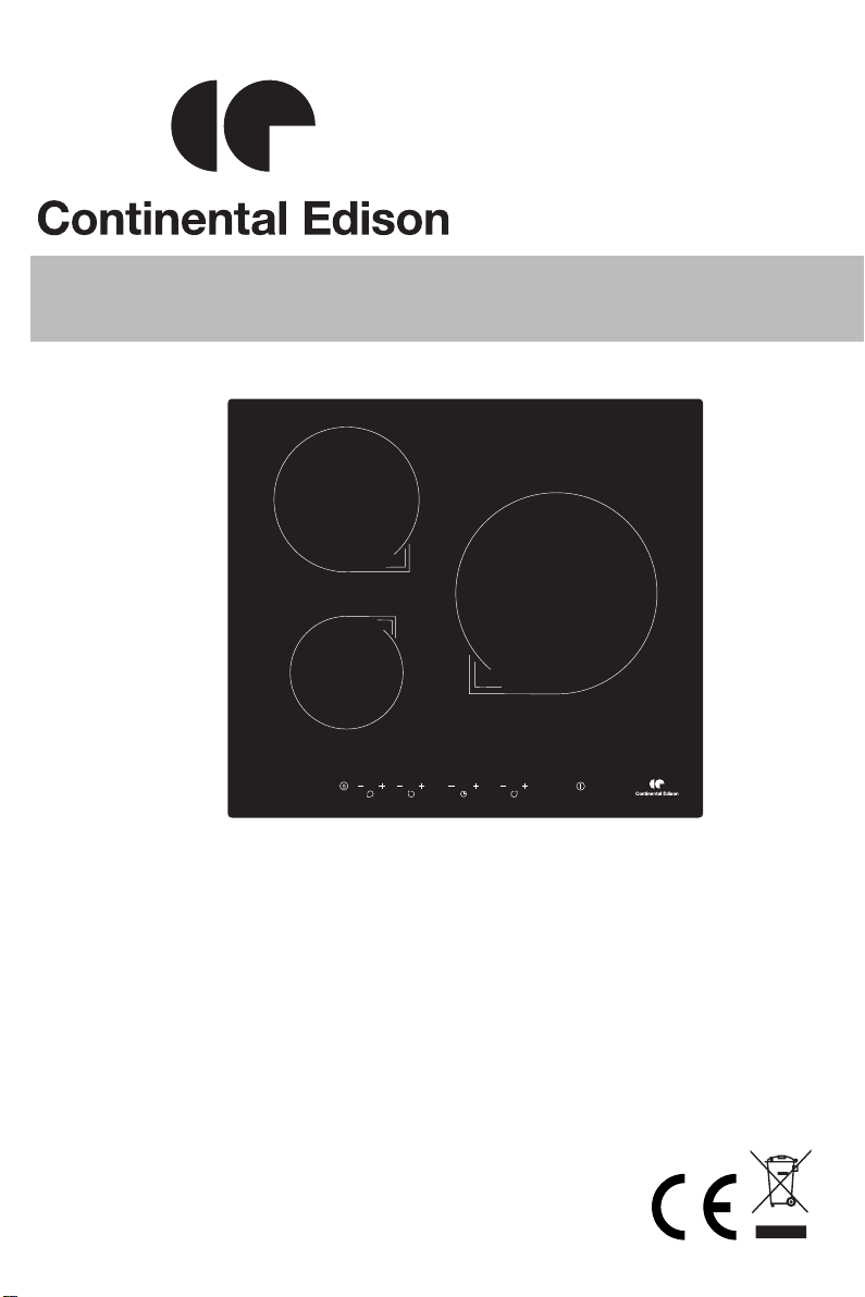
Cooking Hob
CECP551FSA
Cooking Zones INDUCTION
Supply Voltage
220-240V 50/60 Hz
400 V 50/60 Hz
Installed Electric Power
(W)
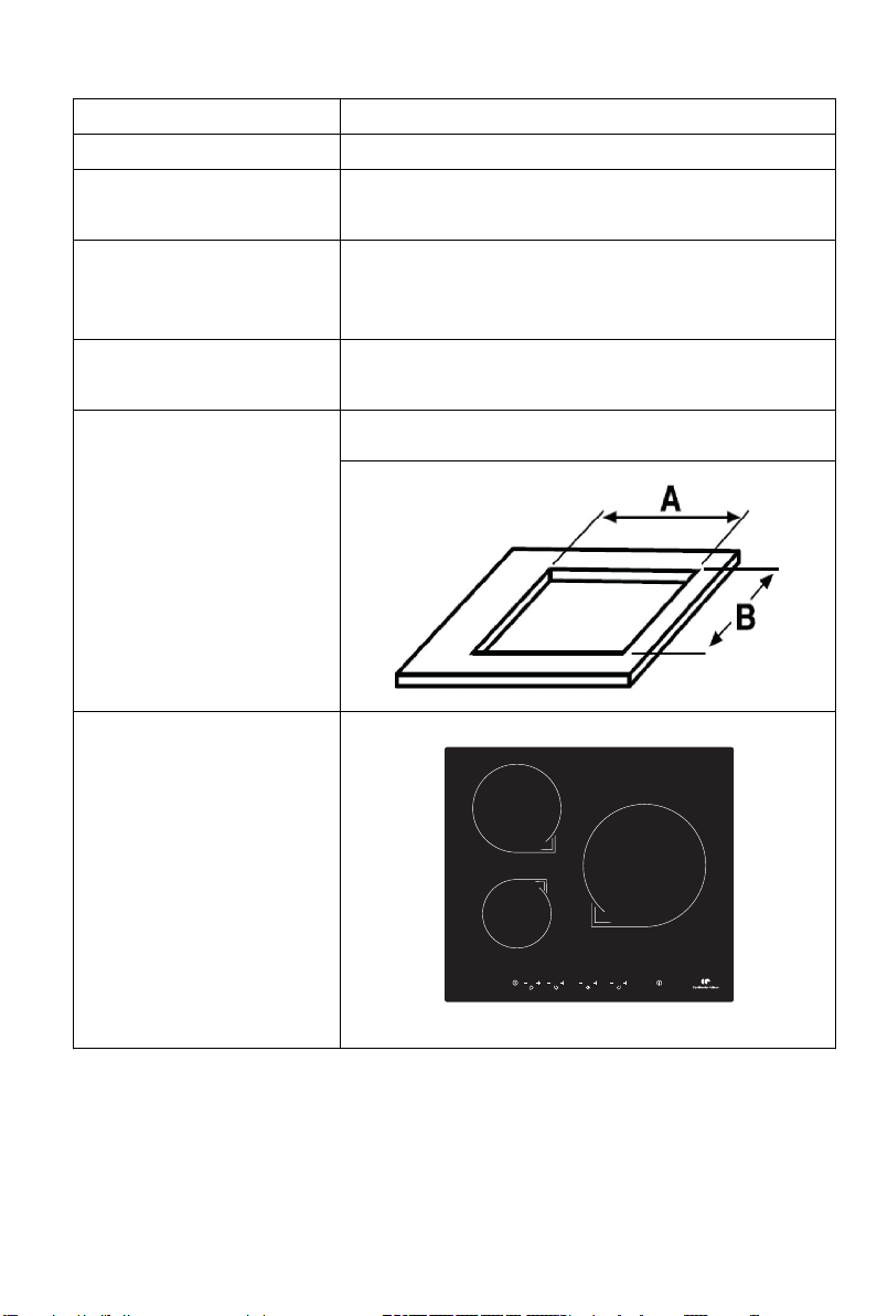
Product Size
D×W×H(mm)
Building-in Dimensions
A×B (mm)
Induction Hotplate
pearance
Ap
5500
590×520×55
560×490
2
Page 3
Dear customer:
Thank you for purchasing the the induction hotplate our product can
serve you many years to your satisfaction.
Please read this instructions manual carefully before using and
installation, keep it cautiously after reading for future reference.
Thank you for your purchase of the induction hotplate again, and wish
you to enjoy the pleasure by it.
Product Introduction
The induction hotplate can meet various demands of cuisine by
electromagnetic heating, with micro-computerized control and multifunction,
really the optimal choice for modern families.
The induction hotplate centers on customers and adopts personalized design,
and which will make your life comfortable and enabling to fully enjoy the
pleasure of life.
We have designed this hob for private use in home.
Working Principle
The induction hotplate is mainly composed of an induced heating coil, hotplate
made of ferromagnetic materials and control system.
In principle, current generates a powerful magnetic field via the coil. Large
numbers of vortexes are produced in the way that the magnetic lines in the
field contact the bottom containing iron or stainless steel substances. The
tremendous energy generated by the vortexes can heat the food directly by
converting efficiency heat energy penetrating through the bottom.
3
Figure (1)
Page 4

Over- Temperature Protection
A temperature sensor equipped can monitor the temperature inside the
hotplate. When an excessive temperature is monitored, the induction hotplate
will stop operation automatically.
Pot Detection
When an unsuitable size or non-magnetic pot (e.g. Aluminum), or some other
small item (e.g. knife, fork, key) has been left on the hob, or the pot has been
removed, the hob can stop heating immediately. If there is no suitable pan put
on the right hob in one minute, the hob will go automatically into the standby
state, and the buzzer will sound for warning at one time.
Heat Indication
When the hotplate is used for a long time, waste heat remains in the heating
zone in a few minutes. The code “H” appears, warning to be away from the
heating zone.
Protection of Shutting Down Automatic
Shutting down Automatic is a safety protection function for your induction
hotplate. It will shut down automatically if you forget to turn off your cooker.
The default working times for various power levels are shown in the
following table:
Power level
The heating zone shut down automatically
after
1~3 8 hours
4~6 4 hours
7~9 2 hours
*Remind:
The patient with a heart pacemaker shall use this product under the guidance
of the doctor.
4
Page 5
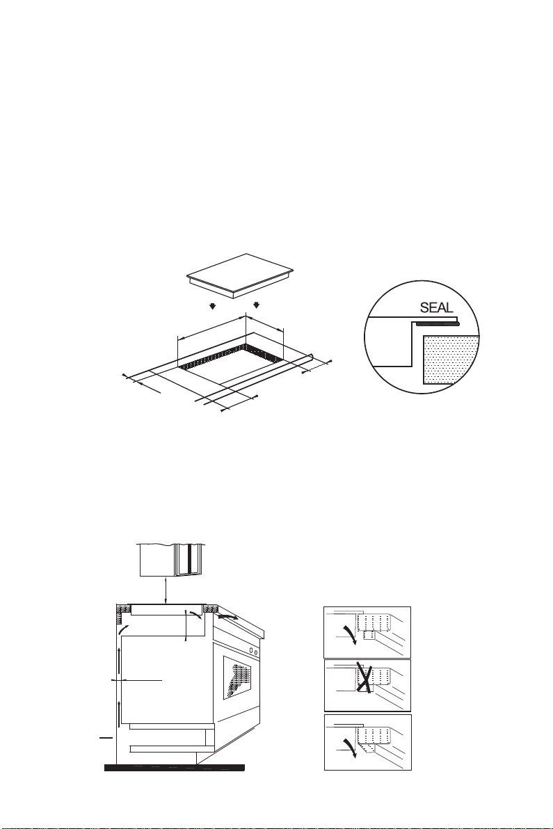
Selection of installation equipment
Drill holes on the table surface according to the sizes shown in the drawing.
For the purpose of installation and use, a minimum of 50 mm space shall be
preserved around the hole.
Be sure the thickness of the table surface is at least 30mm. Please select
heat-resistant table material to avoid larger deformation caused by the heat
radiation from the hotplate.
As shown in Figure (2)
49
c
m
ini
m m
5c
ni
i
m m
5c
Figure (2)
5 c
m mini
m
c
56
Under any circumstances, make sure the induction hotplate is well ventilated
and the air inlet and outlet are not blocked.
Ensure the induction hotplate is in good work state.
As shown in Figure (3)
mini 760mm
Air exit
mini 5 cm
mini 2 cm
Air intake
5
mini 5 mm
Figure (3)
Page 6
Note: The safety distance between the hotplate and the cupboard above the
hotplate should be at least 760mm.
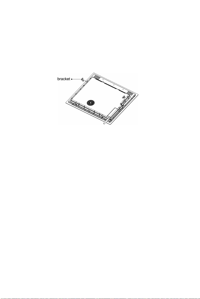
Fix the hob on the table by screw four brackets on the bottom of hob (as
shown in figure (4)) after installation. Adjust the bracket position to suit for
different table top thickness.
Figure (4)
Cautions:
1. The induction hotplate must be installed by qualified personnel or
technicians. We have professionals at your service. Please never conduct
the operation by yourself.
2. The induction hotplate shall be installed such that better heat radiation can
be ensured to enhance its reliability.
3. The wall and induced heating zone above the table surface shall withstand
heat.
4. To avoid any damage, the sandwich layer and adhesive must be resistant to
heat.
ELECTRICAL CONNECTION
"The installation must conform to the standard directives."
The manufacturer declines all responsibility for any damage that may be
caused by unsuitable or unreasonable use.
6
Page 7

Warning
• Always check before any electrical operation, the supply tension shown on
the electricity meter, the adjustment of the circuit breaker, the continuity of the
connection to earth to the installation and that the fuse is suitable.
• The electrical connection to the installation should be made via a socket with
a plug with earth, or via an Omni-pole cut-out switch with an opening gap of at
least 3 mm.
If the appliance has a socket outlet, it must be installed so that the socket
outlet is accessible.
• The yellow/green wire of the power supply cable must be connected to the
earth of both power supply and appliance terminals.
• The manufacturer cannot be held responsible for any accidents resulting
from the use of an appliance which is not connected to earth, or with faulty
earth connection continuity.
• Any queries regarding the power supply cord should be referred to After
Sales Service or a qualified technician.
• I f the cable is damaged or to be replaced, the operation must be carried out
the by sale agent with dedicated tools to avoid any accident.
Power line connection
The socket shall be connected according to the relevant standard or
connected to a single-pole breaker.
The method of connection is shown in Figure (5):
blue
grey
green-yellow
N2 N1 L2 L1
220-240V
PE
connet to the main power supply
220-240V 2+2N~
brown
220-240V
black
7
blue
grey
black
green-yellow
PE
connet to the main power supply connet to the main power supply
brown
N L2 L1
400V
220-240V
220-240V
400V~ 2-N
blue
green-yellow
PE
220-240V~
grey
N L
220-240V
brown
black
Figure (5)
Page 8
If the cable is damaged or needed to be replaced, the operation must be
carried out by the after-sale agent with dedicated tools to avoid any accidents.
If the appliance is being connected directly to the mains an Omni-polar
rcuit-breaker must be installed with a minimum opening of 3mm between
ci
ntacts.
co
The installer must ensure that the correct electrical connection has been made
and that it is compliant with safety regulations.
The cable must not be bent or compressed.
The cable must be checked regularly and replaced by authorized technicians
only.
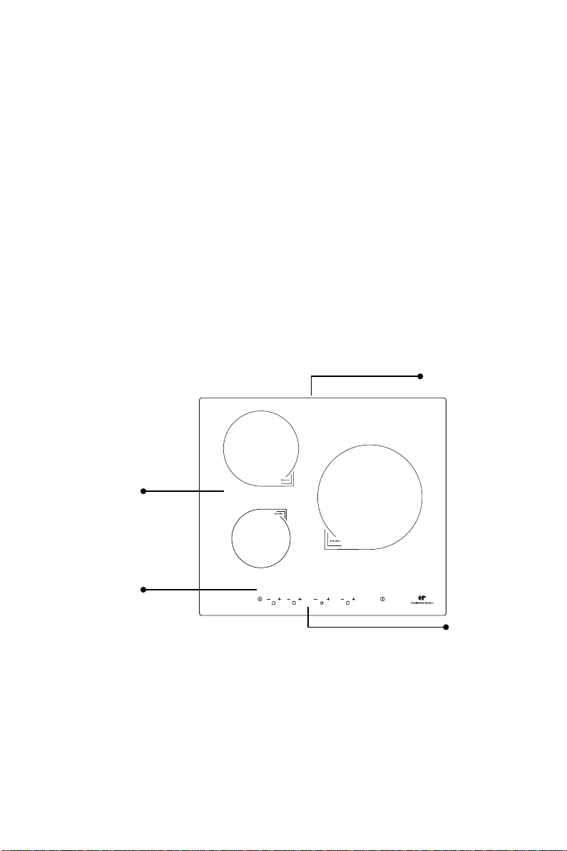
Induction Hotplate Appearance
Air entry
2
Ceramic plate
Control panel
8
3
1
Air vent
Figure (6)
Page 9
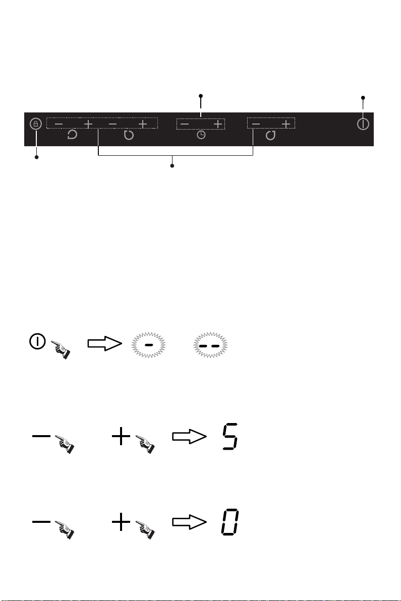
Schematic Diagram of The Control Panel
Lock
Timer Regulating key
Power Regulating key
gure (7)
Fi
On/OFF
Instructions For Use
Preparation Before Using:
After power on, the buzzer beep once, all the indicators light up for 1 second and
then go out, which indicates the induction hotplate enters the state of standby.
Put the pot in the center of the heating zone.
Operation Instructions:
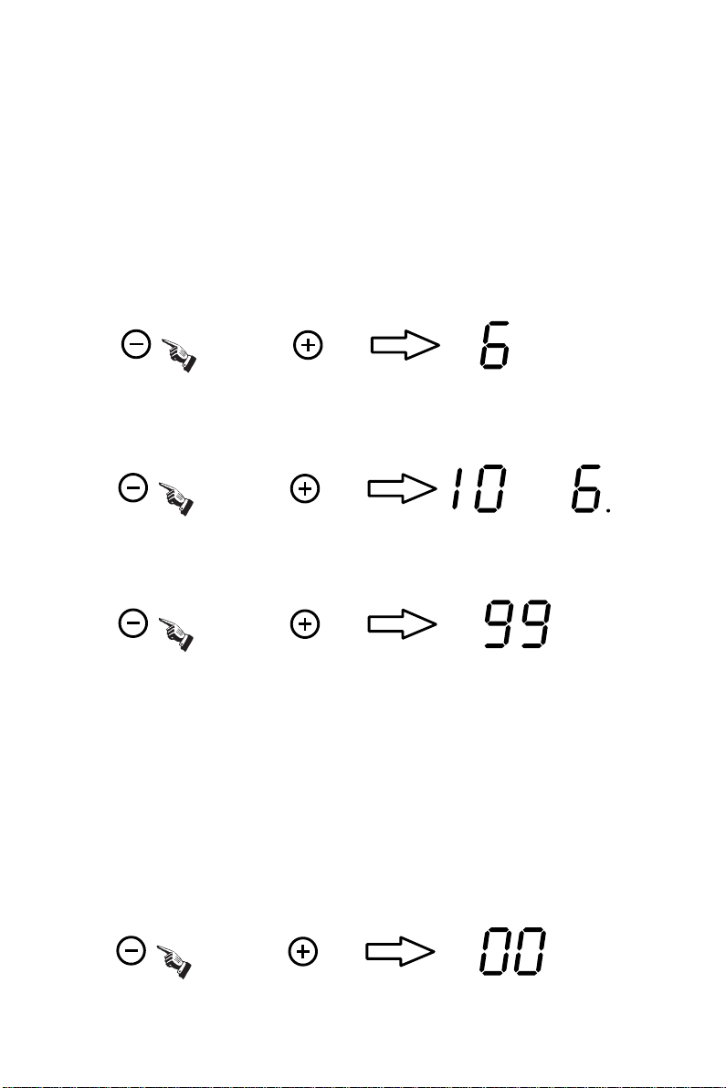
When the “ON / OFF” button is pressed, all the indicators show "-" .
OR
According to the heating zone where the pot is placed, press the "+" or "-"
button, select a relevant zone ,the indicator displays 5, then adjust the power
levels using the "+" or "-" button.
OR
Or press the "+" and "-" buttons simultaneously, the power setting immediately
chang to 0, and all the cooking zone switch off.
AND
9
Page 10
See the attached table “the max. power of each heating zone” for the power
specific to each heating zone.
Note: 1. After the “ON/OFF” button is pressed, the induction hotplate will
restore to its standby state if no any operation is carried out within one minute.
Timing function
Select the relevant cooking zone, and set the power level with the “+” or “-”
button. (e.g. the cooking zone 3 with power level 6)
OR
Press the "+"or"-""of timing button, the timing indicator flashes, and you can
set the timer at this point.
OR AND
Using the “+” or “-“of timing buttons, you can realize the setting of timing from
1 to 99 minutes.
OR
When the “+”of timing button is pressed, the time setting will increase by 1 minute;
And it will increase by 10 minutes when the “+”of timing button is long pressed.
When the “-”of timing button is pressed, the time setting will decrease by 1 minute;
And it will decrease by 10 minutes when the “-”of timing button is long pressed.
Timing confirmation:
After selecting a set time, once the timing indicator flashes for 5 seconds, the set
time will be confirmed to be valid automatically.
Timing cancellation:
If press the "+" and "-" simultaneously, the timing can be cancelled automatically,
with the timing indicator showing “0”.
AND
10
Page 11

Note:
1. In the timing state, the power level of the relevant cooking zone can be changed,
and the time set is still valid.
2. Press the “+” or “-“of timing button without select one cooking zone when the
induction hotplate is working, the time-warning function will operate. And the
warning time can be set just like the timing function. The buzzer will be beeping
for 30 seconds when the time is reached. The function will be cancelled when
the time is set to 0.
3. the time-warning function will be cancelled when the induction hotplate is
switched off.
Interlock Function:
To ensure the safety of children, the induction hotplate is provided with the function
of interlock.
Interlock:
Press the “Interlock” button, then the induction hotplate enters the locking state,
with the timing indicator showing “Lo”.
Unlock:
Holding the “Interlock” button for about 3 seconds, the locking state will be removed.
Note:
1. The rest buttons disabled except the “ON/OFF” and “Interlock” button when the
induction hotplate is in the locking state. Only unlocking the buttons or else the
induction hotplate won’t be operated.
2. If the induction hotplate enters the locking state in the off mode, the timing
indicator showing “Lo” for one minute. And it will be shown for one minute again
when the “ON/OFF” or “Interlock” button is pressed.
The max. power of each heating zone are as follows
Heating Zone
1 1500 10mm
2 20
3 250mm
The above power may vary if the material or the size of pot is differet.
Power(W)
Dia. Of the Heating Zone
00 180mm
2000
11
Page 12

Selection of heating appliances
Iron oil frying pan Stainless steel pot Iron pan Iron kettle
Enamel stainless
eel kettle
st
Enamel cooking
utensil
Iro
n plate
You may have multiple appliances suitable for heating.
This induction hotplate is able to identify multiple heating appliances, and you
n test them according to one of the following methods:
ca
1. Place the appliance in the heating zone. If the corresponding heating zone
lays a power level, it shows the suitability of the appliance; if “
disp
” flashes, it
shows the appliance does not fit in the induction cooking.
2. Have a magnet to contact the appliance. If there is attraction between them,
it shows the appliance also fits in the induction cooking.
● Requirement for pot material: the bottom contains materials of magnetic
co
nductivity.
● Requirement for shape: flat bottom.
Safety Reminding and Maintenance:
Please use a dedicated
power protection air
switch;
Indoor use only. Never directly wash the
in
duction hotplate with
water so as to avoid
dangers.
1
Page 13

appliance to avoid the
Never have the induction
hotplate to work without
food inside, otherwise its
operational performance
may be affected and
danger may happen.
We suggest that you
should periodically check
that there are no object
(glass, paper, etc) that
could obstruct the inlet
under your induction
hotplate.
For sealed food such as
canned goods, please
do not heat them before
opening their covers so
as to avoid any dangers
of explosion due to
heating expansion.
Metallic objects such as
knives, forks,spoons
and lids should not be
placed on the hotplate
since they can get hot.
After being used for a
long time, the
corresponding heating
zone of the induction
hotplate is till hot. Never
touch the ceramic
surface to avoid
burning.
Never use the induction
hotplate in high
temperature
environments such as
near a gas stove or
kerosene stove.
Do not put any
detergents or flammable
materials in the
equipment installed
under the induction
hotplate.
13
Do not place rough or
uneven appliances,
which may damage the
ceramic surface.
If the surface is
cracked, swith off the
possibility of electric
shock.
Page 14

Clean the induction
hotplate on a regular
basis to prevent foreign
matters from entering the
fan thus influencing the
normal operation.
DISPOSAL: Do not
dispose this product
as unsorted municipal
waste. Collection of
such waste separately
for special treatment is
necessary.
Keep electrical
appliance out of reach
from children or inform
person. Do not let them
use the appliances
without supervision.
If the supply cord is
damaged , it must be
replaced by the
manufacturer, its
service agent or
similarly qualified
persons in order to
This appliance is labeled in compliance with European
directive 2002/96/EC for Waste Electrical and Electronic
Equipment (WEEE). By ensuring that this appliance is
disposed of correctly, you will help prevent any possible
damage to the environment and to human health, which
might otherwise be caused if it were disposed of in the
wrong way.
The symbol on the product indicates that it may not be
treated as normal household waste. It should be taken to a
collection point for the recycling of electrical and electronic
goods.
This appliance requires specialist waste disposal. For
further information regarding the treatment, recover and
recycling of this product please contact your local council,
your household waste disposal service, or the shop where
you purchased it.
For more detailed information about treatment, recovery
and recycling of this product, please contact your local city
office, your household waste disposal service or the shop
where you purchased the product.
avoid a hazard.
14
Page 15

Cleanness and Maintenance
You can easily clean the surface of the induction hotplate if following
the methods given in the table.
Type of
contamination
Light
Accumulation of
dirt
Immerse in hot water then wipe it
dry
Immerse in hot water then wipe it
dry with abrasive sponge
Method of cleaning
Apply white vinegar to the
Rings and lime
crumbles
Sweetmeat, melt
aluminum or
plastics
polluted zone, then wipe it dry
with soft cloth or a special article
available in local markets
Use a scraper suitable for
ceramic glass (to protect glass, a
silicon product is preferred) to
remove residuals
Hint: please disconnect power before the cleaning.
Articles used
forcleaning
Cleaning sponge
Special cleaning
sponge for ceramic
glass
Special adhesive for
ceramic glass
Special adhesive for
ceramic glass
15
Page 16

Failure Display and Inspection
If an abnormality comes up, the induction hotplate will enter the protective
state automatically and display corresponding protective codes:
Troubles Possible reasons Solutions
F0-F2 Fan failure. Please contact the supplier
Power on, and then restart after the
F3-F8
F9-FE
Thermistor component
failure.
Temperature sensor of
the IGBT failure.
E3-E4 Abnormal temperature.
Bad hotplate heat
radiation.
The above are the judgment and inspection of common failures.
Please do not disassemble the unit by yourself to avoid any dangers and
damages to the induction hotplate.
temperature around returns to be
normal.
Please contact the supplier.
Power on, and then restart after the
temperature around returns to be
normal.
Please contact the supplier.
Please inspect whether power
supply is normal. E1-E2 Abnormal supply voltage.
Please contact the supplier.
Please inspect the pot.
Please restart after the hotplate
cools down.
Please contact the supplier.
Please restart after the hotplate
cools down. E5-E6
Please contact the supplier.
16
Page 17

Customer Care Service
Before calling the After Sales Service
In case the appliance should not work correctly we suggest to:
-verify if the plug is correctly inserted in the socket
-read the Failure and Display table above
In case it is not possible to establish the reason for the bad functioning of the
appliance, switch it off, do not try to manumit it and call the After Sales Service.
Special DecIaration
All the contents in this material have been subjected to careful check. For any
mistake and omission in printing or misunderstanding of the contents,the
company keeps the right of interpretation.
With a view to constantly improving our products, we reserve the right to make
any changes to the technical, program or aesthetic features connected with
the technical evolution.
Addition:any technical improvement will be placed in the revised manual
without notice;for product appearance and color is according to the actual one.
17
Page 18

Cooking Hob
CECP551FSA
Cooking Zones 3 INDUCTION
Supply Voltage
220-240V 50/60 Hz
400 V 50/60 Hz
Installed Electric Power
(W)
Product Size
D×W×H(mm)
Building-in Dimensions
A×B (mm)
Induction Hotplate
Appearance
5500
590×520×55
560×490
18
Page 19

?YVc ?]ZV_e.
leki h[c[hY_edi Z[ deki Wle_h \W_j Yed\_WdY[ fekh b-WY^Wj
Meki
Z[ Y[jj[ jWXb[ _dZkYj_ed
hvfedZh[ r lei [n_][dY[i3
jekj[
kj_b_iWj_ed [j Yedi[hl[p2b[
Yedikbj[h kbjvh_[kh[c[dj [d YWi Z[ X[ie_d3
KbMJE 1kd
K_i[p Wjj[dj_l[c[dj
fheZk_j vjkZ_v fekh leki iWj_i\W_h[
ie_]d[ki[c[dj
D_ec`UfTeZ`_
[j
Y[ ceZ[ Z{[cfbe_ WlWdj
Z[ \Wted r fekle_h b[
KW jWXb[ Z[ Yk_iied _dZkYj_ed [ij kd WffWh[_b ceZ[hd[1
izh [j f[h\ehcWdj
]hsY[ r b-vd[h]_[ vb[YjhecW]dvj_gk[
Kehi Z[ iW YedY[fj_ed1 deki Wledi Wffehjv kd[ Wjj[dj_ed fWhj_Ykb_uh[ r bW
i_cfb_Y_jv Z{kj_b_iWj_ed
gk_ fheYkh[ Z{[nY[bb[dji hvikbjWji fekh jeki b[i jof[i Z[
[j r bW \_WX_b_jv Z[ Y[jj[ jWXb[ Z[ Yk_iied3
CECP551FSA
[j kd ioijuc[ Z[ YeccWdZ[ vb[Yjhed_gk[3
Yk_iied
Figure (1)
19
Page 20

oL
’l
cenu’uqsr
.
etunim
edeloressa
xuenimulruetacidni
»«
eétpadanielliat
of,uaetuoc(selisnetsustitepsertua
ciffa’s
mn
onuo
ténga
ossiuc
edenozalteareh
:elpmexe(euqi
resn
uo
)muinimula
,nossiucedenozalruséssialététno)élc,ettehcru
1sèrpaeévitcaséda
sruoh 8 3~1
sruoh 4 6~4
sruoh 2 9~7
.etunimenu’dtuobuatnieté’stetnemetaidémmireffuahcedetêrra’seuqalp
alteehciffa’s»«xuenimulruetacidni’l,euqalpaledeéritertseelisnetsu’leuqsroL
Cetappareiln'estpasprépasprévupourêtreutilisépardespersonnes(ycomprislsenfants)
don’tlescapacitésphysiques,sensoriellesoumentalessontréduites,oudespersonnes
dénuéesd'expérienceoudeconnaissance,saufsiellesontpubénéficier,parl'intermédiaire
d'unepersonneresponsabledeleursécurité,d'unesurveillanceoud'instructionspréalables
concernantl'utilisationdel'appareil.
Nepasutiliserd'appareildenettoyageàlavapeur
20
Page 21

49
c
m m
m
ni
i
m m
5c
ni
i
m
c
56
5
c
m m
i
ni
5c
Figure (2)
3
mini 5 cm
mini 2 cm
mini 5 mm
Figure (3)
21
Page 22

Figure (4)
22
Page 23

5
e
n
u
s
a
i
r
J
t
G
r
e
V
N2 N1 L2 L1
220-240V
PE
Connectez à l’alimentation principale
220-240V 2+2N~
u
e
l
B
Marron
220-240V
r
i
o
N
e
n
u
u
a
e
J
l
t
B
r
e
V
N L2 L1
PE
220-240V
Connectez à l’alimentation principale
400V~ 2-N
s
i
r
G
220-240V
Marron
400V
r
i
o
N
Figure (5)
e
n
u
u
a
e
J
l
t
B
r
e
V
N L
PE
220-240V
Connectez à l’alimentation principale
220-240V~
r
s
i
i
r
o
G
N
Marron
23
Page 24

2
3
1
Figure (6)
Schéma du tableau de commande
Touche de sélection de zone de chauffage
Touche Minuteur
Clé (Dispositif sécurité)
Touche de réglage
Figure (7)
Marche/arrêt
24
Page 25

Mode d'emploi
Préparation avant utilisation:
Après avoir allumé les plaques, le signal sonore sonnera une fois et tous
voyants s’allumeront pendant 1 seconde puis s’éteindront, ce qui indique
la touche des plaques entre en état de veille.
Instructions de fonctionnement
Lorsque vous appuyez sur la touche Marche/arrêt, tous les indicateurs
affichent -» ou «---»
OU
les
que
En fonction de la zone de chauffage sur laquelle est placée la casserole,
choisissez la zone de sélection correspondante (par ex., la zone 1).
appuyez sur la touche "+" et "-" simultanément sur les touches
OU
Si vous appuyez sur les touches « + » et « - » simultanément, la
puissance revient automatiquement à zéro et la zone de cuisson
s’éteint.
AND
Veuillez consulter le tableau indiquant la puissance maximale pour
chaque zone de cuisson pour connaître la puissance spécifique à
chaque plaque de cuisson !
Remarque : 1. Un fois que vous avez appuyé sur le bouton
« MARCHE/ARRET », les plaques chauffantes à induction se
remettront en état de veille si aucune action n’est entreprise en l’espace
d’une minute.
Fonction Minuterie:
Sélectionnez la plaque de cuisson choisie, et réglez la puissance avec la
touche
« + » ou « - ».
OU
25
Page 26

Appuyez sur le bouton « Minuterie », l’indicateur de minuterie clignote, et
vous pouvez alors
régler la minuterie à ce moment-là.
OU
Appuyez sur le boutton « + » et « - », vous pouvez régler les paramètres
du minuteur de 0 à 99 minutes.
OU
Lorsque vous appuyez sur la touche « + », le temps de minuterie
augmentera par paliers
la touche, le temps
d’1 minute. Si vous maint
augmentera alors par paliers
ssion est maintenue encore plus longtemps.
touche « - », le temps de minuterie diminuera
maint
par paliers de 10 minutes, si
enez la pression sur la touche, le temps
la pression est maintenue encore plus
Lorsque vous appuyez sur la
par paliers
enez la pression sur
de 10 minutes, si la pre
d’1 minute. Si vous
diminuera alors
longtemps.
Timing confirmation:
Confirmation de la minuterie
Après avoir sélectionné un temps de minuterie, laissez l’indicateur de
minuterie clignoter pendant
touche « Minuterie » pour confirmer le
5 secondes, ou appuyez sur la
temps choisi. La minuterie
sera alors automatiquement confirmée.
Annulation de la minuterie
Si vous appuyez simultanément sur les touches « + » et « - », la
minuterie sera
affichera alors
automatiquement annulée et l’indicat
« 0 ».
26
eur de minuterie
Page 27

Remarque :
1. Lorsque la minuterie
est enclenchée, il est possible de
changer la
puissance de cuisson, le temps de minuterie restera valide.
2. Appuyez sur le bouton de minuterie "+" ou "-" sans avoir sélectionné
une plaque de cuisson
fonction d’alarme sera
comm
e pour le réglage de la minuterie. Le
secondes à l’heure d’alar
le temps
est atteint.
alors que la plaque à induction est allumée, la
accessible. Pour régler
me voulue. Cette fonction sera
l’alarme, procédez exactement
buzzer sonnera
pendant 30
annulée lorsque
3. Lorsque la plaque à induction est éteinte, la fonction d’alarme sera
désactivée.
Fonction Sécurité enfants :
Afin de garantir la sécurité des enfants, la plaque à induction possède
une fonction de verrouillage.
Verrouillage sécurité enfant
pour que la plaque à
Appuyez sur le bouton « Sécurité enfant »
induction passe en mode
verrouillé. L’indicateur de
minuterie affiche alors « Loc ».
Dévérrouillier:
Tenir le "verrouillage" pendant environ 3 secondes, l'état de blocage
sera
supprimée.
Note:
1.Le touches restantes sont désactivées, sauf pour
« MARCHE/ARRET » et « Verrouillage » lorsque la plaque à induction
est en mode verrouillé. Il est nécessaire de déverrouiller la sécurité
enfant pour faire fonctionner la plaque.
2.Si la plaque à induction est mise en mode « sécurité enfant »
alors qu’elle est éteinte, l’indicateur de minuterie affiche « Lo »
pendant 1 minute. Lorsque vous appuyez sur le bouton
« MARCHE/ARRET » ou « Sécurité enfant », le même affichage
apparaîtra aussi pendant 1 minute.
27
Page 28

Fonction Réchauffer :
Heating Zone
1 1500 140mm
2
3 250mm
Power(W)
Dia. Of the Heating Zone
2000 180mm
2000
28
Page 29

29
Page 30

30
Page 31

31
Page 32

F0 -F2
F3-F8
F9 -F
E1 /E 2
E 3/ E4
E 5/ E6
E
IGBT
32
Page 33

33
 Loading...