

CONTINENTAL CONTROL SYSTEMS WattNode BACnet Series, WattNode Revenue Series, WattNode Plus Series, WattNode Logger Series, WNC-3Y FT10 Series Installation Manual
...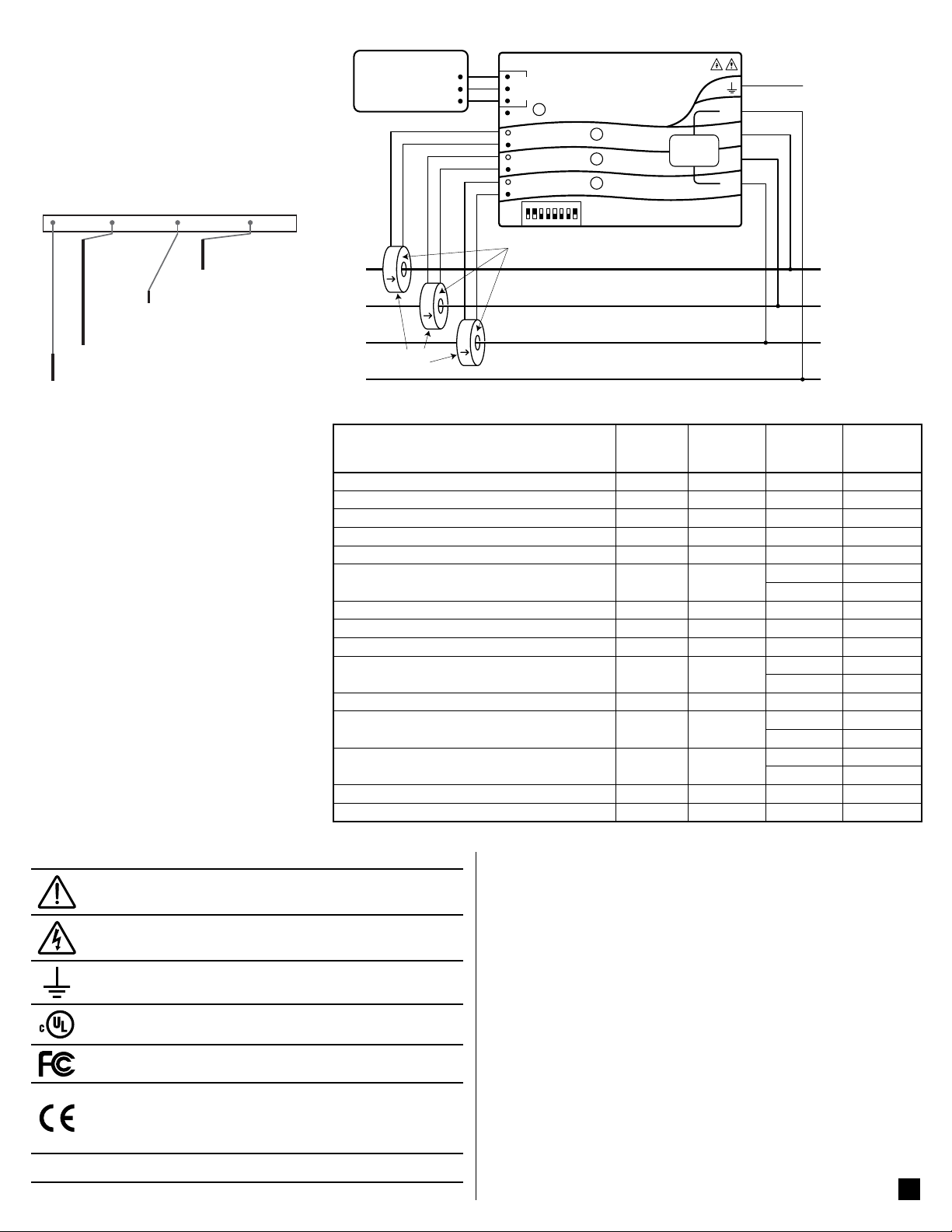
Ground
WHITE
BLACK
ØB CT
ØC CT
ØA CT
ØB
ØC
N
ØA
Common
B+, D1, RxD+/TxD+
EIA-485
PC or BACnet Host
A−, D0, Rx D−/ TxD−
Continental Control Systems LLC
Status
Status
Status
X
C
B
+
A
-
MS/TP
Com
WNCWNC-
W
ATTNODE
®
BAC
NET
-BN
-BN
Neutral
Phase A
Phase B
Phase C
LOAD
WHITE
BLACK
WHITE
BLACK
LINE
Source
Faces
Current
Transformers
3Y-xxx
3D-xxx
WattNode
Series - Service - Interface Options
RWNC = Revenue, third generation
®
BaCNet
and
WattNode® ReveNue
Electric Power Meter
Installation Manual
______ - _______ - ________
3Y-208
3Y-400
3Y-480
3Y-600
3D-240
BN = BACnet
3D-400
3D-480
WNC = Third generation
See website
for options
®
1 Precautions
1.1 Only qualified personnel or licensed electricians should inst all the Wat tN ode me ter. The
mains voltages of 120 to 600 Vac can be lethal!
1.2 Follow all applicable local and national electrical and safety codes.
1.3 T he termina l block sc rews are not insulated.
Do not cont ac t met al too ls to th e sc rew ter mi nals if the circuit is live!
1.4 Veri fy that circui t voltages and cur rents are
within the proper range for the meter model.
1.5 Us e only UL liste d or UL reco gnized curr ent
transformers (CTs) with built-in burden resistors, that generate 0.333 Vac (333 millivolts AC)
at rated cur rent. Do not u se curr ent out put
(ratio) CTs such as 1 a mp or 5 a mp ou tpu t
CTs: they will des troy the me ter and ma y
create a shock hazard.
1.6 Protect the line voltage inputs to the meter with
fuses or c ircuit breake rs (not needed for t he
neutral or ground wires). See 3.3.1 below.
1.7 Equipment must be disconnected from the
HAZARDOUS LIVE voltages before access.
1.8 If the meter is not installed correctly, the safety
protections may be impaired.
Figure 1: WattNode Wiring Diagram
Electrical
Service (or Load) Types
1 Phase 2 Wire 120V with neutral 96 – 138 n.a. 3Y-208 N and ØA
1 Phase 2 Wire 230V with neutral (non-U.S.) 184 – 264 n.a. 3Y-400 N and ØA
1 Phase 2 Wire 277V with neutral 222 – 318 n.a. 3Y-480 N and ØA
1 Phase 2 Wire 208V no neutral n.a. 166 – 276 3D-240 ØA and ØB
1 Phase 2 Wire 240V no neutral n.a. 166 – 276 3D-240 ØA and ØB
1 Phase 3 Wire 120V/240V with neutral 96 – 138 166 – 276
3 Phase 3 Wire Delta 208V no neutral n.a. 166 – 276 3D-240 ØA and ØB
3 Phase 3 Wire Delta 400V no neutral (non-U.S.) n.a. 320 – 460 3D-400 ØA and ØB
3 Phase 3 Wire Delta 480V no neutral n.a. 384 – 552 3D-480 ØA and ØB
3 Phase 4 Wire Wye 120V/208V with neutral 96 – 138 166 – 276
3 Phase 4 Wire Delta 120/208/240V with neutral 96 – 138 166 – 276 3D-240 ØA and ØB
3 Phase 4 Wire Wye 230V/400V with neutral
(non-U.S.)
3 Phase 4 Wire Wye 277V/480V with neutral 222 – 318 384 – 552
3 Phase 4 Wire Delta 240/415/480V with neutral 222 – 318 384 – 552 3D-480 ØA and ØB
3 Phase 4 Wire Wye 347V/600V with neutral 278 – 399 480 – 690 3Y-600 N and ØA
Table 1: WattNode Models
Line-to-
Neutral
(Vac)
184 – 264 320 – 460
Line-to-
Line
(Vac)
WattNode
Service
Type
3Y-208 N and ØA
3D-240 ØA and ØB
3Y-208 N and ØA
3D-240 ØA and ØB
3Y-400 N and ØA
3D-400 ØA and ØB
3Y-480 N and ØA
3D-480 ØA and ØB
Meter
Powered
by
1.9 Symbols
V~
Read, understand, and follow all instructions including warnings
and precautions before installing and using the product.
Potential Shock Hazard from Dangerous High Voltage.
Functional ground; should be connected to earth ground if possible,
but is not required for safety grounding.
UL Listin g mark. This s hows the UL an d cUL (Canadia n) listing
mark.
FCC Mark. This logo indicates compliance with part 15 of the FCC
rules.
Complie s with t he regul ation s of the Euro pean Uni on for Pr oduct
Safety and Electro-Magnetic Compatibility.
• Low Voltage Directive – EN 61010-1: 2001
• EMC Directive – EN 61327: 1997 + A1/1998 + A2/2001
This indicates an AC voltage.
2 Overview
Congrat ulati ons on yo ur pur chas e of the Wat tN ode® BACnet® watt/ watt -hou r
transducer (meter). The WattNode mete r enables you t o make power and energy measurements within electric service panels avoiding the costly installation of subpanels and associated wiring. It is designed for use in demand side
management (DSM), submetering, and energy monitoring applications. The
WattNod e meter commun icates on an EI A RS- 485 two -wire bu s using the
BACnet protocol.
2.1 Additional Literature
See the Continental Control Systems, LLC website (www.ccontrolsys.com)
for product pages, datasheets, and support pages for all WattNode meter models and cur rent tr ansfor mers. E ach Watt Node m odel has a n Operating and
Reference Guide with detail ed inform ation on th e available mea surements
and interface.
2.2 Electrical Service Types
Tab l e 1 a bove lists the Wat tNode m odels and c ommon ci rcuit ty pes. In the
“Elect ric al Ser vi ce Types” col umn, whe n two vol tage s are liste d with a s lash
between them, they indicate the line-to-neutral / line-to-line voltages. The
“Line-to -Neutral” and “Line -to-Line” columns show the operating ranges for
the WattNode meters.
1
Connect the line voltages to the meter inputs as shown in the following figures
Ground
Ground
Ground
Ground
Ground
Ground
for each service type. See Figure 1 above for an overview.
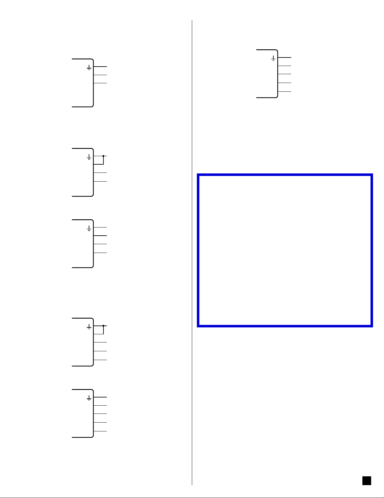
2.2.1 Single-Phase Two-Wire with Neutral
This is a co mm o n re si d ent ia l an d b ra nc h c i rc ui t c o nn ec t i on . Up to t h re e su ch
circuits may be monitored with one meter by also using the ØB and ØC inputs.
W
ATT
N
N
ØA
ODE
ØB
®
ØC
2.2.2 Single-Phase Two-Wire No Neutral
This circuit occurs in residential (commonly 120/240 Vac) and some commercial
applications. The meter is powered from the ØA and ØB terminals. We recommend connecting the N terminal to ground to provide a clean voltage reference
for the measurement circuitry (no current will flow through this terminal).
Neutral
Line
W
ATT
N
N
ØA
ODE
ØB
®
ØC
2.2.3 Single-Phase Three-Wire with Neutral
This is a common residential service at 120/240 Vac.
L1
L2
W
ATT
N
N
ØA
ODE
ØB
®
ØC
2.2.4 Three-Phase Three-Wire Delta No Neutral
This is co mmon in comm ercial and in dustrial se ttings. In s ome cases, t he
service may be four-wire, wye but the load may only be three wire (no neutral).
Occasionally, a load will only be connected to two of the three lines (say L1 and
L2). For this case, connect the two active lines to the ØA and ØB terminals and
connect two CTs for the two lines.
Neutral
L1
L2
W
ATT
N
N
ØA
ODE
ØB
®
ØC
2.2.5 Three-Phase Four-Wire Wye with Neutral
This is a common commercial and industrial service.
L1
L2
L3
W
ATT
N
ODE
N
ØA
ØB
®
ØC
Neutral
L1
L2
L3
the high le g of a four-w ire th ree - phas e delt a ser v ic e to be lab ele d as the “ C”
phase instea d of the “ B ” pha se. The Wat tN od e meter w ill wo rk c or rec tly w ith
the high-leg connected to ØA, ØB, or ØC.
See the web article Four Wire Delta Circuits for more information.
W
ATT
N
N
ØA
ODE
ØB
®
ØC
2.2.7 Grounded Leg Service
In rare cases with delta services or single-phase two-wire ser vices without
neutral, one of the phases may be grounded.
The WattNode meter will correctly measure services with a grounded leg, but
the measur e d vo l t a g e a n d p o we r f o r t h e g r o u n d e d p h a s e w i l l b e ze r o a n d t h e
status LEDs (if present) will not light for the grounded phase, because the voltage is near zero. Also, this type of service may result in unusual power factors.
See the web article Grounded Leg Services for more information.
3 Installation
3.1 Installation Checklist
See the sections referenced below for installation details.
□
Mount the WattNode meter (see 3.2).
□
Turn off power before making line voltage connections.
□
Connect circuit breakers or fuses and disconnects (see 3.3.1).
□
Connec t th e lin e volt a ge w ire s to t he met er ’s gre en te rm ina l bl oc k (see
3.3.2).
□
Mount the CTs around th e li n e c o n du c to r s . M ake su re t h e CTs face th e
source (see 3.4).
□
Connec t the twis ted white and bla ck wires fr om the CTs to the black
terminal b lock o n the meter, matchi ng the wi re col ors to th e white and
black dots on the meter label (see 3.4.1).
□
Check that the CT phases match the line voltage phases (see 3.4).
□
Record t he CT r ate d c u r re nt f or e ac h m ete r, becau se i t w il l be r eq ui re d
during commissioning.
□
Connec t the out put ter minals o f the Watt Nod e meter to th e monit orin g
equipment (see 3.5).
□
Check tha t all th e wi res ar e sec ur ely in sta lle d in th e ter min al bl oc ks by
tugging on each wire.
□
Apply power to the meter.
□
Verify that the LEDs indicate correct operation (see 4.2, 4.3).
3.2 Mounting
● Protect th e me ter f r o m te mp er at ur e s be l ow –30°C (-2 2 ° F) o r a bove 5 5° C
(13 1°F), excessive moisture, dust, salt spray, or other contamination, using
a NEMA rated enclosure if necessary. The meter requires an environment
no worse than pollution degree 2 (normally only non-conductive pollution;
occasionally, a temporary conductivity caused by condensation).
● The meter must b e inst alle d in an el ec tri cal s er vi ce pa nel, an e ncl osure,
or a limited access electrical room.
● Do not use the meter as a dr illin g guid e; the dr ill c huck c an da mage t he
screw terminals and metal shavings may fall into the connectors.
The meter has two mounting holes spaced 136.6 mm (5.375 in) apart (centerto- center). Thes e mounting ho les are nor mally obsc ured by the detac hable
screw ter mina ls. Rem ove the sc rew te rmi nals t o mar k the h ole p osi tio ns and
mount the meter.
Self-tapping #8 sheet metal screws are included. Don’t over -tighten the screws,
as long-term stress on the case can cause cracking.
Neutral
L1
L2
L3
2.2.6 Three-Phase Four-Wire Delta with Neutral (Wild Leg)
The uncommon four-wire delta electrical service is a three-phase delta service
with a cent er-tap on one of t he transfo rmer wind ings to creat e a neutral fo r
single-phase loads.
The high-leg or phase with the higher voltage as measured to neutral has traditional ly b een d es ig nate d “ Ph ase B ”. A chang e to t he 2 0 0 8 N EC now al low s
3.3 Connect Voltage Terminals
3.3.1 Circuit Protection
The WattNode meter is considered “permanently connected equipment” and
requires a disconnect means (circuit breaker, switch, or disconnect) and overcurrent protection (fuse or circuit breaker).
2
 Loading...