

CONTINENTAL CONTROL SYSTEMS WNC-3D-240-MB, WNC-3Y-400-MB, WNC-3D-400-MB, WNC-3D-480-MB, WNC-3Y-600-MB Installation Manual
...
WattNode
®
Modbus
®
Electric Power Meter - Installation Manual
WattNode Modbus
Models
WNC-3Y-208-MB RWNC-3Y-208-MB
WNC-3Y-400-MB RWNC-3Y-400-MB
WNC-3Y-480-MB RWNC-3Y-480-MB
WNC-3Y-600-MB RWNC-3Y-600-MB
WNC-3D-240-MB RWNC-3D-240-MB
WNC-3D-400-MB RWNC-3D-400-MB
WNC-3D-480-MB RWNC-3D-480-MB
www.ctlsys.com
WattNode Revenue
for Modbus Models

Contents
1 Precautions ..............................................................................................................................3
1.1 Symbols .....................................................................................................................................3
2 Overview ...................................................................................................................................3
2.1 Additional Literature ...................................................................................................................3
2.2 Electrical Service Types ............................................................................................................4
3 Installation ................................................................................................................................7
3.1 Installation Checklist ..................................................................................................................7
3.2 Mounting ....................................................................................................................................7
3.3 Connect Voltage Terminals ........................................................................................................7
3.4 Connect Current Transformers ..................................................................................................8
3.5 Connect the Output Signals .......................................................................................................9
4 Operation ................................................................................................................................10
4.1 Initial Configuration ..................................................................................................................10
4.2 Power Status LEDs ..................................................................................................................10
4.3 Modbus Communication LED ..................................................................................................12
4.4 Monitoring ................................................................................................................................12
4.5 Maintenance and Repair ..........................................................................................................12
5 Specifications ........................................................................................................................12
5.1 Accuracy ..................................................................................................................................12
5.2 Measurement ...........................................................................................................................13
5.3 Electrical ..................................................................................................................................13
5.4 EIA RS-485 Interface ..............................................................................................................14
5.5 Certifications ............................................................................................................................14
5.6 Environmental ..........................................................................................................................15
5.7 Mechanical ...............................................................................................................................15
5.8 FCC Information .......................................................................................................................15
5.9 Warranty ...................................................................................................................................16
5.10 Limitation of Liability ................................................................................................................16
2
1 Precautions
● Only qualified personnel or licensed electricians should install the WattNode meter. The
mains voltages of 120 to 600 Vac can be lethal!
● Follow all applicable local and national electrical and safety codes.
● The terminal block screws are not insulated. Do not contact metal tools to the screw terminals
if the circuit is live!
● Verify that circuit voltages and currents are within the proper range for the meter model.
● Use only UL Listed or UL Recognized current transformers (CTs) with built-in burden resistors,
that generate 0.333 Vac (333 millivolts AC) at rated current. Do not use current output (ra-
tio) CTs such as 1 amp or 5 amp output CTs: they will destroy the meter and may create
a shock hazard.
● Protect the line voltage conductors to the meter with fuses or circuit breakers (not needed for
the neutral or ground wires). See 3.3.1 below.
● Equipment must be disconnected from the HAZARDOUS LIVE voltages before access.
● If the meter is not installed correctly, the safety protections may be impaired.
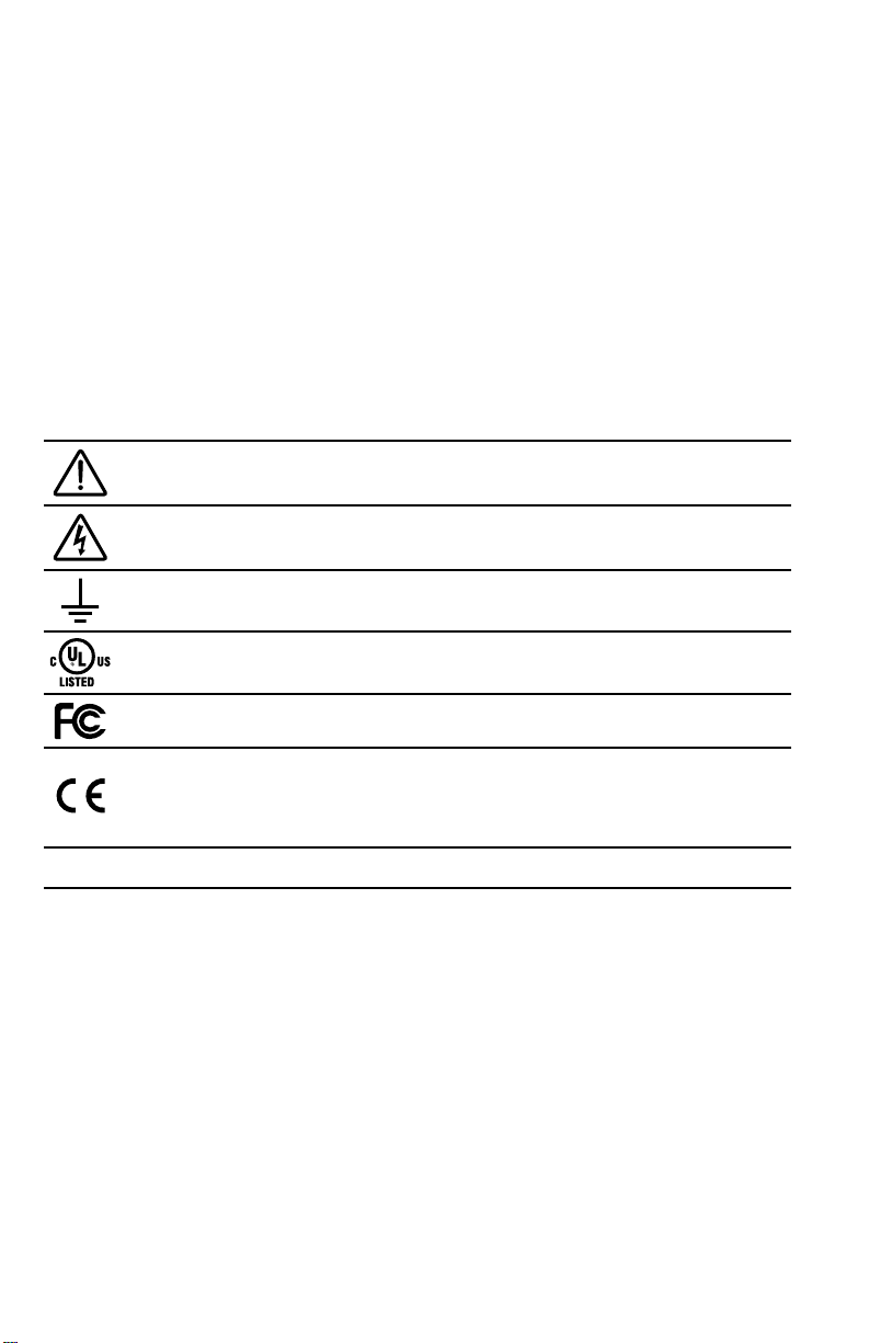
1.1 Symbols
Read, understand, and follow all instructions including warnings and precautions
before installing and using the product.
Potential Shock Hazard from Dangerous High Voltage.
Functional ground; should be connected to earth ground if possible, but is not
required for safety grounding.
UL Listing mark for U.S.A. and Canada.
FCC Mark. This logo indicates compliance with part 15 of the FCC rules.
Complies with the regulations of the European Union for Product Safety and
Electro-Magnetic Compatibility.
• Low Voltage Directive – EN 61010-1:2010 (3rd Edition)
• EMC Directive – EN 61326-1:2006
V~
This indicates an AC voltage.
2 Overview
Congratulations on your purchase of the WattNode® Modbus® or WattNode Revenue for Modbus
watt/watt-hour transducer (meter). It is designed for use in demand side management (DSM),
submetering, energy monitoring, billing and renewable energy applications. The WattNode meter
communicates on an EIA RS-485 two-wire bus using the Modbus RTU protocol.
The WattNode Revenue version meets the ANSI C12.1 standard for revenue metering when used
with IEEE C57.13 class 0.6 current transformers, such as the Accu-CT
independently certified by MET Laboratories and are listed on the California Solar Initiative (CSI)
site as approved for PBI use.
2.1 Additional Literature
See the Continental Control Systems, LLC website (https://ctlsys.com) for product pages,
datasheets, and support pages for all WattNode meter models and current transformers. Each
WattNode model has an Operating and Reference Guide with detailed information on the available measurements and interface.
3
®
. Certain models have been
Ground
WHITE
BLACK
ØB CT
ØC CT
ØA CT
ØB
ØC
N
ØA
Common
B+, D1, RxD+/TxD+
EIA-485
Monitoring Device
A−, D0, Rx D−/TxD −
Continental Control Systems LLC
Status
Status
Status
X
C
B
+
A
-
MODBUS
Com
WNCWNC-
W
ATTNODE
®
M
ODBUS
-MB
-MB
Neutral
Phase A
Phase B
Phase C
LOAD
WHITE
BLACK
WHITE
BLACK
LINE
Source
Faces
Current
Transformers
3Y-xxx
3D-xxx
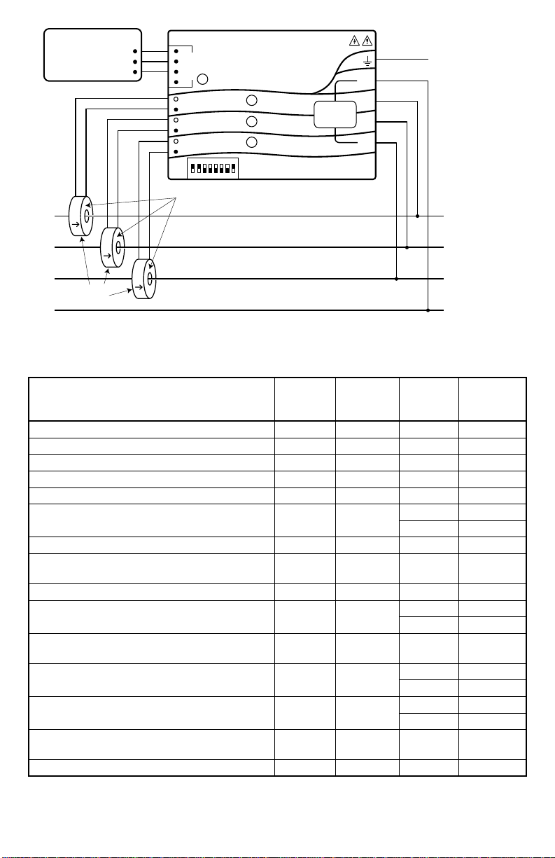
Figure 1: WattNode Wiring Diagram
2.2 Electrical Service Types
Electrical
Service (or Load) Types
Line-to-
Neutral
(Vac)
1 Phase 2 Wire 120V with neutral 96 – 138 n.a. 3Y-208 N and ØA
1 Phase 2 Wire 230V with neutral (non-N.A.) 184 – 264 n.a. 3Y-400 N and ØA
1 Phase 2 Wire 277V with neutral 222 – 318 n.a. 3Y-480 N and ØA
1 Phase 2 Wire 208V no neutral n.a. 166 – 276 3D-240 ØA and ØB
1 Phase 2 Wire 240V no neutral n.a. 166 – 276 3D-240 ØA and ØB
1 Phase 3 Wire 120V/240V with neutral 96 – 138 166 – 276
3 Phase 3 Wire Delta 208V no neutral n.a. 166 – 276 3D-240 ØA and ØB
3 Phase 3 Wire Delta 400V no neutral (nonN.A.)
3 Phase 3 Wire Delta 480V no neutral n.a. 384 – 552 3D-480 ØA and ØB
3 Phase 4 Wire Wye 120V/208V with neutral 96 – 138 166 – 276
3 Phase 4 Wire Delta 120/208/240V with
neutral
3 Phase 4 Wire Wye 230V/400V with neutral
(non-N.A.)
3 Phase 4 Wire Wye 277V/480V with neutral 222 – 318 384 – 552
3 Phase 4 Wire Delta 240/415/480V with
neutral
3 Phase 4 Wire Wye 347V/600V with neutral 278 – 399 480 – 690 3Y-600 N and ØA
n.a. 320 – 460 3D-400
96 – 138 166 – 276 3D-240 ØA and ØB
184 – 264 320 – 460
222 – 318 384 – 552 3D-480 ØA and ØB
Table 1: WattNode Models
Line-to-
Line
(Vac)
Meter
Service
Type
3Y-208 N and ØA
3D-240 ØA and ØB
3Y-208 N and ØA
3D-240 ØA and ØB
3Y-400 N and
3D-400 ØA and ØB
3Y-480 N and ØA
3D-480 ØA and ØB
Meter
Powered
by
ØA and ØB
ØA
4
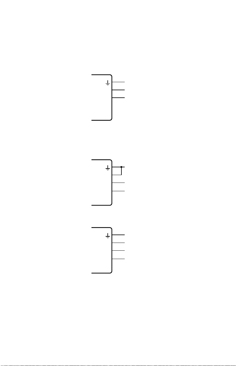
Table 1 above lists the WattNode models and common circuit types. In the “Electrical Service
Ground
Ground
Ground
Types” column, when two voltages are listed with a slash between them, they indicate the line-toneutral / line-to-line voltages. The “Line-to-Neutral” and “Line-to-Line” columns show the operating
ranges for the WattNode meters. “non-N.A.” refers to non-North American electrical services.
Connect the line voltages to the meter inputs as shown in the following figures for each service
type. See Figure 1 above for an overview.
2.2.1 Single-Phase Two-Wire with Neutral
This is a common residential and branch circuit connection. Up to three such circuits may be monitored with one meter by also using the ØB and ØC inputs.
W
ATT
N
N
ØA
ODE
ØB
®
ØC
2.2.2 Single-Phase Two-Wire No Neutral
This circuit occurs in residential (commonly 120/240 Vac) and some commercial applications.
The meter is powered from the ØA and ØB terminals. We recommend connecting the N terminal
to ground to provide a clean voltage reference for the measurement circuitry (no current will flow
through this terminal).
Neutral
Line
W
ATT
N
N
ODE
ØA
ØB
®
ØC
L1
L2
2.2.3 Single-Phase Three-Wire with Neutral
This is a common residential service at 120/240 Vac.
W
ATT
N
N
ØA
ODE
ØB
®
ØC
2.2.4 Three-Phase Three-Wire Delta No Neutral
This is common in commercial and industrial settings. In some cases, the service may be fourwire, wye but the load may only be three wire (no neutral).
Occasionally, a load will only be connected to two of the three lines (say L1 and L2). For this case,
connect the two active lines to the ØA and ØB terminals and connect two CTs for the two lines.
Neutral
L1
L2
5
 Loading...