

Page 1
User’s Guide for LNAD (FCC ID: LHJ-LNAD)
Rev: 0.7
Page 1 of 8
User’s Guide and Test Manual for LTE Modem
(Type Approval Model: LNAD)
1. Product Overview
LNAD wireless modem is a proprietary modem designed and manufactured by Continental Automotive
Systems, Inc. The modem will be integrated into Data Connectivity Modules (DCMs) designed and produced
by Continental for use by automotive OEMs. DCMs will be installed into vehicles during the OEM’s factory
assembly process and will not be accessible without use of special tools. Primary use-cases are data-centric
with data and voice connections to Telematics Service Providers (TSP).
High-level List of features
• Supported Protocols and Bands
o LTE band 4 (DL: 2110-2155 MHz, UL 1710-1755 MHz).
o LTE band 17 (DL: 734-746 MHz, UL: 704-716 MHz)
o LTE band 2 (1900 MHz)
o LTE band 5 (850 MHz)
o 5MHz and 10 MHz bandwidths supported for all LTE bands
o UMTS bands: II and V
o GSM operation not supported
• Binary SMS
• AGPS – not supported
• 911 and personal calls will not be placed (blocked by DCM, the telematics host)
• Solderable surface mount design for integration into DCM design
• WiFi circuit is populated but not powered or used.
The LNAD module is a proprietary product designed and manufactured by Continental Automotive Systems, Inc.
The module will be integrated into telecommunication control devices produced by Continental for its automotive
customers. Because LNAD is not intended for sale as a stand-alone device or offered for sale to general public, the
user’s manual and sales brochure are not applicable to this product.
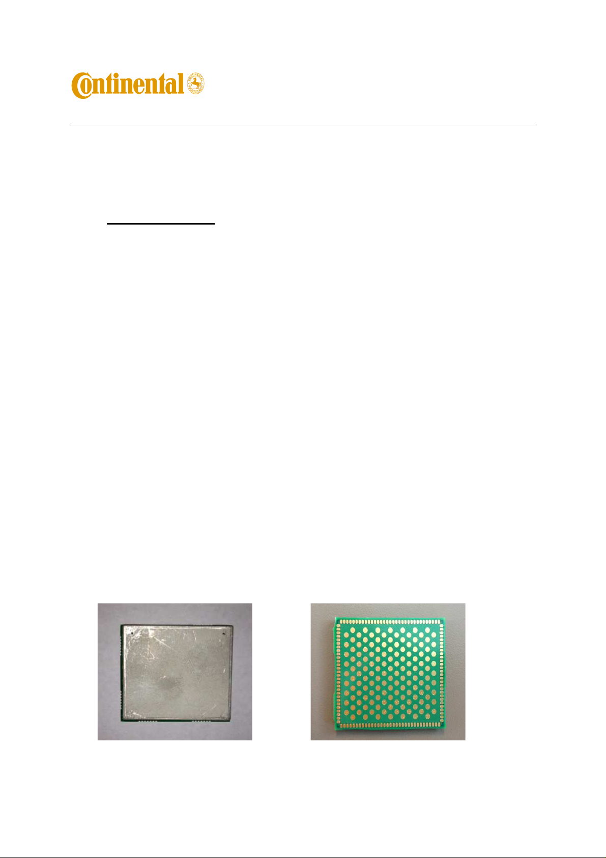
LNAD is a surface mount (SMT) module with 122 solderable connection pads. The module is LGA package type
with dimensions 35x40x3.5mm. Two-piece shield provides RF protection.
Fig .1. Top view of LNAD. Fig. 2. Bottom view of LNAD
Page 2
User’s Guide for LNAD (FCC ID: LHJ-LNAD)
Rev: 0.7
Page 2 of 8
2. FCC Note
This device complies with Parts 22, 24, and 27 of the FCC Rules. The FCC ID for this device is LHJ-LNAD. The
device meets the mobile RF exposure limit at a 20 cm separation disctance as specified in §2.1091 of the FCC Rules
and Regulations and Health Canada Safety Code 6.
Operation is subject to the following conditions:
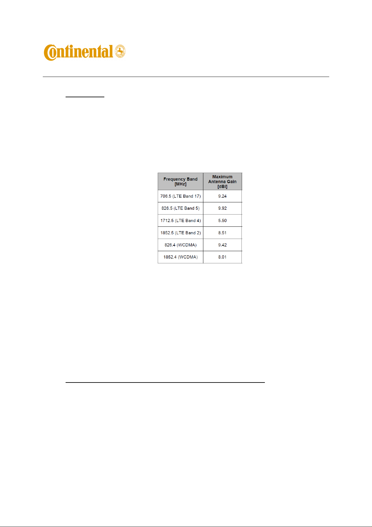
The device must be installed to provide a separation distance of at least 20cm from all persons and must not
be co-located or operating in conjunction with any other antenna or transmitter.
For mobile and fixed operation configurations the antenna gain, including cable loss, must not exceed the
limits listed in the table below:
Changes or modifications to this system by other than an authorized service facility could void authorization to use
this equipment.
If LNAD module is incorporated into mobile or fixed host devices, the host devices may use the FCC Grants of the
LNAD modules for the final product if they meet conditions listed above. The label of the host product shall be
clearly visible from the outside and include text “Contains FCC ID: LHJLNAD”. The integration is limited to host
devices where there is at least 20 cm separation between antenna and a person.
3. Testing Instructions for Regulatory Approval Purposes
3.1 Set-up requirements:
[1] 12V DC Power supply capable of sourcing 1A.
[2] LNAD on a development board, see Fig. 3.
[3] Baby Junior (Jr.) board connected to the development board. See Fig. 4 for complete assembly.
[4] A LTE capable call box (CMW500).
[5] Test SIM card.
[6] USB cable.
[7] RF cable for primary RF paths, secondary path termination is optional.
[8] Drivers.
Page 3
User’s Guide for LNAD (FCC ID: LHJ-LNAD)
Rev: 0.7
Page 3 of 8
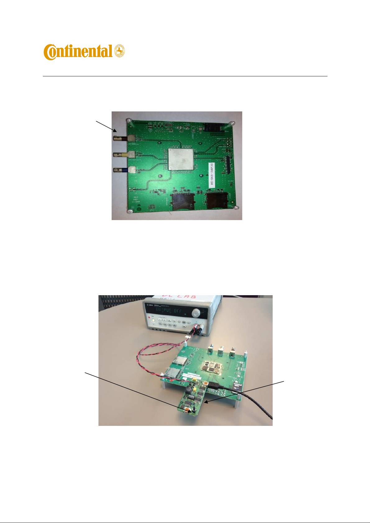
Primary RF port –
Brown connector
RF Ports on the development board:
- Brown – Primary RF port (MIMO1)
- Beige – Diversity RF Port (MIMO2)
- Blue – GPS (do not use)
ON/OFF
Button on Jr. Board
Figure 3. LNAD on a development board
SIM card is inserted into
holder on the bottom of the
Jr. board
Fig. 4 Complete test set-up for LNAD with Jr. Board connected.
Page 4

User’s Guide for LNAD (FCC ID: LHJ-LNAD)
Rev: 0.7
Page 4 of 8
3.2 Installing drivers first time
Note:
This is for install Qualcomm USB driver on Windows 7 only. It does not apply for Windows XP
(For Windows XP, just do step [3] only)
[1] Suspend BitLocker if the PC has one
From Control Panel -> BitLocker Drive Encryption (for driver C:)
[2] Set The TESTSIGNING boot configuration option
http://msdn.microsoft.com/en-us/library/windows/hardware/ff553484(v=vs.85).aspx
Open command line (Need to select “
Type following command and make sure it is successful:
Bcdedit.exe -set TESTSIGNING ON
[3] Reboot the PC
[4] Install Qualcomm USB Driver
“Qualcomm USB Drivers For Windows.msi”
[5] Resume BitLocker if applicable
[6] Reboot PC
[7] Connect LNAD Jr. Board via USB to the PC and let Windows to detect the device (it will take a while
for the first time).
[8]
Important:
the PC. Go to 5 (
There is a known issue affecting Windows 7 if the drivers were previously installed in
Appendix 1
) for resolution.
Run as administrator”
)
3.3 Power-up and Establish Communication:
[9] Load provided drivers onto the lab PC. Drivers are listed in Fig. 5.
Fig. 5 List of drivers.
[10] Attach the Jr. Board to the development board as shown in Fig. 4.
[11] Program the power supply to 12V and set the current limit to 1A. IMPORTANT: Make certain the
power supply output is off.
[12] Connect the Jr. Board to the power supply.
[13] Connect the Jr. Board to the PC using the USB cable.
[14] Turn on the power supply output. Current draw by the development board should be <1mA. Green
LEDs will turn ON: two on the development board and eight on the Jr. Board. .
Page 5

LED
User’s Guide for LNAD (FCC ID: LHJ-LNAD)
Rev: 0.7
Page 5 of 8
[15] Press and release ON/OFF button on the Jr. Board.
[16] NAD-ON Green LED on the development board will turn ON. Current draw will be fluctuating at
around 60mA (without RF connection).
NAD-ON
Fig. 6 NAD-ON LED Location and Band Selection Indicators.
[17] The PC will auto-install the drivers or request path for the drivers. Install the drivers if needed.
[18] Using Device Manager confirm that the following devices were successfully installed:
Android Composite ADB Interface
Qualcomm HS-USB Android Modem 9025
Qualcomm Wireless HW-USB Ethernet Adaptor 9025
Qualcomm HS-USB Diagnostics 9025 (COM ##)
Qualcomm HS-USB NMEA 9025(COMM ##)
[19] In Device Manager, Right Click on the Qualcomm HS-USB Android Modem 9025 and in “Modem”
Tab find which COM Port it’s assign to (COM 19 in my example).
Use this port for AT commands
Page 6

This is the SW version
User’s Guide for LNAD (FCC ID: LHJ-LNAD)
Rev: 0.7
Page 6 of 8
Fig. 7 COM Port allocation for the Modem used for AT communication.
[20] Open Hyper Terminal or another communication program. Select the COM Port corresponding to the
Android Modem noted in step [18]. Copy of Hyper Terminal.exe for Windows 7 is provided.
[21] AT command communication is now established. AT commands may not echo in HyperTerminal. To
enable echo type ATE.
Examples of AT commands and responses from LNAD:
AT
OK
AT+GSN
004401810005468 (example)
AT+GMR
+GMR:
"M9615ACETWMLZD4030",
"M9615ACETRMAZB12230_CAS-2.0.0",
"M9615ACETWTAZM5010153",
"NAD9x15_COMM_02.00R",
"M9615AAAARNLZA1502157_CAS-2.0.0",
"M9615ACETRMAZR1100159",
"M9615ACETRMAZL140125"
OK
[22] The band selection can be checked with the Band Selection Indicator LEDs, shown in Fig.6, as
follows:
Band ANT_SEL0 ANT_SEL1 ANT_SEL2
B2 OFF OFF OFF
B17 ON OFF ON
B4 OFF ON ON
B5 OFF ON ON
3.4 Making a Voice Call:
[1] With the LNAD connected as above, connect the RF cable to a call box.
[2] Wait for the NAD to register; this should be less than 30 seconds.
[3] For mobile originated call, type ATD[number] e.g. ATD123;
[4] For mobile terminated call, press the “originate call” soft-key.
VOICE CALLS ONLY:
The terminal will indicate the incoming call with “RING”.
Type ATA to answer the call.
To end the call, type AT+CHUP, or press the “end call” soft-key on the call box.
3.5 Dial Up Networking Configuration:
[1] Go to Start -> Settings -> Network and Dial Up connections -> Make New Connection;
Page 7

User’s Guide for LNAD (FCC ID: LHJ-LNAD)
Rev: 0.7
Page 7 of 8
[2] Follow the windows system Network Connection Wizard instructions, Choose Dial up to private
network option then click on Next;
[3] Select Qualcomm HS-USB Android Modem 9025
[4] Set the Phone number as *99#
[5] Press “Dial”
[6] Connection Status is Connected
[7] On the call box, set-up the FTP server
[8] In FileZila, enter the address for the FTP server on the call box
3.6 Powering off LNAD
[1] Terminate the call if the NAD is connected.
[2] Press and hold ON/OFF button on the Jr. board for about 3 second. Release the button.
[3] Current drain should drop to 9mA within 20 seconds indicating the LNAD is off. Turn off the output
of the 12V supply.
[4] The LNAD setup may now be disassembled.
4. Support of AT Commands
[1] LNAD supports AT commands per 3GPP27.005 and per AT&T specification with following
exceptions listed below.
[2] Not supported AT commands:
* $ARME and $ARMEE: related to RPM configuration
* +CTSA and +CBKLT: used for emulating touchscreen action and turning on/off the display backlight.
Probably not applicable for embedded module.
* +CESP: used for SMS block mode protocol
[3] AT Commands with limited support:
* +PACSP: appears to only work when camped on 3G network (e.g., UMTS)
* +++ packet data escape sequence may only be supported for UMTS circuit switched data.
5. Appendix 1: Windows 7 USB driver installation issue and solution
Device Manager displays many 'Unknown device' entries referencing mfe_firehkmp in the Network adapters
section
5.1
Environment
McAfee Host Intrusion Prevention 7.0
Microsoft Windows 7
5.2
Problem
Multiple Unknown device entries are listed in the Network Adapters section of the Device
Manager. Each of these entries reference mfe_firehkmp.
An affected system may also be unable to use a VPN Client or install any software that uses NDIS
5.x drivers because no additional NetLuids can be enumerated.
Page 8

User’s Guide for LNAD (FCC ID: LHJ-LNAD)
Rev: 0.7
Page 8 of 8
5.3
Cause
The Host Intrusion Prevention (Host IPS) 7.0 NDIS 5.x driver does not correctly remove and clean
up NetLuid on systems running Microsoft Windows 7. Over time, this causes all NetLuids to be
exhausted.
5.4
Solution
Use the following steps to fix this issue.
5.4.1 Open an Administrative command prompt.
5.4.2 Run the NDISCleanup utility for your specific system (x86 or x64) using the following
command:
ndiscleanup -cleanup -if 1
5.4.3 Run
psexec -i -d -s c:\windows\regedit.exe
regedit
the following way,
5.4.4 Navigate to the following key and delete it if it exists:
[HKEY_LOCAL_MACHINE\SYSTEM\CurrentControlSet\Enum\Root\MFE_FIREH
KMP]
5.4.5 Restart the system.
 Loading...