

Page 1

Continental Automotive
NCMF1_01
Abbreviation
Description
User Manual
of the Continental
Radio frequency transceiver
A
BBREVIATION REGISTER
CW
FCC
LF
Continuous Wave
Federal Communication Commission
Low Frequency
Model:
RF
TPMS Tire-Pressure Monitoring System
RKE Remote Keyless Entry System
PASE Passive Entry
Radio Frequency
1
Page 2

Continental Automotive
1 Purpose
This homologation report is written to describe the functions integrated into
the NewCMF1 System to prepare homologation for complete system to
answer LF regulation.
2 General Product Information
2.1 Applicant/Manufacturer
Continental Automotive GmbH
Siemensstrasse 12
93055 Regensburg, Germany
2.2 Brand
Continental
2.3 System Description
The Body Control Module (BCM) NewCMF1 is an integrated transmitter-
receiver (base station) in the vehicle that interfaces with the Remote Keyless Entry
(RKE) FOBIK using RF and LF. The BCM NewCMF1 contains the controlling logic for
the Passive Entry (pase) Keyless Go (PEKG) and Immobilizer (Immo).
The BCM New CMF1 communicates on the CAN vehicle communication bus.
The BCM New CMF1 also interfaces with the vehicle’s door handles, trunk/Liftgate
(as equipped) and multiple LF antennae for purposes of providing PEKG
functionality.
2
Page 3
Continental Automotive
Driver
Bumper
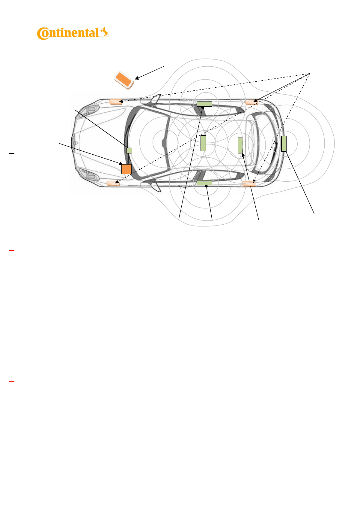
3 Systems Overview
BCM
New
CMF1
Fobik
LF Antenna
Passenger
LF Antenna
TPMS
LF Antenna
LF Antenna
Room’s 2/Trunk
3
Page 4

Continental Automotive
Fobik
4 Functions Variants
a. TPMS
(Tire-Pressure Monitoring System)
i. System Explanation
TPMS1
TPMS2
To control the pressure of vehicles wheels, the pressure captor (certificate done) transmit
information to the BCM in RF. The BCM decode the signal (with RF Receiver) and transmit
data on CSPI bus No LF transmission
TPMS3
b. RKE
BCM
TPMS4
(Remote Keyless Entry System)
i. System Explanation
To lock and unlock the vehicle at distance a function is implemented in the system. The
FOBIK transmit to the receiver an order. That it transmits on the CAN bus allows to achieve
function No LF transmission
RF
BCM
4
Page 5

Continental Automotive
Fobik
Immo
Transmission
Fobik
LF Antenna
LF Ant
LF Ant
LF Ant
LF Ant
c. PASE
(Passive Entry)
i. System Explanation
The system works by having a series of LF
(low frequency 125 kHz) transmitting
antennae both inside and outside the
vehicle. The external antennae are located in
the door handles. When the vehicle is
triggered, either by pulling the handle or
touching the handle, an LF signal is
transmitted from the antennas to the key.
The key becomes activated if it is sufficiently
close and it transmits its ID back to the
vehicle via RF to a receiver located in the
vehicle. If the key has the correct ID, the
PASE module unlocks the vehicle.
d. PASE
i. System Explanation
LF
RF
BCM
BCM
LF
When the battery of Fobik is totally discharged, the BCM contains a function
which pilots the antenna Room’s 1. This antenna allows communicating at short
distance with LF stage present on Fobik and to supply by field the Fobik to create a
Carrier Wave signal. The LF coil which is used to communicate and authenticate
Fobiks during Limp Home mode (125Khz).
5
Page 6

Continental Automotive
5 Radio Frequency Parameters
Following are the RF receiver parameters of the BCM NewCMF1:
US EU JP Units
Frequency 433,92 433,92 315 MHz
Receiver Model 40515519 40515519 40406556 -
Frequency tolerance untrimmed
Temperature range -40°C…+85°C
Data rate kbps
Receiver Bandwidth 300 kHz
Modulation -
Conducted sensitivity (typ./min.)
MER 10%
Operating Temperature -40 / +85 -40 / +85 -40 / +85 °C
Storage Temperature -40 / +85 -40 / +85 -40 / +85 °C
Nominal Supply Voltage 5 5 5 V
Run On supply current typ.
Single Conversion Mode
Run On supply current max.
Single Conversion Mode
-106 / -103 -106 / -103 -106 / -103 dBm
10,5 10,5 10,5 mA
14 14 14 mA
+/- 90 ppm
9,6 ±10%
FSK
6 LF parameters
Below are the technical parameters of the NewCMF1 LF transmitter:
Carrier frequency: 125 kHz
Frequency shift: +/- 0.3 %
Number of channels: 1
Modulation type: Amplitude Shift Keying (ASK)
Data rate: 3900 bit/s
Field strength: < 66 dBµA/m @ 10m
Supply voltage: 12V lead acid vehicle battery
DC/DC converter range: 9V to 40V
Voltage supply range: 9V up to 16V
Antenna type: Winded wire coil
Antenna Brand: all Continental, except Kazashi
Kazashi
Antenna Model: REF SI581 03 113 00,
285E4 JK60A, 285E5 JK60A,
28E6 5RA0A
Kazashi 350µH
Antenna gain: REF SI581 03 113 00: 0 dBi
285E4 JK60A: 0 dBi
285E5 JK60A: 0 dBi
28E6 5RA0A : 0 dBi
Kazashi 350µH: 0 dBi
6
Page 7

Continental Automotive
BCM NewCMF1
LF System
A2C12416900
A2C12417300
A2C11548900
7 Variants and Model designation
Reference Continental intern
Model:
NCMF1_01
configuration
L42 (EUR)
L42 (US)
L42 (Full V4)
8 LF system configurations for markets
8.1 USA/Canada
LF System configuration used for USA/Canada markets are (see above table
too):
L42
9 LF system antenna configuration
9.1 L42 System LF
7
Page 8

Continental Automotive
9.2 LF Antenna Type
LF System
References Comments Ferrite dimension Inductance Impedance Pictures 5
REF SI581 03 113 00 Door Handle 60x10x3 mm3 145µH±6% 113Ω±6%
285E4 JK60A or 285E5
JK60A
28E6 5RA0A Interior 100x13x4 mm3 145µH±6% 113Ω±6%
350µH/7 Ohms Kazashi 32x3mm 350µH±6% 7Ω±6%
Bumper/Interior 70x13x4 mm3 145µH±6% 113Ω±6% 1
L42
2
1
1
8
Page 9

Continental Automotive
Label USA/ Canada
Continental
NCMF1_01
FCC ID:KR5NCMF101
IC:7812D-NCMF101
Owner Manual Canada
IC:7812D-NCMF101
Operation is subject to the following two conditions:
(1) this device may not cause harmful interference, and (2) this device must accept any
interference received, including interference that may cause undesired operation.
Le présent appareil est conforme aux CNR d'Industrie Canada applicables aux
appareils radio exempts de licence. L'exploitation est autorisée aux deux conditions
suivantes :
(1) l'appareil ne doit pas produire de brouillage, et (2) l'utilisateur de l'appareil doit
accepter tout brouillage radioélectrique subi, même si le brouillage est susceptible
d'en compromettre le fonctionnement.
Owner Manual USA
FCC ID:KR5NCMF101
This device complies with Part 15 of the FCC Rules. Operation is subject
to the following two conditions:
(1) this device may not cause harmful interference, and (2) this device must
accept any interference received, including interference that may cause
undesired operation.
Changes or modifications not expressly approved by the party responsible
for compliance could void the user's authority to operate the equipment.
9
 Loading...