

Page 1

STANDARD PRACTICE
MAINTENANCE
MANUAL
SPARK IGNITED ENGINES
Technical Portions Accepted by the Federal Aviation Administration
Publication M-0, Revision 1 CHANGE 3
©
2023 CONTINENTAL AEROSPACE TECHNOLOGIES, INC. JAN 2023
Page 2
Supersedure Notice
This manual incorporates maintenance and service information contained in Continental Aerospace Technologies™
Service Documents common to the horizontally opposed, spark ignition, aviation gasoline (AvGas) engines
conforming to Type Certificate held by Continental Motors, Inc. This document is supplemental to the Instructions
for Continued Airworthiness provided in the manuals listed in Section 1-1.1. Instructions contained in the Service
Documents listed in Section 1-2.4 are superseded by instructions in this manual upon release, except for those
Mandatory Service Bulletins (MSBs) and Critical Service Bulletins (CSBs) linked to Airworthiness Directives.
Effective Changes for this Manual
0 ..... 15 September 2019
1 ...........1 February 2021
2 ............26 August 2021
3 ............ 6 January 2023
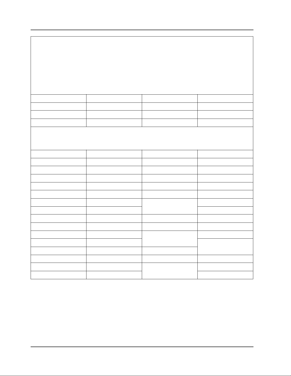
List of Effective Pages
Document Title: Standard Practice Maintenance Manual
Publication Number: M-0 Initial Publication Date: 15 September 2019
Page Change Page Change Page Change Page Change
Cover............................3 3-7 ................................0 6-6 thru 6-16 ................ 0 6-54..............................3
A...................................3 3-8 thru 3-12.................2 6-17.............................. 3 6-55..............................0
B thru C (added)........... 3 3-13 ..............................0 6-18.............................. 1 6-56.............................. 1
i thru xviii ......................2 3-14 ..............................2 6-19 thru 6-32 .............. 0 6-57 thru 6-63...............0
1-1 ................................ 0 3-15 thru 3-17...............0 6-33.............................. 1 6-64.............................. 3
1-2 ................................ 3 3-18 thru 3-19...............2 6-33.1 thru
1-4 thru 1-11................. 0 3-20 thru 3-22 ...............0 6-154............................ 3
6-33.2 (added) ............. 1
6-65 thru 6-153............. 0
1-12 thru 1-13............... 3 3-23 thru 3-24...............2 6-34 thru 6-48 .............. 0 6-155 thru 6-156........... 2
1-14 thru 1-16............... 0 4-1 thru 4-2 ...................0 6-49.............................. 1 6-157 thru 6-164........... 0
2-1 thru 2-7...................1 5-1 thru 5-6 ...................0 6-49.1 thru
2-8 thru 2-24................. 0 5-7 ................................1 6-165.1 thru
6-49-4 (added) ............. 1
3-1 ................................ 1 5-8 ................................0 6-50 thru 6-51 .............. 1
6-165............................ 3
6-165.8 (added)............ 3
3-2 thru 3-3...................0 6-1 thru 6-3 ...................0 6-52 thru 6-53 .............. 0 6-166 thru 6-180........... 0
3-4 thru 3-5...................3 6-4 ................................3 6-53.1 thru
3-6 ................................ 1 6-5 ................................1 7-3 thru 7-4...................3
Published and printed in the U.S.A. by Continental Motors, Inc. dba Continental Aerospace Technologies
Available exclusively from the publisher: P.O. Box 90, Mobile, AL 36601
Copyright © 2019, 2021, 2023 Continental Aerospace Technologies, Inc. All rights reserved. This material may not be reprinted, republished,
broadcast, or otherwise altered without the publisher's written permission. This manual is provided without express, statutory, or implied
warranties. The publisher will not be held liable for any damages caused by or alleged to be caused by use, misuse, abuse, or misinterpretation
of the contents. Content is subject to change without notice. Other products and companies mentioned herein may be trademarks of the
respective owners.
6-53.6 (added) ............. 1
7-1 thru 7-2...................0
™
A Standard Practice Maintenance Manual
CHANGE 3 6 January 2023
Page 3

Page Change Page Change Page Change Page Change
7-5 thru 7-30.................0 12-1 thru 12-8 .............. 0
8-1 thru 8-18.................0 A-1 thru A-6 ................. 0
8-19 thru 8-20...............1 B-1 thru B-9 ................. 0
8-20.1 thru
8-20.6 (added)..............1
8-21 thru 8-25...............0 B-12 ............................. 2
8-26 ..............................1 B-13 thru B-16 ............. 0
8-27 thru 8-28 (added) .1 C-1 thru C-18 ............... 0
9-1 thru 9-3...................0 C-19 ............................. 3
9-4 ................................3 C-20 thru C-24 ............. 0
9-5 ................................0 C-25............................. 2
9-6 ................................1 C-26............................. 0
9-7 ................................0
9-8 thru 9-10 (added) ...1
10-1 thru 10-8...............0
10-9 ..............................3
10-10 ............................0
10-11 ............................3
B-10 ............................. 2
B-11 ............................. 3
10-12 ............................2
10-13 ............................3
10-14 thru 10-51...........0
10-52 ............................3
10-53 thru 10-55...........0
10-55.1 thru
10-55.16 (added)..........3
10-56 thru 10-63...........0
10-64 thru 10-65...........3
10-66 thru 10-68...........0
10-69 ............................3
10-70 thru 10-85...........0
10-86 ............................2
10-87 thru 10-107.........0
10-108 ..........................1
10-109 thru
10-114 (added).............1
11-1 thru 11-8...............0
Standard Practice Maintenance Manual B
6 January 2023 CHANGE 3
Page 4

Intentionally Left Blank
C Standard Practice Maintenance Manual
CHANGE 3 6 January 2023
Page 5

Preface
This manual was developed in accordance with Title 14, Code of Federal Regulations (CFR) Part
33, §33.4 as the Instructions for Continued Airworthiness (ICA) for Standard Practices.
Continental Motors, Inc. provides ICAs based on the design, testing, and certification of engines
and parts. Continental Motors, Inc. is the holder of the Type Certificate (TC) or Parts Manufacture
Approval (PMA) issued by the Federal Aviation Administration (FAA). Instructions in
Continental manuals, which include maintenance, repair limits, and overhaul instructions, are
applicable only to Continental Aerospace Technologies™ (Continental®) engines and parts.
Except for authorized owner preventive maintenance (defined in Title 14, Code of Federal
Regulations (CFR) Part 43 §§43.3 and 43.13), Continental ICAs are written for exclusive use by
FAA (or equivalent authority) licensed mechanics or FAA (or equivalent authority) certified
repair station employees.
Information and instructions contained in this manual anticipate the user possesses and applies the
knowledge, training, and experience commensurate with the requirements to meet the prerequisite
FAA license and/or certification requirements. No other use is authorized. It is the responsibility
of the owner to verify the mechanic or facility operating, maintaining, or servicing the engine uses
the most current ICA, including manual change pages, service documents, and FAA
Airworthiness Directives (ADs), to perform those functions.
Aftermarket parts installed on a Continental engine constitutes a deviation from type-design
criteria. Continental has not participated in design, test, or certification of any aftermarket parts.
Continental does not provide product manufacturing specifications to aftermarket parts
manufacturers and accepts no liability for the suitability, durability, longevity, or safety of such
parts installed on Continental engines. Installation of aftermarket parts on a Continental engine
must be performed using ICAs prepared by the manufacturer and found acceptable by the FAA
for the subject installation. Continental ICAs must not be used for such parts.
WARNING
Ensure you have the latest revision of this manual, any
applicable change pages, FAA Airworthiness Directives and
Continental service documents prior to commencing engine
service, inspection, maintenance, or overhaul.
To facilitate the use of current data, Continental provides the latest information on the Continental
web site (http://www.continental.aero). This information (applicable to current versions) includes
an index of manuals, links to active service documents, FAA Airworthiness Directives, and other
information applicable to the ICAs. Additionally, Continental technical publications (the current
version in electronic or printed format) are available through our publications distributor, Aircraft
Technical Publishers (ATP) (www.atp.com). Refer to “Related Publications” in Section 1-2.5. for
additional information about service subscriptions and ATP contact information (see Table 1-2).
Standard Practice Maintenance Manual i
15 Sep 2019
Page 6

Intentionally Left Blank
ii Standard Practice Maintenance Manual
15 Sep 2019
Page 7

Table of Contents
TABLE OF CONTENTS
Chapter 1. Introduction
1-1. Scope and Purpose of This Manual.............................................................................................. 1-1
1-1.1. Instructions for Continued Airworthiness........................................................................... 1-1
1-1.2. Advisories ........................................................................................................................... 1-3
1-1.3. Effectivity Symbols ............................................................................................................ 1-3
1-1.4. Using this Manual............................................................................................................... 1-4
1-1.5. Compliance......................................................................................................................... 1-6
1-1.6. Order of Precedence ........................................................................................................... 1-7
1-2. Publications .................................................................................................................................. 1-7
1-2.1. Publication Access.............................................................................................................. 1-7
1-2.2. Publication Changes ........................................................................................................... 1-7
1-2.3. Update/Change Distribution ...............................................................................................1-8
1-2.4. Service Documents ........................................................................................................... 1-10
1-2.4.1. Service Documents Incorporated in this Manual.................................................... 1-11
1-2.4.2. Service Documents Released After Publication ..................................................... 1-13
1-2.5. Related Publications ......................................................................................................... 1-15
1-2.5.1. Suggestions and Corrections................................................................................... 1-15
1-3. Contact Information ................................................................................................................... 1-16
1-4. Service Parts............................................................................................................................... 1-16
1-4.1. Service Part Applicability and Availability....................................................................... 1-16
1-4.2. Part Supersedure ............................................................................................................... 1-16
Chapter 2. Tools
2-1. Special Tools ................................................................................................................................ 2-1
2-1.1. Vendor Contact Information ...............................................................................................2-7
2-2. Mechanic’s Tools ....................................................................................................................... 2-24
Chapter 3. Lubricants, Sealants, and
Adhesives
3-1. Engine Oil Specifications............................................................................................................. 3-1
3-1.1. Oil Brand Selection ............................................................................................................ 3-1
3-2. Oil Change Intervals .................................................................................................................... 3-3
3-3. Additives ...................................................................................................................................... 3-3
3-4. Sealant, Lubricant, and Adhesive Applications............................................................................ 3-4
3-4.1. General Sealant Application Instructions ..........................................................................3-11
3-4.1.1. Four Cylinder Engine Crankcase Threading........................................................... 3-12
3-4.1.2. Six Cylinder Engine Crankcase Threading............................................................. 3-14
3-4.2. Scavenge Pump Body Sealant and Threading.................................................................. 3-18
3-4.3. Oil Pump Assembly Sealant and Threading ..................................................................... 3-19
3-4.4. Starter Adapter Assembly Sealant and Threading ............................................................ 3-23
3-4.5. Starter Adapter Accessory Drive Cover Sealant and Threading....................................... 3-24
Standard Practice Maintenance Manual iii
26 Aug 2021 CHANGE 2
Page 8

Table of Contents
Chapter 4. Airworthiness Limitation Section
Chapter 5.Engine Removal & Installation
5-1. Engine Removal ........................................................................................................................... 5-1
5-1.1. Tools and Consumable Supplies ......................................................................................... 5-1
5-1.2. Engine Removal Procedure ................................................................................................5-1
5-2. Engine Installation........................................................................................................................ 5-2
5-2.1. Common Tools and Consumable Supplies .........................................................................5-2
5-2.2. Engine Receipt and Handling .............................................................................................5-3
5-2.3. Uncrating the Engine ..........................................................................................................5-3
5-2.4. Crating an Engine for Shipping .......................................................................................... 5-3
5-2.5. Acceptance Inspection ........................................................................................................ 5-3
5-2.6. Engine Transport................................................................................................................. 5-4
5-2.7. Engine Installation Procedures ...........................................................................................5-4
5-2.8. Engine Adjustments and Component Replacement by OEMs and STC Converters.......... 5-5
5-2.9. Engine Pre-oiling ................................................................................................................ 5-7
Chapter 6. Engine Inspection and Service
6-1. Engine Inspection Introduction ....................................................................................................6-1
6-2. Inspection and Maintenance Schedule ......................................................................................... 6-1
6-3. Time Between Overhaul............................................................................................................... 6-1
6-4. Scheduled Inspections .................................................................................................................. 6-5
6-4.1. One Time Post - Installation Inspections............................................................................6-6
6-4.2. 25-Hour Initial Operation Inspection..................................................................................6-6
6-4.3. 50-Hour Engine Inspection................................................................................................. 6-8
6-4.4. 100-Hour (Annual) Engine Inspection ............................................................................... 6-9
6-4.5. 500-Hour Engine Inspection............................................................................................. 6-11
6-4.6. Visual Inspection............................................................................................................... 6-12
6-4.7. Engine Operational Check ................................................................................................6-14
6-4.7.1. Fuel Injection System Specifications ......................................................................6-15
6-4.7.2. Maintenance Preflight Inspection............................................................................ 6-20
6-4.7.3. Oil Pump Operational Check .................................................................................. 6-22
6-4.7.4. Fuel System Operational Check.............................................................................. 6-23
6-4.7.5. Magneto RPM Drop Check..................................................................................... 6-31
6-4.7.6. Engine Shutdown .................................................................................................... 6-32
6-4.8. Engine Oil Servicing......................................................................................................... 6-33
6-4.8.1. Check and Replenish Engine Oil Level ..................................................................6-33
6-4.8.2. Oil Change and Filter/Screen Replacement ............................................................ 6-49
6-4.8.3. Check for Oil Leaks ................................................................................................ 6-52
6-4.8.4. Oil Sample Collection ............................................................................................. 6-52
6-4.8.5. Oil Trend Monitoring and Spectrographic Oil Analysis......................................... 6-53
6-4.9. Ignition System Maintenance ........................................................................................... 6-54
6-4.9.1. Ignition Timing ....................................................................................................... 6-54
6-4.9.2. Spark Plug Maintenance.......................................................................................... 6-62
6-4.9.3. Ignition Harness Maintenance.................................................................................6-66
6-4.10. Engine Adjustments........................................................................................................ 6-68
6-4.10.1. Oil Pressure Adjustment........................................................................................ 6-68
6-4.10.2. Fuel System Adjustment ....................................................................................... 6-70
6-4.10.3. Manifold Pressure Adjustment.............................................................................. 6-91
iv Standard Practice Maintenance Manual
CHANGE 2 26 Aug 2021
Page 9

Table of Contents
6-4.10.4. Belt Tension Check and Adjustment .................................................................... 6-96
6-4.11. Cylinder Inspections..................................................................................................... 6-102
6-4.11.1. Cylinder Visual Inspection.................................................................................. 6-103
6-4.11.2. Differential Pressure Test.................................................................................... 6-105
6-4.11.3. Cylinder Borescope Inspection ........................................................................... 6-113
6-4.11.4. Cylinder to Crankcase Mounting Deck Inspection............................................. 6-117
6-4.11.5. Baffle Inspection ................................................................................................. 6-118
6-4.11.6. Cowling Inspection ............................................................................................. 6-122
6-4.12. Crankcase Inspection.................................................................................................... 6-122
6-4.12.1. Crankcase Critical Stress Areas .......................................................................... 6-125
6-4.13. Engine Mount Inspection.............................................................................................. 6-129
6-4.14. Induction System Inspection ........................................................................................ 6-129
6-4.15. Ignition System Inspection ........................................................................................... 6-131
6-4.15.1. Impulse Coupling Functional Check................................................................... 6-133
6-4.15.2. Starting Vibrator Functional Check .................................................................... 6-134
6-4.15.3. Magneto Drive Coupling Inspection................................................................... 6-134
6-4.16. Engine Gauge Inspection.............................................................................................. 6-135
6-4.17. Fuel System Inspection................................................................................................. 6-136
6-4.18. Throttle and Mixture Control Lever Inspection............................................................ 6-137
6-4.19. Engine Control Linkage Inspection.............................................................................. 6-139
6-4.20. Induction System Drain Inspection .............................................................................. 6-141
6-4.20.1. Induction System Drain Inspection (Naturally Aspirated Engines).................... 6-142
6-4.20.2. Induction System Drain Inspection (Turbocharged Engines)............................. 6-143
6-4.21. Turbocharger and Exhaust System Inspection.............................................................. 6-144
6-4.21.1. Turbocharger Oil Supply Check Valve Inspection ............................................. 6-149
6-4.22. Alternator Inspection .................................................................................................... 6-153
6-4.22.1. Alternator Drive Coupling Inspection ................................................................ 6-154
6-4.22.2. Alternator Drive Coupling Inspection ................................................................ 6-155
6-5. Unscheduled Maintenance ....................................................................................................... 6-158
6-5.1. Propeller Strike ............................................................................................................... 6-158
6-5.1.1. Propeller Strike Inspection.................................................................................... 6-158
6-5.2. Hydraulic Lock Inspection ............................................................................................. 6-159
6-5.3. Engine Overspeed Inspections........................................................................................ 6-160
6-5.3.1. Category I Overspeed Inspection.......................................................................... 6-161
6-5.3.2. Category II Overspeed Inspection......................................................................... 6-161
6-5.3.3. Category III Overspeed Inspection ....................................................................... 6-162
6-5.4. Turbocharger Overboost................................................................................................. 6-162
6-5.5. Lightning Strike Inspection ............................................................................................ 6-162
6-5.6. Contaminated Fuel System Inspection ........................................................................... 6-163
6-5.7. Foreign Object Contamination Inspection...................................................................... 6-163
6-5.8. Sticking or Stuck Valves................................................................................................. 6-164
6-6. Inspection Checklists ............................................................................................................... 6-166
Chapter 7. Engine Operation
7-1. Introduction .................................................................................................................................. 7-1
7-2. Flight Prerequisites....................................................................................................................... 7-1
7-2.1. Oil Change Interval ............................................................................................................ 7-1
7-2.2. Engine Fuel Requirements.................................................................................................. 7-2
7-2.3. Engine Operation after Cylinder Replacement and/or Major Overhaul............................. 7-6
7-2.4. Flight Check and Break-In ................................................................................................. 7-8
Standard Practice Maintenance Manual v
26 Aug 2021 CHANGE 2
Page 10

Table of Contents
7-2.4.1. Engine Break-In ........................................................................................................7-8
7-2.4.2. Flight Check .............................................................................................................. 7-9
7-3. Normal Operation.......................................................................................................................7-18
7-3.1. Pre-operational Requirements........................................................................................... 7-18
7-3.2. Engine Start....................................................................................................................... 7-19
7-3.2.1. Cold Start................................................................................................................. 7-20
7-3.2.2. Flooded Engine ....................................................................................................... 7-20
7-3.2.3. Hot Start .................................................................................................................. 7-21
7-3.3. Ground Run-up .................................................................................................................7-22
7-3.4. Engine Shutdown.............................................................................................................. 7-24
7-4. Engine Operation in Abnormal Environments ........................................................................... 7-25
7-4.1. Engine Operation in Extreme Cold................................................................................... 7-25
7-4.1.1. Engine Preheating ................................................................................................... 7-26
Chapter 8. Troubleshooting
8-1. General Troubleshooting.............................................................................................................. 8-2
8-1.1. General Troubleshooting for Engines equipped with a Carburetor.................................... 8-2
8-1.2. General Troubleshooting for Engines with Continental Continuous Flow Fuel Injection
Systems .........................................................................................................................................8-3
8-1.3. Engine Runs Rough ............................................................................................................ 8-4
8-1.3.1. Engine Runs Rough (equipped with Carburetor)...................................................... 8-4
8-1.3.2. Engine Runs Rough (equipped with Continental Continuous Flow Fuel Injection Sys-
tem).........................................................................................................................................8-5
8-1.4. Engine Will Not Run........................................................................................................... 8-6
8-1.5. Engine Indication Malfunctions.......................................................................................... 8-7
8-1.6. Engine Performance Malfunctions ..................................................................................... 8-8
8-2. Induction System.......................................................................................................................... 8-9
8-2.1. Engine Will Not Start.......................................................................................................... 8-9
8-2.2. Engine Will Not Run......................................................................................................... 8-10
8-2.3. Engine Lacks Power/Manifold Pressure Low (Naturally Aspirated Models) .................. 8-10
8-2.4. Engine Lacks Power/Manifold Pressure Low (Turbocharged Models)............................ 8-11
8-3. Continental Continuous Flow Fuel Injection System.................................................................8-12
8-3.1. Engine Will Not Start........................................................................................................ 8-12
8-3.2. Fluctuating or Erroneous Fuel Flow ................................................................................. 8-13
8-3.3. Poor Acceleration.............................................................................................................. 8-13
8-3.4. Fuel Injector Operational Check....................................................................................... 8-14
8-4. Charging System ........................................................................................................................8-16
8-5. Starting System...........................................................................................................................8-16
8-6. Ignition System........................................................................................................................... 8-17
8-6.1. Ignition Harness and Spark Plug Diagnostics................................................................... 8-18
8-7. Lubrication System.....................................................................................................................8-19
8-8. Engine Cylinders ........................................................................................................................ 8-21
8-9. Crankcase ................................................................................................................................... 8-23
8-9.1. Excess Crankcase Pressure ............................................................................................... 8-24
8-10. Turbocharger and Exhaust System ...........................................................................................8-25
8-10.1. Freeing Turbine Shafts Dragging or Frozen by Corrosion ............................................. 8-26
8-10.2. Oil Leaking from Turbocharger...................................................................................... 8-27
vi Standard Practice Maintenance Manual
CHANGE 2 26 Aug 2021
Page 11

Table of Contents
Chapter 9. Engine Preservation and Storage
9-1. Preserving and Storing an Engine................................................................................................ 9-1
9-1.1. Engine Preservation Checklist............................................................................................9-1
9-1.2. New or Unused Engine Storage.......................................................................................... 9-1
9-1.3. Installed Engine, Temporary Storage ................................................................................. 9-1
9-1.4. Installed Engine, Indefinite Storage ................................................................................... 9-3
9-1.5. Crated Engine, Indefinite Storage ...................................................................................... 9-4
9-1.6. Return an Engine to Service after Storage.......................................................................... 9-6
9-2. Turbocharger Preservation and Storage ....................................................................................... 9-8
9-2.1. Short Term Storage (on shelf)............................................................................................. 9-8
9-2.2. Short Term Storage (on aircraft) .........................................................................................9-8
9-2.3. Long Term Storage (on shelf) .............................................................................................9-8
9-2.4. Long Term Storage (on aircraft) ......................................................................................... 9-8
9-2.5. Shelf Life ............................................................................................................................ 9-8
9-2.6. Turbocharger Pre-Lubrication (not installed) ..................................................................... 9-9
9-2.7. Turbocharger Pre-Lubrication (on aircraft) ........................................................................ 9-9
Chapter 10.Non-Overhaul Repair and
Replacement
10-1. Parts Replacement.................................................................................................................... 10-1
10-2. Fuel Injector Replacement ....................................................................................................... 10-3
10-2.1. Nozzle Identification ...................................................................................................... 10-3
10-2.2. Fuel Injector Removal (Turbocharged Engines) ............................................................ 10-4
10-2.3. Fuel Injector Installation (Turbocharged Engines)......................................................... 10-4
10-2.4. Fuel Injector Removal (Naturally Aspirated Engines) ................................................... 10-6
10-2.5. Fuel Injector Installation (Naturally Aspirated Engines)................................................ 10-6
10-3. Induction Drain Connector Replacement................................................................................. 10-8
10-3.1. Induction Drain Connector Removal and Cleaning ....................................................... 10-8
10-3.2. Induction Drain Connector Installation .......................................................................... 10-8
10-4. Alternator Replacement............................................................................................................ 10-9
10-4.1. Gear Driven Alternator Replacement, Forward Mount ................................................ 10-9
10-4.1.1. Gear Driven Alternator Removal ......................................................................... 10-9
10-4.1.2. Alternator Drive Coupling Removal .................................................................. 10-11
10-4.1.3. Alternator Drive Coupling Installation .............................................................. 10-11
10-4.1.4. Alternator Drive Coupling Slippage Inspection ................................................. 10-12
10-4.1.5. Gear Driven Alternator Installation ................................................................... 10-13
10-4.2. Gear Driven Alternator Replacement, Aft Mount ....................................................... 10-14
10-4.2.1. Gear Driven Alternator Removal ....................................................................... 10-14
10-4.2.2. Alternator Drive Hub Removal .......................................................................... 10-16
10-4.2.3. Alternator Drive Hub Installation ...................................................................... 10-16
10-4.2.4. Gear Driven Alternator Installation ................................................................... 10-18
10-4.3. Alternator Service Instructions ..................................................................................... 10-19
10-5. Magneto Replacement............................................................................................................ 10-21
10-5.1. Continental Magneto Removal..................................................................................... 10-21
10-5.2. Continental Magneto Installation ................................................................................. 10-22
10-5.3. Champion (Slick) Magneto Removal ........................................................................... 10-24
10-5.4. Champion (Slick) Magneto Installation ....................................................................... 10-25
10-5.5. Magneto Filter Replacement ........................................................................................ 10-27
10-5.5.1. Continental Magneto Filter Replacement ........................................................... 10-27
Standard Practice Maintenance Manual vii
26 Aug 2021 CHANGE 2
Page 12

Table of Contents
10-5.5.2. Champion (Slick) Magneto Filter Replacement..................................................10-29
10-6. Cylinder Repairs..................................................................................................................... 10-31
10-6.1. Cylinder Replacement................................................................................................... 10-32
10-6.1.1. Cylinder Removal ............................................................................................... 10-32
10-6.1.2. Cylinder Installation............................................................................................ 10-34
10-6.1.3. Cylinder Torque .................................................................................................. 10-37
10-6.2. Cylinder Position Numbers........................................................................................... 10-38
10-6.3. Cylinder Head Repair ................................................................................................... 10-38
10-6.4. Cylinder Fin Tip Repair................................................................................................ 10-39
10-6.5. Cylinder Bore Inspection ..............................................................................................10-39
10-6.6. Cylinder Barrel Repair.................................................................................................. 10-39
10-6.7. Cylinder Bore Honing................................................................................................... 10-40
10-6.8. Cylinder Stud Replacement .......................................................................................... 10-41
10-6.9. Spark Plug Heli-coil Replacement................................................................................ 10-42
10-6.10. Cylinder Protective Coatings ...................................................................................... 10-43
10-6.11. Cylinder Bore and Piston Fit Specifications............................................................... 10-44
10-6.12. Legacy Product Replacement Valves.......................................................................... 10-53
10-7. Crankcase Repair.................................................................................................................... 10-56
10-8. Piston Replacement ................................................................................................................ 10-56
10-9. Crankshaft Repair................................................................................................................... 10-57
10-9.1. Crankshaft Counterweight Inspection and Repair ........................................................ 10-57
10-9.1.1. Crankshaft Counterweight Removal ................................................................... 10-76
10-9.1.2. Counterweight Identification............................................................................... 10-77
10-9.1.3. Crankshaft Counterweight Inspection................................................................. 10-82
10-9.1.4. Crankshaft Counterweight Bushing Bore Inspection.......................................... 10-83
10-9.1.5. Crankshaft Counterweight Bushing Replacement .............................................. 10-85
10-9.1.6. Crankshaft Hanger Blade Bushing Inspection ....................................................10-88
10-9.2. Oil Control Plug Replacement...................................................................................... 10-90
10-9.3. Crankshaft Plating Overhaul......................................................................................... 10-92
10-9.4. Connecting Rod Replacement ......................................................................................10-93
10-9.4.1. Connecting Rod Dimensional Inspection............................................................ 10-93
10-9.4.2. Connecting Rod Piston Pin Bushing Replacement ............................................. 10-98
10-9.4.3. Connecting Rod Piston Pin Bushing Boring..................................................... 10-100
10-10. Crankshaft Nose Oil Seal Replacement .............................................................................10-101
10-10.1. Solid Nose Oil Seal Removal ................................................................................... 10-101
10-10.2. Solid Nose Oil Seal Installation................................................................................ 10-102
10-10.3. Split Nose Oil Seal Removal .................................................................................... 10-104
10-10.4. Split Type Nose Oil Seal Installation ........................................................................ 10-104
10-11. Exhaust Flange to Cylinder Installation ............................................................................. 10-106
10-12. Lubrication System Maintenance....................................................................................... 10-108
10-12.1. Oil Filters Adapters................................................................................................... 10-108
10-12.2. Oil Filter Adapter Stud Replacement........................................................................ 10-110
10-12.3. Lubrication System Priming ..................................................................................... 10-112
10-12.3.1. Alternate Priming Method 1(470, 520, 550 engines only).............................. 10-112
10-12.3.2. Alternate Priming Method 2............................................................................ 10-112
10-13. Crankcase Breather System Maintenance .......................................................................... 10-114
Chapter 11. Non-Destructive Inspection
11-1. Visual Inspection ...................................................................................................................... 11-1
11-1.1. Gear Tooth Inspection..................................................................................................... 11-2
11-2. Fluorescent Penetrant Inspection.............................................................................................. 11-3
viii Standard Practice Maintenance Manual
CHANGE 2 26 Aug 2021
Page 13

Table of Contents
11-3. Magnetic Particle Inspection.....................................................................................................11-4
11-3.1. Connecting Rod Magnetic Particle Inspection ................................................................11-6
11-4. Ultrasonic Inspection.................................................................................................................11-7
11-4.1. Ultrasonic Inspection Certification..................................................................................11-7
11-4.2. Crankshaft Ultrasonic Inspection ....................................................................................11-8
Chapter 12. Engine Cleaning
12-1. Engine and Component Cleaning............................................................................................. 12-1
12-1.1. Cylinder Cleaning........................................................................................................... 12-6
12-1.2. Piston Cleaning............................................................................................................... 12-7
12-1.3. Cleaning Exhaust Parts................................................................................................... 12-8
12-1.4. Cleaning Aluminum Alloy Parts..................................................................................... 12-8
12-2. Dry Blasting ............................................................................................................................. 12-9
12-3. Vapor Blasting .......................................................................................................................... 12-9
12-4. Protective Coatings ................................................................................................................ 12-10
12-4.1. Alodine.......................................................................................................................... 12-10
12-4.2. Aviation Oil................................................................................................................... 12-10
12-4.3. Paint ...............................................................................................................................12-11
Appendix A.Glossary
A-1. Abbreviations/Acronyms.............................................................................................................A-1
A-2. Terms and Definitions .................................................................................................................A-3
Appendix B.Torque Specifications
B-1. General Information ....................................................................................................................B-1
B-1.1. Torque Tips ........................................................................................................................B-2
B-2. Part Supersedure..........................................................................................................................B-3
B-3. Torque Wrench and Extension Calculations................................................................................B-4
Appendix C.Maintenance Standards
C-1. Handling Parts .............................................................................................................................C-1
C-2. Replacement Parts .......................................................................................................................C-3
C-2.1. Background ........................................................................................................................C-3
C-2.2. Acceptable Replacement Parts...........................................................................................C-3
C-2.2.1. Know Your Supplier ................................................................................................C-3
C-2.3. 100% Parts Replacement Requirements ............................................................................C-4
C-2.4. Mandatory Overhaul Replacement Parts ...........................................................................C-5
C-2.5. Authorized Oversize/Undersize Parts ................................................................................C-8
C-2.6. Special Instructions............................................................................................................C-8
C-2.7. Engine Data Plate Replacement.........................................................................................C-8
C-2.7.1. Removal and Installation of Engine Data Plate........................................................C-8
C-3. Safety Wiring Hardware............................................................................................................C-10
C-4. Tab Washer Installation .............................................................................................................C-12
C-5. Heli-Coil® Insert Replacement.................................................................................................C-13
C-5.1. Heli-Coil Removal ...........................................................................................................C-14
C-5.2. Heli-Coil Insertion ...........................................................................................................C-15
C-6. Stud Replacement......................................................................................................................C-16
Standard Practice Maintenance Manual ix
26 Aug 2021 CHANGE 2
Page 14

Table of Contents
C-6.1. Stud Removal .................................................................................................................. C-16
C-6.1.1. Size-on-Size Rosan® Stud Removal..................................................................... C-16
C-6.1.2. Step-Type Rosan® Stud Removal......................................................................... C-17
C-6.2. Stud Installation .............................................................................................................. C-18
C-6.2.1. Rosan® Stud Installation....................................................................................... C-19
C-7. Cotter Pin Installation ............................................................................................................... C-20
C-8. Fuel System Service ................................................................................................................. C-21
C-8.1. Fuel System Purge........................................................................................................... C-21
C-9. Gasket Maker® Application..................................................................................................... C-22
C-10. Gasket Installation .................................................................................................................. C-23
C-10.1. Crush Washer Installation ............................................................................................. C-23
C-11. Hose and Tubing Installation .................................................................................................. C-24
C-12. Harness Routing...................................................................................................................... C-25
C-13. Plug and Fitting Removal ....................................................................................................... C-25
LIST OF TABLES
Table 1-1. Service Documents Incorporated in Manual .............................................. 1-11
Table 1-2. Related Publications ...................................................................................1-15
Table 2-1. Special Tools List .........................................................................................2-1
Table 2-2. Tools, Accessories, and Supply Vendors ..................................................... 2-7
Table 2-3. Common Tools ...........................................................................................2-24
Table 3-1. Qualified SAE J1899 Ashless Dispersant Engine Oil .................................. 3-2
Table 3-2. Qualified SAE J1966 Non-Dispersant Mineral Oil ......................................3-2
Table 3-3. Break-in Oil ..................................................................................................3-2
Table 3-4. Preservative Oil ............................................................................................3-2
Table 3-5. Sealants .........................................................................................................3-4
Table 3-6. Lubricants .....................................................................................................3-5
Table 3-7. Adhesives .....................................................................................................3-8
Table 3-8. Miscellaneous ...............................................................................................3-9
Table 5-1. Authorized Adjustments and Replacements ................................................5-6
Table 6-1. Engine Time Between Overhaul (TBO) .......................................................6-3
Table 6-2. Engine Inspection and Maintenance Schedule .............................................6-5
Table 6-3. Engine Operation Prerequisites ..................................................................6-14
Table 6-4. Fuel System Adjustment Values ................................................................6-15
Table 6-5. Static Ground Setup Compensation Table ................................................. 6-19
Table 6-6. IO-240-A, B With Standard Fuel Pump .....................................................6-20
Table 6-7. Magneto Timing Specifications - Geared Engines ....................................6-54
Table 6-8. Magneto Timing Specifications - Direct Drive Engines ............................ 6-54
Table 6-9. Spark Plug Application Chart ....................................................................6-63
Table 6-10. Spark Plug Rotation Chart .......................................................................... 6-65
Table 6-11. IO-360-D/DB Engine Altitude Leaning Schedule .....................................6-84
Table 6-12. IO-360-ES Engine Altitude Leaning Schedule ..........................................6-85
Table 6-13. IO-360-ES (Cirrus SR20) Engine Altitude Leaning Schedule ................... 6-86
Table 6-14. IO-550-A Engine Altitude Leaning Schedule ............................................6-87
Table 6-15. IO-550-B Engine Altitude Leaning Schedule ............................................ 6-88
Table 6-16. IO-550-C Engine Altitude Leaning Schedule ............................................ 6-89
Table 6-17. IO-550-D, E, F, & L Engine Altitude Leaning Schedule ...........................6-90
Table 6-18. VAPC Parameters ...................................................................................... 6-95
x Standard Practice Maintenance Manual
CHANGE 2 26 Aug 2021
Page 15

Table of Contents
Table 6-19. Cylinder Inspection Tasks and References ...............................................6-102
Table 6-20. Additional Cylinder Service Document References .................................6-102
Table 6-21. Differential Pressure Test Results ............................................................6-111
Table 6-22. Borescope Inspection Objectives and Corrective Actions .......................6-114
Table 6-23. Crankcase Casting Numbers .....................................................................6-122
Table 6-24. Exhaust Inspection Criteria ......................................................................6-144
Table 6-25. Overspeed Categories ...............................................................................6-160
Table 6-26. Engine Operational Checklist ...................................................................6-167
Table 6-27. 25-Hour Initial Operation Inspection Checklist .......................................6-169
Table 6-28. 50-Hour Engine Inspection Checklist ......................................................6-171
Table 6-29. 100-Hour Engine Inspection Checklist ....................................................6-173
Table 6-30. 500-Hour Engine Inspection Checklist ....................................................6-175
Table 6-31. Cylinder Inspection Checklist ..................................................................6-177
Table 7-1. Aviation Fuel Specifications ........................................................................7-3
Table 7-2. Authorized Fuels by Engine Model ..............................................................7-3
Table 7-3. IO-360-D/DB Engine Altitude Leaning Schedule .....................................7-11
Table 7-4. IO-360-ES Engine Altitude Leaning Schedule ..........................................7-12
Table 7-5. IO-360-ES (Cirrus SR20) Engine Altitude Leaning Schedule ...................7-13
Table 7-6. IO-550-A Engine Altitude Leaning Schedule ............................................7-14
Table 7-7. IO-550-B Engine Altitude Leaning Schedule ............................................7-15
Table 7-8. IO-550-C Engine Altitude Leaning Schedule ............................................7-16
Table 7-9. IO-550-D, E, F, & L Engine Altitude Leaning Schedule ...........................7-17
Table 9-1. Engine Preservation Checklist ......................................................................9-7
Table 10-1. Non-Overhaul Parts Replacement Reference .............................................10-1
Table 10-2. Parts Repair Reference ...............................................................................10-2
Table 10-3. Parts Handling Guidelines ..........................................................................10-2
Table 10-4. Alternator Drive Coupling Slippage .........................................................10-12
Table 10-5. Alternator Cross Reference ......................................................................10-20
Table 10-6. Cylinder Repair vs. Replacement Guidelines ...........................................10-31
Table 10-7. Cylinder Bore Surface Finish Specifications ...........................................10-41
Table 10-8. 5.250 Inch Cylinder Barrel Dimensions ...................................................10-45
Table 10-9. 5.250 Inch Cylinder Barrel Dimensions ...................................................10-46
Table 10-10. 5.250 Inch Piston to Cylinder Clearance ..................................................10-46
Table 10-11. 5.250 Inch Piston to Cylinder Clearance ..................................................10-46
Table 10-12. 5.250 Inch Piston to Cylinder Clearance ..................................................10-46
Table 10-13. 5.000 Inch Cylinder Barrel Dimensions ...................................................10-47
Table 10-14. 5.000 Inch Piston to Cylinder Clearance ..................................................10-47
Table 10-15. 5.000 Inch Piston to Cylinder Clearance ..................................................10-47
Table 10-16. 4.438 Inch Cylinder Barrel Dimensions ...................................................10-48
Table 10-17. 4.438 Inch Piston to Cylinder Clearance ..................................................10-48
Table 10-18. 4.062 Inch Cylinder Barrel Dimensions ...................................................10-49
Table 10-19. 4.062 Inch Piston to Cylinder Clearance ..................................................10-49
Table 10-20. Ring Gap Specifications ...........................................................................10-50
Table 10-21. Ring Gap Specifications ...........................................................................10-51
Table 10-22. Ring Gap Specifications ...........................................................................10-51
Table 10-23. Ring Gap Specifications ...........................................................................10-51
Standard Practice Maintenance Manual xi
26 Aug 2021 CHANGE 2
Page 16

Table of Contents
Table 10-24. Ring Gap Specifications ...........................................................................10-51
Table 10-25. Engine to Piston Cross Reference ............................................................10-52
Table 10-26. Engines Serial Number Applicability ......................................................10-53
Table 10-27. Replacement Components for Low Compression Ratio Cylinders .........10-54
Table 10-28. Cylinder Part Number Conversion ........................................................... 10-54
Table 10-29. Engine Power Train .................................................................................. 10-58
Table 10-30. Crankshaft Assembly Part Number History .............................................10-65
Table 10-31. Crankshaft Assemblies ............................................................................. 10-70
Table 10-32. Crankshaft Hanger Blade Bushing Sizes .................................................10-73
Table 10-33. Wide Rod Crankshaft ...............................................................................10-74
Table 10-34. Counterweight Supersedure .....................................................................10-76
Table 10-35. Counterweight Bushing Bore Dimensions ............................................... 10-84
Table 10-36. Counterweight Bushing Bore Dimensions ............................................... 10-87
Table 10-37. Counterweight Hanger Blade Bushing Dimensions .................................10-89
Table 10-38. Crankshaft Oil Plug Installation Specifications .......................................10-90
Table 10-39. Connecting Rod Specifications ................................................................10-96
Table 10-40. Exhaust Gaskets, Nuts, and Nut Torque Values .................................... 10-107
Table 11-1. Parts Requiring Fluorescent Penetrant Inspection .....................................11-3
Table 11-2. Magnetic Particle Inspection Reference .....................................................11-5
Table 11-3. Connecting Rod Magnetic Particle Inspection Criteria .............................. 11-6
Table 11-4. Crankshaft Ultrasonic Inspection Pass/Fail Action ....................................11-8
Table 12-1. Aircraft Engine Parts Cleaning Guidelines ................................................ 12-2
Table 12-2. Cleaning Tips ............................................................................................. 12-5
Table 12-3. Painting External Parts .............................................................................12-11
Table B-1. Appendix B, Quick Table Reference .......................................................... B-1
Table B-2. Component Specific Torque Specifications ................................................ B-6
Table B-3. Specific Torque Specifications (Non-Lubricated Hardware) .................... B-13
Table B-4. FADEC Components (Non-Lubricated Hardware) ................................... B-13
Table B-5. General Torque Specifications .................................................................. B-14
Table B-6. Hydraulic Line Torque Specifications ...................................................... B-14
Table B-7. Straight Thread Fitting Torque Specifications .......................................... B-15
Table B-8. Hose Fitting (“B” Nut) Torque Specifications .......................................... B-15
Table C-1. Mandatory Overhaul Replacement Parts ..................................................... C-5
Table C-2. Rosan® Stud Primary & Secondary Bore Specifications ......................... C-17
Table C-3. High Strength Sealant and Adhesive Part Numbers .................................. C-25
LIST OF FIGURES
Figure 1-1. Figure and Index Reference .........................................................................1-5
Figure 1-2. Change Page Identification ..........................................................................1-8
Figure 1-3. List of Effective Pages .................................................................................1-9
Figure 2-1. Model E2M Differential Pressure Tester (built in Master Orifice Tool) .....2-9
Figure 2-2. Borescope (Autoscope®) .............................................................................2-9
Figure 2-3. Pulley Alignment Tool ...............................................................................2-10
Figure 2-4. Porta-Test Model 20 ATM-C .....................................................................2-10
Figure 2-5. Gear Driven Alternator Drive Hub Torque Tool .......................................2-11
Figure 2-6. Alternator Drive Hub Torque Tool ............................................................2-12
xii Standard Practice Maintenance Manual
CHANGE 2 26 Aug 2021
Page 17

Table of Contents
Figure 2-7. Worm Shaft Tool and Starter Adapter Disassembly Tool ..........................2-12
Figure 2-8. Oil Control Plug Installation Tool - 360 Engines .......................................2-13
Figure 2-9. Oil Control Plug Installation Tool - 470 Engines .......................................2-13
Figure 2-10. Oil Control Plug Installation Tool - 520/550 Permold Engines .................2-14
Figure 2-11. Oil Control Plug Installation Tool - 470/520/550 Sandcast Engines .........2-14
Figure 2-12. Oil Control Plug Leak Test Fixture ............................................................2-15
Figure 2-13. Needle Bearing Installation Tool - Part 1 ...................................................2-16
Figure 2-14. Needle Bearing Installation Tool - Part 2 ...................................................2-17
Figure 2-15. Bearing Installation Tool ............................................................................2-18
Figure 2-16. Crankcase Needle Bearing Installation Tool, Permold ..............................2-19
Figure 2-17. Crankcase Needle Bearing Installation Tool, Sandcast ..............................2-19
Figure 2-18. Valve Guide Seal Installation Tool ............................................................2-20
Figure 2-19. O-Ring Installation Tool .............................................................................2-21
Figure 2-20. Oil Seal Tool ...............................................................................................2-21
Figure 2-21. Helical Coil Extraction Tool ......................................................................2-22
Figure 2-22. Helical Coil Insertion Tool .........................................................................2-22
Figure 2-23. Helical Coil Expanding Tool ......................................................................2-23
Figure 2-24. Rosan® Stud Removal Tool .......................................................................2-23
Figure 3-1. Anti-Seize Lubricant Application ...............................................................3-11
Figure 3-2. Fuel Injection Sealant Application .............................................................3-11
Figure 3-3. Crankcase Threading Diagram - C75, C85, C90, O200 .............................3-13
Figure 3-4. Crankcase Threading Diagram - O240, IO240, IOF240 ............................3-13
Figure 3-5. Crankcase Threading Diagram - O300 .......................................................3-15
Figure 3-6. Crankcase Threading Diagram - IO360, L/TSIO360 .................................3-15
Figure 3-7. Crankcase Threading Diagram - 520/550 Permold ....................................3-16
Figure 3-8. Crankcase Threading Diagram - 470/520/550 Sandcast ............................3-16
Figure 3-9. Crankcase Threading Diagram - GTSIO520 ..............................................3-17
Figure 3-10. Scavenge Pump Body Threading Diagram ................................................3-18
Figure 3-11. Oil Pump Assembly Threading Diagram ...................................................3-19
Figure 3-12. Oil Pump Assembly Threading Diagram ...................................................3-20
Figure 3-13. Oil Pump Assembly Threading Diagram ...................................................3-21
Figure 3-14. Oil Pump Assembly Threading Diagram ...................................................3-22
Figure 3-15. Oil Pump Assembly Threading Diagram ...................................................3-22
Figure 3-16. Starter Adapter Assembly Threading Diagram ..........................................3-23
Figure 3-17. Accessory Drive Cover Threading Diagram ..............................................3-24
Figure 6-1. Part No. MS51523-B4 Swivel Tee .............................................................6-25
Figure 6-2. Porta-Test Model 20 ATM-C .....................................................................6-26
Figure 6-3. Typical Naturally Aspirated Fuel System Schematic .................................6-27
Figure 6-4. Typical Naturally Aspirated Fuel System Schematic .................................6-27
Figure 6-5. Typical Turbocharged Fuel System Schematic ..........................................6-28
Figure 6-6. Typical Turbocharged Fuel System Schematic ..........................................6-28
Figure 6-7. C-75, C-85, C-90 & O-200-A Oil Servicing Points, typical ......................6-34
Figure 6-8. O-200-D & X Oil Servicing Points, typical ...............................................6-34
Figure 6-9. IO-240-B Oil Servicing Points, typical ......................................................6-35
Figure 6-10. IO-360 Oil Servicing Points, typical ..........................................................6-36
Figure 6-11. IO-360-AF/ES Oil Servicing Points, typical ..............................................6-37
Standard Practice Maintenance Manual xiii
26 Aug 2021 CHANGE 2
Page 18

Table of Contents
Figure 6-12. TSIO-360 Oil Servicing Points, typical .....................................................6-38
Figure 6-13. O-470 Oil Servicing Points, typical ...........................................................6-39
Figure 6-14. IO-470/TSIO-470 Oil Servicing Points, typical ......................................... 6-40
Figure 6-15. GTSIO-520 Oil Servicing Points, typical ..................................................6-41
Figure 6-16. IO-550-A, B & C Oil Servicing Points, typical .........................................6-42
Figure 6-17. IO-550-D, E & F Oil Servicing Points, typical ..........................................6-43
Figure 6-18. IO-550-G & N Oil Servicing Points, typical ..............................................6-44
Figure 6-19. IO-550-L Oil Servicing Points, typical ......................................................6-45
Figure 6-20. IO-550-P Oil Servicing Points, typical ......................................................6-46
Figure 6-21. IO-550-R Oil Servicing Points, typical ......................................................6-47
Figure 6-22. TSIO-550 Oil Servicing Points, typical .....................................................6-48
Figure 6-23. 1000 Micron Stainless Steel Oil Strainer ...................................................6-49
Figure 6-24. Suction Screen Oil Types and Part Numbers .............................................6-50
Figure 6-25. O-200 28° BTC Timing .............................................................................6-56
Figure 6-26. O-200 24° BTC Timing .............................................................................6-56
Figure 6-27. Timing Disk and TDC Locator Installed ....................................................6-57
Figure 6-28. No. 1 Cylinder Positioned at Top of Intake Stroke ....................................6-58
Figure 6-29. Crankshaft Positioned at TDC ....................................................................6-58
Figure 6-30. Cylinder No. 1 Top of Compression Stroke ............................................... 6-59
Figure 6-31. No. 1 Cylinder Full Advance Firing Position ............................................6-60
Figure 6-32. Spark Plug Inspection Criteria ...................................................................6-62
Figure 6-33. Lubricate Ignition Wire with MS-122AD, only where shown ...................6-66
Figure 6-34. Elbow Kit Assembly ..................................................................................6-67
Figure 6-35. Oil Pressure Relief Valve Adjustment Screw Locations ...........................6-69
Figure 6-36. Fuel Pump, Naturally Aspirated Engine without
Integral Mixture Control ............................................................................6-72
Figure 6-37. Fuel Pump, Naturally Aspirated Engine with Integral Mixture Control ....6-72
Figure 6-38. Throttle and Metering Assembly ................................................................6-73
Figure 6-39. Throttle and Control Assembly, Front View ..............................................6-73
Figure 6-40. Throttle and Control Assembly, Side View ...............................................6-74
Figure 6-41. Altitude Compensating Fuel Pump (Auto-Lean),
Naturally Aspirated Engine (without adjustable orifice) ...........................6-77
Figure 6-42. Altitude Compensating Fuel Pump (Auto-Lean),
Naturally Aspirated Engine (with adjustable orifice) ................................6-77
Figure 6-43. Aneroid Equipped Fuel Pump, Turbocharged Engine ............................... 6-78
Figure 6-44. Aneroid and Mixture Control Equipped Fuel Pump,
Turbocharged Engine .................................................................................6-78
Figure 6-45. Fuel Pressure Regulator, Turbocharged Engine ......................................... 6-80
Figure 6-46. Altitude Leaning Schedule Adjustment Example ......................................6-82
Figure 6-47. Altitude Leaning after Correction .............................................................. 6-83
Figure 6-48. IO-360-D/DB Altitude Leaning Schedule ..................................................6-84
Figure 6-49. IO-360-ES Altitude Leaning Schedule ......................................................6-85
Figure 6-50. IO-360-ES in Cirrus SR20 Altitude Leaning Schedule .............................6-86
Figure 6-51. IO-550-A Altitude Leaning Schedule ........................................................ 6-87
Figure 6-52. IO-550-B Altitude Leaning Schedule ........................................................6-88
Figure 6-53. IO-550-C Altitude Leaning Schedule ........................................................6-89
xiv Standard Practice Maintenance Manual
CHANGE 2 26 Aug 2021
Page 19

Table of Contents
Figure 6-54. IO-55-D, E, F & L Altitude Leaning Schedule ..........................................6-90
Figure 6-55. Fixed Wastegate, typical ............................................................................6-92
Figure 6-56. Fixed Wastegate (TSIO-520-T), typical .....................................................6-93
Figure 6-57. Sloped Controller, typical ...........................................................................6-94
Figure 6-58. Variable Absolute Pressure Controller .......................................................6-95
Figure 6-59. Air Conditioning Compressor Belt Tensioning ..........................................6-96
Figure 6-60. Optional Compressor Belt Tensioning, typical ..........................................6-97
Figure 6-61. Alternator Belt Tensioning .........................................................................6-98
Figure 6-62. 85 Amp Alternator Belt Adjustment ..........................................................6-99
Figure 6-63. Front Mount Belt Driven Alternator .........................................................6-100
Figure 6-64. Aft Mounted Alternator Belt Tension Adjustment ...................................6-101
Figure 6-65. Cylinder Power Stroke Areas ...................................................................6-103
Figure 6-66. Model E2M Differential Pressure Tester .................................................6-107
Figure 6-67. Differential Pressure Test Equipment Usage ............................................6-109
Figure 6-68. Normal Combustion Chamber ..................................................................6-115
Figure 6-69. Burned Exhaust Valve ..............................................................................6-115
Figure 6-70. Phosphate-Coated Cylinder with Revised Hone Pattern ..........................6-115
Figure 6-71. Phosphate-Coated Cylinder with Corrosion .............................................6-115
Figure 6-72. Cylinder Barrel Scoring and Piston Rub ..................................................6-116
Figure 6-73. Typical Wear in Upper Ring Travel .........................................................6-116
Figure 6-74. Typical Cylinder Wear .............................................................................6-116
Figure 6-75. Improperly Positioned Baffle Seals ..........................................................6-118
Figure 6-76. Improperly Positioned Baffle Seals ..........................................................6-119
Figure 6-77. Improperly Positioned Aft and Side Peripheral Baffle Seals ...................6-119
Figure 6-78. Improperly Positioned Aft and Side Peripheral Baffle Seals ...................6-120
Figure 6-79. Aft and Side Baffles with Air Gaps ..........................................................6-120
Figure 6-80. Cooling Loss Due to Gaps in Baffle Seals ...............................................6-121
Figure 6-81. Cooling Loss Due to Gaps in Baffle Seals ...............................................6-121
Figure 6-82. Crack in Non-Critical Area of Crankcase, typical ....................................6-124
Figure 6-83. O-200 Engine Crankcase ..........................................................................6-125
Figure 6-84. IO/IOF-240 Engine Crankcase .................................................................6-126
Figure 6-85. O-300 Engine Crankcase ..........................................................................6-126
Figure 6-86. IO/LTSIO/TSIO-360 Series Engine Crankcase .......................................6-127
Figure 6-87. 520/550 Permold Engine Crankcase ........................................................6-127
Figure 6-88. 470/520/550 Sandcast Engine Crankcase .................................................6-128
Figure 6-89. GTSIO-520 Engine Crankcase .................................................................6-128
Figure 6-90. Induction Tube Bead Location .................................................................6-130
Figure 6-91. Properly Installed Induction Tube, Hose and Clamps ..............................6-130
Figure 6-92. Serviceable Throttle/Mixture Control Lever & Shaft Splines ..................6-137
Figure 6-93. Worn Throttle and Mixture Control Lever & Shaft Splines .....................6-138
Figure 6-94. Throttle and Control Assembly Lubrication Points ..................................6-140
Figure 6-95. Throttle and Metering Assembly Lubrication Points ...............................6-140
Figure 6-96. Induction Port Drain Connectors ..............................................................6-141
Figure 6-97. Exhaust Slip joint Inspection ....................................................................6-145
Figure 6-98. V-band Clamp Inspection .........................................................................6-145
Figure 6-99. Wastegate Lubrication Points, typical ......................................................6-147
Standard Practice Maintenance Manual xv
26 Aug 2021 CHANGE 2
Page 20

Table of Contents
Figure 6-100. Check Valve, Detail .................................................................................6-150
Figure 6-101. Single Turbocharger Lubrication (check valve location), typical ............6-150
Figure 6-102. Dual Turbocharger (check valve location), typical .................................. 6-151
Figure 6-103. Check Valve Functional Check ................................................................6-152
Figure 6-104. Alternator Drive Coupling .......................................................................6-155
Figure 6-105. Alternator and Coupling Assembly ..........................................................6-157
Figure 7-1. IO-360-D/DB Altitude Leaning Schedule ..................................................7-11
Figure 7-2. IO-360-ES Altitude Leaning Schedule ......................................................7-12
Figure 7-3. IO-360-ES in Cirrus SR20 Altitude Leaning Schedule .............................7-13
Figure 7-4. IO-550-A Altitude Leaning Schedule ........................................................ 7-14
Figure 7-5. IO-550-B Altitude Leaning Schedule ........................................................7-15
Figure 7-6. IO-550-C Altitude Leaning Schedule ........................................................7-16
Figure 7-7. IO-55-D, E, F & L Altitude Leaning Schedule ..........................................7-17
Figure 10-1. Fuel Injector Nozzle Identification, typical ................................................10-3
Figure 10-2. Turbo Fuel Injector Nozzle Assembly, typical ..........................................10-5
Figure 10-3. Naturally Aspirated Engine Fuel Injector Nozzles ....................................10-7
Figure 10-4. Alternator and Drive Coupling ................................................................. 10-10
Figure 10-5. Alternator Drive Hub Spanner Wrench .................................................... 10-12
Figure 10-6. Alternator and Drive Hub ......................................................................... 10-15
Figure 10-7. Alternator and Drive Hub ......................................................................... 10-15
Figure 10-8. Multi-Part Alternator Drive Hub ..............................................................10-17
Figure 10-9. One Piece Alternator Drive Hub ..............................................................10-17
Figure 10-10. Continental Ignition System .....................................................................10-23
Figure 10-11. Champion (Slick) Ignition System ........................................................... 10-26
Figure 10-12. Continental Pressurized Magneto Filter, typical ......................................10-28
Figure 10-13. Champion (Slick) Pressurized Magneto Filter, typical ............................10-30
Figure 10-14. Cylinder Base O-Ring supporting Connecting Rods ...............................10-33
Figure 10-15. Cylinder Base (Flange) Fasteners ............................................................10-35
Figure 10-16. Cylinder Torque Sequence .......................................................................10-37
Figure 10-17. Cylinder Position Number Location ........................................................10-38
Figure 10-18. NiC3 Cylinder Bore Cross Hatch .............................................................10-41
Figure 10-19. 5.250 Inch Cylinder Measurement Locations ..........................................10-45
Figure 10-20. 5.000 Inch Cylinder Measurement Locations ..........................................10-47
Figure 10-21. 4.438 Inch Cylinder Measurement Locations ..........................................10-48
Figure 10-22. 4.062 Inch Cylinder Measurement Locations ..........................................10-49
Figure 10-23. Ring Gap Measurement Location ............................................................10-50
Figure 10-24. Intake Valve Angle ...................................................................................10-55
Figure 10-25. Part No. 530864 Counterweight Assembly ..............................................10-77
Figure 10-26. Part No. 531017 Counterweight Assembly ..............................................10-77
Figure 10-27. Part No. 639196 Counterweight Assembly ..............................................10-78
Figure 10-28. Part No. 639197 Counterweight Assembly ..............................................10-78
Figure 10-29. Part No. 639195 Counterweight Assembly ..............................................10-79
Figure 10-30. Part No. 639199 Counterweight Assembly ..............................................10-79
Figure 10-31. Part No. 652833 Counterweight Assembly ..............................................10-80
Figure 10-32. Part No. 627821 Counterweight Assembly ..............................................10-80
Figure 10-33. Part No. 639205 and 639210 Counterweight Assemblies ........................10-81
Figure 10-34. Crankshaft Counterweight Bump Service Inspection ..............................10-82
xvi Standard Practice Maintenance Manual
CHANGE 2 26 Aug 2021
Page 21

Table of Contents
Figure 10-35. Counterweight Bushing Bore Inspection ..................................................10-84
Figure 10-36. Counterweight Inspection, Repair and Installation ..................................10-86
Figure 10-37. GTSIO-520 Counterweight Inspection, Repair and Installation ..............10-87
Figure 10-38. Crankshaft Hanger Blade Bushing Replacement .....................................10-89
Figure 10-39. Crankshaft Oil Control Plug Leak Test ....................................................10-91
Figure 10-40. Crankshaft Helix Pattern ..........................................................................10-92
Figure 10-41. Connecting Rod Dimensions ....................................................................10-95
Figure 10-42. Retainer Plate and Screws on Front of Crankcase ..................................10-101
Figure 10-43. Crankshaft Nose Oil Seal Parts ..............................................................10-102
Figure 10-44. Split Nose Oil Seal Parts ........................................................................10-105
Figure 10-45. Plug Part No. 641614 in Early Oil Filter Adapters ................................10-108
Figure 10-46. Modified, Old, and New Oil Filter Adapter Housings ...........................10-109
Figure 10-47. Oil Filter Adapter Studs Incorporating an Incomplete Thread ...............10-110
Figure 10-48. Oil Filter Adapter Stud Extension Height ..............................................10-110
Figure 10-49. Oil Filter Adapter Housing .....................................................................10-111
Figure 11-1. Gear Inspection Criteria .............................................................................11-2
Figure 11-2. Crankshaft Ultrasonic Inspection Method Location ...................................11-8
Figure B-1. Torque Wrench ............................................................................................ B-4
Figure B-2. Drive Extensions ......................................................................................... B-4
Figure B-3. Adjusted Torque Wrench Setting ................................................................ B-4
Figure B-4. Extension, Increases Adjusted Torque Wrench Setting .............................. B-5
Figure B-5. Extension, Decreases Adjusted Torque Wrench Setting ............................. B-5
Figure C-1. Right-Hand Thread Safety Wire Installation ............................................. C-10
Figure C-2. Safety Wire Patterns for Right-Hand Threads ........................................... C-11
Figure C-3. Tab Washer Installation ............................................................................. C-12
Figure C-4. Heli-Coil Extraction Tool .......................................................................... C-14
Figure C-5. Installing a Helical Coil Insert ................................................................... C-15
Figure C-6. Rosan® Stud Removal ..............................................................................C-17
Figure C-7. Stud Sizes .................................................................................................. C-18
Figure C-8. Minimum Material Thickness for Helical Coil insertion .......................... C-18
Figure C-9. Rosan® Stud Installation Dimensions ....................................................... C-19
Figure C-10. Cotter Pin Installation ................................................................................ C-20
Figure C-11. Installing Hoses and Fittings .....................................................................C-24
Standard Practice Maintenance Manual xvii
26 Aug 2021 CHANGE 2
Page 22

Table of Contents
Intentionally Left Blank
xviii Standard Practice Maintenance Manual
CHANGE 2 26 Aug 2021
Page 23

Chapter 1. Introduction
1-1. Scope and Purpose of This Manual
This manual provides maintenance instructions for spark ignition, piston aircraft engines
operating on aviation gasoline (AvGas). These Instructions for Continued Airworthiness
(ICAs) are supplied to the owner with the engine. Instructions in this manual are standard
practices, with differences identified by model, for A-65, A-75, C-75, C-85, C-90, C-125, C145, E-165, E-185, E-225, O-200, O-240, IO-240, IOF-240, GO-300, O-300, IO-346, IO360, LTSIO-360, TSIO-360, O-470, IO-470, TSIO-470, GTSIO-520, IO-520, LTSIO-520,
TSIO-520, IO-550, IOF-550, TSIO-550, TSIOF-550, TSIOL-550 and TIARA (6-285 and 6-
320) series aircraft engines. For information specific to the Continental engine series,
accessories, or the airplane, refer to the appropriate manual. For the specific instructions
regarding the electronic equipment on FADEC engines, or for unlisted engine models, refer
to the primary ICA.
A list of tools for all applicable engines is provided in Chapter 2. Consumables items, such
as lubricants, sealants, and adhesives are listed in Chapter 3. Airworthiness limitations are
in Chapter 4. Chapter 5 contains generic installation instructions applicable to our engines.
Chapter 6 provides schedule inspection and service intervals and instructions, as well as
unscheduled maintenance instructions. Chapter 7 contains general engine operating
instructions, applicable to all models. Chapter 8 contains engine troubleshooting
instructions. Engine preservation and storage instructions are in Chapter 9. Non-overhaul
engine part replacement instructions are in Chapter 10. Chapter 11 contains NonDestructive Inspection guidelines. Chapter 12 contains part cleaning instructions.
Appendix A contains a glossary of common terms and acronyms used throughout the
manual; Appendix B provides torque specifications, and Appendix C contains
maintenance standards.
Introduction
1-1.1. Instructions for Continued Airworthiness
CAUTION: Instructions in Continental document number
M-0, Standard Practice Maintenance Manual, do not apply and shall
not be used to maintain Continental Prime or Titan engine products.
Continental document Part No. M-0, is supplemental, as defined by Title 14 CFR§33.4, to
the maintenance and overhaul manuals listed below. Together, this manual and those listed
below comprise the instructions for continued airworthiness for applicable engines. This
manual, and the overhaul manuals and component service manuals (as applicable to
engine specification) listed below are delivered to the customer with the engine. Service
documents and Airworthiness Directives may also affect ICAs. Refer to Section 1-2.5 for
instructions to check current publication status.
Part No. Title Applicability
M-2 Maintenance and Overhaul Manual O-200-D, X
M-6 Maintenance and Overhaul Manual IO-240
M-7 Maintenance and Overhaul Manual IO-360
M-8 Maintenance and Overhaul Manual L/TSIO-360
Standard Practice Maintenance Manual 1-1
15 Sep 2019
Page 24

Introduction
M-11 Maintenance Manual IO-520 Permold
M-16 Maintenance and Overhaul Manual IO-550 Permold
M-18 Maintenance and Overhaul Manual TSIO-550 Permold
M-22 Maintenance and Overhaul Manual IOF-240
M-24 Maintenance Manual
M-26 Maintenance and Overhaul Manual TSIOF-550
M-34 Maintenance and Overhaul Manual GTSIO-520-S
OH-15 Overhaul Manual TSIOL-550-C
OH-24 Overhaul Manual IOF-550
OMI-15 Operation, Maintenance and TSIOL-550-C
X30008 Overhaul Manual A-65, A-75
X30010 Overhaul Manual C-75, C,85, C90, O-200-A, B
X30013 Overhaul Manual C-125, C-145, O-300
X30016 Overhaul Manual E-165, E-185, E-225
X30019 Overhaul Manual GO-300
X30027 Overhaul Manual IO-346
X30033 Overhaul Manual TSIO-470
X30039 Overhaul Manual IO-520
X30045 Overhaul Manual GTSIO-520-C, D, H, K, L,
X30092 Overhaul Manual O-240 (Rolls-Royce)
X30144 Overhaul Manual TIARA 6-285 and 6-320
X30531 Alternator Service Instructions Continental alternators
X30574 Overhaul Manual TSIO-520-B, BB, BE, D, DB,
X30575 Overhaul Manual LTSIO-520-AE
X30586 Overhaul Manual O-470-A, B, E, G, J, K, L, M
X30588 Overhaul Manual IO-470-C, D, E, F, G, H, J, K,
X30592 Starter Service Instructions Energizer® starters
X30600 Overhaul Manual TSIOL-550-A
X30601 Maintenance and Operator’s Manual TSIOL-550-A
X30605 Maintenance Manual IO-550-D, E, F & L
X30607 Overhaul Manual IO-550-D, E, F & L
IOF-550-A, B, C, G, N, P & R
Installation Manual
M, N
DB, E, EB, J, JB, K, KB, L,
LB, N, NB, U, UB, VB,
WB Permold series
TSIO-520-C, CE, G, H, M, P,
R, T, AE, AF Sandcast series
R, S, U
L, M, N, P, R, S, U, V, VO
1-2
CHANGE 3
Standard Practice Maintenance Manual
6 January 2023
Page 25

1-1.2. Advisories
FWDFWD
AFTAFT
EZREZR
SKYSKY
This manual utilizes three types of advisories; defined as follows:
A warning emphasizes information which, if disregarded, could
result in severe injury to personnel or equipment failure.
CAUTION: Emphasizes certain information or instructions, which if
disregarded, may result in damage to the engine or accessories.
NOTE: Provides special interest information, which may facilitate
performance of a procedure or operation of equipment.
Warnings and cautions precede the steps to which they apply; notes are placed in the
manner which provides the greatest clarity. Warnings, cautions, and notes do not impose
undue restrictions. Failure to heed advisories will likely result in the undesirable or unsafe
conditions the advisory was intended to prevent. Advisories are inserted to ensure
maximum safety, efficiency, and performance. Abuse, misuse, or neglect of equipment can
cause eventual engine malfunction or failure.
1-1.3. Effectivity Symbols
Variations in engine configuration may require specific instructions or illustrations. When
information pertains to only a subset of the applicable engine models, an effectivity
symbol will precede the information. Effectivity symbols found in this publication are:
Introduction
WARNING
Forward Mounted Gear Driven Alternator
Aft Mounted Gear Driven Alternator
Energizer Starter
SkyTec Starter
Standard Practice Maintenance Manual 1-3
15 Sep 2019
Page 26

Introduction
1-1.4. Using this Manual
This manual, the primary engine ICA listed in Section 1-1.1, applicable FAA ADs and
Continental service documents, the accessory manuals listed in Table 1-2, and all changes
incorporated in the ICAs as revisions constitute the Instructions for Continued
Airworthiness (ICAs) prepared by Continental and accepted by the FAA. We prepared this
manual in a user-friendly format suited equally for electronic viewing and print.
Illustrations in this manual are for reference only, depicting the most prominent
configuration in the engine series. Consult the electronic illustrated parts catalog for
engine model-specific illustrated parts breakdowns. The current information available
from Continental must be used to perform engine service, repair or overhaul.
Continental provides Instructions for Continued Airworthiness based on the design,
testing, and certification of engines and parts for which Continental Motors, Inc. is the
holder of the Type Certificate (TC) or Parts Manufacture Approval (PMA) issued by the
Federal Aviation Administration (FAA).
Continental ICAs are applicable only to Continental engines
conforming to the approved, type certified engine model
configuration. Continental ICAs must not be used for
aftermarket parts or products modified by Supplemental Type
Certificate.
WARNING
Installation of aftermarket parts on a Continental engine constitutes a deviation from typedesign criteria. Continental has not participated in design, test, or certification of any
aftermarket parts. Continental does not provide product manufacturing specifications to
aftermarket parts manufacturers and accepts no liability for the suitability, durability,
longevity, or safety of such parts installed on Continental engines. Installation of
aftermarket parts on a Continental engine must be performed using Instructions for
Continued Airworthiness prepared by the manufacturer and approved by the FAA for the
subject installation. For work with the engine installed in the aircraft, the aircraft
maintenance manual may also be required to gain access to, perform maintenance, or
install some items. Use only the current information from the aircraft manufacturer.
Exploded assembly illustrations accompany instructions throughout the manual. Parts in
illustrations (Figure 1-1) are identified with either alpha or numerical callouts (indexes).
Corresponding parts listings follow the illustrations for reference. The first time
instructions refer to an illustration, the figure number is identified in parentheses, followed
by the callout. In subsequent parts references, only the callout will be specified unless the
referenced illustration changes.
1-4 Standard Practice Maintenance Manual
15 Sep 2019
Page 27
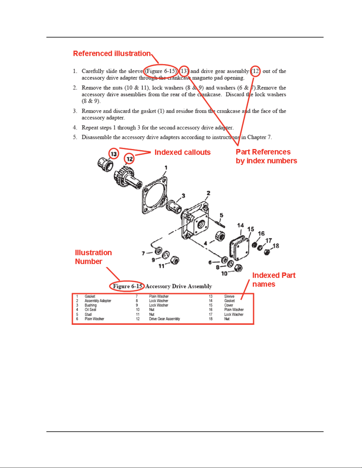
Introduction
Figure 1-1. Figure and Index Reference
Standard Practice Maintenance Manual 1-5
15 Sep 2019
Page 28

Introduction
1-1.5. Compliance
The owner/operator is responsible for ensuring the engine is maintained in an airworthy
condition, including compliance with FAA Airworthiness Directives. Engine service life
is calculated based on compliance with the aircraft and engine manufacturer’s required
instructions, inspections, and maintenance schedule. Failure to comply may void the
engine warranty.
Prior to authorizing engine maintenance, the owner must
ensure the facility or mechanic meets the Federal Aviation
Administration (or equivalent authority) regulatory
requirements. The engine owner must verify the repair facility
or mechanic uses the most current revision, including change
pages of the applicable ICA. Use of Instructions for Continued
Airworthiness which have been designated as obsolete,
superseded, or inactive is prohibited.
Continental ICAs are written for use by maintenance personnel who possess and apply the
knowledge, training, and experience commensurate with persons holding a valid license
or certification granted by the governing airworthiness authority to return the engine to an
airworthy condition. No other use is authorized.
WARNING
WARNING
Failure to comply with ICAs may result in personal injury,
death and subsequent engine failure. Each person performing
maintenance, alteration or preventive maintenance on an
engine or accessory must use methods, techniques and practices
set forth in the Instructions for Continued Airworthiness or
other methods, techniques, and practices found acceptable to
the Administrator.
This manual shall be used in conjunction with the latest revision of FAA Advisory
Circular 43.13-1, “Acceptable Methods, Techniques, and Practices” as well as related
publications and accessory manufacturer’s instructions. Pursuant to Title 14 CFR Part 43,
§43.13(a), each person performing maintenance, alteration, or preventive maintenance on
the engine or accessories must use methods, techniques, and practices prescribed in the
ICAs or other methods, techniques, and practices found acceptable by the Administrator.
1-6 Standard Practice Maintenance Manual
15 Sep 2019
Page 29

1-1.6. Order of Precedence
Continental engine operating instructions are generated prior to and independently of the
aircraft operating instructions. Continental operating instructions are developed using
factory controlled parameters that are not necessarily the same as those specifications
required to satisfy a specific aircraft/engine installation.
The aircraft operator must use the aircraft manufacturer’s
operating instructions found in the Airplane Flight Manual/
Pilot’s Operating Handbook (AFM/POH) and applicable
Airplane Flight Manual Supplements (AFMS) while operating
the engine in the aircraft unless the AFM/POH directs
otherwise.
Refer to the AFM/POH published by the aircraft manufacturer for operating instructions
and specifications relative to your aircraft.
Prior to commencing engine maintenance, consult the Continental web site
(www.continental.aero) to verify the current status of the ICAs relating to the intended
procedure.
Introduction
WARNING
1-2. Publications
This most current approved version of this manual is delivered to the customer at time of
purchase. This manual and all subsequent revisions or changes are published in Adobe
portable document format (PDF) and available to view or download from Aircraft
Technical Publishers (ATP) web site (www.atp.com).
1-2.1. Publication Access
Printed technical publications may be ordered through Continental technical publications
distributor, Aircraft Technical Publishers (ATP). Contact an ATP customer service
representative to discuss service subscription options and pricing or visit their web site
(www.atp.com).
1-2.2. Publication Changes
Use only the latest revision of all publications. Using superseded
information may jeopardize engine airworthiness. Service
documents, published by the manufacturer, or Airworthiness
Directives, published by the FAA, may alter or provide
supplemental information to the Maintenance and Overhaul
Manual. Verify and use only the current versions of all
instructions.
WARNING
The instructions in this manual represent the best and most complete information available
at the time of publication. Product or process improvements may trigger changes to
existing product design specifications or procedures contained in publications. As new
technical information becomes available, Continental will make the information available
to the customer.
Standard Practice Maintenance Manual 1-7
15 Sep 2019
Page 30
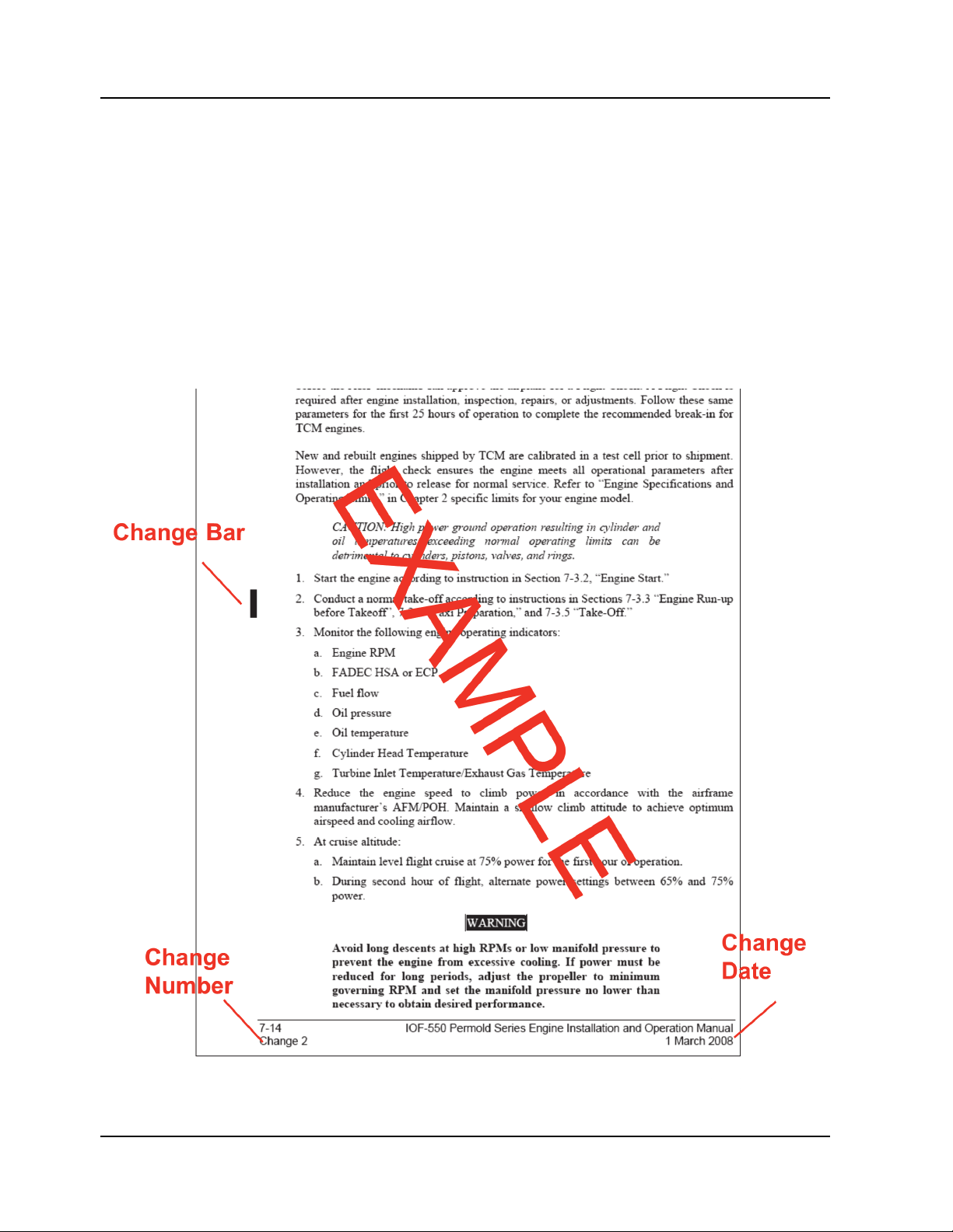
Introduction
Continental releases publication changes in the form of either change pages or complete
publication revisions, depending upon the extent of change.
Continental issues service documents in the form of Service Bulletins on a wide variety of
topics. Some service documents may affect or supplement information in this manual and
should be reviewed prior to performing maintenance. All active service documents
applicable to standard maintenance practices have been incorporated in these instructions
as of the date of publication.
1-2.3. Update/Change Distribution
Document updates are available on our web site upon notification of FAA document
acceptance/approval. Printed publication subscribers receive printed changes and
revisions as they are released.
Figure 1-2. Change Page Identification
1-8 Standard Practice Maintenance Manual
15 Sep 2019
Page 31

Introduction
Document revisions are released if the update changes more than 50% of the contents of a
publication. Revisions replace the previous version of a publication from cover to cover.
Minor corrections are released as change pages to the original publication, identified with
a change number and effective change date in the page footer. Information on the page that
changed from the previous edition is identified by a vertical, six-point black line
(Figure 1-2), referred to as a “change bar” in the outside margin of the page.
A change page replaces only the previous edition of the affected page. In the event a
change page forces repagination, a new page will be inserted with a decimal extension
added to the page number. For example, if additional pages are required between pages 16 and 1-7, the inserted page numbers will be 1-6.1, 1-6.2, and so on until sufficient pages
are added to incorporate the new material.
Page A of the manual contains the original publication date and an itemized list of changes
issued for the technical manual (Figure 1-3). If change pages are issued for the manual, the
change will be identified, with an effective date under the heading “Effective Changes for
This Manual” on Page A. The list of effective pages, itemizes the pages in each section, by
change number. Original pages are designated by a 0 in the List of Effective Pages
“Change” column.
Figure 1-3. List of Effective Pages
Standard Practice Maintenance Manual 1-9
15 Sep 2019
Page 32

Introduction
1-2.4. Service Documents
Continental may issue Service Documents in one of six categories ranging from mandatory
(Category 1) to informational (Category 6). Definitions of the categories are listed below:
NOTE: Upon FAA approval, Continental publishes service documents for
immediate availability on our web site. The service document cover page
indicates the engine models affected by the service document. Service
documents may alter or replace the manufacturer’s Instructions for
Continued Airworthiness. Insert a copy of applicable Service Documents
in affected manuals until the service document instructions are
incorporated in the manual, or the service document is canceled or
superseded.
1Procedure
Category 1: Mandatory Service Bulletin (MSB)
Used to identify and correct a known or suspected safety hazard which has been incorporated in whole or in
part into an Airworthiness Directive (AD) issued by the FAA or have been issued at the direction of the FAA
by the manufacturer requiring compliance with an already-issued AD (or an equivalent issued by another
country’s airworthiness authority). May contain updates to Instructions for Continued Airworthiness to
address a safety issue.
Category 2: Critical Service Bulletin (CSB)
This category identifies a condition that threatens continued safe operation of an aircraft, persons or property
on the ground unless some specific action (inspection, repair, replacement, etc.) is taken by the owner or
operator. Documents in this category are candidates for incorporation into an FAA Airworthiness Directive.
May contain updates to Instructions for Continued Airworthiness to address a safety issue.
Category 3: Service Bulletin (SB)
Information which the product manufacturer believes may improve the inherent safety of an aircraft or
aircraft component; this category includes the most recent updates to Instructions for Continued
Airworthiness.
Category 4: Service Information Directive (SID)
The manufacturer directs the owner/operator/mechanic in the use of a product to enhance safety,
maintenance or economy. May contain updates to Instructions for Continued Airworthiness in the form of
maintenance procedures or specifications.
Category 5: Service Information Letter (SIL)
This category includes all information (not included in categories 1 through 4) that may be useful to the
owner/operator/technician. May contain updates to Instructions for Continued Airworthiness for optional
component installations, which are not covered in the Applicable Operator, Maintenance, or Overhaul
Manuals.
Category 6: Special Service Instruction (SSI)
This category is used to address an issue limited to specific model and/or serial number engines. We will
distribute SSI notification directly to the affected engine’s owners.
service document set but will be made available through our Customer Service Department to owners of the
affected engines only. An SSI may update the applicable engine’s Instructions for Continued Airworthiness.
SSIs will not be included in the general
1-10 Standard Practice Maintenance Manual
15 Sep 2019
Page 33

Introduction
1-2.4.1. Service Documents Incorporated in this Manual
Applicable technical maintenance and service information contained in the Service
Documents listed below, relevant to the engine models covered by this engine manual,
have been incorporated in this M-0, Standard Practice Maintenance Manual. This manual
supersedes and retires these Service Documents (and all revisions, where applicable)
excluding Mandatory Service Bulletins (MSBs) and Critical Service Bulletins (CSBs)
identified with an asterisk (*) in Table 1-1 below.
The full content of active Continental Service Documents is available at
www.continental.aero. Refer to Section 1-3, “Contact Information” for Continental web
site details.
Table 1-1. Service Documents Incorporated in Manual
Affected
Service Document Subject
M67-12, Overboost of Turbocharged Engines Unscheduled Maintenance 6
M71-21, Procedure for Freeing Turbocharger Turbine Shafts which
are Dragging or Frozen by Rust Deposits
Troubleshooting 8
Chapter
M72-17R1, Maximum Weight Difference Between Connecting Rods
and Pistons in the Same Engine
M75-7R1, Oil Filter Change Scheduled Maintenance 6
M76-4, Propeller Shaft or Crankshaft Oil Seal Replacement Unscheduled Maintenance 10
M76-8, Intake Valve Change Unscheduled Maintenance 10
M76-20, Oil Filters Scheduled Maintenance 6
M77-3, Use of Alternate Fuels in Engines Originally Certified for 80/
87, 91/96 and 100/130 Grade Fuels
M81-28R1, Oil Filters Scheduled Maintenance 6
M84-5, Gear Driven Alternator Inspection Procedure Alternator Replacement 10
M85-10, Cylinder Hold Down Nuts Cylinder Replacement 10
M87-15, Alternator Ground Strap Alternator Replacement 10
* M88-4, Pro-Tech Oil FIlter Scheduled Maintenance 6
M88-9, Lightning Strikes Unscheduled Maintenance 6
M88-10, Contaminated Fuels Unscheduled Maintenance 6
M89-7R1, Engine Operation after Cylinder Replacement and/or
Major Overhaul
M89-9, Excessive Crankcase Pressure Unscheduled Maintenance 8
M90-17, Crankcase Inspection Criteria Scheduled Maintenance 6
SIL93-11B, Service Document Format Service Documents 1
Parts Replacement 10
Engine Operation 7
Unscheduled Maintenance 7
SIL93-15, General Practices for Installation of Lock Wire, Tab
Washers, and Cotter Pins
SB94-2, Oil Filter Adapter Mounting Stud Scheduled Maintenance 6
SIL94-5, Mobil AV1 Oil Engine Oil Specifications 3
Standard Practice Maintenance Manual 1-11
1 Feb 2021 CHANGE 1
Standard Practices Appendix C
Page 34

Introduction
Table 1-1. Service Documents Incorporated in Manual
Affected
Service Document Subject
SIL94-5, Mobil AV1 Oil Engine Oil Specifications 3
* MSB94-8D, Magneto to Engine Timing Scheduled Maintenance 6
SB95-2, Inspection and Maintenance of Engine Control Cables and
Linkage
SB95-3B, Alternator/Generator Drive Coupling Alternator Maintenance 6, 10
SIL95-5, Hose and Tubing Installation Hose and Tubing Installation Appendix C
SB96-7D, Torque Limits Fastener Torque Appendix B
* MSB96
SB96-11B, Propeller Strikes and Hydraulic Lock Unscheduled Inspection 6
SB96-12, Cylinder Continued Airworthiness Scheduled Inspection 6 & 10
SID97-2B, Design, Operation Maintenance and Warranty of
Cylinders
-10B, Crankshaft Ultrasonic Inspection Engine Overhaul or
Inspection 6
Crankshaft Repair
Engine Maintenance 6
Chapter
10
SID97-3G, Continuous Flow Fuel Injection Systems Adjustment
Specifications and Instructions
SID97-4F, Cylinder Bore and Piston Fit Specifications Overhaul & Service Limits 10
SB97-6B, Mandatory Replacement Parts Engine Inspection & Assembly Appendix C
SB97-11, Installation of Single Piece Rocker Assembly Bushings
Part Numbers 652129 and 652963
SIL98-9E, Time Between Overhaul Periods Scheduled Maintenance 6
SIL99-1, Engine Preservation for Active and Stored Aircraft Engine Preservation and
SIL99-2C, Sealants, Lubricants and Adhesives Authorized by CMI Materials 3
SB00-3A, Crankshaft, Counterweight and Connecting Rod Repair
Information
SIL00-9A, Engine Data Plates Data Plate Replacement Appendix C
SIL00-11B, Release of new Cylinder Induction Port Drain Connector Cylinder Assembly 10
SIL03-1, Cold Weather Operation - Engine Preheating Engine Operation 7
SIL03-2C, Currently Active Approved Spark Plug Application Spark Plugs 6
SB03-3, Differential Pressure Test and Borescope Inspection Inspection Criteria 6
SIL04-12A, Authorized Engine Adjustments, Component
Replacement and Repositioning
Operational Checks and
Adjustments
Cylinder Repairs 10
Recovery
Repair Specifications 10
Engine Specification 5
6
9
SID05-1B, Inspection Guidelines for Camshafts and Hydraulic Lifters Unscheduled Maintenance 6
SB05-2, Overspeed Limitations Unscheduled Maintenance 6
*CSB08-3C, Throttle & Mixture Control Levers Fuel Injection System
Assembly
SB08-13, Induction System Hose and Clamp Installation Induction System Inspection &
Assembly
1-12
CHANGE 3
Standard Practice Maintenance Manual
6 January 2023
6
6
Page 35

Introduction
Table 1-1. Service Documents Incorporated in Manual
Affected
Service Document Subject
SB11-3, Alternator and Drive Coupling Installation Alternator Replacement 6, 10
SIL13-2A, Alternator Instructions for Continued Airworthiness Alternator Replacement 6, 10
SB14-8, Exhaust Flange to Cylinder Installation Exhaust System Installation 10
SB16-3, Turbocharger Check Valve Inspection and Cleaning Exhaust System Inspection 6
SB17-01A, Flanged Nut Inspection and Corrosion Prevention Cylinder Inspection 6
SIL17-02, Turbocharger Check Valve Filter Installation, Inspection,
and Cleaning
SIL17-03, Oil Filter Anti-stick Gasket Oil and Filter Change 6
SIL18-01, Rocker Assembly Valve, Exhaust (P/N 658745) Rocker Arm Identification 10
SIL19-04, Oil Brand Selection Oil Servicing 6
SB19-05, Valve Guide Application, Installation, and Reaming
Procedures
SIL19-10, Disposable Oil Filter Removal Oil and Filter Change 6
SIL21-04A, Improved Rocker Cover Gasket, Part No. 668893 Cylinder Maintenance 10,
* Documents remain active in the service bulletin set.
Maintenance Criteria 6, 8,
Cylinder Maintenance 10
Chapter
Appendix C
Appendix B
1-2.4.2. Service Documents Released After Publication
Continental strives to provide clear, concise, and accurate information and instructions
based on best known engineering data at the time of publication. Ongoing process
improvements may change a specification or procedure after a manual is released. Service
documents, defined in Section 1-2.4, expedite customer notification until the new
information is incorporated in the manual text. As service documents are received, note
the service document number, release date, title, and applicable section affected by the
service document in the blank cells below and insert a copy of the service document
behind the last page of this section. Make pen & ink corrections, where appropriate, to the
original text in the manual with a citation to the service document; i.e. see SB9X-1. For
paragraphs or entire sections, draw an “X” through the affected information in the manual
and reference the service document containing the correction
Service Documents Release After This Manual
Document Number: Release Date:
Title:
Document Number: Release Date:
Title:
Document Number: Release Date:
Title:
Document Number: Release Date:
/ /
/ /
/ /
/ /
Affected Sections:
Affected Sections:
Affected Sections:
Affected Sections:
6 January 2023
1-13Standard Practice Maintenance Manual
CHANGE 3
Page 36

Introduction
Service Documents Release After This Manual
Document Number: Release Date:
Title:
Document Number: Release Date:
Title:
Document Number: Release Date:
Title:
Document Number: Release Date:
Title:
Document Number: Release Date:
Title:
Document Number: Release Date:
Title:
Document Number: Release Date:
Title:
Document Number: Release Date:
/ /
/ /
/ /
/ /
/ /
/ /
/ /
/ /
Affected Sections:
Affected Sections:
Affected Sections:
Affected Sections:
Affected Sections:
Affected Sections:
Affected Sections:
Affected Sections:
Title:
Document Number: Release Date:
Title:
Document Number: Release Date:
Title:
Document Number: Release Date:
Title:
Document Number: Release Date:
Title:
Document Number: Release Date:
Title:
Document Number: Release Date:
Title:
Document Number: Release Date:
Title:
/ /
/ /
/ /
/ /
/ /
/ /
/ /
Affected Sections:
Affected Sections:
Affected Sections:
Affected Sections:
Affected Sections:
Affected Sections:
Affected Sections:
1-14 Standard Practice Maintenance Manual
15 Sep 2019
Page 37

1-2.5. Related Publications
The table below lists the publications, source, and accessibility relevant to Standard
Practice installation, maintenance, and overhaul.
Use only the latest revision of all publications. Using superseded
information can jeopardize engine airworthiness.
CAUTION: Instructions in M-0, Standard Practice Maintenance Manual, do
not apply and shall not be used to maintain Continental Prime or Titan
engine products.
Introduction
WARNING
1
Supplied
With Engine
Electronic
Download
Available
Printed
Manual
Available
Document Part
Number (P/N)
Table 1-2. Related Publications
Publication Title
Instructions for Continued Airworthiness
M-0
s manual)
(thi
Standard Practice Maintenance Manual
2
Yes Yes Yes
X30531 Alternator Service Support Manual Yes Yes Yes
X42001 Magneto Service Support Manual (S-1200 Series) Yes Yes Yes
X42002 Magneto Service Support Manual (S-20/200 Series) Yes Yes Yes
Illustrated Parts Catalogs
by Engine
Model/
Electronic Engine Product Catalog No Yes (view only) No
Specification
1. Our web site (www.continental.aero) provides daily 24-hour access to current service documents and the technical publications Index.
Continental is partnered with Aircraft Technical Publishers (ATP, (www.atp.com) to distribute our technical publications on their subscription
web site. If you have not subscribed to ATP and are using printed manuals, verify & confirm you have the latest applicable revision with
either a service representative (using the “Contact Information” in Section 1-3) or the Service Document Index.
2. Instructions in M-0, Standard Practice Maintenance Manual, do not apply and shall not be used to maintain Continental Prime or Titan
engine products.
1-2.5.1. Suggestions and Corrections
Continental solicits and encourages user comments regarding suggested changes to this
manual. Direct recommended changes or questions to the attention of “Publications” at the
address listed in Section 1-3, “Contact Information” or send comments via e-mail to
cm.techpubs@continental.aero.
Notify our Customer Service Department immediately if you discover incorrect
information which adversely affects safety.
Standard Practice Maintenance Manual 1-15
15 Sep 2019
Page 38

Introduction
1-3. Contact Information
Continental factory representatives are available to answer technical questions and
encourages suggestions regarding products, parts, or service. If customers have an inquiry
or require technical assistance, they should contact their local Continental distributor or
field representative. To contact a factory representative, refer to the contact information
below:
Continental Aerospace Technologies
P. O. Box 90
Mobile, AL 36601
Customer Service Department:
Toll free within the continental United States: 1-888-826-5465
International: 1-251-438-8299
Internet: www.continental.aero
1-4. Service Parts
Continental engineering staff develops a complete bill of materials for every engine model
specification manufactured. Due to our diverse customer base of aircraft OEM and STC
application builders, engine model specifications are developed to accommodate the
aircraft manufacturer’s specifications. While many parts fit multiple engine model
specifications, interchangeability of parts from one engine model, or model specification,
to another is not guaranteed.
1-4.1. Service Part Applicability and Availability
Major engine assemblies and components are permanently identified (steel stamped,
engraved, laser etched, or ink-stamped) with a unique part number during the
manufacturing process. The latest revision of the Illustrated Parts Catalogs is available on
our web site to locate Continental parts for current production engine model specifications
and heritage products (no longer in production).
Some parts of assemblies are not available for aftermarket sale for various reasons. Some
assemblies are not intended to be disassembled, such as cylinder heads and barrels. For
this reason, only the next higher assembly (NHA) is available for aftermarket sales.
1-4.2. Part Supersedure
Innovation and continuous improvements are core values at Continental. The original part
numbers used to manufacture your aircraft engine may or may not be available when
replacement parts are needed to restore the engine to an airworthy condition. Due to
design improvements to the form, fit, or function of the engine part or assembly, it may be
necessary to supersede the older part number (used to build the original engine model
specifications) and provide a new replacement part or assembly number.
The simplest way to determine the correct part number can be found by comparing the
markings on the existing part(s) to part numbers in the Illustrated Parts Catalog (IPC).
To determine if a part number used to assemble your engine has been superseded, consult
the Parts Supersedure History page on our web site.
1-16 Standard Practice Maintenance Manual
15 Sep 2019
Page 39

2-1. Special Tools
NOTE: Special tools listed in Table 2-1 are for reference only, not for the
purpose of promoting or requiring the customer to purchase from a
particular provider. The providers listed are potential sources for the
items based on information available at the time of printing. Customers
are free to obtain equivalent items from alternate sources which meet or
exceed specifications of the listed tools. For FADEC special tools,
reference the primary ICA.
Special tool vendor contact information is listed in Table 2-2.
Tools
Chapter 2. Tools
Table 2-1. Special Tools List
Special Tool Use or Reference Suggested Providers Part Number
Maintenance
0-60 psi Pressure
Gauge (graduated in 1-
Engine Operational Check Davis Instruments Various
psi increments)
0-30 psi Pressure
Gauge (graduated in
0.2-psi increments)
Engine Operational Check
(normally aspirated engines only)
Davis Instruments Various
0-30 psid Differential
Pressure Gauge
(graduated in 0.2 psi
Engine Operational Check
(turbocharged engines only)
Davis Instruments Various
increments)
Alternator Drive Hub
Spanner Wrench
Alternator Drive Hub
Torque Tool
Alternator Drive Hub
Torque Tool
Bearing Installation Tool
(Worm Gear Roller
Bearing)
Forward Mounted Alternator Drive Hub
Assembly Inspection
Forward Mounted Alternator Drive Hub
Slippage Inspection
Aft Mounted Alternator Drive Hub Slippage
Inspection
90° offset Starter Adapter Assembly
Ideal Aviation 9001-IA
Fabricate according to
Figure 2-5
Fabricate according to
Figure 2-6
Fabricate according to
Figure 2-15
---
---
---
Belt Tension Gage Drive Belt Tension Adjustment Ideal Aviation BT-33-73FIA
AUTOSCOPE
Borescope Cylinder Borescope Inspection Q.A. Technologies
Lenox Instrument
Company
Differential Pressure
Tester
Cylinder Differential Pressure Test
Digital Multimeter Troubleshooting
High Tension Lead Test
Kit
Ignition Harness Troubleshooting
Eastern Technology
Corporation
Commercial, off the
shelf
Eastern Technology
Corporation
Model E2M
---
E5
7/16” Injector Nozzle
Removal/Installation
Fuel Injector Removal And Installation Ideal Aviation 8167-IA
Tool
1
TM
Standard Practice Maintenance Manual 2-1
1 Feb 2021 CHANGE 1
Page 40

Tools
Table 2-1. Special Tools List
Special Tool Use or Reference Suggested Providers Part Number
1/2” Injector Nozzle
Removal/Installation
Fuel Injector Removal And Installation Ideal Aviation 8168-IA
Tool
Aircraft Tool Supply AA470
Oil Filter Can Cutter Cut Oil Filter Can
Aircraft Tool Supply FC-2000
Champion Aerospace CT-923
Oil Filter Torque Wrench Oil Filter Installation
Oil Strainer, 1000
Micron
Oil Change Arbor Fabrication 2000
Porta-Test Unit Engine Operational Check
Portable Digital EGT/
CHT Tester
Verify EGT/CHT/TIT Accuracy Alcor, Inc. ALCAL 2000
Protractor/Timing
Indicator Disc and
Engine Timing
TDC Locator
Aircraft Tool Supply AA472
Champion Aerospace CT-921
Approved Aircraft
Accessories (Aero Test)
Eastern Technology
Corporation
Model 20 ATM-C
E25
Pulley Alignment Tool Belt Drive Pulley Alignment Ideal Aviation 8082-IA
Pulley Puller Remove Generator/Alternator Sheave Ideal Aviation 61-5IA
Timing Light Magneto to Engine Timing
Worm Shaft Tool &
Starter Adapter
Starter & Starter Adapter Disassembly
Disassembly Tool
Eastern Technology
Corporation
Fabricate according to
Figure 2-7
E50
---
1
Overhaul
Bearing Puller Component Maintenance Borroughs*** 8093C
Boring Bars Cylinder Repair Borroughs***
Carbide Tipped Reamer Valve Guide Reaming Kent-Moore***
8116-1B through 15B
2847-2CP
2847-1CP
Common Drive Handle Cylinder Repair Borroughs*** 8122A
Common Parts Kit Valve Seat Replacement Borroughs*** 8116
Connecting Rod Boring
& Alignment Fixture
Connecting Rod
Bushing Removal/
Installation Set
Connecting Rod Piston Bushing
Replacement
Connecting Rod Piston Bushing
Replacement
Borroughs*** 8111A
Borroughs*** 8098
Connecting Rod
Bushing Installation and
Removal Tool Adapter
Connecting Rod Piston Pin Bushing
Replacement
Borroughs*** 8042C
Kit
Connecting Rod
Bushing Reamer
Connecting Rod Bushing Bore Honing
Contact Profilometer Cylinder Bore Honing
Kent-Moore*** 5008
Borroughs*** 8071
Commercial, off the
shelf
N/A
2-2 Standard Practice Maintenance Manual
CHANGE 1 1 Feb 2021
Page 41

Table 2-1. Special Tools List
Tools
Special Tool Use or Reference Suggested Providers Part Number
Counterweight Bushing
Remover/Replacer Tool
Crankcase Needle
Bearing Installer Tool
Counterweight Hanger Blade Bushing
Replacement And Counterweight Bushing
Replacement
Crankcase Assembly
Borroughs*** 4965A
Fabricate according to
Figure 2-16 (Permold)
---
Figure 2-17 (Sandcast)
Crankcase Splitter Separate The Crankcase Kent-Moore*** L423
Crankcase Through
Bolt Remover
Crankcase Disassembly Borroughs*** 8114-8
Crankshaft
Counterweight Bushing
Removal/Installation
Crankshaft Overhaul Borroughs*** 8077C
Fixture
Crankshaft Hanger
Blade Bushing
Removal/Installation
Crankshaft Overhaul Borroughs*** 8077A
Tool
Crankshaft Nose Oil
Seal Installer Tool
Crankshaft Nose Oil Seal Installation
Not require for split type nose oil seals
Kent-Moore*** 5209
5203, 5204, &
Cylinder Base Nut
Wrenches
Cylinder Maintenance
Kent-Moore***
8158A, 3882, &
3882-2
Borroughs*** 8079
Cylinder Heating Stand Cylinder Maintenance Borroughs*** 8156
Valve Seat Replacement
Cylinder Holding Fixture
Valve Guide Replacement
Borroughs*** 5221B
Valve Seat Machining
Cylinder Holding Fixture
Adapters
Valve Seat Replacement
Valve Guide Replacement
Valve Seat Machining
Borroughs***
5221-13A
5221-15A
5221-16A
Cylinder Hone Engine Cylinder Bore Honing Snap On Tools CFL10
Dial Indicator Gear Backlash Measurement
Commercial, off the
shelf
---
Exhaust Valve Seat
Grinding Stone
Valve Seat Machining Aircraft Tool Supply K95
(Roughening 45)
Exhaust Valve Seat
Grinding Stone
Intake Or Exhaust Valve Seat Machining Aircraft Tool Supply K25
(Finishing 45)
Expanding Guide
Bodies
Valve Guide Replacement Borroughs***
8116-1 through -
16
Generator Drive Holder Secure The Generator Drive Borroughs*** 4973
Heli-Coil Extracting Tool Helical Coil Insert Replacement
Heli-Coil Installation
Tool
Heli-Coil Expanding
Tool No. 520-2
Helical Coil Insert Replacement
Helical Coil Insert Replacement
Stanley Engineered
Fastening
Stanley Engineered
Fastening
Stanley Engineered
Fastening
---
---
520-2
1
Standard Practice Maintenance Manual 2-3
1 Feb 2021 CHANGE 1
Page 42

Tools
Table 2-1. Special Tools List
Special Tool Use or Reference Suggested Providers Part Number
High Speed Steel
Reamer
Reaming Valve Guides Kent-Moore***
2847-1HP
2847-2HP
Intake Valve Seat
Grinding Stone
Valve Seat Machining Aircraft Tool Supply K106
(Roughening 30)
Intake Valve Seat
Grinding Stone
Valve Seat Machining Aircraft Tool Supply K46
(Finishing 30)
Needle Bearing Installer
Tool
O-ring Installation Tool Crankcase Hardware Installation
Oil Control Plug
Installation Tool
Oil Control Plug Leak
Test Fixture
Oil Pressure Relief Spot
Facer
Oil Seal Tool
Piston Ring
Compressor
Starter Adapter Housing Worm Shaft Needle
Bearing Replacement
Borroughs*** 23-1
Fabricate according to
Figure 2-19
---
Fabricate according to
Oil Control Plug Replacement
Figure 2-10 through
---
Figure 2-11
Oil Control Plug Replacement
Fabricate according to
Figure 2-12
---
Oil Pressure Relief Valve Seat Refacing Kent-Moore*** 8048
Crankcase And Accessory Drive Adapter Oil
Seal Installation
Fabricate according to
Figure 2-20
---
Engine Cylinder Installation Kent-Moore*** 3601
Piston Ring Removers Piston Ring Removal Kent-Moore*** 8121
Polishing Tool Engine Drive Train Inspection Burroughs*** 8087B
Pushrod Spring
Compressor Tool
Reamers Valve Guide Reaming Borroughs***
Reamer, Adjustable
Blade
Rocker Arm Bushing
Remover/Installer
Rocker Arm Bushing
Reamer
Rosan
Rosan
Stud Remover
Lock Ring
Installer
Spark Plug Insert
Remover
Spark Plug Insert
Replacer
Spark Plug Tap
(18 mm)
Pushrod Installation Kent-Moore 68-3
8116-1R through 15R
Magneto Drive Adapters Bushing And Oil
Seal Installation
Rocker Arm Bushings (Single-Bushing
Type) Replacement
Borroughs***
Kent-Moore*** 8118
Size range 2513227132
Ream Rocker Arm Bushing Kent-Moore*** 7232
Remove Rosan Studs
McMaster-Carr Supply
Company
2769A13
Rosan Studs Installation Kent-Moore*** 8074
Spark Plug Heli-coil Insert Removal Borroughs*** 4919
Spark Plug Heli-coil Insert Installation Borroughs*** 4918
Repair Damaged Spark Plug Threads/Boss Borroughs*** 445
Test Club Post-Overhaul Testing Hartzell Propeller, Inc.
1
2-4 Standard Practice Maintenance Manual
CHANGE 1 1 Feb 2021
Page 43

Table 2-1. Special Tools List
Tools
Special Tool Use or Reference Suggested Providers Part Number
Valve Guide Boss
Reamers
Valve Guide Floating
Holder
Valve Guide Reaming Kent-Moore***
Valve Guide Replacement Borroughs*** 3170
4943-1 HS
through -5HS
Valve Guide Remover Valve Guide Replacement Kent-Moore*** 4981
Valve Guide Seal
Installation Tool
Valve Seat Grinder Set
“Sioux Brand”
Valve Seat Grinder Pilot
0.437 diameter
Valve Seat (Straight
Side) Insert Cutters
Valve Seat (Step Side)
Insert Cutters
Valve Seat Insert
Remover & Replacer
Valve Spring
Compressor Tool
Valve Guide Seal Installation
Machining Intake Or Exhaust Valve Seat Aircraft Tool Supply 1675
Machining Intake Or Exhaust Valve Seat Aircraft Tool Supply AEX 437
Valve Seat Repair Kent-Moore*** 5224 & 5225
Valve Seat Repair Kent-Moore***
Valve Seat Replacement Borroughs*** 8086
Engine Cylinder Assembly Kent-Moore*** 3602
Fabricate according to
Figure 2-18
---
8135, 8136, &
8138
Overhaul Inspection
Contour Probe Magnetic Particle Inspection
Parker Research
Corporation
DA-200
Federal Dimension Air
Gage (with setting ring
and air plug) or
equivalent with
1.1268 Setting Ring
Counterweight Hanger Blade Bushing
Replacement
Counterweight Bushings Replacement
MAHR Federal D-4000
1.1268 Air Plug
Dial Bore Gauges
Cylinder Bore Inner Diameter Dimensional
Inspection
MAHR Federal 545-116
Plug Gauge Cylinder Intake Valve Guide Inspection Kent-Moore*** 2848-1
Krautkramer-
Branson P/N:
Ultrasonic Test
Instrument, Portable
Crankshaft Ultrasonic Inspection Krautkramer-Branson
USK 7D OR7S
USL 42
USL 48
USN 50
USN 52
Ultrasonic Test
Instrument Calibration
Block
Coaxial Cable - Grade
74 RG174/U 50 ohm
Microdot to BNC (6’)
Coaxial Cable MMD to
BNC (6’)
Crankshaft Ultrasonic Inspection
(Equipment Calibration)
Krautkramer-Branson
Crankshaft Ultrasonic Inspection
(For Connecting The Transducer To The
Krautkramer-Branson
Ultrasonic Equipment)
Cylinder Barrel Ultrasonic Inspection Krautkramer-Branson
DSC Block or
Rompas Block
(steel)
Krautkramer-
Branson P/N
118140012
Krautkramer-
Branson P/N
C-047
1
Standard Practice Maintenance Manual 2-5
1 Feb 2021 CHANGE 1
Page 44

Tools
Table 2-1. Special Tools List
Special Tool Use or Reference Suggested Providers Part Number
Filter (microhenry BNC
to BNC)
Cylinder Barrel Ultrasonic Inspection Krautkramer-Branson
KrautkramerBranson P/N 281678-200
Krautkramer-
Fixture 60 Axial Cylinder Barrel Ultrasonic Inspection Krautkramer-Branson
Branson P/N
291-678-000
Krautkramer-
Flaw Detector Cylinder Barrel Ultrasonic Inspection Krautkramer-Branson
Branson P/N USL42 or equivalent
Krautkramer-
Transducer 5.0 MHz,
0.125 diameter
Cylinder Barrel Ultrasonic Inspection Krautkramer-Branson
Branson P/N
SMSWS 113-214585
Transducer, Miniature
(Gamma Series 5 MHz)
Crankshaft Ultrasonic Inspection
(Provide Piezoelectric Effect)
Krautkramer-Branson
KrautkramerBranson P/N
MSWS 224-580
Crankshaft Main
Bearing 2.2375 –
2.2485 inches (5.6833 –
Crankshaft Ultrasonic Inspection Continental 654478-1
5.7112 cm) and
Miniature Wedge
(45 shear wave)
Crankshaft Ultrasonic Inspection Continental 654484
Crankshaft Main
Bearing 2.3630 –
2.3750 inches (6.0020 –
Crankshaft Ultrasonic Inspection Continental 654483-1
6.0325 cm) and
Miniature Wedge
(45 shear wave)
Crankshaft Ultrasonic Inspection Continental 654578
Crankshaft Main
Bearing 2.6140 –
2.6250 inches
Crankshaft Ultrasonic Inspection Continental 654485-1
(6.6396 – 6.6675 cm)
and
Miniature Wedge
(45 shear wave)
Micrometers (series 3
point contact inside
micrometers)
Crankshaft Ultrasonic Inspection Continental 654484
Counterweight Hanger Blade Bushing
Replacement
Starrett No. 78
Runout Block Set Drive Train Dimensional Inspection Borroughs*** 8117a
*or equivalent
**Providers can be subject to change or discontinue manufacturing tools
*** The rights to manufacture Borroughs and Kent-Moore tools has been acquired by Kell-Strom Tool Company.
1
1. Items with Continental part numbers may be purchased directly from Continental.
2-6 Standard Practice Maintenance Manual
CHANGE 1 1 Feb 2021
Page 45

2-1.1. Vendor Contact Information
Table 2-2. Tools, Accessories, and Supply Vendors
Tools
Supplier Address Phone FAX Web Address
American Lubricants /
Moly Motor Oil
Aircraft Tool Supply
Alcor
Arbor Fabricating
A. W. Chesterton
Company
ASTM
1227 Deeds
Dayton, OH 45401
P.O. Box 370
1000 Old U.S. 23
Oscoda, MI 48750
300 Breesport
San Antonio, TX 78216
14030 Tuttle Hill
Milan, MI 48160
500 Unicorn Park Drive
Woburn, MA 01801-3345
100 Barr Harbor Drive
West Conshohocken, PA 19428
937-222-2851 618-534-5231 molymotoroil.com
800-248-0638
517-739-1447
800-343-7233
210-349-6491
517-739-1448 aircraft-tool.com
210-308-8536 alcorinc.com
734-626-5864 N/A arborfab.com
800-835-4135
781-438-7000
877-909-2786
610-832-9585
781-438-8971 chesterton.com
N/A astm.org
1
Borroughs See Kell-Strom Tools
Champion Aerospace,
Inc.
CRC Industries/Chemical
Products
Crown Equipment Corp.
Davis Instruments
Daubert Chemical
Dow Corning Corporation
1230 Old Norris Road
Liberty, SC 29657
885 Louis Drive
Warminister, PA 18974
44 S. Washington Street
New Bremen, OH 45869
625 E. Bunker Ct.
Vernon Hills, IL 60061
4700 South Central Ave Chicago,
IL 60638
P.O. Box 997
South Saginaw Road
Midand, MI 48686
864-843-1162 864-843-5402
800-272-4620
800-556-5074
800-272-4560
215-674-2196
championaerospace.co
m
crcindustries.com
419-629-2311 N/A crown.com
800-358-5525
inotek.com
davis.com
708-563-8325 78-496-7367 daubertchemical.com
989-496-4400
800-662-0661
dowcorning.com
Eastern Electronics See Eastern Technology Corporation
Eastern Technology
Corporation
42 Nelson St.
East Hartford CT 06108
860-528-9821 860-289-7639 easterntech.com
Federal Mogul Southfield, MI 248-354-7700 federal-mogul.com
Graham Aircraft Engines
(Motorstor)
Hartzell Engine
Technologies (formerly
Kelly Aerospace)
Hartzell Propeller Inc.
Henkel Aerospace
Ideal Aviation
PO Box 3214
Peachtree City, GA 30269
Plane Power
2900 Selma Hwy
Montgomery, AL 36108
One Propeller Place
Piqua, OH 45356
32100 Stephenson Hwy
Madison Heights, MI 48071
564 Juanita Avenue
Mesa, AZ 85204
770-252-4995 770-252-5270 www.highaero.com
877-359-5355 334-386-5410 hartzellenginetech.com
937-778-4200 937-778-4271 hartzellprop.com
248-583-9300 248-583-2976 henkel.com
480-963-8890 480-963-8887 idealaviation.com
Standard Practice Maintenance Manual 2-7
1 Feb 2021 CHANGE 1
Page 46

Tools
Table 2-2. Tools, Accessories, and Supply Vendors
Supplier Address Phone FAX Web Address
Kent-Moore See Kell-Strom Tool Company
metrologyworld.com/
storefronts/
krautkramer.html
Krautkramer-Branson
Loctite
LPS Laboratories
Lubriplate
MAHR Federal
McMaster-Carr Supply
Company
Merit Abrasives
Miller-Stephenson
Chemical Company
Q.A. Technologies
Plane Power®, see
Hartzell Engine
Technologies
Parker Research
Corporation
Shell Oil Company
50 Industrial Park Road
Lewistown, PA 17044
1001 Trout Brook Crossing
Rocky Hill, CT 06067-3910
4647 Hugh Howell Road
Tucker, GA 30084
129 Lockwood St.
Newark, NJ 07105
1144 Eddy Street
Providence, RI 02905
P.O. Box 4355
Chicago, IL 60680-4355
201 W. Mansville Dr.
Compton, CA 90224
6348 Oakton St.
Morton Grove, IL 60053
P.O. Box 61085
Savannah, GA 31420
Plane Power
2900 Selma Hwy
Montgomery, AL 36108
P.O. Box 1406
Dunedin, FL 34697
P.O. Box 2463
Houston, TX 77252
717-242-0327
334-438-3411
860-571-5100
800-243-4874
800-241-9334
770-243-8800
973-589-9150
800-733-4755
401-784-3271
800-343-2050
860-571-5465 loctite.com
770-243-8899 lpslabs.com
973-589-4432 lubriplate.com
401-784-3246 mahr.com
630-833-0300 630-834-9427 mcmaster.com
800-421-1936
310-639-4242
847-966-2022
800-992-2424
800-472-3094 meritabr.com
847-966-8468 miller-stephenson.com
912-330-0500 912-330-0104 qatek.com
877-359-5355 334-386-5410 hartzellenginetech.com
800-525-3935
727-796-4066
713-241-4819
800-332-6457
727-797-3941 parkreascorp.com
713-241-6511 shell-lubricants.com
Snap On (Tools) 877-740-1900 877-740-1880 snapon.com
Stanley Engineered
Fastening
L.S. Starrett Company
Tanair (Tanis Aircraft
Services)
U.S. Industrial Tool &
Supply
Worldwide Filter
(Mouse Milk)
4 Shelter Rock Lane
Danbury, CT 06810
121 Crescent Street
Athol, MA 01331
P14871 Pioneer Trail Suite. 200
Eden Prairie, MN 55347
14083 South Normandie Ave.
Gardena, CA 90249
1689 Abram Court
San Leandro, CA 94577
877-364-2781 800-225-5614
800-541-8887
978-249-3551
978-249-8495 starrett.com
stanleyengineeredfaste
ning.com
800-443-2136
In Minnesota:
952-224-4426 tanisaircraft.com
952-224-4425
310-464-8400
800-464-8400
310-464-8880 ustool.com
510-483-5122 734-455-3256 mousemilk.com
1
1. Unless otherwise indicated, type http://www. followed by the Web Address shown in tis column.
2-8 Standard Practice Maintenance Manual
15 Sep 2019
Page 47

Tools
Pressure
Regulator
Regulator
Pressure
Gauge
Cylinder
Pressure
Gauge
Master
Orifice
Valve
Slow Fill
Valve
Cylinder
Adapter
AIR
IN
Pressure
Regulator
Regulator
Pressure
Gauge
Cylinder
Pressure
Gauge
Master
Orifice
Valve
Slow Fill
Valve
Cylinder
Adapter
AIR
IN
Figure 2-1. Model E2M Differential Pressure Tester (built in Master Orifice Tool)
Figure 2-2. Borescope (Autoscope®)
NOTE: Borescopes are available from multiple manufacturers, with
varying levels of features and resolution. The Autoscope® is only one of
the available products.
Standard Practice Maintenance Manual 2-9
15 Sep 2019
Page 48

Tools
Figure 2-3. Pulley Alignment Tool
Figure 2-4. Porta-Test Model 20 ATM-C
2-10 Standard Practice Maintenance Manual
15 Sep 2019
Page 49

Tools
Figure 2-5. Gear Driven Alternator Drive Hub Torque Tool
Used on Permold 520/550 Permold Series Engines
Standard Practice Maintenance Manual 2-11
15 Sep 2019
Page 50

Tools
Figure 2-6. Alternator Drive Hub Torque Tool
Used on 200/300/240/360 Series Engines
Figure 2-7. Worm Shaft Tool and Starter Adapter Disassembly Tool
2-12 Standard Practice Maintenance Manual
15 Sep 2019
Page 51

NOTE: The Driver for the Oil Control Plug Installation Tool (Figure 2-8
through Figure 2-11) is the same for all installation tools/engine models.
Tools
Figure 2-8. Oil Control Plug Installation Tool - 360 Engines
Figure 2-9. Oil Control Plug Installation Tool - 470 Engines
Standard Practice Maintenance Manual 2-13
15 Sep 2019
Page 52

Tools
Figure 2-10. Oil Control Plug Installation Tool - 520/550 Permold Engines
Figure 2-11. Oil Control Plug Installation Tool - 470/520/550 Sandcast Engines
2-14 Standard Practice Maintenance Manual
15 Sep 2019
Page 53

Tools
Figure 2-12. Oil Control Plug Leak Test Fixture
Standard Practice Maintenance Manual 2-15
15 Sep 2019
Page 54

Tools
Figure 2-13. Needle Bearing Installation Tool - Part 1
2-16 Standard Practice Maintenance Manual
15 Sep 2019
Page 55

Tools
Figure 2-14. Needle Bearing Installation Tool - Part 2
Standard Practice Maintenance Manual 2-17
15 Sep 2019
Page 56

Tools
Figure 2-15. Bearing Installation Tool
2-18 Standard Practice Maintenance Manual
15 Sep 2019
Page 57

Tools
Crankcase needle bearing installation tools vary by the depth the needle bearing is
installed. The needle bearing installed depth for:
• Permold crankcases is 9/16” (see Figure 2-16, 0.625”)
• Sandcast crankcases is 1/2” (see Figure 2-17, 0.50”).
Figure 2-16. Crankcase Needle Bearing Installation Tool, Permold
Figure 2-17. Crankcase Needle Bearing Installation Tool, Sandcast
Standard Practice Maintenance Manual 2-19
15 Sep 2019
Page 58

Tools
Figure 2-18. Valve Guide Seal Installation Tool
2-20 Standard Practice Maintenance Manual
15 Sep 2019
Page 59

Figure 2-19. O-Ring Installation Tool
Medium Knurl
Mill Flat
Stamp P/N
On Flat
1/16 Radius
0.783 Dia.
1.200 Dia.
1.00
0.68
5/16
1-1/4 Dia.
Before Knurl
1/8x45°
1.00
2.00
3.00
Material 1020
Case Harden
Tools
Figure 2-20. Oil Seal Tool
Standard Practice Maintenance Manual 2-21
15 Sep 2019
Page 60

Tools
Figure 2-21. Helical Coil Extraction Tool
Figure 2-22. Helical Coil Insertion Tool
2-22 Standard Practice Maintenance Manual
15 Sep 2019
Page 61

Tools
Figure 2-23. Helical Coil Expanding Tool
Figure 2-24. Rosan® Stud Removal Tool
Standard Practice Maintenance Manual 2-23
15 Sep 2019
Page 62

Tools
2-2. Mechanic’s Tools
The tools listed below are required to perform overhaul procedures on the engines.
Table 2-3. Common Tools
Open-End Wrenches – 1/4-inch through 1-Inch 1/4-inch Slide hammer
Socket Wrenches:
1/4-inch drive
Socket Sizes: 5/32-inch through 1/2-inch
3/8-inch or 1/2-inch drive
Socket Sizes: 7/16-inch through 1-1/2-inch
Deep Well Sockets:
1/2-inch drive
Socket Sizes: 7/16-inch drive through 1-inch
Calibrated Torque Wrenches:
• 0 to 1000 in-lbs
• 0 to 500 in-lbs
• 0 to 100 ft-lbs
Micrometers Ball Peen Hammer
Allen Wrenches - assortment Pullers
Slotted Screwdrivers – assortment Blind Bearing Remover
Phillips Screwdrivers – Nos. 1 and 2 Vernier Calipers
Safety Wire Pliers Leather or soft plastic Mallet
Common Pliers Small hole gauges, thickness gauges
Diagonal Cutter Pliers Feeler Gauges (leaf-type)
Needle-Nose Pliers C-Clamps
Duck Bill Pliers Brass Wire Brush
Snap Ring Pliers (with 90-degree bend) Stiff-bristled, Non-wire Scrub Brush
Inspection light/flashlight Dry Blaster Cleaning Tool
Two-inch (2”) Merrit Wheel (flap wheel) Air Impact Tool
T-handle Drive Toolmaker’s Square
Magnifying Glass (10X power) Profilometer
Mirror Chamfer Tool
Utility Knife Morse Adapter
Scissors Heavy Duty Drill Press
Crimp Tool Arbor Press (and 8-inch arbors)
Wire Ties Vertical Mill
Ring Expander Engine Hoist
Bench Vise with Shielded Jaws Engine Stand
Fiber Drift, Brass Drift, Pin or Punch Transport dolly
Magnet Aircraft Tie-downs and Stop-blocks
Stud Extractor Tool V-blocks
Ezy Out Catch Basins (Fuel and Oil)
Wood or Plastic Spatula Permanent Marker
Tank Sprayer Strap Wrench
Ratchets:
• 1/4-inch drive
• 3/8-inch drive
• 1/2-inch drive
Heat Gun
(variable intensity/ equipped with a small tip)
• Drill, 0.266 (H) Pneumatic drill
• 00.339 Drill High speed borer
• Drill Index
2-24 Standard Practice Maintenance Manual
15 Sep 2019
Page 63

Chapter 3 . Lubricants, Sealants, and Adhesives
3-1. Engine Oil Specifications
WARNING
While it is unlikely any Mobil AV1 brand oil remains available,
in use, or in inventory, use of Mobil AV1 is prohibited from use
in Continental aircraft engines.
Lubricating oils qualified for use in Continental aviation gasoline (AvGas) engines are
required to meet Society of Automotive Engineers (SAE) specifications. SAE J1899 is the
specification for aircraft piston engine ashless-dispersant oil. SAE J1966 is the
specification for aircraft piston engine non-dispersant mineral oil.
Lubricating oil meeting these specifications is acceptable; proof of conformity is the
responsibility of the lubricant manufacturer.
Lubricating oil classified by North Atlantic Treaty Organization (NATO) or
Standardization Agreement (STANAG) as interchangeable with oils qualified under SAE
J1899 or SAE J1966 and assigned NATO codes O-123 or O-128 shall be considered
qualified.
The marketers listed in Table 3-1 have supplied data to Continental indicating the products
conform to one or more of the requirements above.
Lubricants, Sealants, and Adhesives
Continental recommended oil grades:
• Above 40°F ambient air, sea level SAE 50 or multi-viscosity
• Below 40°F ambient air, sea level SAE 30 or multi-viscosity
3-1.1. Oil Brand Selection
Reference: SIL19-04
CAUTION: Use the appropriate oil grade applicable to their specific
engine or product line and maintain a consistent oil brand to sustain
standard engine operations until after overhaul. Use only oil
specification approved by the engine Type Certificate Data Sheet.
Lubricant manufacturers produce multiple oil products which comply with specification
MHS-24; each containing proprietary formulations for straight weight and multiviscosity
oil grades. Operators choose the appropriate oil to service their engine based on
Instructions for Continued Airworthiness (ICAs), operating environment, viscosity, brand,
and personal preference. Switching oil brands before engine overhaul may result in higher
wear rates for lifters and cylinder components, even under normal operating conditions.
Analysis indicates consistent servicing with one brand of oil will result in fewer
maintenance events and more consistent oil analysis results. Continue using the same oil
brand throughout the service life of the engine. Do not change from an established “oil
type” (mineral oil, semi-synthetic oil), even within the selected brand, before engine
overhaul.
Standard Practice Maintenance Manual 3-1
1 Feb 2021 CHANGE 1
Page 64

Lubricants, Sealants, and Adhesives
Table 3-1. Qualified SAE J1899 Ashless Dispersant Engine Oil
Supplier Brand
Air BP Lubricants
ExxonMobil Aviation Exxon Elite
NYCO S.A. Turbonycoil 3570
Pennzoil Company
Phillips 66 Aviation
ConocoPhillips
Shell Aviation
Total Lubricants
Castrol Aviator AD Oil
Castrol Aviator A Oil
Pennzoil
Phillips 66 Type A 100 AD, 120 AD
Phillips 66 Victory Aviation Oil 100AW
Phillips 66 X/C Aviation Oil SAE 20W-50, SAE 25W-60
Aeroshell Oil, (Mineral) 65, 80, 100, 2F Anti-Corrosion Formula
Aeroshell Multi-grade Oil AD, 15W - 50
Aeroshell Oil W65, W80, W100
Aeroshell Oil W80 Plus, W100 Plus Anti Corrosion Formula
Total Aero DM 15W - 50
Total Aero XPD 80 (SAE 40), XPD 100 (SAE 50), XPD 120 (SAE 60)
®
Aircraft Engine Oil
Table 3-2. Qualified SAE J1966 Non-Dispersant Mineral Oil
Supplier
Phillips 66 Aviation
ConocoPhillips
Shell Aviation
Total Lubricants
Brand
Phillips 66 Type M Aviation Oil 20W-50 (Multi-viscosity)
Phillips 66 Type M Aviation Oil 100W (Grade 50)
Aeroshell Oil 65 (Grade 30)
Aeroshell Oil 80 (Grade 40)
Aeroshell Oil 100 (Grade 50)
Aeroshell Oil 120 (Grade 60)
Total Aero DM 15W - 50
Total Aero 80 (SAE 40)
Total Aero 100 (SAE 50)
Table 3-3. Break-in Oil
Type Equivalent Application
SAE J1966 Aviation
MIL-C-6529 Type II Corrosion
preventive mineral oil
Non-dispersant mineral oil for piston
aircraft engines
Fly-away oil
First 25 hours of engine operation or
until oil consumption stabilizes
NOTE: Mineral oil conforming to MIL-C-6529 Type II contains a
corrosion preventive additive and must not be used for more than 25
hours or six months, whichever occurs first. If oil consumption has not
stabilized in this time, drain the mineral oil, replace the oil filter and
replace the discarded mineral oil with SAE J1966 aviation oil.
Table 3-4. Preservative Oil
Type Equivalent Application
MIL-PRF-46002
Grade 1 Oil, Non-Rust VCI-105
Motorstor Engine Protectant
Temporary or Indefinite Storage.
Sprayed in cylinders (Section 9)
3-2 Standard Practice Maintenance Manual
15 Sep 2019
Page 65

3-2. Oil Change Intervals
Refer to the engine maintenance manual and/or the aircraft manufacturer’s or
Supplemental Type Certificate (STC) holder’s AFM/POH for oil specifications, specified
oil change intervals and inspection procedures.
Oil change intervals published in this manual are minimum requirements. Continental
believes more frequent oil and filter changes enhance engine service life. Drain and
replenish engine oil every 25 hours of operation or 4 months for engines that incorporate a
reusable oil screen. On engines with the full flow oil filters, large or small replaceable oil
filter cartridge, change the oil and filter every 50 hours and/or 4 months. Inspect oil screens
and oil filter elements for contaminates at each oil change. Oil analysis may be used in
addition to the oil screen or filter element inspection, but not as a replacement for it.
3-3. Additives
We often receive inquiries regarding the potential use of alternative fuel and oil additives
and/or concentrates (formulated primarily for automotive and industrial engine
applications) for use in our aircraft engines. Most of these additives and concentrates are
not compatible with air-cooled, light aircraft engines in their operating environments.
With the exception of the use of isopropyl alcohol or diethylene glycol monomethyl ether
(DiEGME) compound (described in the following paragraph), we do not recommend the
use of additives or concentrates in any of our aircraft engines. The use of unapproved
additives may void the engine warranty. Use only recommended fuels and lubricants.
Lubricants, Sealants, and Adhesives
WARNING
Mixing of the DiEGME compound with fuel concentration in
excess of the recommended (0.15 percent volume maximum)
could have a harmful effect on engine components. Use only the
manufacturer’s recommended blending equipment and
procedures to achieve proper proportioning.
Under certain ambient conditions of temperature and humidity, sufficient quantities of
water may exist in the fuel to create restrictive ice formation in the fuel supply. To
alleviate this occurrence, it is permitted to add no more than three percent Isopropyl
Alcohol to the fuel supply. Also, DiEGME conforming to military specification MILDTL-85470B, if approved by the aircraft manufacturer, may be added for this purpose.
DiEGME compound must be carefully mixed with the fuel in concentrations not to exceed
0.15% (by volume).
Standard Practice Maintenance Manual 3-3
15 Sep 2019
Page 66

Lubricants, Sealants, and Adhesives
3-4. Sealant, Lubricant, and Adhesive Applications
Table 3-5. Sealants
Continental
Part
Number
642188
646940
CRC Copper Coat 401504
Gasket Sealant
F/I Sealant Loctite 569
Hydraulic Sealant
Gasket Maker
646942
Loctite 515
Flange Sealant
649246 Loctite 290 Sealant
Type Application Remarks
Non-beaded gaskets; Apply both sides
of starter gasket, oil cooler adapter
gasket, vacuum pump adapter gasket,
and fuel pump pad cover gasket.
Beaded gasket; Apply to non-beaded
0200D, X
side of starter gasket, oil cooler adapter
gasket, vacuum pump adapter gasket,
and fuel pump pad cover gasket.
All press type plugs (Hubbard etc.)
Intake manifold gasket
ACC case to crankcase
(crankcase side only)
All models
C-90, O200, IO240, O300,
IO360, LTSIO360, TSIO360
Oil drain back tubes C-90, O200, O300
Oil cooler (both sides) IO360, LTSIO360, TSIO360
Oil seal accessory drive (O.D. only) IO360, LTSIO360, TSIO360
2 bolt suction tube gasket
(both sides)
Gasket and oil filler neck holes
Cam bore cover gasket
(except beaded gasket)
470, 520 and 550 (where
applicable)
470, 520, 550 (Sandcast), and
GTSIO520
470, 520, 550, GTSIO520,
IO240
Idler pin gasket 470, 520, 550, GTSIO520
In parting line area of 3-way joints
Sump to crankcase or sump to
crankcase to accessory case
All gaskets (both sides) except magneto
gasket and gaskets between intake
manifold and cylinder head.
TIARA 6-285, 6-230
Oil seal at alternator drive
(O.D. only)
All pipe thread fittings in fuel injection
system (except pipe plug threads in
See Figure 3-2
throttle body units)
Gasket Eliminator
Crankcase parting face, between crkc
and sump gasket
Engine nose seal, scavenge oil pump
covers, between crankcase and sump
gasket, oil pump covers
Between oil sump and sump gasket
642910 oil seal, O.D. of all uncoated oil
seals, except fuel pump adapter seal
Between starter adapter gasket &
crankcase
Data plate screw installation on
throttle bodies
1
All SI
1
All SI
gaskets only)
1
All SI
gaskets only)
1
All SI
applicable
All Permold crankcase models
All models, where applicable
models
models (non-beaded
models (non-beaded
models, where
3-4
CHANGE 3
Standard Practice Maintenance Manual
6 January 2023
Page 67

Lubricants, Sealants, and Adhesives
Table 3-5. Sealants
Continental
Part
Number
Type Application Remarks
653692 Loctite LocQuic Primer 7649 Crankshaft nose oil seal area All models, where applicable
Crankcase parting face
Apply according to assembly
instructions. Reference Figures
3-3 to 3-17.
654663
Loctite 30516 Gasket Sealant
(with P/N 641543 Silk Thread)
Accessory drive adapter
Pressure oil pump covers
Pressure scavenge pump covers
Starter adapter to accessory case Reference Figure 3-16
Use on all pipe threads except as noted
Loctite 567 Teflon PS/T Pipe
Sealant. Option - Loctite Pipe
Sealant With Teflon (PS/T) 592.
658769
Age Control Per MHS-223, Affix
Expiration Date On Each Tube.
Option - P/N 657042, Loctite
565 Adhesive Sealant
N/A Miller-Stephenson MS-122AD
elsewhere
All pressure relief valve housing threads
Permold 2 studs engine mount 1-3-5
side bottom
All threaded fasteners installed in a stud
hole through to an oil source
Use on all pipe threads to oil coolers
and other oil sources
Ignition harness terminals at magneto
block end & spark plug / ECU terminals
1
models, where
All SI
applicable
Apply before installing threaded
fastener
All models (use sparingly on
male threads only)
All models, where applicable
1. Spark-Ignited
Continental
Part
Number
646943
646943-1
Loctite 76732 (646943)
Loctite 1999141 (646943-1)
Anti-Seize Lubricant
Type Application Remarks
654468 Shell #5 MIL-G-3545-C Grease
654514
CRC 336 Rust Preventative
Compound
654561 Shell Gadus S2 V220 2
Table 3-6. Lubricants
Fuel injector nozzles
(at cylinder head)
See Figure 3-1
Mechanical tachometer drive housing
threads not connected through to an oil
At engine assembly
source.
Exhaust studs (applied to nut end
before torque), exhaust slip joints
All except TSIOL550
Vernatherm plug
All 0.3125 and larger studs unless
At engine assembly
otherwise noted
Throttle body air reference fittings Where applicable
Oil sump return fitting
IO360ES3B, 14B;
IO360HB9B
Fuel injection linkages At engine assembly
Apply at pivot points during
Throttle & mixture control linkages
assembly and periodic
maintenance
Spray exhaust end of turbocharger After engine test
LTSIO360E, EB, RB;
Apply to oil seal lip only (alternator seal)
TSIO360E, EB, F, FB, GB, KB,
LB
Apply to crankshaft nose oil seal lip All models, where applicable
6 January 2023
3-5Standard Practice Maintenance Manual
CHANGE 3
Page 68

Lubricants, Sealants, and Adhesives
Table 3-6. Lubricants
Continental
Part
Number
Type Application Remarks
Starter worm gear & bevel gear teeth
Needle bearings and ball bearings
Valve stems
All models during engine
assembly
Accessory drive splines and couplings Where applicable
Idler gear and pin 470, 520, 550
656817 Super Molyshield Grease
Magneto rubber drive bushings
Oil seal lips only
Fuel injection controls, o-rings, springs,
shafts, and bushings
Oil pumps (pressure & scavenge)
All models
Except 360, TSIO520D,
GTSIO520K, which use 50W
motor oil
Coat gear cavity during pump
assembly
Adapter (tach reduction) TSIO & LTSIO360
Use only manufacturer’s
N/A
recommended spark plug
Spark plugs All models
thread lubricant
N/A
Chesterton #995 Release
Agent
or WD-40
Intake Manifold Hoses and Flex Ducts
Fuel Pump Aneroid Seal, Turbine shafts
All models
Penetrating lubricant to free
N/A Crown Penetrating Oil Turbine shafts
sticking turbine shafts and
displace moisture
Rubber oil seal of spin-on oil filters. Do
not apply to oil filter P/N 658753,
N/A Dow Corning No. 4
658754, or 658755 filters with anti-stick
coating on seal.
All models where applicable
Governor pad gaskets (both sides)
Starter adapter cover o-rings
N/A Dow Corning G-N Paste Camshaft lobes and tappet faces During engine assembly
Penetrating lubricant to free
N/A Kano Aerokroil Turbine shafts
sticking turbine shafts and
displace moisture
N/A LPS 2
N/A LPS Procyon or LPS 3
N/A Lubriplate 630 AA (optional)
Throttle and Mixture Control Valves
Linkages
Flanged Nut (P/N 652541) at Cylinder
Base
Throttle and Mixture Control Valves
Linkages
N/A Lubriplate 930 AA O.D. of valve guides
Apply at pivot points during
maintenance
Apply after inspection
Apply at pivot points during
assembly
All models during valve guide
installation
Carbon solvent used on
Wastegate butterfly and linkage
N/A Mouse Milk
Turbine shafts
turbocharged engines during
preventive maintenance
Penetrating lubricant to free
sticking turbine shafts and
displace moisture
3-6 Standard Practice Maintenance Manual
CHANGE 1 1 Feb 2021
Page 69

Continental
Part
Number
N/A
Type Application Remarks
SAE J1966 Grade 50
Aviation Oil
Lubricants, Sealants, and Adhesives
Table 3-6. Lubricants
Quill shaft springs GTSIO520
Crankshaft bearings
Connecting rod bearings
Prop driver, driven gears & bearings
Camshaft bearings
Tachometer gears & adapters
During engine assembly
Accessory spur gear teeth
Prop governor transfer collar & sleeve
Starter cone, bushing & nut
Starter clutch spring (ID & OD)
Pistons, piston pins, & piston rings
Thrust washers
Oil filter adapter seals
During engine assembly
O-rings (unless otherwise specified)
Carburetor fuel connections Carburetor-equipped models
Valve guide seals Apply to sealing surface
V.T.C. unit pistons & centrifugal valves,
rocker arms, valves and tappets
TIARA 6-285, 6-230
Cylinder studs, through bolts,
crankcase studs, connecting rod bolts
and nuts; and engine accessory studs
unless installed in blind or stud holes
Lubricate bolt thread and nut
seat before tightening nuts
not through to an oil supply or otherwise
specified
Cylinder exhaust port flange studs TSIOL550 ONLY
Standard Practice Maintenance Manual 3-7
15 Sep 2019
Page 70

Lubricants, Sealants, and Adhesives
Continental
Part
Number
Type Application Remarks
Loctite 271 High Strength
646941
Adhesive Sealant
(used with P/N 653693
Loctite 7471 Primer)
649306
(optional
646940)
658517
(optional
649366)
Loctite 222 Sealant
(or optional Loctite Hydraulic
Sealant 569)
Loctite 243
(optional Loctite 242)
Table 3-7. Adhesives
Cylinder deck studs
Crankcase breather tubes
Breakaway torque minimum
100 in-lbs. after two hours
470 & 520 (Sandcast) &
GTSIO520
Crankcase nose seal retainer bolts All models
Intake manifold mount studs C-75, C-85, C-90 & O-200
Mechanical tachometer drive studs
trough to an oil source
Where applicable
IO360, LTSIO360, TSIO360,
O470, IO470, TSIO470,
Oil gauge rod housing to crankcase
IO520A, B, E, G, J, K, L,
IO550D, E, F, TSIO520A, AE,
AF, C, CE, G, H, M, P, R, T
Oil pump gear mounting pin in
accessory cover
Press fit breather and oil fill necks
Rocker cover studs, rocker arm pivot
studs, pushrod retainer stud
IO360, LTSIO360, TSIO360
IO240, IO360, LTSIO360,
TSIO360
TIARA 6-285, 6-230
Timing indicator pin GTSIO-520
Top accessory drive gear (breather
slinger) bolts
V.T.C. unit bushing retainer screws
TIARA 6-285, 6-230
V.T.C. unit housing to crankshaft
Solenoid Valve assembly (bracket to
valve)
Engines with priming system
solenoid valves, as applicable
Manifold valve to bracket screws All models
Coolant pump impeller ring screws All liquid cooled models
Studs 0.25 diameter and smaller
(do not use on cylinder exhaust port
All models
flange)
Mag stud holes and stud holes through
an oil source on accessory end of
crankcase
0200, IO240, 0300, IO360,
LTSIO360, TSIO360, 470, 520,
550 (apply when installing
studs)
All pipe thread fittings in fuel injection
system except pipe plug threads in
All models
throttle body unit
Magneto housing pressurization fitting
Bolts for nose seal retainer to
crankcase
Starter adapter - all stud locations
All models, where applicable
Rocker Cover screws on GT style
heads
3-8 Standard Practice Maintenance Manual
CHANGE 2 26 Aug 2021
Page 71

Table 3-7. Adhesives
Continental
Part
Number
Type Application Remarks
Coolant pump mechanical seal,
652983 Loctite 620 Adhesive Sealant
standard repair on starter adapter
bearing bore
654495 Loctite 8531 Adhesive Sealant Starter clutch assembly bearing
654562 Loctite 609 Adhesive / Sealant
Bearing OD installed on starter clutch
assembly
655515 Adhesive Sealant (RTV) Alternator assembly
Induction Manifold (Felt to Manifold)
655700 PBC30 Adhesive
Cylinder Baffle (Grommet to Baffle
658503)
Baffle Assembly-Oil Cooler (Seal to Baffle
658064)
Bracket-Injection Lines (Bumper To
658493
3M Scotch-Weld 1300
Adhesive
Bracket 658514)
Diverter Valve Bracket (Bumper To
Bracket 656225)
EMI Gasket
800126 3M Super 77 Adhesive
Cylinder Baffle (Rubber Isolator To
Cylinder Baffle 657488)
Lubricants, Sealants, and Adhesives
All liquid cooled models
O200, O300, IO240, 0470,
IO470, IO520, L/TSIO520,
IO550, TSIOL550
O200A, B, IO240A, B, O300A
GIO550, GTSIO520, IO520,
IO550, IOF550, TSIOL550,
TSIOF550
I0360AF, ES;
TSI0360MB,RB,SB;
LTSI0360RB; I0550G,N,P,R;
I0F550; TSI0520BE; TSI0550;
TSI0F550D,J,K,P;
IO550G,N,P,R; IOF550N, P, R;
TSI0520BE; TSI0550;
TSI0F550;
TSI0550K,N
I0550R
I0F550B,C,D,E,F,L
All FADEC (apply to gasket
before installing on ECU)
0200D
Table 3-8. Miscellaneous
P/N Type Application Remarks
535011
800154
626531-1
626531-3 Enamel - Gold (1 gal)
626531-6 Enamel - Platinum
626531-7 Enamel - Black
626531-9
Safety wire -.032 in dia. Steel
Corrosion Resistant
Safety wire -.020 in dia. Steel
Corrosion Resistant
Enamel - Gold (1 qt)
Enamel - Black Gloss
w/catalyst (1 gal)
Where safety wire is required N/A
Where safety wire is required FADEC electronic control units
High temperature paint for cosmetic and
corrosion protection
High temperature paint for cosmetic and
corrosion protection
High temperature paint for cosmetic and
corrosion protection
Platinum models only
N/A
Cylinder barrels
1 gallon enamel and 1/2 gallon catalyst Rocker covers, as required
Standard Practice Maintenance Manual 3-9
26 Aug 2021 CHANGE 2
Page 72

Lubricants, Sealants, and Adhesives
Table 3-8. Miscellaneous
P/N Type Application Remarks
N/A
658555-1
--- Permatex 8003B Prussian Blue
“ACCELAGOLD”
Turco Products
Primer, Zinc Phosphate (Armor
Tech Epoxy Ester Primer)
Corrosion protection interior and
exterior aluminum parts
Cylinders (through hardened cylinder
barrel touch-up only)
Valve Face to Valve Seat inspection
(during valve lapping)
All Models (w/through hardened
cylinder barrels)
N/A
N/A
3-10 Standard Practice Maintenance Manual
CHANGE 2 26 Aug 2021
Page 73

3-4.1. General Sealant Application Instructions
CAUTION: Never apply anti-seize lubricant to the first two threads
to prevent contaminating fuel supply. Only apply to fitting tapered
ends up to the first two threads.
CAUTION: Never use Teflon® tape on fluid fittings or fuel injector
nozzles. Reference Table 3-5, “Sealants”.
Lubricants, Sealants, and Adhesives
Figure 3-1. Anti-Seize Lubricant Application
CAUTION: Apply P/N 646940, (Loctite 569) fuel injection (F/I)
sealant to the tapered threads of the fitting only (ref. Table 3-5).
Never use Teflon tape on fluid fittings or fuel injector nozzles.
Figure 3-2. Fuel Injection Sealant Application
Standard Practice Maintenance Manual 3-11
26 Aug 2021 CHANGE 2
Page 74

Lubricants, Sealants, and Adhesives
3-4.1.1. Four Cylinder Engine Crankcase Threading
WARNING
Do not apply any form of sealant to the crankcase cylinder
deck, chamfer, cylinder mounting flange, cylinder base O-ring,
or cylinder fastener threads. The use of RTV, silicone, Gasket
Maker or any other sealant on the areas listed above during
engine assembly will cause a loss of cylinder deck stud or
through-bolt torque. Subsequent loss of cylinder attachment
load, loss of main bearing crush and/or fretting of the
crankcase parting surfaces will occur. The result will be
cylinder separation, main bearing movement, oil starvation and
catastrophic engine failure. USE ONLY CLEAN 50 WEIGHT
AVIATION ENGINE OIL ON SURFACES LISTED.
1. Use full strength, non-thinned P/N 654663 (gasket sealant). Shake or mix well
before using.
CAUTION: Apply gasket sealant and threading (a continuous, single
piece) only as illustrated. Do not apply gasket sealant to crankshaft
nose seal area.
2. Apply P/N 654663 (gasket sealant) to 2-4 case half according to the manufacturer’s
instructions only in areas where threading is indicated. When applying, use short
light brush strokes until an even thin coat is obtained. The gasket sealant should be
viscous enough that most of the brush marks disappear; if not, discard the old gasket
sealant and reapply with new gasket sealant.
NOTE: Allow the gasket sealant to air dry to a tacky condition before
applying silk threading.
3. Apply a thin translucent coat of P/N 646942 (gasket maker), not to exceed 0.010
inch thick, to the 1-3 case half. Apply gasket maker in all areas that will mate against
areas where gasket sealant was applied on the matching 2-4 case half (except the
through bolt bosses).
4. Apply and position P/N 641543 (a continuous, single piece of grade “D” silk thread)
on the 2-4 case half as specified (see Figure 3-3 or Figure 3-4). Ensure the free ends
of the thread will be covered by gasket material (except at the nose oil seal).
5. Assemble crankcase halves; install and torque all crankcase hardware in proper
sequence in accordance with the applicable overhaul manual as soon as possible.
NOTE: Take care to prevent displacement or damage to the crankshaft oil
seal and silk thread. Ensure thrust washer halves and bearing halves
remain in place.
6. After crankcase torque, follow the instructions in Section 10-10 to install the nose
oil seal.
3-12 Standard Practice Maintenance Manual
CHANGE 2 26 Aug 2021
Page 75

Lubricants, Sealants, and Adhesives
Figure 3-3. Crankcase Threading Diagram - C75, C85, C90, O200
Figure 3-4. Crankcase Threading Diagram - O240, IO240, IOF240
Standard Practice Maintenance Manual 3-13
15 Sep 2019
Page 76

Lubricants, Sealants, and Adhesives
3-4.1.2. Six Cylinder Engine Crankcase Threading
WARNING
Do not apply any form of sealant to the crankcase cylinder
deck, chamfer, cylinder mounting flange, cylinder base O-ring,
or cylinder fastener threads. The use of RTV, silicone, Gasket
Maker or any other sealant on the areas listed above during
engine assembly will cause a loss of cylinder deck stud or
through-bolt torque. Subsequent loss of cylinder attachment
load, loss of main bearing crush and/or fretting of the
crankcase parting surfaces will occur. The result will be
cylinder separation, main bearing movement, oil starvation and
catastrophic engine failure. USE ONLY CLEAN 50 WEIGHT
AVIATION ENGINE OIL ON SURFACES LISTED.
1. Use full strength, non-thinned P/N 654663 (gasket sealant). Shake or mix well
before using.
CAUTION: Apply gasket sealant and threading (a continuous, single
piece) only as illustrated.
2. Apply P/N 654663 (gasket sealant) to 2-4-6 case half according to the
manufacturer’s instructions only in areas where threading is indicated. When
applying, use short light brush strokes until an even thin coat is obtained. The gasket
sealant should be viscous enough that most of the brush marks disappear; if not,
discard the old gasket sealant and reapply with new gasket sealant.
NOTE: Allow the gasket sealant to air dry to a tacky condition before
applying silk threading.
3. Apply a thin translucent coat of P/N 646942 (gasket maker), not to exceed 0.010
inch thick, to the 1-3-5 case half. Apply gasket maker in all areas that will mate
against areas where gasket sealant was applied on the matching 2-4-6 case half
(except the through bolt bosses).
4. Apply and position P/N 641543 (a continuous, single piece of grade “D” silk thread)
on the 2-4-6 case half as specified (see Figure 3-6 through Figure 3-9). Ensure the
free ends of the thread will be covered by gasket material (except at the nose oil
seal).
5. Assemble crankcase halves; install and torque all crankcase hardware in proper
sequence in accordance with the applicable overhaul manual as soon as possible.
NOTE: Take care to prevent displacement or damage to the crankshaft oil
seal and silk thread. Ensure thrust washer halves and bearing halves
remain in place.
6. After crankcase torque, follow the instructions in Section 10-10 to install the nose
oil seal.
3-14 Standard Practice Maintenance Manual
CHANGE 2 26 Aug 2021
Page 77

Lubricants, Sealants, and Adhesives
Figure 3-5. Crankcase Threading Diagram - O300
Figure 3-6. Crankcase Threading Diagram - IO360, L/TSIO360
Standard Practice Maintenance Manual 3-15
15 Sep 2019
Page 78

Lubricants, Sealants, and Adhesives
Figure 3-7. Crankcase Threading Diagram - 520/550 Permold
Figure 3-8. Crankcase Threading Diagram - 470/520/550 Sandcast
3-16 Standard Practice Maintenance Manual
15 Sep 2019
Page 79

Lubricants, Sealants, and Adhesives
Figure 3-9. Crankcase Threading Diagram - GTSIO520
Standard Practice Maintenance Manual 3-17
15 Sep 2019
Page 80

Lubricants, Sealants, and Adhesives
3-4.2. Scavenge Pump Body Sealant and Threading
1. Use full strength, non-thinned P/N 654663 (gasket sealant). Shake or mix well
before using.
NOTE: Apply gasket sealant and threading (a continuous, single piece)
only as illustrated.
2. Apply P/N 654663 (gasket sealant) to scavenge pump body according to the
manufacturer’s instructions only in areas where threading is indicated. When
applying, use short light brush strokes until an even thin coat is obtained. The gasket
sealant should be viscous enough that most of the brush marks disappear; if not,
discard the old gasket sealant and reapply with new gasket sealant.
NOTE: Allow the gasket sealant to air dry to a tacky condition before
applying silk threading.
3. Apply a thin translucent coat of P/N 646942 (gasket maker), not to exceed 0.010
inch thick, to areas of the starter adapter cover where gasket sealant was applied on
the mating surfaces.
4. Apply and position P/N 641543 (a continuous, single piece of grade “D” silk thread)
as shown by the dashed lines in Figure 3-10.
5. Assemble and torque as soon as possible in accordance with the applicable overhaul
manual.
Figure 3-10. Scavenge Pump Body Threading Diagram
Applicable to scavenge pump bodies, Part Nos. 640741, 652019, 655713,
used on starter adapters 642087 & corresponding 0.015 oversize adapters
3-18 Standard Practice Maintenance Manual
CHANGE 2 26 Aug 2021
Page 81

3-4.3. Oil Pump Assembly Sealant and Threading
1. Use full strength, non-thinned P/N 654663 (gasket sealant). Shake or mix well
before using.
NOTE: Apply gasket sealant and threading (a continuous, single piece)
only as illustrated.
2. Apply P/N 654663 (gasket sealant) to the oil pump housing according to the
manufacturer’s instructions only in areas where threading is indicated. When
applying, use short light brush strokes until an even thin coat is obtained. The gasket
sealant should be viscous enough that most of the brush marks disappear; if not,
discard the old gasket sealant and reapply with new gasket sealant.
NOTE: Allow gasket sealant to air dry to a tacky condition before
applying silk threading.
3. Apply a thin translucent coat of P/N 646942 (gasket maker), not to exceed 0.010
inch thick, to areas of the oil pump cover where gasket sealant was applied on the
mating surfaces.
4. Apply and position P/N 641543 (a continuous, single piece of grade “D” silk thread)
as shown by the dashed lines in Figure 3-11 through Figure 3-15.
Lubricants, Sealants, and Adhesives
5. Assemble and torque as soon as possible according to the overhaul manual
instructions.
Figure 3-11. Oil Pump Assembly Threading Diagram
Applicable to oil pump assembly, Part Nos. 631713, 632481, 632563, & 641993
Standard Practice Maintenance Manual 3-19
26 Aug 2021 CHANGE 2
Page 82

Lubricants, Sealants, and Adhesives
Figure 3-12. Oil Pump Assembly Threading Diagram
Applicable to oil pump assembly, Part No. 632623
3-20 Standard Practice Maintenance Manual
15 Sep 2019
Page 83

Lubricants, Sealants, and Adhesives
Figure 3-13. Oil Pump Assembly Threading Diagram
Applicable to oil pump assembly,
Part Nos. 646194, 653536, 655121, & 643527
Standard Practice Maintenance Manual 3-21
15 Sep 2019
Page 84

Lubricants, Sealants, and Adhesives
Figure 3-14. Oil Pump Assembly Threading Diagram
Applicable to oil pump assembly, Part Nos. 643716, 643717, 643743, 643778, 643779, 653494,
653538, 653542, 653542, 653553, 655117, 655119, 655123, 655124, & 655127
Figure 3-15. Oil Pump Assembly Threading Diagram
Applicable to oil pump assembly,
Part Nos. 631149, 632970, 632977, 654437, 655349, & 655680
3-22 Standard Practice Maintenance Manual
15 Sep 2019
Page 85

Lubricants, Sealants, and Adhesives
3-4.4. Starter Adapter Assembly Sealant and Threading
1. Use full strength, non-thinned P/N 654663 (gasket sealant). Shake or mix well
before using.
NOTE: Apply gasket sealant and threading (a continuous, single piece)
only as illustrated.
2. Apply P/N 654663 (gasket sealant) to the starter adapter housing according to the
manufacturer’s instructions only in areas where threading is indicated. When
applying, use short light brush strokes until an thin, even coat is obtained. The
gasket sealant should be viscous enough that most of the brush marks disappear; if
not, discard the old gasket sealant and reapply with new gasket sealant.
NOTE: Allow gasket sealant to air dry to a tacky condition before
applying silk threading.
3. Apply and position P/N 641543 (a continuous, single piece of grade “D” silk thread)
as shown by the dashed lines in Figure 3-16.
4. Temporarily install the starter adapter to make an impression of the silk thread on
the accessory case.
5. Carefully remove the starter adapter so that the shaft gear does not pull out.
Figure 3-16. Starter Adapter Assembly Threading Diagram
Applicable to starter adapter assembly,
Part Nos. 641348, 646220, & 653074
6. Inspect the thread impression for 100% contact between the starter adapter housing
and accessory case.
Standard Practice Maintenance Manual 3-23
26 Aug 2021 CHANGE 2
Page 86

Lubricants, Sealants, and Adhesives
7. Apply a thin translucent coat of P/N 646942 (gasket maker), not to exceed 0.010
inch thick, to areas of the accessory case that mate with the gasket sealant on the
starter adapter housing.
8. Install and torque the starter adapter according to the instructions in the applicable
overhaul manual as soon as possible.
9. Wipe excess sealant from the accessory case and starter adapter.
3-4.5. Starter Adapter Accessory Drive Cover Sealant and Threading
1. Use full strength, non-thinned P/N 654663 (gasket sealant). Shake or mix well
before using.
NOTE: Apply gasket sealant and threading (a continuous, single piece)
only as illustrated.
2. Apply P/N 654663 (gasket sealant) to 2-4-6 case half. Apply gasket sealant per the
manufacturer’s instructions only in areas where threading is indicated. When
applying, use short light brush strokes until an even thin coat is obtained. The gasket
sealant should be viscous enough that most of the brush marks disappear; if not,
remove old gasket sealant and reapply with new gasket sealant.
NOTE: Allow gasket sealant to air dry to a tacky condition before
applying silk threading.
3. Apply a thin translucent coat of P/N 646942 (gasket maker), not to exceed 0.010
inch thick, to the mating area of the accessory drive cover.
4. Apply and position P/N 641543 (a continuous, single piece of grade “D” silk thread)
as shown by the dashed lines in Figure 3-17.
5. Assemble and torque as soon as possible according to the overhaul manual
instructions.
Figure 3-17. Accessory Drive Cover Threading Diagram
3-24 Standard Practice Maintenance Manual
CHANGE 2 26 Aug 2021
Page 87

Airworthiness Limitation Section
Chapter 4. Airworthiness Limitation Section
Each aircraft engine certified under Title 14 Code of Federal Regulations (CFR), § 33
Amendment 9 or later requires an Airworthiness Limitation Section in the principal
(primary) Instructions for Continued Airworthiness that is segregated and clearly
distinguishable from the rest of the manual. Consult Section 1-1.1 of this manual to
determine the part number of the primary ICA for your engine.
Continental engine Instructions for Continued Airworthiness with an initial publication
date later than 1984 contain an Airworthiness Limitation Section.
Continental piston aircraft engines certified under CAR 13 or prior to 14CFR § 33
Amendment 9 predate the Airworthiness Limitation Section requirement; consult the
latest revision of Continental SIL97-1 for information regarding engine Instructions for
Continued Airworthiness that do not contain an Airworthiness Limitation Section.
Standard Practice Maintenance Manual 4-1
15 Sep 2019
Page 88

Airworthiness Limitation Section
Intentionally Left Blank
4-2 Standard Practice Maintenance Manual
15 Sep 2019
Page 89

Chapter 5 .Engine Removal & Installation
5-1. Engine Removal
5-1.1. Tools and Consumable Supplies
WARNING
Ensure engine hoist and slings are designed to support the
weight of the total engine weight, including accessories.
Use of engine lifting eyes to lift the aircraft is strictly
prohibited.
CAUTION: Keep crankshaft axis horizontal during handling
operations.
1. Engine Hoist (rated for 800 lbs. minimum)
2. Two (2) engine slings (rated for 800 lbs. minimum)
3. Engine Transport Stand
4. Catch Basins (oil and fuel)
Engine Removal & Installation
5. Tank Sprayer with Stoddard Solvent (exterior engine cleaning)
5-1.2. Engine Removal Procedure
Reference the principal ICA (Section 1-1.1) for the engine being installed for removal
procedures.
Standard Practice Maintenance Manual 5-1
15 Sep 2019
Page 90

Engine Removal & Installation
5-2. Engine Installation
5-2.1. Common Tools and Consumable Supplies
WARNING
Ensure engine hoist and slings are designed to support the
weight of the total engine weight, including accessories.
Keep crankshaft axis horizontal during handling operations.
1. Engine Hoist (rated for 800 lbs. minimum)
2. Two (2) engine slings (rated for 800 lbs. minimum)
3. Oil conforming to SAE J1966 (break-in oil, non-dispersant mineral oil) MIL-C6529 Type II (Fly-away oil)
4. Ashless dispersant oil conforming to SAE J1899
5. MIL-PRF-46002, Grade 1 oil
6. Approved fuel for the engine model (see Section 7-2.2) or Type Certificate Data
Sheet (TCDS)
7. Spark plugs and copper gaskets
8. MS20995 Type A Safety Wire (0.020” and 0.032”)
9. Cable ties or nylon lacing cord
10. Bladder-type pressure pot (at least 1 gallon capacity)
11. Type 1 flammable fuel container (at least one gallon capacity)
12. Clean fuel hoses (fuel system setup)
13. AN union fittings (fuel system setup)
14. Rubber grommets (bulkhead and baffle pass-through)
15. MS-122AD Spray (procured from Miller-Stephenson)
16. Spark Plug Manufacturer’s recommended spark plug thread lubricant
17. Continental P/N 646940, Hydraulic Sealant
18. Continental P/N 646943, Anti-seize Lubricant
19. Continental P/N 658769, PS/T Pipe Sealant
20. Other supplies required by the aircraft manufacturer’s instructions.
5-2 Standard Practice Maintenance Manual
15 Sep 2019
Page 91

5-2.2. Engine Receipt and Handling
When the engine arrives, inspect the crating for damage. If the engine crating appears
damaged, notify the freight shipping company for resolution. If the crating appears intact,
proceed to Section 5-2.3.
5-2.3. Uncrating the Engine
1. Remove the lag screws attaching the wooden cover to the base.
2. Lift the wooden cover and remove it.
3. Open the plastic bag wrapped around the engine.
4. Inspect the engine according to the “Acceptance Inspection” criteria in Section 5-
2.5.
NOTE: The engine is preserved for long term storage at the factory; if it is
not immediately installed after acceptance, refer to the “Engine
Preservation and Storage” instructions in Chapter 9 for ongoing corrosion
protection instructions. Environmental conditions (humidity), seasonal
changes, and engine usage influence susceptibility to corrosion. In areas
of high humidity, corrosion can occur within two days of uncrating the
engine. The owner/operator is responsible for recognizing the risk of
corrosion and taking the appropriate precautions.
Engine Removal & Installation
5. If the engine will be stored for any length of time, refer to the “Engine Preservation
and Storage” instructions in Section 9.
5-2.4. Crating an Engine for Shipping
1. Lower the engine onto the container base.
2. Attach the engine using shock mounts and bolts.
3. Cover the engine with a plastic bag.
4. Install and attach the container cover to the base.
5-2.5. Acceptance Inspection
CAUTION: If hidden engine damage or corrosion is discovered,
contact Continental (see “Contact Information” in Section 1-3). Do
not install or place a damaged/corroded engine in storage.
1. Verify the engine serial number and model number on the engine nameplate are the
same as specified in the engine logbook and the packing slip.
2. Inspect the engine for signs of damage or corrosion.
a. If the engine exhibits no sign of damage or corrosion, proceed with installation.
b. If damage or corrosion is discovered, contact the supplier of the engine for
disposition.
Standard Practice Maintenance Manual 5-3
15 Sep 2019
Page 92

Engine Removal & Installation
5-2.6. Engine Transport
Refer to the “Engine Installation Drawings” in the primary ICA (Section 1-1.1) for lifting
eye locations.
CAUTION: Do not allow chains to become entangled on the engine
or its hardware. Ensure the area is clear when lifting the engine. Do
not allow the front, rear, sides or bottom of the engine to strike any
obstructions as the extreme weight may damage the engine or its
components.
1. Attach a hoist to the engine lifting eyes located at the top of the crankcase backbone.
2. Take up slack on the hoist prior to loosening the engine mount bolts; remove the
bolts from the shipping shock mounts.
3. Lift the engine and install it on a transportation stand or dolly.
5-2.7. Engine Installation Procedures
Refer to the engine installation instructions in the primary ICA for the engine being
installed when installing a like engine as a replacement. For engines being installed for the
first time in a new aircraft, refer to the engine installation manual.
NOTE: The installer is authorized to reposition engine component fittings,
if necessary, to mate with the aircraft interfaces, See Section 5-2.8.
5-4 Standard Practice Maintenance Manual
15 Sep 2019
Page 93

Engine Removal & Installation
5-2.8. Engine Adjustments and Component Replacement by OEMs and STC
Converters
Continental supplies engines to aircraft Original Equipment Manufacturer’s (OEM) and
STC Converters. These engines have been assembled, tested and inspected in accordance
with Continental FAA approved quality system standards and FAA issued Production
Certificate.
NOTE: Fitting orientation is determined at the time engine model
specification is designated for the aircraft application. If fitting
orientation adjustment is required for every engine installation, a model
specification change request may be more appropriate than repeated
repositioning of fittings.
Normally, only minor adjustments to the engine fuel system will be necessary at engine
installation (Reference Section 6-4.7, “Engine Operational Check”). Occasionally, minor
adjustment may be necessary to other engine systems, components, or to position fittings
for best routing and fit.
Continental hereby authorizes the specified adjustment and component replacements
listed in Table 5-1 to OEM and STC Converters who are approved by the FAA as an
aircraft production facility or FAA Approved modification facility.
Personnel performing the specified adjustment and component replacements must be a
licensed Airframe and Power Plant mechanic or be approved by the OEM or STC
Converter facilities quality assurance to be capable of performing the specific task. Work
shall be performed in accordance with applicable continued airworthiness instructions
including but not limited to the engine Installation Manual, Maintenance and Overhaul (or
Overhaul) Manual, Service Documents.
All work performed in accordance with these instructions must be documented by the
individual performing the task on the OEM or STC Converters FAA approved Quality
Inspection Document and traceable by engine and/or aircraft serial numbers.
Adjustments and/or replacements accomplished in accordance with these instructions
must be documented by the OEM on the aircraft production paper work. Additionally, the
OEM must provide Continental notification of adjustments and replacements
accomplished in accordance with these instructions. If a component part is replaced, the
OEM must provide the part number and serial number of the component removed and the
part number and serial number of the component installed. Return of any removed
component is to be coordinated with Continental via the OEM/Converter Customer Portal.
Standard Practice Maintenance Manual 5-5
15 Sep 2019
Page 94

Engine Removal & Installation
Table 5-1. Authorized Adjustments and Replacements
Authorized Adjustments Authorized Replacements
Accessory Drive Belts Alternator
Baffles and Baffle Seals Baffles
Engine Control Cable Support Brackets and
Attachment Points
Fluid Lines and Hoses, Attachment and Support Engine Mount Legs
Fuel Pump, Throttle & Fuel Control Unit Fittings Exhaust System Components
• Fuel Drain Fitting(s) Fuel Injector Nozzles
• Fuel Inlet Fitting Fuel Injection Lines and Hoses
• Fuel Return Fittings Ignition Harness
• Fuel Vapor Return Fittings Manifold Valve
Fuel System Adjustment Magnetos
Induction System Hose Clamps Magneto Sensor(s)
Magneto Orientation (positioning) Oil Coolers and adapter plates
Magneto Timing to Engine Oil Filters
Oil Supply and Return Fittings Oil Screens
Reference Air Fittings Oil Pump
Worm Screw Clamps Oil Sump and Gasket
Carburetor and/or Carburetor Airbox
Crankshaft/Propeller Shaft Nose Oil Seal
Spark Plugs
Starter Adapter Assembly
Starter Motor
Turbocharger and Turbocharger System
Components
5-6 Standard Practice Maintenance Manual
15 Sep 2019
Page 95

5-2.9. Engine Pre-oiling
See also “Lubrication System Priming” in Section 10-12.3.
Do not exceed the starter duty cycle to rotate the engine during
engine pre-oiling. Persistent engagement of the starter to rotate
the crankshaft will exceed the starter duty cycle and may result
in premature starter failure.
1. Install and torque the spark plugs and ignition lead wires according to the “Ignition
System Maintenance” instructions in Section 6-4.9.
2. Verify lubrication lines, fittings, hoses, screens, and filters are in place prior to preoiling.
3. Obtain a 1-gallon capacity bladder-type pressure pot with an output pressure of 50
psi (not to exceed 60 psi).
4. Connect the pre-oiler supply hose to the engine oil pressure output (fitting). It may
be necessary to disconnect the aircraft oil pressure sensor fitting according to the
aircraft manufacturer's instructions.
5. Remove the rocker covers.
Engine Removal & Installation
WARNING
6. Open the pre-oiler valve and monitor the rocker arms for oil flow. Depending upon
oil temperature, it may take several minutes to see an indication of oil flow.
7. Close the pre-oiler valve upon verification of oil flow at the rocker arms.
8. Install the rocker covers with new gaskets according to the “Cylinder Installation”
instructions in the primary ICA (Section 1-1.1). Torque the rocker cover fasteners to
Appendix B specifications.
9. Disconnect the pre-oiler supply hose and cap; connect the aircraft oil pressure sensor
to the engine oil pressure output according to the aircraft manufacturer's
instructions.
WARNING
Do not operate the engine unless the oil is properly serviced.
10. Check the oil level in the sump using the oil gauge rod (dip stick). Verify the engine
oil is at the proper level according to instructions in the primary ICA (Section 1-1.1)
for the engine model.
Standard Practice Maintenance Manual 5-7
1 Feb 2021
Page 96

Engine Removal & Installation
Intentionally Left Blank
5-8 Standard Practice Maintenance Manual
15 Sep 2019
Page 97

Chapter 6. Engine Inspection and Service
6-1. Engine Inspection Introduction
Inspections described in this chapter apply only to the Continental engines covered by this
manual. Perform the engine inspections according to the instructions provided. Perform
aircraft inspections according to the aircraft manufacturer's instructions. Refer to the
following sections:
• Section 6-2, “Inspection and Maintenance Schedule”
• Section 6-3, “Time Between Overhaul”
• Section 6-4, “Scheduled Inspections”
• Section 6-5, “Unscheduled Maintenance”
• Section 6-6, “Inspection Checklists”
Some inspections are at predetermined intervals (scheduled) while others are based on
circumstance (unscheduled). Engine servicing is performed at scheduled intervals but may
also be performed “on condition.” The first part of this chapter is devoted to scheduled
maintenance intervals and associated procedures; unscheduled maintenance instructions
follow the scheduled maintenance instructions.
NOTE: Discrepancies discovered by the person conducting the scheduled
or unscheduled inspections, even if the discrepancy is not an itemized
inspection item, should be corrected upon discovery. Fuel and oil system
contamination affects engine performance and service life. If oil or fuel
system contamination is discovered, do not limit the correction to the
symptom; isolate and correct the source of the contamination, including
any residual material left in the engine by the source of the contamination.
Engine Inspection and Service
6-2. Inspection and Maintenance Schedule
Unless another FAA-approved Inspection Program is established, the Engine Inspection
and Maintenance Schedule shows the inspections for the subject engines covered by this
manual in their original type design. The inspections described in this chapter apply to the
engine and not to the aircraft. Refer to the Aircraft Manufacturer’s manual for airframe
inspection requirements.
The inspections are progressive; commencing from the date the engine is placed in
service. The inspection intervals are tracked by Engine Log entries and designated by
hours of operation or calendar time, whichever occurs first. Inspection techniques must be
executed consistently for reliability.
6-3. Time Between Overhaul
Continental provides operational limitations and instructions for your engine along with the
requirements for continued airworthiness as specified in the engine Operator Manuals,
Maintenance Manuals, Overhaul Manuals, and Service Documents. The Time Between
Engine Overhaul provided in this document applies only to engines that have been operated
and maintained in accordance with these instructions. Engine mounted components and
accessories require overhaul at the same hourly and calendar intervals as the engine, unless
otherwise specified by the component or accessory manufacturer.
Standard Practice Maintenance Manual 6-1
15 Sep 2019
Page 98

Engine Inspection and Service
An engine’s published TBO DOES NOT mean that every engine will operate the number
of hours or years listed without requiring component replacements and/or unscheduled
maintenance events. Noncompliance with Continental instructions for continued
airworthiness, operational and/or environmental factors may necessitate repair or
replacement of the engine, engine components and accessories earlier than the published
TBO.
TBO periods were established on most Continental engines beginning in the 1960s. Since
that time, Continental has made significant engineering improvements to virtually all
major engine components. Continental has refined manufacturing processes and
implemented computer numerical controlled (CNC) machining tools enabling Continental
factory engines to meet higher standards than possible when the engines were originally
granted FAA Type Certificates. These improvements have enabled Continental to increase
TBO limits for many of our new and rebuilt engines.
Continental recommends the following factors be used, along with the engine’s published
TBO, to determine the engine’s continued airworthiness:
1. Environmental corrosion occurs internally and externally on an engine. This
naturally occurring process can affect continued airworthiness of the engine and
engine mounted components or accessories. Regardless if the engine has been
operated regularly or has been in storage; gaskets, seals, and synthetic and natural
rubber goods deteriorate over time. Replace or overhaul the engine upon
accumulating the operating hours specified in Table 6-1, or twelve (12) years after
being placed in service, whichever occurs first.
2. For engines used in aerial spraying, TBO is 1200 hours or twelve (12) years
whichever occurs first.
3. Engines used in parachute jumping, glider towing, banner towing, blimp propulsion,
or other unusually stressful applications may require more frequent overhauls than
listed.
4. The quality of parts, accessories and workmanship utilized during routine
maintenance, engine top overhaul and major overhaul has a direct effect on the
service life of the engine. Also, the maintenance and condition of engine-related
components - including, but not limited to, propeller, propeller governor, vacuum
pump, gear driven alternator, mount, baffles, instrumentation, and controls has a
direct effect on engine durability. The TBO periods listed are predicated on the
engine having been maintained according to the Instructions for Continued
Airworthiness, (ICA) accepted by the FAA, specified in the engine Maintenance
Manual, Overhaul Manual, and Service Documents, and operated within the
limitations published in the engine operating instructions or the aircraft
manufacturer’s Aircraft Flight Manual / Pilot’s Operating Handbook (AFM / POH).
5. Continental does not provide a TBO for engines that have been:
• Assembled with parts not supplied by Continental
• Assembled with parts that do not conform to the original FAA approved type
design for the engine
6-2 Standard Practice Maintenance Manual
15 Sep 2019
Page 99

Engine Inspection and Service
• Modified from the original type certificate configuration
• Overhauled or repaired in a manner that is inconsistent with the specifications,
limits, and instructions provided in the Continental Instructions for Continued
Airworthiness and FAA Airworthiness Directives
6. The “Hobbs Meter” is commonly used by the aviation industry as an acceptable
device to record time elapsed while electrical power is applied to the device. The
conditions under which the Hobbs Meter records operation vary widely within the
aviation industry. Continental does not specify a method to record engine operating
hours, rather, Continental defers to the end application installer.
NOTE: TBO periods specified in this document are only estimates and do
not reflect warranty periods. For engine warranty coverage, refer to the
original Aircraft Engine Warranty received with the engine.
Table 6-1. Engine Time Between Overhaul (TBO)
HOURS/YEARS
ENGINE MODEL SEE NOTE
A65, A75 and C75, C85, C90 Series
O-200-A, B
O-200-D
IO-240-A, B
IOF-240-B
IO-346-A
C125, C145 Series and O-300-A, B, C, D
GO-300-A, C, D, E
IO-360-A, AB, B, C, D, G, H, J, K
IO-360-CB, DB, GB, HB, JB
IO-360-AF, ES, KB
TSIO-360-A, AB, B, C, D, E, F, H
LTSIO-360-E
TSIO-360-CB, DB, HB, JB
L/TSIO-360-EB, FB, GB, KB, LB, MB, RB, SB
E165, E185, E225 Series
O-470-A, B, E, G, N, P
O-470-J, K, L, M, R, S
O-470-U
IO-470-C, D, E, F, G, H, J, K, L, M, N, P, R, S, U, V, VO
TSIO-470-B, C, D
IO-520-B, BA, C, M
IO-520-A, BB, CB, D, E, F, J, K, L, MB
L/IO-520-P
1
1, 2
1
1, 2
1, 2
1
1
1
1
1, 2
1, 2
1
1
1, 2
1, 2
1
1
1, 2
1, 2, 3
1, 2
1
1
1, 2
1, 2
ENGINE
S/N BEFORE
1006000
ENGINE
S/N 1006000
AND LATER
1800/12
1800/12 2000/12
2000/12 2200/12
1500/12
1800/12
1200/12
1500/12
1500/12 1700/12
2000/12 2200/12
1400/12
1400/12 1600/12
1800/12 2000/12
1500/12
1500/12 1700/12
2000/12 2200/12
1500/12 1700/12
1400/12
1700/12
1700/12 1900/12
2000/12 2200/12
Standard Practice Maintenance Manual 6-3
15 Sep 2019
Page 100

Engine Inspection and Service
Table 6-1. Engine Time Between Overhaul (TBO)
HOURS/YEARS
ENGINE MODEL SEE NOTE
GTSIO-520-F, K
GTSIO-520-C, D, H
GTSIO-520-L, M, N
GTSIO-520-S
TSIO-520-B, D, E, J, K, L, N
TSIO-520-BB, C, DB, EB, G, H, JB, KB, LB, M, P, R, T
TSIO-520-NB
TSIO-520-M, P, R
TSIO-520-AF, CE, UB, VB, WB
L/TSIO-520-AE
TSIO-520-BE
IO-550-A, B, C, D, E, F, L
IO-550-G, N, P, R
IOF-550-N
TSIO-550-B, E
TSIO-550-C, G, J, K, N
TSIOF-550-D, J, K, P
TSIOL-550-A, B, C
1
1, 4
1
1
1
1, 2
1, 2
1, 2, 5
1, 2
1, 2
1, 2
1, 2
1, 2
1, 2
1, 2
1, 2
1, 2
1
ENGINE
S/N BEFORE
1006000
ENGINE
S/N 1006000
AND LATER
1200/12
1600/12
N/A 1800/12
1400/12
1400/12 1600/12
1600/12 1800/12
2000/12 2200/12
1700/12 1900/12
2000/12 2200/12
1600/12 1800/12
2000/12 2200/12
2000/12
1. If an engine consistently accumulates 40 or more hours per month since being placed in service, add 200 hours to recommended TBO.
2. Engines with Serial Number 1006000 or higher include an additional 200 hours to TBO (as noted in Table 6-1, column 3).
3. Applies to: new and rebuilt O-470U Model Specifications 11, 12, 13, 14, 17, 18, and subsequent numbers manufactured, new or rebuilt, or
overhauled (2002 or later).
4. Applies to GTSIO-520-C, D, H engine models listed utilizing cylinder part number 653453, or superseding (cylinder production released
APRIL 1993-verify part number on cylinder flange). Also, all parts must be replaced as directed by the applicable current service bulletins,
illustrated parts catalogs, and overhaul manuals. A log book entry is required.
5. Applies to new and rebuilt TSIO-520-M Spec. 6, 7, and 8; TSIO-520-P Spec. 5 and 6; TSIO-520-R Spec. 7, 9, 10, and 11, or new and rebuilt
TSIO-520-M, P, and R model engines with subsequent specification numbers.
6-4
CHANGE 3
Standard Practice Maintenance Manual
6 January 2023
 Loading...