

Contigo 6601H, 6600H Installation Manual
Commercial Vehicle Productivity and Security
The 6600H/6601H is a versatile and economical GPS tracking beacon
designed for fleet management needs in all commercial vehicles. The
“H” designation in the model number is used to indicate beacons that
are hard-wired when installed in the vehicle.
Combined with our commercial mobile monitoring portal, subscribers
can manage and view the location of any or all vehicles in a fleet, run
a variety of valuable reports, and manage vehicle maintenance alerts.
Antenna Configuration
The Contigo 6600H/6601H comes with a combined GPS/Cell Network antenna
module. The 6600H uses an external antenna attached with FAKRA
connectors, while the 6601H is equipped with an internal antenna housed
within the beacon.
For either configuration, the antenna must be positioned in the vehicle so that
it has a clear signal path to as much of the sky as possible, without metal
obstruction. For internal antennas, the beacon itself must be positioned
properly for good signal reception.
External Antenna Installation (model 6600H only)
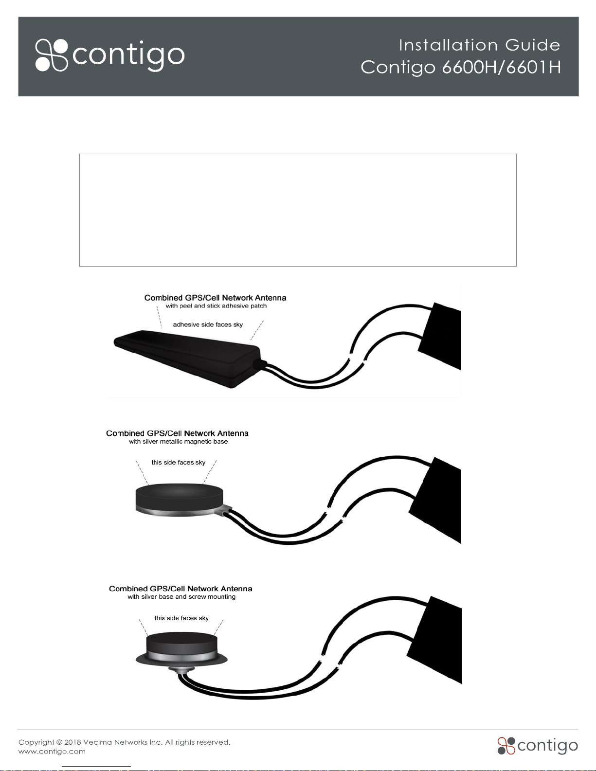
The following antenna models are supported for the 6600H:
Wedge Antenna – Part #: 655x-ANT-WEDGE
•
Black plastic housing; 5.4 in (138mm) length; 1.25 in (32mm) width;
0.44 in (11.2mm) depth;
•
Mounted with peel-and-stick adhesive patch.
Magnetic Weatherproof Antenna – Part #: 655x-ANT-WP-M
•
Black plastic with silver magnetic metal base; 2.54 in (64.5mm)
diameter; 0.54 in (13.6mm) depth;
•
Mounted on any exterior metal surface.
Drill-through Weatherproof Antenna – Part #: 655x-ANT-WP-DT
•
Black plastic with silver metal base and rubber weather-seal
gasket; 2.54 in (64.5mm) diameter; 0.77 in (19.5mm) depth
(excluding screw post);
• Screw post mount for drill-through applications.
For best performance, the top of the antenna should face the sky
through the area of least signal blockage.
• If the installation is not required to be covert, an ideal location is
underneath the front windshield glass. For covert installations, an
ideal location is under the dashboard, as close to the front
windshield as possible.
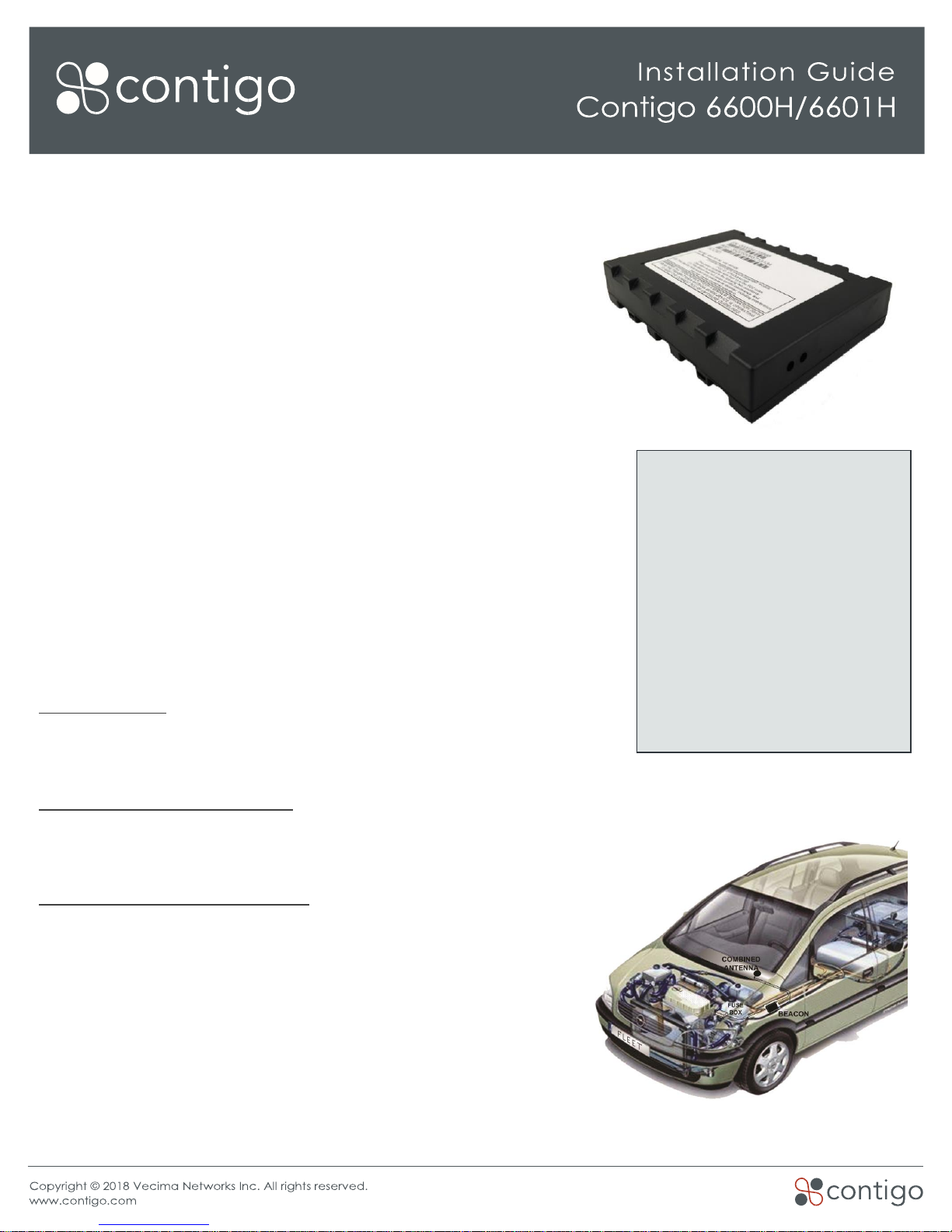
Contigo 6600H/6601H Beacon
Kit Contents
› GPS Beacon device with SIM
› Combined GPS/Cell Network
› antenna (if required)
› Wiring harness
Tools and Supplies Required
› Wire cutters, wire strippers
› Voltmeter (multimeter)
› Soldering iron, solder
› Electrical tape
› Plastic cable ties
› Screw drivers, mounting screws
› Wrenches, sockets
• In a car, the antenna can be mounted under the rear window or in the trunk, under the rear deck, as
close to the rear window as possible.
Antenna Installation Notes
• Signals will penetrate upholstery, carpet, plastic dashboards, etc., but not metal
panels or brackets.
• Signals will penetrate window glass but not metallic tinted windows or painted
edges of windows.
• Radio antenna or defrost wires embedded in glass may degrade signals.

Beacon Installation Position
• Determine beacon installation position but do not fasten it in place until all wiring is complete.
• Determine the best location for the beacon – a strong flat surface that can be drilled to accommodate
the mounting holes is ideal. Any spot where the beacon can be fastened in place with plastic cable ties
is suitable.
• For the 6600H with an external antenna, under a seat is often a suitable location for beacon installation.
Be sure it is not close to any heat sources or areas that experience moisture or vibration. The beacon is
not waterproof or weatherproof and should always be installed in the passenger compartment of the
vehicle.
• The 6601H has an internal antenna contained within the beacon housing. It is therefore important that the
top face of the beacon (the side with the large label) is facing the sky with no metallic obstruction. These
models are ideally located under the dashboard, and the same guidelines for installing an external
antenna (described above) are applicable.
• Visibility of the indicator LEDs will be useful for testing and troubleshooting.
Connect Power and Ignition Sense
The power harness included in the installation kit contains 14 wires, 3 of which are bundled together. The bundle
contains the 8-30V constant Power (Red), Ground (Black), and Ignition Sense (White) wires.
Notes
• Connect the wiring harness to the power and ignition source, as well as any I/O sources (if used), before
attaching the harness to the beacon.
• If wiring harness wires need to be extended, use the same gauge wire and solder the extension wire on,
then insulate with heat shrink tubing or electrical tape.
• Ensure that no wires are routed near heat sources.
Power Connection Instructions
• Connect the Black (Ground) wire to battery negative or the vehicle chassis – this wire MUST be connected
first, before the power or ignition sense wires. Be sure the grounding screw is not painted or coated with
an insulating material.
• With the vehicle’s ignition turned off, use a multimeter to assist in finding a suitable, constant 8-30V power
connection point – directly to the vehicle’s battery may be best. Important note: The red (power) cable
is configured with an in-line 3-amp fuse. This fuse must be installed as close as possible to the primary
power source connection.
• Ensure that any wires in the wiring harness that are not to be connected do not come in contact with
power, ground, or any other voltage. Insulate them with electrical tape.
 Loading...