

Page 1
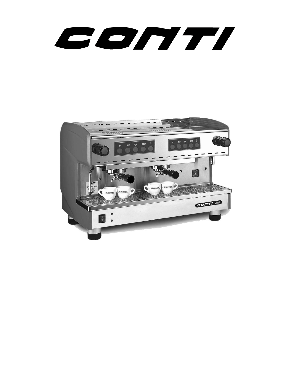
Club
NOTES TECHNIQUES
TECHNICAL DOCUMENT
Edition 12/00 - CONTICLUB
Tables des matières - NOTES TECHNIQUES
Index - TECHNICAL DOCUMENTS
SACOME, Document CONFIDENTIEL, Ne peut être reproduit ni communiqué sans notre accord préalable.
SACOME, CONFIDENTIAL Document, it is forbidden to duplicate or communicate this document without previous authorization.
Page 2

CONTICLUB
TABLE DES MATIERES INDEX
P
AGE DESIGNATION
1. TABLEAUX CARACTERISTIQUES
2. TABLEAUX CARACTERISTIQUES
3. GENERALITES ET ENCOMBREMENTS
4. INSTALLATION
5. MISE EN SERVICE
6. ELEMENTS D'UTILISATION
7. PROGRAMMATION DES DOSES
8. UTILISATION DES DOSES PROGRAMMEES
PREPARATION POUR FAIRE UN BON CAFE
9. ENTREE D'EAU
10. SCHEMA HYDRAULIQUE
11. REGLAGE PRESSION POMPE
12. ACCESSIBILITE REGLAGE POMPE
13. REGLAGE DU PRESSOSTAT
14. DEMONTAGE ET MONTAGE DE LA JOUE
15. DESIGNATION ELECTRIQUE
16. SCHEMA ELECTRIQUE
17. CONTICLUB AUTONOME
18. SCHEMA : CONTICLUB AUTONOME
19. ENTRETIEN PREVENTIF
20. ENTRETIEN PREVENTIF
DESIGNATION
MACHINE CHARACTERISTICS
MACHINE CHARACTERISTICS
FUNCTIONS AND DIMENSIONS
INSTALLATION
OPERATION
OPERATING INSTRUCTIONS
PROGRAMMING COFFEE MEASURES
USING THE PROGRAMMED MEASURES –
HOW TO MAKE THE PERFECT COFFEE
WATER INLET
HYDRAULIC DIAGRAM
ADJUSTING PUMP PRESSURE
ACCESS TO PUMP CONTROL
ADJUSTING PRESSURE SWITCH
REMOVING AND FITTING THE SIDE PANEL
FUNCTION DIAGRAM
ELECTRICAL DIAGRAM
FREE STANDING CONTICLUB
FREE STANDING CONTICLUB DIAGRAM
MAINTENANCE OF MACHINES
MAINTENANCE O
F MACHINES
Edition 12/00 - CONTICLUB
Tables des matières - NOTES TECHNIQUES
Index - TECHNICAL DOCUMENTS
SACOME, Document CONFIDENTIEL, Ne peut être reproduit ni communiqué sans notre accord préalable.
SACOME, CONFIDENTIAL Document, it is forbidden to duplicate or communicate this document without previous authorization.
Page 3

TABLEAUX CARACTERISTIQUES
ALIMENTATION
D’EAU
VIDANGE ELECTRICITE
220/240V - 50/60Hz
*Pression minimum 1,5 bar
*Sortie machine 3/8" mâle
*Prévoir la tuyauterie d’alim.
résistant à une pression minimum
de 10 bars
*TH=<7
*Sans pression
*Sortie machine embout
cannelé
*Assurer un raccordement qui
n’occasionne aucun risque de
retour
120V - 60Hz
pour 1G (UL)
uniquement
TYPE
MACHINE
PUISSANCE
CHAUFFAGE
PUISSANCE
INSTALLEE
INTENSITE
ABSORBEE
W W 110V 220V
1G (UL) 1350 1450 7
1G (UL) 1350 1450 12,5
2G (UL) 2400 2500 11,5
CAPACITE DE LA CHAUDIERE EN LITRES
1G 2G
TOTAL 8 12
VOLUME EAU CHAUDE 6 9
VOLUME VAPEUR 2 3
POIDS
(Kg)
POIDS EN
MARCHE (Kg)
1G 48 54
2G 61 70
Edition 12/00 - CONTICLUB
NOTES TECHNIQUES - TECHNICAL DOCUMENTS - page 1
SACOME, Document CONFIDENTIEL, Ne peut être reproduit ni communiqué sans notre accord préalable.
SACOME, CONFIDENTIAL Document, it is forbidden to duplicate or communicate this document without previous authorization.
Page 4
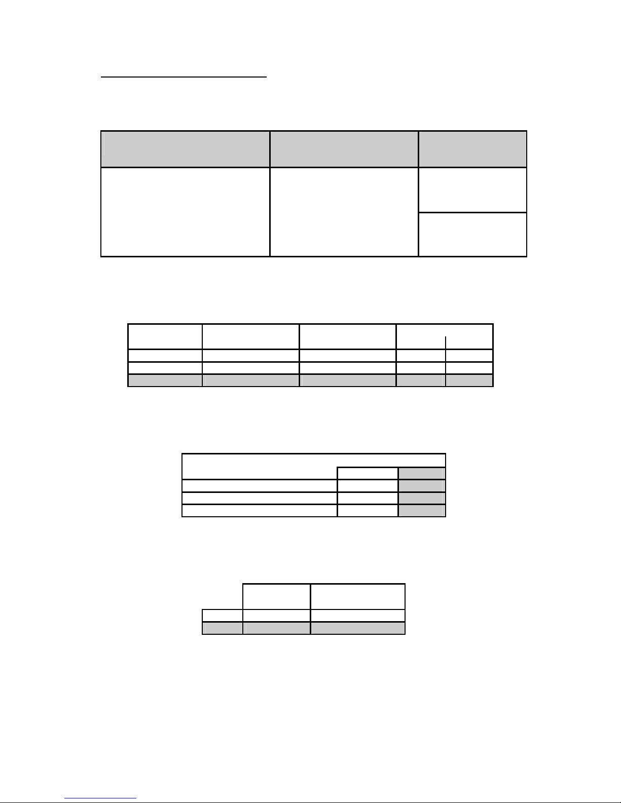
MACHINE CHARACTERISTICS
WATER SUPPLY DRAIN POWER
220/240V - 50/60Hz
*Minimum pressure 24 Psi
*3/8" male connector
*Water supply pipes resistant to
145 Psi
*TH=<7
*Without pressure
*Drain with a ribbed joining
piece
*ensure that water can not
return to the machine
120V - 60Hz
to 1G (UL)
only
TYPE HEATING INSTALLED POWER USED
MACHINE POWER W POWER W 110V 220V
1G (UL) 1350 1450 7
1G (UL) 1350 1450 12,5
2G (UL) 2400 2500 11,5
CAPACITY OF BOILER IN LITERS
1G 2G
TOTAL 8 12
VOLUME OF HOT WATER 6 9
VOLUME OF STEAM 2 3
WEIGHT
(Kg)
WEIGHT WHEN
WORKING (Kg)
1G 48 54
2G 61 70
Edition 12/00 - CONTICLUB
NOTES TECHNIQUES - TECHNICAL DOCUMENTS - page 2
SACOME, Document CONFIDENTIEL, Ne peut être reproduit ni communiqué sans notre accord préalable.
SACOME, CONFIDENTIAL Document, it is forbidden to duplicate or communicate this document without previous authorization.
Page 5
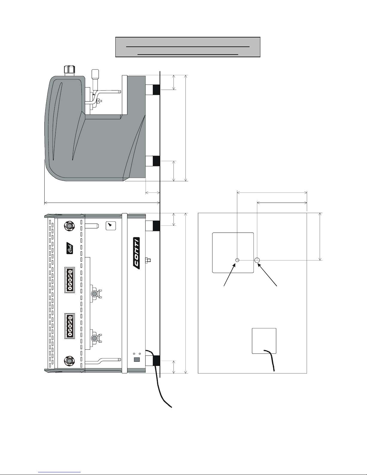
GENERALITES ET ENCOMBREMENTS
FUNCTIONS AND DIMENSION
S
515
95
65
1G=400 / 2G=745 485
80
55
55
210
300
210
Alimentation
Feeding
3/8"
Vidange
Drain
1/2"
Cable 3X2.5²
L=150cm
Edition 12/00 - CONTICLUB
NOTES TECHNIQUES - TECHNICAL DOCUMENTS - page 3
SACOME, Document CONFIDENTIEL, Ne peut être reproduit ni communiqué sans notre accord préalable.
SACOME, CONFIDENTIAL Document, it is forbidden to duplicate or communicate this document without previous authorization.
Page 6

INSTALLATION
Le branchement de la machine sur une
installation existante est normalement fait par
nos agents.
Il est recommandé d'utiliser un adoucisseur
d'eau, principalement quand l'eau alimentant la
machine présente une dureté supérieure à 7°TH,
et de procéder régulièrement à ses régénérations.
Il est indispensable de placer un robinet de
barrage d'eau, ainsi qu'une protection électrique
normalisée, adaptée à la tension et à la puissance
installée.
CET EQUIPEMENT DEVRA ETRE CONFORME
AUX NORMES EN VIGUEUR DANS LE PAYS OU
LA MACHINE EST INSTALLEE. IL EST A LA
CHARGE DU CLIENT.
En cas d'arrêt total de la machine, fermer le
robinet de barrage d'eau et interrompre
l'alimentation électrique.
NOTA:
UNE MACHINE SANS SURVEILLANCE DOIT
ETRE ISOLEE DE SES SOURCES
D'ALIMENTATION HYDRAULIQUE ET
ELECTRIQUE.
UNE PRISE DE TERRE EFFICACE, RELIEE A LA
BORNE PREVUE A CET EFFET SUR L'APPAREIL,
EST OBLIGATOIRE.
NE JAMAIS DEBRANCHER LA TERRE TANT QUE
L'ALIMENTATION ELECTRIQUE EST RELIEE A
LA MACHINE.
INSTALLATION
The installation of the machine to an existing
fitting is normally carried out by our agents. It is
recommended that a water softener is used,
especially if the water supplying the machine has
more than 7° total hardness. The softener must
be recharged at regular intervals.
In addition to the machines' tap valve, it is crucial
that a water cut-off valve be installed as well as a
standardised electrical circuit protection device
which must be in accordance with the voltage
and the installed power.
THESE DEVICES MUST CONFORM TO
DOMESTIC STANDARDS AND IS THE
RESPONSABILITY OF THE CUSTOMER.
When the machine is not in use, close the water
cut-off valve and cut the electrical power supply.
NOTE:
WHEN THE MACHINE IS NOT SUPERVISED IT
MUST BE DISCONNECTED FROM ITS
ELECTRICAL SOURCE AND ITS WATER SUPPLY.
IT IS FUNDAMENTAL THAT THE MACHINE IS
EARTHED BY THE TERMINAL PLUG.
NEVER DISCONNECT THE EARTH WIRE WHEN
THE MACHINE IS CONNECTED TO THE POWER
SUPPLY.
Edition 12/00 - CONTICLUB
NOTES TECHNIQUES - TECHNICAL DOCUMENTS - page 4
SACOME, Document CONFIDENTIEL, Ne peut être reproduit ni communiqué sans notre accord préalable.
SACOME, CONFIDENTIAL Document, it is forbidden to duplicate or communicate this document without previous authorization.
Page 7
MISE EN SERVICE
ALIMENTATION
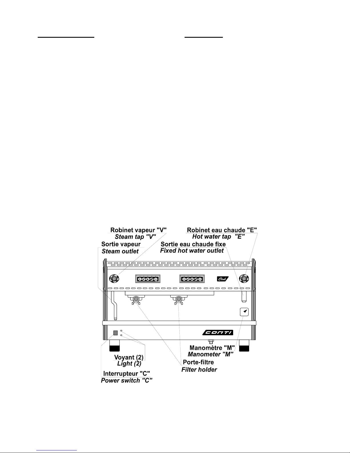
Ouvrir le robinet d'eau extérieur général si
nécessaire, puis ouvrir le robinet de barrage. Ne
pas mettre sous tension électrique.
A. PREMIER REMPLISSAGE EN EAU
-S'assurer que les robinets d'eau chaude "E" et
vapeur "V" sont fermés.
-Mettre l'interrupteur "C" sur 1 (alimentation
électrique de la machine), le voyant vert de mise
sous tension et le voyant rouge de défaut général
(manque d'eau ou surchauffe chaudière)
s'allument. La chaudière se remplit
automatiquement, la machine ne chauffe pas (le
contacteur général reste ouvert). Une fois l'eau
en contact avec la sonde de sécurité, la machine
se met en chauffe automatiquement et le voyant
rouge s'éteint (le contacteur général se ferme).
B. REMPLISSAGES SUIVANTS
-Le remplissage suivant se fera automatiquement
au fur et à mesure du prélèvement d'eau chaude
(sonde de niveau maxi).
OPERATION
WATER SUPPLY
If necessary, open the external water supply
valve and then the water cut-off valve. Ensure
power is off.
A. INITIAL FILLING
-Ensure that the hot water tap 'E' and steam tap
'V' are closed.
-Push switch 'C' to position 1 (power on) and the
red light (indicating a lack of water supply or
overheating of the boiler) and the green light for
indicates the machine is on will light up. The
boiler will fill automatically but will not heat the
water (the general circuit contactor is opened)
until the minimum level has been achieved. At
this point the green light will come on and the red
light will turn off (the general contactor is closed).
B. FURTHER FILLINGS
-The machine automatically ensures that it is
constantly maintained at the required level.
Edition 12/00 - CONTICLUB
NOTES TECHNIQUES - TECHNICAL DOCUMENTS - page 5
SACOME, Document CONFIDENTIEL, Ne peut être reproduit ni communiqué sans notre accord préalable.
SACOME, CONFIDENTIAL Document, it is forbidden to duplicate or communicate this document without previous authorization.
Page 8

PRESSION D'UTILISATION - MANOMETRE
La pression dans la chaudière est réglée pour
osciller entre 0,6 et 0,8 bar dans la zone verte du
manomètre.
Un régulateur automatique assure un maintien
constant de la pression et limite la dépense de
courant à son minimum.
Il est déconseillé de travailler avec une pression
en zone bleue ou rouge.
NOTA:
Un thermostat de surchauffe coupera le
chauffage de la chaudière, en cas d'augmentation
anormale de la température. Le voyant rouge
s'allume, la machine se met en sécurité.
LA MACHINE EST PRETE A FONCTIONNER.
ELEMENTS D'UTILISATION
PRISE VAPEUR
Un robinet "V" est prévu pour permettre le
chauffage des liquides par projection de vapeur.
Le liquide à réchauffer doit être placé de
préférence dans un récipient assez profond.
L'extrémité du diffuseur de vapeur doit tremper
dans le liquide mais sans toucher le fond du
récipient.
La vapeur peut être utilisée également pour la
stérilisation et le chambrage des verres.
PRISE D'EAU CHAUDE
Un robinet "E" est prévu pour permettre la
préparation d'infusions, grogs, etc. Ne pas ouvrir
le robinet brusquement, ceci à fin d'éviter les
projections d'eau sous pression et à haute
température.
FILTRES
La machine est livrée avec deux modèles de
filtres : une tasse et deux tasses; ne jamais faire
une tasse de café dans le filtre deux tasses.
Ceux-ci doivent être constamment débouchés et
très propres.
Pour vider les filtres du marc de café usé,
retourner le porte-filtre et frapper légèrement sur
le bord d'une boîte en bois; ne jamais frapper sur
du métal ou sur un corps dur.
PORTE-FILTRE
Ne jamais déclencher le porte-filtre pendant la
marche du groupe: l'arrêt du groupe est
contrôlable aux becs de sortie du café, ceux-ci ne
doivent plus éjecter de liquide.
Avoir soin de toujours laisser sur le groupe les
porte-filtres avec filtres remplis de marc du café
précédent, pour maintenir le porte-filtre à
température.
En cas d'arrêt prolongé, retirer le porte-filtre du
groupe (éjecter le marc usé restant dans le portefiltre).
BOILER PRESSURE - MANOMETER
The pressure in the boiler is regulated between
0,6 bars ( 10 PSI ) and 0,8 bars ( 12 PSI ), within
the green area on the manometer.
An automatic control unit ensures that a constant
pressure is maintained and keeps power
consumption as low as possible.
It is not recommended to work the machine in the
blue zone and if the indicator reaches the red
zone, turn the machine off immediately and call
the maintenance service.
NOTE:
The thermostat will cut the power to the boiler in
the case of abnormally high temperatures. The
red light will come on and the machine will stop
working.
THE MACHINE IS NOW READY TO OPERATE.
OPERATING INSTRUCTIONS
STEAM TAP
One tap, 'V', serves to heat liquid by injecting
steam.
The liquid to be heated should preferably be
placed in a deep container.
The tip of the steam outlet must be immersed in
the water but must not touch the bottom of the
container.
The steam may also be used to sterilize and warm
glasses.
HOT WATER TAP
Tap 'E' is provided for preparing tea, grog, etc. As
the water in this tap is under pressure and at a
high temperature, do not open it too quickly.
FILTERS
The machine is equipped with two types of filters;
one cup and two cups; never use a two cup filter
to make one cup of coffee. Always ensure that
the filters are unclogged and clean.
To remove used coffee grounds from the filter,
turn the filter holder upside-down and lightly tap
it on the edge of a wooden box; never strike it
against metal or other hard objects.
FILTER HOLDERS
Never release the filter holder whilst the unit is
operating; firstly, ensure that the liquid has
stopped flowing from the coffee spouts.
Always leave the filter-holder on the unit with the
filters filled with the grounds of the previous
coffee in order to maintain filter-holder
temperature.
When the machine is not in use for an extended
period of time, remove the filter holder and expel
the used coffee grounds.
Edition 12/00 - CONTICLUB
NOTES TECHNIQUES - TECHNICAL DOCUMENTS - page 6
SACOME, Document CONFIDENTIEL, Ne peut être reproduit ni communiqué sans notre accord préalable.
SACOME, CONFIDENTIAL Document, it is forbidden to duplicate or communicate this document without previous authorization.
Page 9
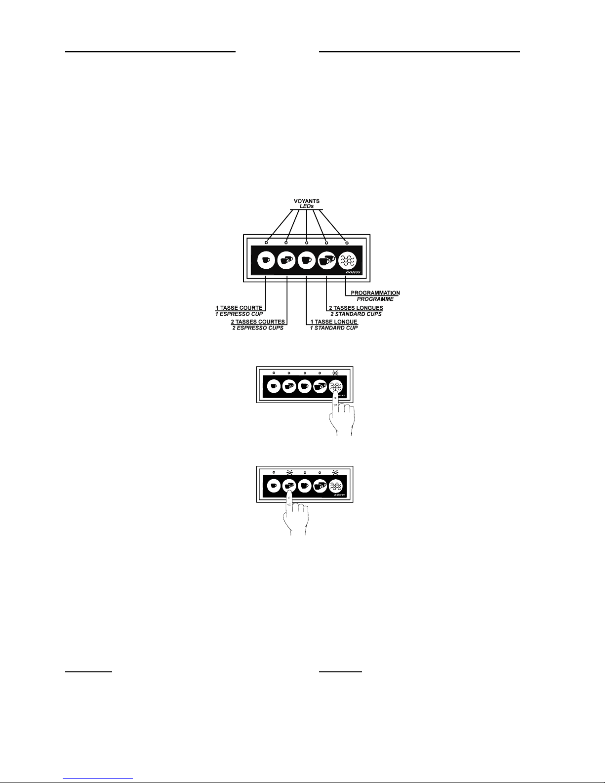
PROGRAMMATION DES DOSES
Pour avoir accès à la programmation des doses
volumétriques (turbines), il faut utiliser la dernière
touche à droite "P5" sur la plaque de commande.
Appuyer sur cette touche pendant 5 secondes (en
commençant à gauche du groupe); alors tous les
leds s'allument. Les opérations de
programmation doivent débuter dans un délai de
5 secondes après l'entrée en mode
programmation; sinon, on sort automatiquement
du mode programmation.
PROGRAMMING COFFEE MEASURES
In order to programm specific measures of coffee,
it is neccessary to use the last button on the right,
"P5", on the control panel.
Starting with the group on the left, keep button
"P5" depressed for 5 secondes until all the LEDs
light up on the display. Programming must begin
within 5 secondes after entering this mode,
otherwise, the machine will automatically return to
standby.
1. Appuyer sur la touche continue
et la maintenir enfoncée jusqu’à
ce que cette touche clignote.
2. Relâcher la touche continue.
Appuyer sur la touche dont
vous désirez régler le dosage.
Une fois le dosage désiré
atteint, effectuer une deuxième
pression sur cette touche.
Noter que le voyant de cette
touche reste allumé pendant la
procédure.
1. Push on the program button
and keep it pressed until it
blinks.
2. Release the program button.
Press the button for which you
want to modify the dosage.
When the dosage is acheived,
press the button a second time.
Note the light of this button, will
stay on during the procedure.
Pour programmer une autre touche, répéter la
procédure.
La programmation du 1
er
groupe est copiée sur le
second groupe, mais ce dernier peut être
programmé indépendamment.
NOTA
Il est prévu un délai maximum de 4 minutes pour
l'écoulement du café: ceci est important car sans
ce dispositif, le café coulerait à l'infini lorsque le
compteur volumétrique est en panne.
Attention :
Seules les 1TE et 2TE ont une pré infusion.
For programming another button, repeat the
procedure.
The programmation of the 1
st
group is copied on
the 2nd group, but the second one can be
programmed independanly.
NOTE:
Coffee will only flow for a maximum of 4 minutes:
this device is important as without it, the coffee
would flow continually if the measuring meter
were not to work.
Warning :
Only the 1 and 2 espresso cup pre-infusion
Edition 12/00 - CONTICLUB
NOTES TECHNIQUES - TECHNICAL DOCUMENTS - page 7
SACOME, Document CONFIDENTIEL, Ne peut être reproduit ni communiqué sans notre accord préalable.
SACOME, CONFIDENTIAL Document, it is forbidden to duplicate or communicate this document without previous authorization.
Page 10

UTILISATION DES DOSES PROGRAMMEES
Il suffit de sélectionner une des touches disponibles
pour les différentes doses et on obtiendra la dose
programmée. On peut arrêter le fonctionnement en
appuyant de nouveau sur la même touche. La dose
sélectionnée est signalée par le led respectif qui reste
allumé.
PREPARATION POUR FAIRE DU BON CAFE
L'obtention d'une bonne tasse de café est le résultat du
respect de certaines conditions: les 4 règles d'or du
parfait espresso. C'est à dire le MELANGE, le MOULINDOSEUR, la MACHINE, la MAIN.
Le mélange: le choix du type de café est très
important. On peut distinguer les qualités ARABICA
(donne un goût très parfumé, doux, chocolaté,
légèrement acide, avec une agréable pointe
d'amertume; couleur du café crème noisette) et
ROBUSTA (donne un goût moins parfumé, rude,
astringent et sensiblement plus amer; leur contenu de
caféine est environ le double; couleur du café brun
grisâtre). Le torréfacteur a une grande importance sur
la qualité même du café (choix des grains, procédés de
triage de ceux-ci, torréfaction, procédés d'emballage ).
Le moulin-doseur: le moulin et son réglage
sont essentiels.
Le moulin:
sa capacité de broyage des grains de café
doit être proportionnelle aux besoins de l'utilisateur.
En effet, l'utilisation excessive du moulin provoque
une surchauffe des meules et donc un déréglage
rapide du moulin.
Le réglage:
le réglage du moulin permet de choisir la
finesse de la mouture et la juste dose nécessaire pour
obtenir un café optimal. La dose doit être réglée à 7
grammes pour une tasse; la finesse doit permettre un
temps d'écoulement du café dans la tasse d'environ 20
- 25 secondes: ce délai garantit la diffusion de l'arôme
dans la tasse.
La machine doit être bien réglée (pression de
la pompe limitée à 9 bars, programmation des doses,
température de sortie de l'eau de la douchette
comprise entre 86 et 92 °C, ...) et bien entretenue par
un nettoyage quotidien.
La main, ou plutôt l'habileté de l'opérateur:
celui-ci doit bien sur maîtriser les trois facteurs
précédents, mais aussi:
savoir conserver le café: pour cela,
une confection de café ne doit pas rester à l'air libre. Il
faut savoir qu'un grain de café perd 1% de son arôme
par jour; le café moulu, lui en perd 45% par jour: on
évitera donc de moudre trop de café à la fois, ou de le
conserver dans des tiroirs...
le porte-filtre doit être chaud, donc il
doit être laissé sur le groupe. De même, le café doit
s'écouler dans des tasses chaudes: celles-ci seront
donc posées sur le chauffe-tasses.
USING THE PROGRAMMED MEASURES
Press one of the available buttons, and the
programmed amount of coffee will be obtained. The
flow can be stopped by repressing the same button.
The selected measure is indicated by the lit LED.
HOW TO MAKE THE PERFECT COFFEE
Obtaining a good cup of coffee is the result of a certain
number of factors. The four golden rules of a perfect
coffee: the MIX, the GRIND, the MACHINE and the
HAND.
The Mix: the choice of coffee is very
important; for example, it is easy to distinguish
between the quality of ARABICA ( a strong taste,
smooth, chocolaty, slightly acidic with a pleasant bitter
taste and a hazelnut cream colour ) and that of
ROBUSTA ( a weaker, harsh, bitter taste, double the
quality of caffine and a greyish brown colour).
Roasting also plays an important role in the quality of
each coffee ( choice of grains, selection procedure,
packaging procedure ).
The Grind: the grind and the control of the
grind are essential.
The coffee grinder: the coffee grinder should be
proportional in size to the requirements of the user.
The control: controlling the grind allows a choice in
the fineness of the coffee granules and in the correct
amount neccessary to make an ideal espresso; the
measure should be 7 grammes for one cup and the
fineness should allow for a flow time, for one cup, of
20-25 seconds - this allows time for the aroma to
transfer from the bean to the cup.
The Machine: the machine must be
controlled precisely ( with pump pressure regulated at
9 bars, pre-programmed measures and hot water
temperature between 86 and 92°c ), kept in good
working order and cleaned daily.
The Hand: as well as carrying out the three
golden rules above, the hand (better known as the
operator) needs to:
know how to store the coffee - taking
into account that it must stay in contact with the air for
as short a time as possible and that coffee looses 1%
of its' aroma each day ( ground coffee looses 45% per
day ); therefore storing or grinding too much coffee
must be avoided.
the filter holder must be kept warm
and always kept on the unit. In the same way, an
espresso should flow into a warmed cup taken directly
from the cup heater unit.
Edition 12/00 - CONTICLUB
NOTES TECHNIQUES - TECHNICAL DOCUMENTS - page 8
SACOME, Document CONFIDENTIEL, Ne peut être reproduit ni communiqué sans notre accord préalable.
SACOME, CONFIDENTIAL Document, it is forbidden to duplicate or communicate this document without previous authorization.
Page 11
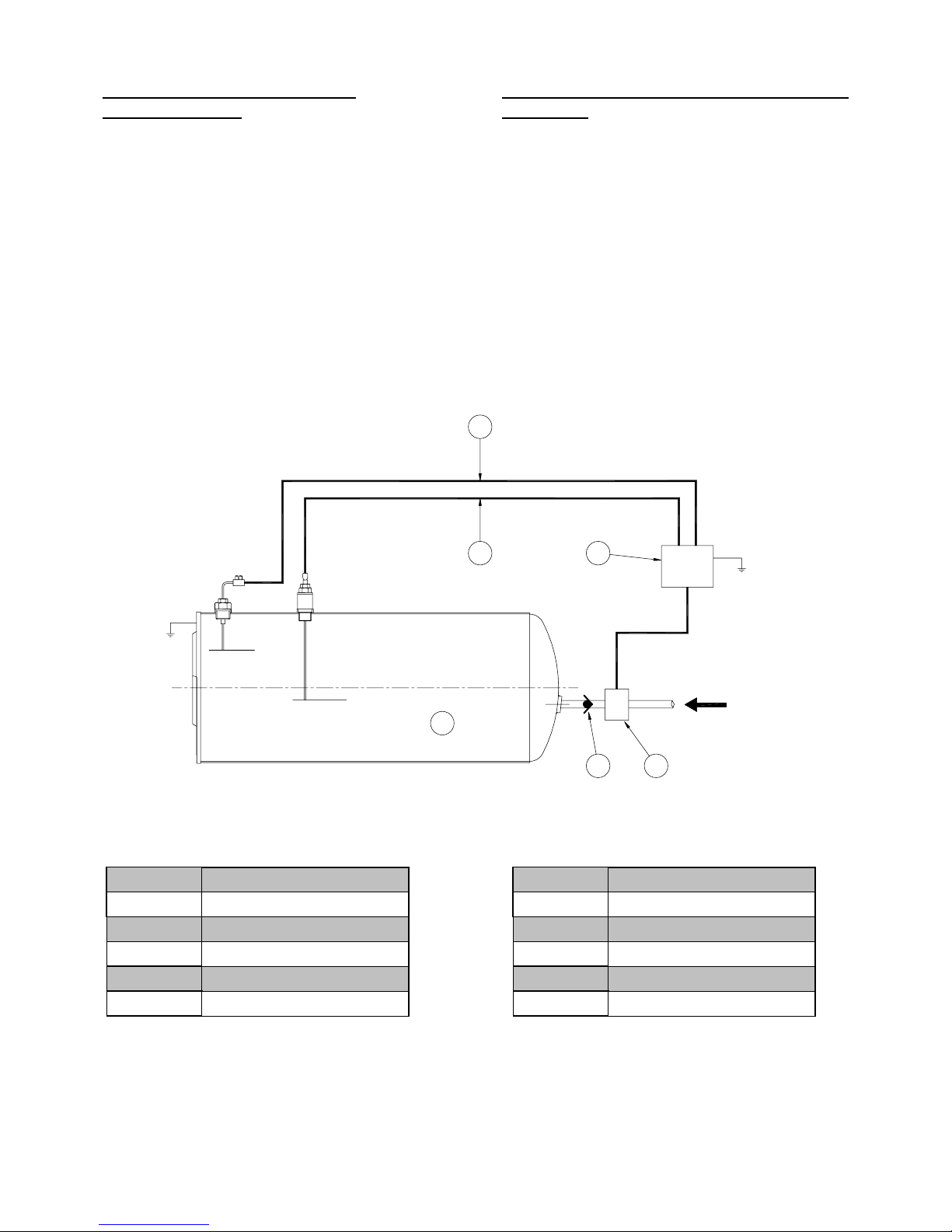
ENTREE D'EAU A DETECTION
ELECTRONIQUE
Lors du premier remplissage, une fois l'eau en
contact avec la sonde de sécurité (3), le
thermoplongeur se met en chauffe
automatiquement.
Si en cours d'utilisation le niveau d'eau de la
chaudière quitte l'extrémité de cette sonde (3), la
machine se met automatiquement hors tension.
Lorsque le niveau d'eau quitte l'extrémité de la
sonde de niveau (2), la centrale électronique (5)
actionne l'électrovanne d'entrée d'eau (4), qui
autorise le remplissage de la chaudière (1).
Un clapet anti-retour (6) empêche l'eau sous
pression de la chaudière, de retourner dans la
colonne d'alimentation, en cas de coupure d'eau.
WATER INLET AND ELECTRONIC LEVEL
CONTROL
For the initial filling of the boiler; as soon as the
water comes into contact with the safety sensor
(3), the immersion heater automatically heats up.
If, during use, the water falls below this level (3),
the machine automatically switches to standby
mode.
As soon as the water falls below the automatic
level sensor (2), the electronic controller (5)
commands the solenoid valve (4) to allow the
refill of the boiler (1).
A non-return valve (6), stops pressurized water
from returning up the water supply pipe, if the
water supply is cut off.
1
64
3
5
Eau
2
Edition 12/00 - CONTICLUB
NOTES TECHNIQUES - TECHNICAL DOCUMENTS - page 9
SACOME, Document CONFIDENTIEL, Ne peut être reproduit ni communiqué sans notre accord préalable.
SACOME, CONFIDENTIAL Document, it is forbidden to duplicate or communicate this document without previous authorization.
Page 12
FRANÇAIS
ENGLISH
FRANÇAIS
ENGLISH
1 Alimentation eau
Main water supply
17 Echangeur de chaleur
Heat exchanger
2 EV alimentation eau
Boiler solenoid valve
18 Chaudière eau/vapeur
Boiler
4 Anti-retour
Check valve
19 Thermoplongeur
Immersion heater
5 Robinet vapeur
Steam tap
20 Thermostat de
surchauffe
Overheating
thermostat
6 Sortie vapeur orient.
Steam wand
21 Cuvette de récup.
Drip tray
7 Manomètre chaudière
Boiler pressure gauge
22 Vidange cuv. récup.
Drip tray drain
8 Dépresseur
Pressure relief valve
23 Limiteur de pression
Pressure relief valve
9 Soupape de sureté
chaudière
Boiler safety valve
24 Filtre
Filter
10 Robinet eau chaude
Hot water tap
25 Pompe volumétrique
Pump
11 Brise jet eau chaude
Hot water spout
26 Clapet by-pass
By-pass valve
12 Corps de groupe café
Coffee unit body
27 Réglage de pression
pompe
Pump pressure
adjustment
13 Gicleur
Injector
28 Manomètre pompe
Pump pressure gauge
14 Porte-filtre
Filter holder
29 Prise de pression
pressostats
To pressure switch
15 Filtre + café moulu
Filter filled with
grounds
30 Volucompteur de
dosage
Flow meter
16 EV groupe café
Group solenoid valve
Maximum
Minimum
11
10
78
9
30
5
6
4
2
1
24
27
26
25
28
4
23
21 22
15
29
20
16
19
18
17
13
12
14
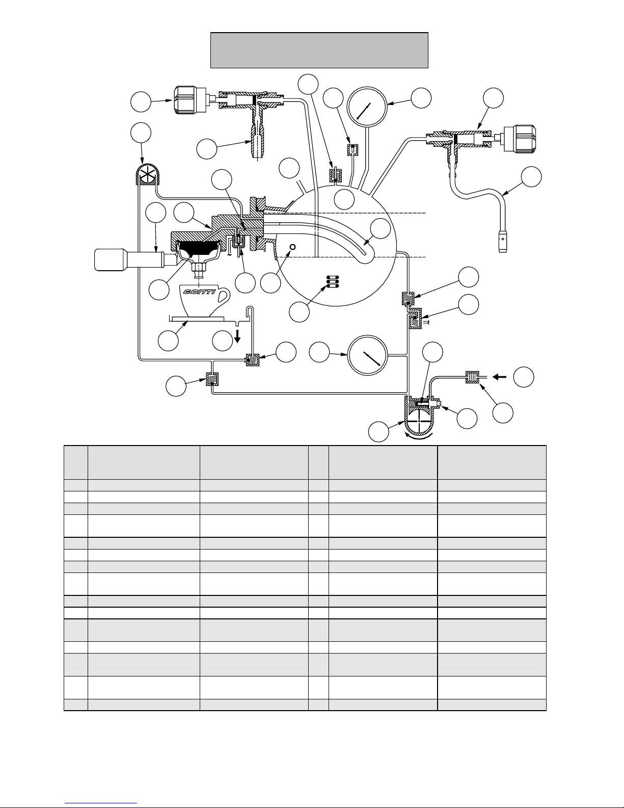
SCHEMA HYDRAULIQUE
HYDRAULIC DIAGRAM
Edition 12/00 - CONTICLUB
NOTES TECHNIQUES - TECHNICAL DOCUMENTS - page 10
SACOME, Document CONFIDENTIEL, Ne peut être reproduit ni communiqué sans notre accord préalable.
SACOME, CONFIDENTIAL Document, it is forbidden to duplicate or communicate this document without previous authorization.
Page 13
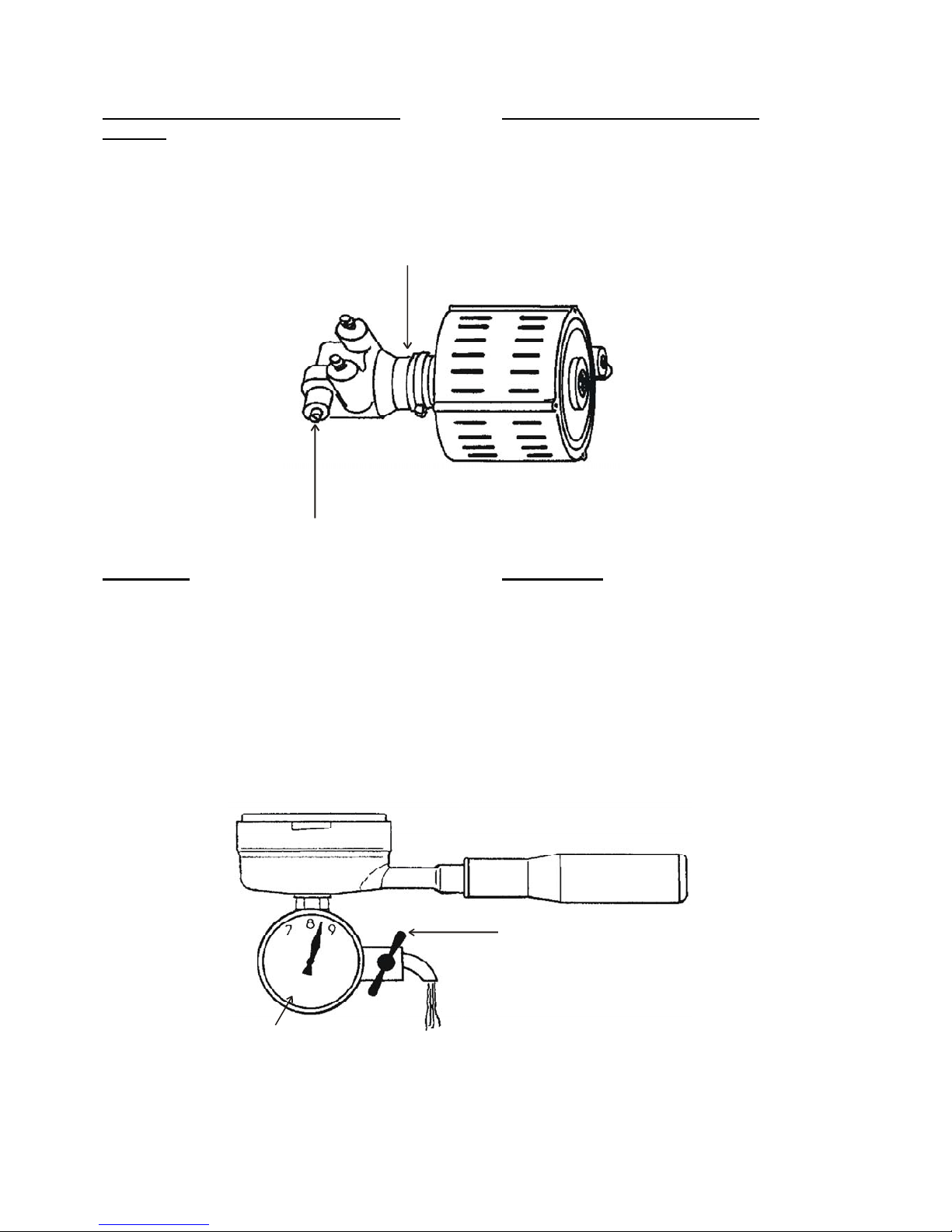
REGLAGE DE LA PRESSION DE LA
POMPE
La pompe est préréglée à la pression normale
de fonctionnement ; néanmoins si cela est
nécessaire le réglage peut être réajusté.
La vis de réglage "R" de la pompe "P" se trouve
au niveau inférieur du socle de la machine.
REGLAGE
Placer sur un groupe un porte-filtre (réf.327500)
avec un manomètre "M" gradué au moins
jusqu'à 12 bars et muni d'un robinet.
Faire fonctionner le groupe en faisant couler un
filet d'eau à l'aide du robinet, lire la pression.
Visser ou dévisser la vis de réglage "R" pour
augmenter ou diminuer la pression qui doit
s'établir entre 8 et 9 bars (maxi 9 bars).
Retirer le porte-filtre après arrêt du
fonctionnement du groupe.
ADJUSTING PUMP PRESSURE
The pump has been pre-regulated to normal
working pressure; however, if necessary it can
be readjusted.
The adjusting screw "R" on pump "P" is found
on the under side of the mounting plate.
P
R
ADJUSTING
Place a filter holder (ref.327500) with manometer
"M" onto a group - ensure the manometer is
calibrated up to at least 175 PSI (12 bars) and is
equipped with a tap.
Activate the machine, allowing a little water to
escape from the tap - read the pressure.
Tighten or loosen the adjustment screw "R" in
order to increase or decrease the pressure to
between 120 (8 bars) and 135 PSI (9 bars)
(maximum of 135 PSI - 9 bars).
Remove the filter holder once the dispensing
cycle has stopped.
ROBINET
(TAP)
M
Edition 12/00 - CONTICLUB
NOTES TECHNIQUES - TECHNICAL DOCUMENTS - page 11
SACOME, Document CONFIDENTIEL, Ne peut être reproduit ni communiqué sans notre accord préalable.
SACOME, CONFIDENTIAL Document, it is forbidden to duplicate or communicate this document without previous authorization.
Page 14
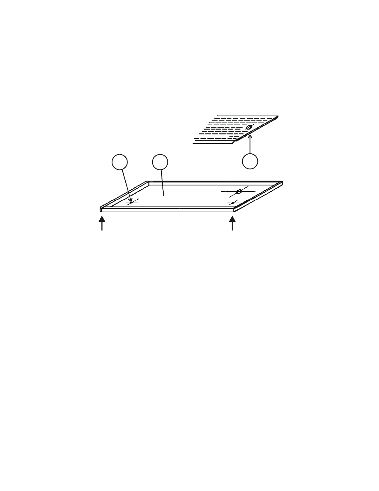
ACCESSIBILITE REGLAGE POMPE
Retirer l'égouttoir (1).
Pour ôter le bassin, soulever la partie inférieure
(AA') qui est clipsée, puis la tirer vers soi.
Attention : Ne pas dévisser les vis (2) situées
aux extrémités du bassin (3).
ACCESS TO PUMP CONTROL
Remove the drain (1).
To remove the basin, lift the front end (AA') and
pull it towards yourself.
Attention : Do not remove the screws (2) found
at each end of the basin (3).
2
1
3
A
A
'
Edition 12/00 - CONTICLUB
NOTES TECHNIQUES - TECHNICAL DOCUMENTS - page 12
SACOME, Document CONFIDENTIEL, Ne peut être reproduit ni communiqué sans notre accord préalable.
SACOME, CONFIDENTIAL Document, it is forbidden to duplicate or communicate this document without previous authorization.
Page 15
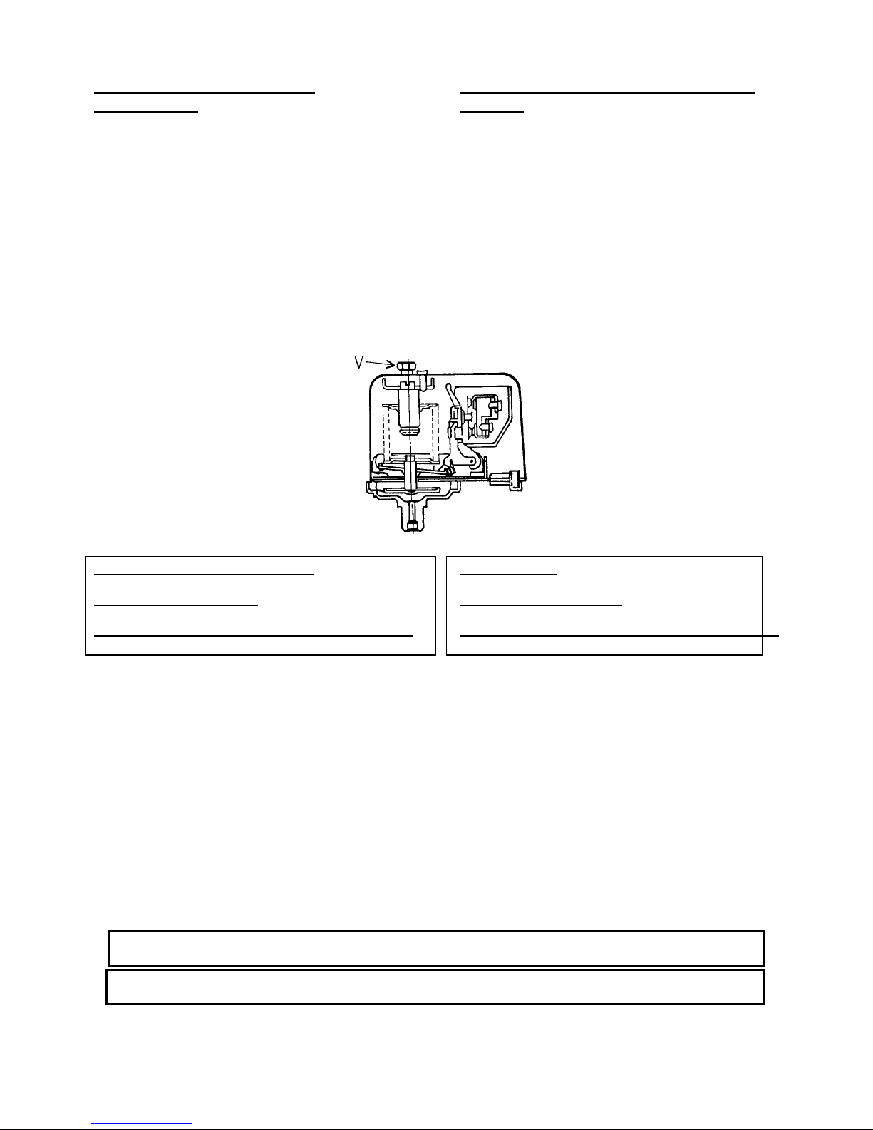
REGLAGE DU PRESSOSTAT
ELECTRIQUE
Le pressostat fonctionne entre deux valeurs de
pression qui correspondent respectivement à la
pression minimum de fermeture du circuit
électrique "P1" et à la pression maximum de
l'ouverture du circuit "P2". P2=P1+dP. (dP
représente la valeur de la pression différentielle
de l'appareil).
Le réglage de "P1" se fait en tournant la vis "V"
dans le sens horaire pour diminuer la pression et
dans le sens inverse pour l'augmenter.
Le réglage de la pression maxi "P2" se fait
automatiquement par l'intermédiaire du
différentiel "dP".
ADJUSTING ELECTRONIC PRESSURE
SWITCH
The pressure switch operates between two limit
pressure valves that correspond respectively to
the minimum closing pressure of the electrical
circuit "P1" and the maximum opening pressure
"P2". P2=P1+dP ( dP being the devices'
differential pressure valve).
"P1" is adjusted by turning screw "V" clockwise
to reduce pressure and anti-clockwise to increase
pressure. The maximum pressure "P2" is
adjusted automatically according to the
differential pressure "dP".
VALEUR DU REGLAGE EN USINE: P1=0,6 BAR.
P2=0,8 BAR.
CAPACITE ELECTRIQUE: 15A/250V ALTERNATIF
TEMPERATURE MAXIMUM DU FLUIDE MOTEUR:
140°C
ADJUSTMENT:
P1=0,6BAR ( 10 PSI )
P2=0,8BAR ( 12 PSI )
ELECTRICAL CAPACITY: 7KW/220V AC
12KW/380V AC
MAXIMUM TEMPERATURE OF MOTOR FLUID:
140°C/284°F
RECOMMANDATION
Avant toute intervention sur les divers organes
de la machine, il faut:
-Mettre l'interrupteur "C" sur 0;
-Couper l'eau (au robinet de barrage) et
l'électricité (à la protection normalisée);
-Annuler la pression dans la chaudière:
ouvrir le robinet vapeur "V", jusqu'à
l'absence de pression.
Si le retrait de la prise de terre est nécessaire, ne
le faire qu'après avoir déconnecté l'alimentation
électrique.
RECOMMENDATION
Before servicing the machine:
-Turn switch "C" to 0 (OFF);
-Shut off water supply ( at the water cut-off
valve ) and electricity supply ( at the circuit
protection device ).
-Lower the boiler pressure by opening the
steam tap "V".
Before removing the electrical earthing
connection, ensure that the mains supply is
disconnected.
LE NON-RESPECT DE CES DIRECTIVES DEGAGE LE CONSTRUCTEUR ET L'INSTALLATEUR DE
TOUTE RESPONSABILITE EN CAS D'ACCIDENT QUELCONQUE.
FAILURE TO COMPLY WITH THESE INSTRUCTIONS RELIEVES THE MANUFACTURER AND
THE INSTALLER OF ANY LIABILITY IN THE UNLIKELY EVENT OF AN ACCIDENT.
Edition 12/00 - CONTICLUB
NOTES TECHNIQUES - TECHNICAL DOCUMENTS - page 13
SACOME, Document CONFIDENTIEL, Ne peut être reproduit ni communiqué sans notre accord préalable.
SACOME, CONFIDENTIAL Document, it is forbidden to duplicate or communicate this document without previous authorization.
Page 16

DEMONTAGE DE LA JOUE
Retirer le chauffe-tasses en dévissant les deux
vis cylindriques fendues puis en le tirant de
quelques millimètres vers soi et enfin en le
soulevant délicatement (pour ne pas détériorer
les joues).
Retirer l'égouttoir et ôter le bassin comme
indiqué page précédente.
Décrocher la partie supérieure sans tirer
violemment sur la joue des éléments de tôlerie
Prendre la partie inférieure côté bassin et façade
arrière. Décrocher la partie opposée, côté
façade avant, avec prudence. Puis une fois cette
partie décrochée, tirer l'ensemble vers soi
délicatement.
REMONTAGE DE LA JOUE
Pointer le bas de la joue contre le châssis.
Enclencher la partie inférieure côté façade
avant, puis côté façade arrière, en laissant la
joue inclinée.
Tout en remontant la joue, faire entrer la façade
arrière dans son logement, puis la façade avant
ceci simultanément.
Terminer l'enclenchement de la façade avant
jusqu'à la partie supérieure arrondie. Avec la
paume de la main, tapoter sur la joue pour bien
l'enclencher.
REMOVING THE SIDE PANEL
Remove the cup heater, by unscrewing the two
split screws, and gently lifting it towards
yourself.
Remove the drainer and take away the basin as
shown in the following page.
Gently pull the upper part of the side panel.
Taking hold of the base of the panel, carefully
pull it away at the front. Once this part is
dislodged, carefully pull the whole panel
towards you.
REFITTING THE SIDE PANEL
Place the base of the panel against the frame.
Lock the lower back side of the panel into
position, then the front side, leaving the panel
slightly inclined.
Push the front of the panel into its place,
followed by the upper back side.
To finish the refitting of the panel gently lock the
upper section into place with the palm of your
hand.
Edition 12/00 - CONTICLUB
NOTES TECHNIQUES - TECHNICAL DOCUMENTS - page 14
SACOME, Document CONFIDENTIEL, Ne peut être reproduit ni communiqué sans notre accord préalable.
SACOME, CONFIDENTIAL Document, it is forbidden to duplicate or communicate this document without previous authorization.
Page 17
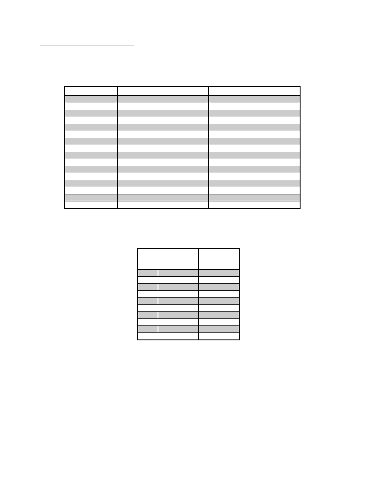
DESIGNATION ELECTRIQUE
FUNCTION DIAGRAM
REFERENCES DESIGNATIONS FUNCTION
C Contacteur
Contactor
CE Carte électronique
Main electronic controller
CN Connecteur tableau
Panels connector
CV Compteur volumétrique
Flow meter
EE EV entrée eau
Solenoid valve water feeding
EVG EV de groupe
Group solenoid valve
MP Motopompe
Motor/pump
P Pressostat 0,6/0,8 Bar
Pressure switch 0,6/0,8 Bar
RC Résistance chauffage
Immersion heater
RS Relais de sécurité
Safety relay
SN Sonde de niveau
Level sensor
SS Sonde de sécurité
Safety sensor
ST Sonde thermique
Thermic sensor
TS Thermostat de surchauffe
Overheating thermostat
VR Voyant rouge
Red light
VV Voyant vert
Green light
CODE
COULEUR
FILS
CABLE
COLOUR
CODE
1 marron
Brown
2 rouge
Red
3 orange
orange
4 jaune
Yellow
5 vert
Green
6 bleu
Blue
7 violet
violet
8 gris
Grey
9 blanc
White
0 noir
black
Edition 12/00 - CONTICLUB
NOTES TECHNIQUES - TECHNICAL DOCUMENTS - page 15
SACOME, Document CONFIDENTIEL, Ne peut être reproduit ni communiqué sans notre accord préalable.
SACOME, CONFIDENTIAL Document, it is forbidden to duplicate or communicate this document without previous authorization.
Page 18
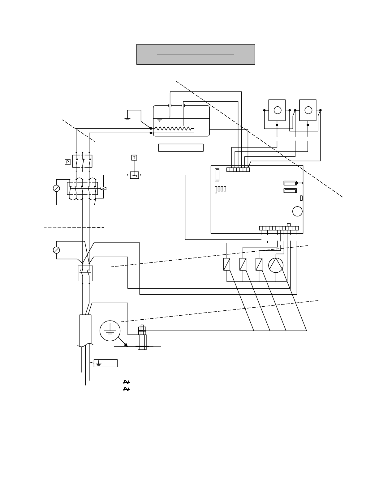
SCHEMA ELECTRIQUE
ELECTRONIC DIAGRA
M
K
CE
06
3,15A
12
P1
892911
04
CN 2
1
P5
CN 1
1
P
3
P
2
C
N
7
P
4
7
OUTOUT
-++
CV2
-
CV1
E
E
E
V
G
2
E
V
G
1
M
P
TS 140°C
P 0. 6/ 0.8 B
RC
SN
SS
1G=1350W / 2G=2400W
05
26
62
6
12
Ros e
Ros e
92 917
Ph
Terre
C
VV
VR
45
2.5mm²
2.5mm²
0.5mm²
0.5mm²
0.5mm²
ST
N
22 0/ 24 0
10 0/ 12 0
Edition 12/00 - CONTICLUB
NOTES TECHNIQUES - TECHNICAL DOCUMENTS - page 16
SACOME, Document CONFIDENTIEL, Ne peut être reproduit ni communiqué sans notre accord préalable.
SACOME, CONFIDENTIAL Document, it is forbidden to duplicate or communicate this document without previous authorization.
Page 19

OPTION : CONTICLUB AUTONOME
AVERTISSEMENT :
• La CONTICLUB peut être transformée pour
une utilisation autonome, c'est à dire pour être
installée sans une alimentation d'eau
extérieure ni une prise de vidange extérieure.
• Pour cela il faut monter le kit d’adaptation
référence 410014
• Le montage de ce kit peut être réalisé soit par
le concessionnaire ou agent, soit directement
à l’usine.
INSTALLATION :
Vous avez le choix d'installer la machine soit
comme indiqué dans la première solution (bacs
en dessous de la planche de travail), soit comme
indiqué dans la seconde solution (bacs
directement sous la machine).
Les bacs ne sont pas fournis : il vous suffit
d'installer des bacs du commerce suivant la
solution retenue, genre bacs ménagers. La
solution avec les bacs sous la planche de travail
permet d'installer des bacs plus volumineux afin
d'éviter des remplissages trop fréquents.
MISE EN ROUTE :
• installer la machine sur la planche de travail
• mettre en place les 2 bacs suivant la solution
retenue
• remplir le bac destiné à l'alimentation, et
plonger les flexibles après les avoir monté
comme indiqué sur le plan ci-après.
• mettre le pont P4 dans la centrale électrique
(voir schéma).
• brancher la machine, appuyer sur
l'interrupteur ON
• à la première mise en route la chaudière se
remplit
• la chaudière étant remplie, la pompe s'arrête,
faites l'appoint d'eau du bac d'alimentation
• la machine est prête
.
• pour le reste de son fonctionnement,
consulter la notice standard de mise en route.
RECOMMANDATIONS :
• nettoyer régulièrement les bacs (une fois par
jour recommandé)
• quand l'eau ne coule pas dans la tasse, en
demandant 1 ou 2 cafés, ou quand le voyant
rouge s'allume, contrôler le niveau d'eau dans
le bac d'alimentation et procéder à l'appoint
d'eau nécessaire.
OPTION : FREE STANDING CONTICLUB
IMPORTANT NOTES
•
The CONTICLUB can be modified into a free-
standing version external water supply, or
connection to the drain.
•
For this modification, you need to mount the
adaptation kit ref.410014
•
The mounting of the kit can be done, xether by
the distributor, or in our factory before
shipmet (price is different).
INSTALLATION :
The XEOS Solo could be either installed as
described in "solution 1" (water container under
the work top) or "solution 2" (container under the
machine).
The containers are not supplied : any sort of
household equipment is suitable. Solution 1
allows to use any sized containers.
HOW TO OPERATE :
•
set the machine on the work top.
•
set the two containers according to the opted
solution.
•
fill up the water container, immerse the hoses
assembled as is recommended on the diagram
below.
•
Put the bridge circuit P4 inside the electronic
controler (see diagram).
•
connect the machine and switch ON.
•
the boiler fills up automatically.
•
when the boiler is full, the pump stops, and
the container, if less then 5 liters, has to be
refilled.
•
the machine is now ready to operate
•
for further details on the functioning, refer to
the installation manual.
RECOMMMANDATIONS :
•
clean both containers on a regular basis,
preferably every day.
•
If coffee is not dispensed or when red light is
on, check the water supply level and add the
necessary volume of water.
Edition 12/00 - CONTICLUB
NOTES TECHNIQUES - TECHNICAL DOCUMENTS - page 17
SACOME, Document CONFIDENTIEL, Ne peut être reproduit ni communiqué sans notre accord préalable.
SACOME, CONFIDENTIAL Document, it is forbidden to duplicate or communicate this document without previous authorization.
Page 20
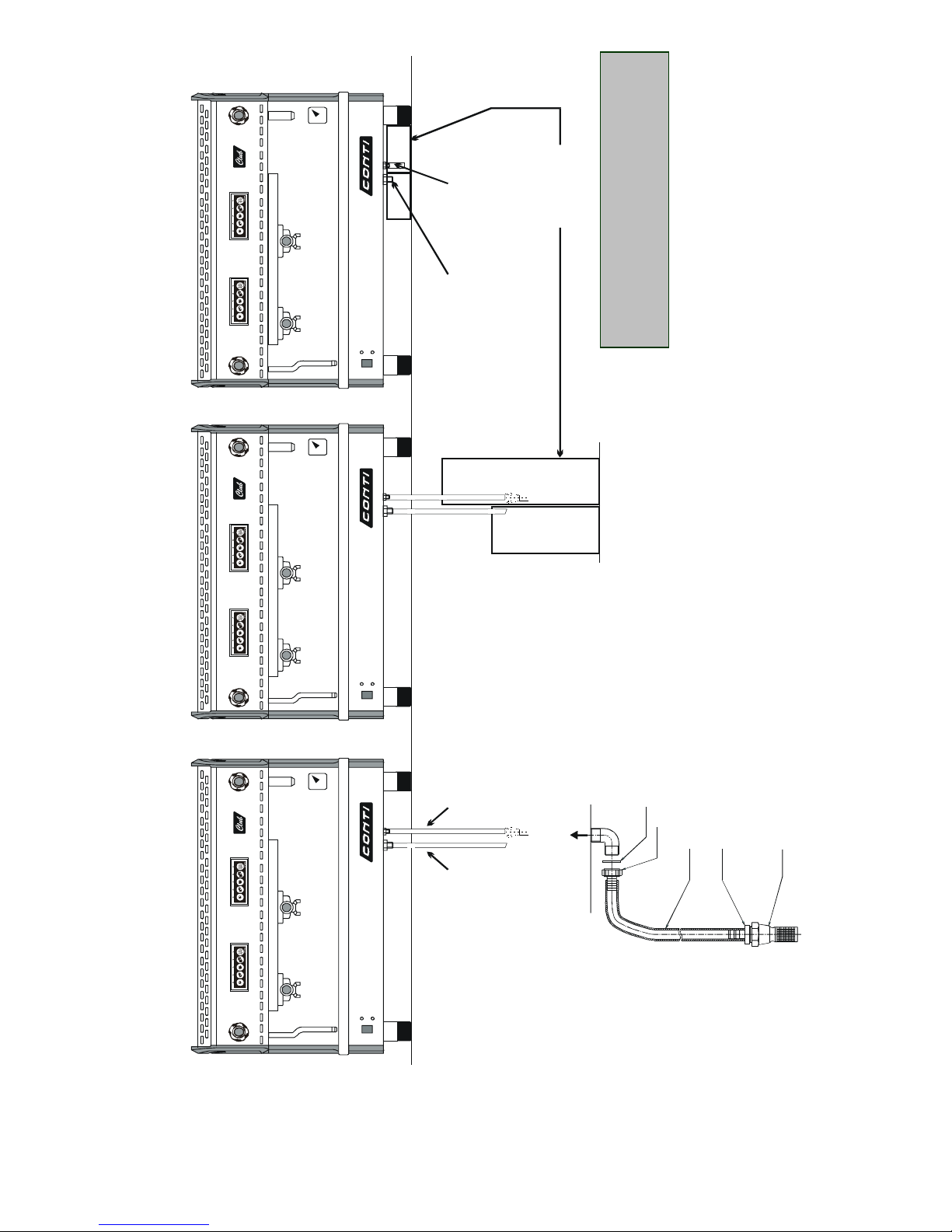
409630
409700
464419
403071
409195
Alimentation 3/8"
Lg= 1200
Alimentation
Feeding
3/8"
Vid an g e
Drain
1/2"
Lg = 1 2 0 0
Fle xi b l e s
de lo ngueur
maxima le 1200mm
Ho se s
(ma xim um
length 12000mm)
Flexible à couper
en fonction du bac
Hose (cut to fit
the container)
Ne pas racc order
de flexible
No hose
Bac s non fournis
C
o
n
t
a
i
n
e
r
s
n
o
t
s
u
p
p
l
i
e
d
1ère solution
Solution 1
2ème solution
Solution 2
CONTICLUB AUTONOME
FREE STANDING CONTICLUB
Edition 12/00 - CONTICLUB
NOTES TECHNIQUES - TECHNICAL DOCUMENTS - page 18
SACOME, Document CONFIDENTIEL, Ne peut être reproduit ni communiqué sans notre accord préalable.
SACOME, CONFIDENTIAL Document, it is forbidden to duplicate or communicate this document without previous authorization.
Page 21

ENTRETIEN PREVENTIF DES MACHINES
ENTRETIEN JOURNALIER
- Retirer les porte-filtres des unités à injection
et nettoyer le joint de porte-filtre avec la
brosse.
- Nettoyer la sortie eau chaude avec une
éponge à récurer.
- Nettoyer la sortie vapeur avec une éponge à
récurer; pour maintenir les trous du diffuseur
débouchés, utiliser une épingle puis purger
en ouvrant quelques secondes le robinet.
- Nettoyer la grille égouttoir et éponger la
cuvette.
ENTRETIEN HEBDOMADAIRE
- Nettoyer la douchette avec le filtre borgne
(pour chaque groupe): insérer ce filtre dans
un porte-filtre; enclencher celui-ci sur le
groupe; appuyer sur la touche deux tasses
longues; attendre quelques secondes puis ré
appuyer sur cette touche; rincer le filtre
borgne et répéter ces opérations 3 fois pour
chaque groupe.
- Brosser les porte-filtres dans l'eau
additionnée de lessive de façon à déboucher
les trous (ne jamais utiliser une aiguilles ou
une flamme).
MAINTENANCE OF MACHINES
DAILY MAINTENANCE
- Remove filter holders and clean with a brush.
- Clean the hot water outlet with a scouring
pad.
- Clean the steam outlet with a scouring pad;
in order to keep the nozzle unblocked, use a
needle or pin and open the steam tap a few
seconds to flush it clean.
- Clean the drain grating and basin.
WEEKLY MAINTENANCE
- Clean the sprinkler with the dummy filter ( for
each group ): insert the dummy filter in a
filter holder, lock it into position and press
the 2 large cups. Wait a few seconds, then
press the button once more; rinse the
dummy filter and repeat this action 3 times
for each group.
- Wash the filter holders in water in order to
unblock the holes ( never use a pin or a
flame to unblock them ).
Edition 12/00 - CONTICLUB
NOTES TECHNIQUES - TECHNICAL DOCUMENTS - page 19
SACOME, Document CONFIDENTIEL, Ne peut être reproduit ni communiqué sans notre accord préalable.
SACOME, CONFIDENTIAL Document, it is forbidden to duplicate or communicate this document without previous authorization.
Page 22
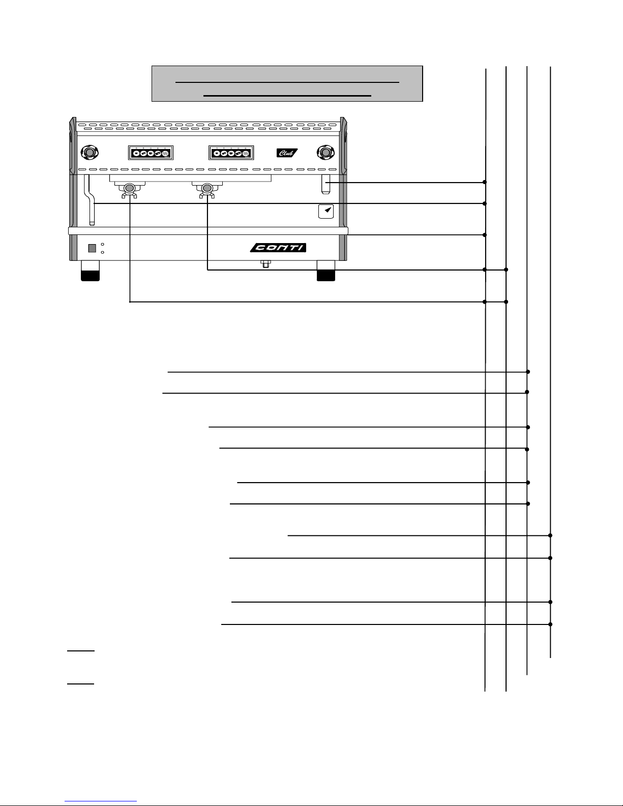
1-
1-
1-
1-
1-
1- Voir notice de mise en route
See installation manual
2- Vérifier sondes
Nettoyer le tartre si nécessaire
Check sensor
If necessary remove scale
3- Vérifier filtre arrivée eau
Nettoyer si nécessaire
Check the water inlet filter
Clean if necessary
4- Vérifier filtre et gicleur groupe
Nettoyer si nécessaire
Check filter and spray nozzle
Change if necessary
5- Vérifier sièges électrovannes de groupes
Nettoyer ou changer si nécessaire
Check solenoid connections
Clean or change as necessary
6- Vérifier joint soupape et dépresseur
Changer si nécessaire
Check valve seal and pressure relief valve
Change if necessary
NOTA
: Cet entretien préventif ne tient pas compte d'une mauvaise
régénération de l'adoucisseur - CONTI décline toute responsabilité
dans ce cas.
NOTE : The regeneration of the water softener is the responsability of
the client - CONTI takes no responsability for faults if this iis not
carried out.
Journalier
Hebdomadaire
Semestriel
Annuel
Daily Weekly Twice a yea
r
Y
earl
y
ENTRETIEN PREVENTIF DES MACHINES
MAINTENANCE OF MACHINES
Edition 12/00 - CONTICLUB
NOTES TECHNIQUES - TECHNICAL DOCUMENTS - page 20
SACOME, Document CONFIDENTIEL, Ne peut être reproduit ni communiqué sans notre accord préalable.
SACOME, CONFIDENTIAL Document, it is forbidden to duplicate or communicate this document without previous authorization.
 Loading...