

Contherm MITRE 4150, MITRE 4000 SERIES, MITRE 4200, MITRE 4400 Service Manual
Scientific Ltd
SERVICE MANUAL
MITRE 4000 SERIES
Sterilising - Standard/Tropicool/Cooled Models
CO2CELL CULTURE INCUBATORS
CONTHERM SCIENTIFIC LIMITED
P O BOX 30-605 LOWER HUTT 5040
TEL: (0064-4) 568 8034
FAX: (0064-4) 568 8095
EMAIL: contherm@xtra.co.nz

WARRANTY STATEMENT
* * * * * * *
CONTHERM Scientific Company will guarantee CONTHERM equipment for
a period of twelve months from the date of installation against faulty
workmanship and fabricated materials. This guarantee covers the
replacement of component parts found to be defective and authorised
labour charges during this period.
Should a malfunction occur or condition develop beyond reasonable
acceptance the company will accept responsibility for returning the unit to
its factory specification at no cost to the Purchaser providing that the
operating instructions have been observed and the defect is due solely to
faulty design, material and workmanship. That the defective part be
returned, freight paid to the nearest sales service office. Units outside the
warranty period will be accepted and repairs will be covered under an
extension of the above for 90 days.
In remote installations where it is not possible for the company's or
agents' engineers to attend, authority may be given to allow the Purchaser
to arrange such service.
The Purchaser is required to remit the purchase price of the unit to the
supplier within the terms of that supplier's condition of sale. CONTHERM
Scientific Company will accept no liability or shall its agents for
consequent damage of any kind due to a malfunction or component
failure.
* * * * * * *
MANUALP/4000_SERVICE_0712 July2012
4
STATEMENT of CONFORMITY
This CONTHERM cabinet conforms to the following standards:
• Electrical Safety: Designed to NZS6200 / AS3100:1994
• EMC: Complies with AS/NZS 2064: 1997
MANUALP/4000_SERVICE_0712 July2012
5
CONTENTS
SECTION 1 Definition of Terms
SECTION 2 Introduction and Specifications
SECTION 3 Installation
SECTION 4 Operating Instructions
SECTION 5 Calibration
SECTION 6 Theory of Operation
SECTION 7 Customer Troubleshooting and Maintenance
SECTION 8 Spare Parts Lists
SECTION 9 Fault / Alarm Codes
SECTION 10 Servicing / Replacing Parts
IMPORTANT All electrical servicing must be carried out by
suitably qualified personnel only.

MANUALP/4000_SERVICE_0712 July2012
6
SECTION 1 DEFINITION OF TERMS
For the purpose of our standard specifications the following definitions shall
apply:
a) WORKING SPACE
That portion of the internal space which is above the lowest shelf and
not less than 5cm from any wall (including roof).
b) CHAMBER TEMPERATURE
That temperature at the centre of the working space.
c) SPATIAL VARIATION
The difference between the midrange of all measured temperatures
obtained at one site and that at another site for those sites which give the
greatest difference.
d) TEMPORAL VARIATION
The maximum value of the temperature range obtained for the standard
site with the greatest range throughout the test interval.
e) TEMPERATURE OVERSHOOT
Any excess of actual over desired chamber temperature during a
heating up period.
f) TEMPERATURE REPRODUCIBILITY
Temperature regained without alteration to controls.
g) TEST INTERVAL
Interval of time to which the steady state characteristics apply (Max 1
hour).
NB: All the above apply with an empty chamber.
For definitions and test methods refer: AS2853 : 1986 (and Appendices)
MANUALP/4000_SERVICE_0712 July2012
7
SECTION 2 INTRODUCTION AND SPECIFICATIONS
The CONTHERM CAT4000 Mitre Series of Co2 Culture Incubators has been
expressly designed to give the widest choice of operating conditions consistent
with high reliability and low cost, the addition of microprocessor control gives
additional versatility and resolution while improving the degree of temperature
control. These Incubators are fitted with a UVC (254nm) SERILISING UV lamp.
All specifications are quoted for an enclosure temperature of +37oC with an
ambient Temperature of +20oC for Standard and Tropicool cabinets and for an
enclosure temperature of +20oC for cooled cabinets.
• Construction - Combination of High quality stainless steel and zinc plated
mild steel; epoxy coated exterior, full fibreglass insulation, High quality
stainless steel interior with full access door and magnetic door catch
• Safety - Fitted with an independent factory set Hi-Limit and user adjustable
Hi-Limit completely separate from normal controls.
• Convection - All units come with mechanical convection fan systems.
• Electrical - Designed to NZS6200 / AS3100:1994 240V AC M.E.N
• EMC - Complies with AS/NZS 2064: 1997
• All performances quoted at 20
o
C, ZP22 Microprocessor control System.
PERFORMANCE:
a) Temperature:
Nominal Range: Standard (Ambient +5oC) to +50oC
Tropicool (Ambient -5oC) to +50oC
*Cooled +15oC to +50oC
Temporal Variation Standard +_ 0.2oC
(Tropicool) +_ 0.3oC
(Cooled) +_ 0.4oC
Spatial Variation Standard +_ 0.4oC
(Tropicool) +_ 0.4oC
(Cooled) +_ 1.5oC
Initial Overshoot +2.0oC
Reproducibility +_0.5oC
Dial resolution 0.1oC
Operating Ambient 10oC - 35oC
Mains Voltage Range 230-250 AC 50Hz
*NB: Can only be operated on 60Hz when cooled units fitted with a special
refrigeration compressor.

MANUALP/4000_SERVICE_0712 July2012
8
NB: The lowest temperature performance is only achievable in a maximum
ambient of +20oC
NB: If fitted with a HEPA filter, the spatial specification is downgraded by a
further ± 0.4
o
C
b) Relative Humidity -
With the standard tray of water inside a standard cabinet the humidity will
typically rise to 80% RH or more at a temperature of 37.0oC. The
maximum achievable humidity will be less in a Tropicool or Cooled
cabinet.
NB: On COOLED units the supplied stainless steel water tray should be placed
on the cabinet floor and pushed so that the sloping side firmly touches the rear
wall.
c) Carbon Dioxide:
Range: 0.5 - 20 % CO
2
Fluctuation (@35Kpa / 5PSI) ±0.2% CO
2
Accuracy: (@37oC, 85% RH) ±0.5% CO
2
CAUTION: This chamber has been fitted with a SPECIAL UVC Sterilising lamp
located behind the stainless steel rear duct. Note that this ULTRA-VIOLET
lamp is HARMFUL to the eyes and MUST NOT be viewed directly or indirectly
for any period.
The lamp is automatically turned OFF when the outer door is opened and turns
on for 5 minutes when the outer door is reclosed.
If for ANY reason the glow from the lamp can be seen when the outer door is
opened, the cabinet must be turned OFF and the cause investigated by a
qualified service engineer.
SPECIAL NOTE for COOLED incubators
COOLED chambers may be fitted with a ‘FRIDGE’ switch located on the RHS
monitor panel. If fitted, this switch allows the user to turn the refrigeration
system OFF when operating at higher temperatures and low ambient condition
(for example at 37oC in an air-conditioned room).
If the ‘FRIDGE’ switch is turned ON or OFF when the chamber has stabilised at
temperature, the control temperature may be disturbed for a short period while
the chamber re-stabilises at the new load setting.
When operating at 37oC in an air-conditioned room, it is recommended to
set the ‘FRIDGE’ switch to OFF.
MANUALP/4000_SERVICE_0712 July2012
9
SECTION 3 INSTALLATION
The CAT 4000 Mitre Series Incubators are designed to be installed into a
suitable well ventilated room with a preferred minimum clear space of at least
150mm on all sides to allow access for servicing. Mount the enclosure in its
final place ensuring that adequate space is allowed for the door to open. The
enclosure may be placed on the floor or a bench.
NB: On Tropicool and Cooled units ensure a space of at least 150mm is
allowed at the rear of the cabinet for air circulation – On Tropicool units ensure
that the unit can not be pushed too close to a rear wall. Locate the two stainless
perforated “butterfly wings” at the rear sides of the Tropicool unit and gently
bend to an angle of 90o.
The chamber requires a 240Volt 50HZ 10Amp Single phase EARTHED
electricity supply.
Total electrical load is upto 0.75Kw (4400C).
Maximum shelf loading is 30Kg/shelf, maximum total for cabinet is 100Kg.
The chamber should be thoroughly inspected for any signs of mechanical
damage that may have occurred in transit before any attempt is made to apply
power to the unit.
1) Connect a bottle of DRY FOOD GRADE CO2fitted with a two stage
Pressure Regulator set at 35kpa (5psi) to the Hosetail No 1 at the rear
of the enclosure.
2) If the enclosure is fitted with the automatic CO2CHANGEOVER option fit
the second gas bottle to Hosetail No 2. This bottle will automatically be
selected when bottle No 1 is empty.
3) Install the shelf guides in the desired positions. Slide the shelves into
guides.
4) On cooled / Tropicool units a large stainless steel or plastic tray is used to
both provide and collect water from the refrigeration system evaporator.
Ensure this tray is pushed firmly against the rear wall of the cabinet. If
elevated humidity conditions are desired partially fill the tray with distilled
or deionised water.
NOTE: The hosetail is a nominal ¼” brass barb. Typically use 6.0mm ID PVC
beverage tubing or similar to connect to the gas bottle regulator output. The
tubing should be secured to the hosetail using S/S hose clips.
MANUALP/4000_SERVICE_0712 July2012
10
WARNING: To prevent FIRE or SHOCK hazard, DO NOT expose this
product to rain or any type of moisture.
FOR YOUR SAFETY
To ensure safe operation the three-pin plug supplied must be inserted
ONLY into a standard three-pin power outlet which is effectively earthed
through the normal building wiring.
Extension cords are NOT recommended.
The fact that the equipment operates satisfactorily does NOT imply that
the power outlet is earthed and that the installation is completely safe. For
your safety, if in any doubt about the effective earthing of the power outlet,
consult a qualified electrician.
This appliance should be regularly tested (or after any service work on
the appliance) according to the procedures prescribed in AS/NZS 3760.
The basic safety checks and tests on electrical appliances required by
AS/NZS 3760 are:
a) A visual check to ensure that there is no mechanical damage, that
controls etc. are in good working order and that no parts are
missing.
b) An earth continuity test. (Maximum allowed resistance is 1 )
An insulation resistance test. (Minimum insulation resistance is
1 M)
WARNING: This cabinet is fitted with a UV Sterilising Lamp
UVC refers to shorter UV wavelengths, usually 200 to 280 nM. Wavelengths
in the UVC range, especially from the low 200's to about 275 nM, are
especially damaging to exposed cells. Such shortwave UV is often used for
germ killing purposes. The typical wavelength for ‘sterilising’ purposes is
253nM.
CAUTION: This chamber has been fitted with a SPECIAL UVC Sterilising lamp
located behind the stainless steel rear duct. Note that this ULTRA-VIOLET
lamp is HARMFUL to the eyes and MUST NOT be viewed directly or indirectly
for any period.
The UV lamp is automatically turned OFF when the outer door is opened and
turns on for 5 minutes when the door is reclosed.
MANUALP/4000_SERVICE_0712 July2012
11
SECTION 4 OPERATING INSTRUCTIONS
This appliance is NOT intended for use by young children or infirm persons
without supervision.
To set up unit for operation after unpacking and checking for damage proceed
as follows:
1) Follow any installation procedures (See SECTION 3).
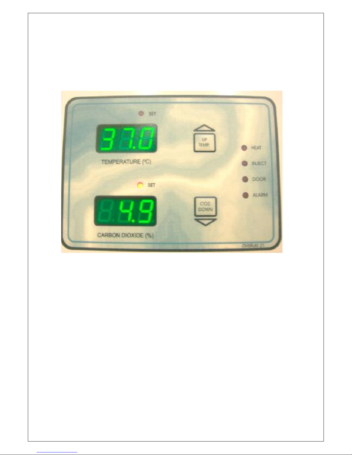
OPERATING CONTROLLER:
This example will demonstrate how to set the cabinet for the following
conditions:
Temperature = 37.0oC Carbon Dioxide = 5.0%
TO SET TEMPERATURE
Press and hold the TEMP button. The display will blank for 2 seconds, release
the button. The SET LED above the temperature display will turn on indicating
that this parameter is now in the temperature set mode and the current set point
will be displayed. Use the UP and DOWN buttons to adjust the Set Point to
37.0oC.
When the adjustment is complete the controller will return to normal operation if
the buttons are not pressed. This is indicated by the TEMP SET LED going off.
TO SET THE CO
2
CONCENTRATION
Press and hold the CO2button. The display will blank for 2 seconds, release
the button. The SET LED above the CO2display will turn on indicating that this
parameter is now in the set mode and the current set point will be displayed.
Use the UP and DOWN buttons to adjust the set point to 5.0%.
When the adjustment is complete the controller will return to normal operation if
the buttons are not pressed. This is indicated by the CO2SET LED going out.
HEPA FILTER (If Fitted): To change the HEPA Filter, undo the two
knurled nuts holding the filter to the inside top tray and withdraw the
filter.
RELATIVE HUMIDITY
There is no electronic control of humidity in these enclosures, the humidity is
maintained either by placing a small plastic tray of water in the tray support and
attaching this to a vacant shelf ladder near the bottom of the cabinet or by
partially filling the large stainless tray on cooled units. The humidity level will
usually equilibrate to a relative humidity of above 80%. (typically 60% - 70% on
Tropicool and Cooled units.

MANUALP/4000_SERVICE_0712 July2012
12
To display the Relative Humidity (Non INFRA-RED Models ONLY): Press
the CO2button momentarily and the CO2display will indicate the %RH. After a
few seconds the display will return to displaying the CO2reading.
CONDENSATION:
It is normal for a small amount of condensation to appear on the side walls
and glass door(s) and floor when operating with humidities above 85%
RH. Any water accumulating on the floor of the cabinet should be
removed at regular intervals.
CAUTION: This chamber has been fitted with a SPECIAL UVC Sterilising lamp
located behind the stainless steel rear duct. Note that this ULTRA-VIOLET
lamp is HARMFUL to the eyes and MUST NOT be viewed directly or indirectly
for any period.
The lamp is automatically turned OFF when the outer door is opened and turns
ON for 5 minutes when the door is reclosed.
CONFIRMATION OF OPERATING PARAMETERS
Contherm check the Temperature, and CO2calibration in the factory in the final
testing stages. For your confidence it is advisable to obtain your own calibration
so as to ensure the enclosure is operating to your satisfaction. This must be
carried out in the enclosures final operating environment. A full procedure for
calibrating the enclosure in given in the CALIBRATION Chapter.
TROPICOOL UNITS:
This type of cabinet is fitted with Contherm’s ‘Tropicool’ peltier cooling option.
The Tropicool unit uses a peltier cooling device to obtain lower temperatures,
typically allowing operation to 5oC below ambient. The ‘Tropicool’ unit runs
continuously.
COOLED UNITS:
This type of cabinet is fitted with a special refrigeration unit, the lowest
temperature of which is factory set via a ‘evaporator pressure regulator’ to
minimise the dehumidifying effect of the cooling coils. The minimum attainable
temperature will be about +15oC. The refrigeration unit runs continuously.
MANUALP/4000_SERVICE_0712 July2012
13
ALARMS
There are TWO types of alarm used in the Contherm Mitre series enclosures.
Standard Alarms and Special Alarms
STANDARD ALARMS
[1-.-] [2-.-] [4-.-] [5-.-] [6-.-] [7-.-] [8-.-] [11.-] [12.-]
These alarm numbers indicate a problem with cabinet control, ie. overtemperature, faulty sensor ,etc.
To CANCEL all the alarms except [2-.-] Press and Hold the TEMP button until
the temperature display blanks. To cancel the [2-.-] alarm, press and hold the
CO2button until the CO2display blanks. To assist any service enquiries later
please note the number of the alarm and what was done to eliminate the cause.
SPECIAL ALARMS
[3-.-] [9-.-]
These alarms can ONLY be cancelled by using the procedure outline below.
These alarms indicate that the cabinet may have lost some of its settings [3-.-],
OR that Electrical Interference [9-.-] has corrupted the cabinets internal
operating system.
To cancel the [3-.-] or [9-.-] alarms it is necessary to go into SET MODE and
check both Temperature and CO2set points. Once the set points of the CO2and
Temperature and the Temperature calibration has been checked the alarms will
cancel.

MANUALP/4000_SERVICE_0712 July2012
14
POWER CONTROL AND HI-LIMIT PANEL (RIGHT HAND SIDE)
The Power Control and Hi-Limit Panel is fitted at the top right hand side of the
enclosure. This panel contains the ON/OFF Switch, FUSE and user adjustable
Temperature HI-LIMIT thermostat.
1 CO
2
SAMPLE PORT
This fitting allows the user to SAMPLE the atmosphere inside the cabinet.
The fitting cover MUST be fitted after sampling to minimise CO
2
loss.
Note: A sample should NOT be taken within 5 seconds of the CO
2
INJECT LED coming on.
2 TEMPERATURE HI-LIMIT THERMOSTAT
This is a mechanical thermostat which directly monitors the temperature
of the enclosure. If the temperature exceeds this setting the power to the
element will be switched off and the associated Hi-Limit (3) neon will
illuminate when the controller applies power to the element. This can be
observed by watching the HEAT LED on the front panel. This thermostat
should be set to operate just above the set point temperature. See
Setting Hi-Limit Thermostat below.
3 HI-LIMIT NEON
This RED neon lights whenever the Hi-Limit Thermostat is activated.
Whenever the neon is illuminated no power is being supplied to the
enclosure heating elements (this is an additional safety against
inadvertent enclosure overheating).
4 ON/OFF SWITCH
This turns the power on or off. The fitting also contains an electrical
noise filter.
5 FUSE : The fitting contains a 5AMP fuse.
6 POWER LEAD SOCKET: The power lead plugs into this socket.
7 FRIDGE ON/OFF SWITCH:
If fitted, this turns the fridge on or off. When operating at 37oC in an airconditioned room, it is recommended to set the ‘FRIDGE Switch’ to OFF.
1 2
3 4 5 67
MANUALP/4000_SERVICE_0712 July2012
15
OPERATING CONTROL PANEL
The Control Panel on the outer door is used to access the operating conditions
for the enclosure.
UP/TEMP
This button is used to increase the parameter value, to display the enclosure
Temperature and the Temperature set point. This will sometimes be referred to
as the TEMP or the UP button.
DOWN/CO
2
This button is used to decrease the parameter value, to display the CO2 set
point and the Relative Humidity (Non INFRA-RED Models ONLY). This will
sometimes be referred to as the CO2or the DOWN button.
SET
These LED’s indicate if the Temperature or CO2displays are in SET MODE.

MANUALP/4000_SERVICE_0712 July2012
16
HEAT
Indicates when power is being supplied to the heating element. This will remain
steady when large changes in conditions are occurring eg warming up or if the
door has been opened. When the enclosure is at the temperature set point, the
LED will pulse.
INJECT
Indicates when CO2is being injected. This will usually be accompanied by an
audible click of the CO2inject solenoid.
DOOR
Indicates that the outer door is open. If the door is opened a door switch is
activated, the internal fan, heater and CO2solenoid are disabled until the door is
closed. Leaving the outer door ajar for prolonged periods will affect the internal
control of the cabinet atmosphere.
ALARM
Indicates when an ALARM condition has been triggered. The alarm will be
accompanied by a beep and will display the Alarm Code in the Temperature
Display.
MANUALP/4000_SERVICE_0712 July2012
17
SECTION 5 CALIBRATION
It is important to note that the calibration of this enclosure is valid only when it is
calibrated in its final operating environment. Contherm calibrates the enclosure
to our internal standards in the final testing stages of manufacture. This means
that when the enclosure arrives at the customer site, the calibration carried out
in the factory may no longer be valid. Contherm wishes to make it clear that
calibration is a CUSTOMER responsibility. Contherm has ensured that a
complete acceptable calibration procedure is available for the customer to
follow.
Calibration of the enclosures is achieved by checking the enclosure temperature
display against a customer supplied calibrated thermometer and CO
2
monitoring device. It is important that the calibration is carried out at the
temperature of interest.
The temperature sensor that is used by the electronic thermal control system is
also used to indicate the control temperature. This sensor is in the duct of the
air circulation system and is not directly in the work space, therefore it is
necessary to adjust any offset between the work space and the indicated
temperature. Calibration entails adjusting the CALIBRATION FACTOR so that
the work space temperature matches the indicated temperature. The
CALIBRATION FACTORS are stored in an Electrically Erasable Read Only
Memory (EEROM). EEROM retains its stored memory even with the power off.
TEMPERATURE CALIBRATION
1 Place a calibrated reference thermometer that has been checked to the
customers satisfaction into the enclosure. The usual place for this is in
the centre of the work space. Place it so that it is able to be read without
opening the glass inner door.
2 Ensure the enclosure has stabilised at the temperature of interest for at
least 6 hours.
3 Press and hold the TEMP button until the display momentarily blanks,
this will access the SET POINT mode and the SET LED above the
temperature display will be on.
4 Press both TEMP and CO2buttons at the same time. The temperature
display will show [Cal] for 2-3 seconds and then show the current
temperature.
5 Adjust the value displayed to read the same as your reference
thermometer.

MANUALP/4000_SERVICE_0712 July2012
18
6 Release all buttons. After about 3 seconds the temperature display will
show [---] then a HEXIDECIMAL number for about 2 seconds (This
number may be noted as a reference to the current calibration) then
another [---] and beep. The enclosure will now begin to adjust itself so
that the reference thermometer temperature matches the SET POINT
temperature. The indicated temperature will show a temperature offset
from the SET POINT Temperature immediately after the calibration. This
is normal as the controller is now endeavoring to match the SET POINT
to the work space reference thermometer.
The procedure may need to be repeated to obtain the best final calibration.
The temperature should be recorded on a daily basis by placing a thermometer
in the workspace so that it can be read without opening the inner glass doors
and the long term temperature performance can then be plotted to give an
assurance of correct temperature performance. Similarly, the CO2should be
checked and monitored regularly using the independent monitor. Record these
for long term assurance.
CO2CALIBRATION – THERMAL CONDUCTIVITY SENSOR
There are two modes of calibration for the THERMAL CONDUCTIVITY CO
2
system. An AUTO-CALIBRATION (AUTO-CAL) and MANUAL CALIBRATION
(MAN-CAL). Both types perform the same operation. AUTO-CAL enables the
enclosure to perform the calibration at ‘quiet’ times of operation, whereas MAN-
CAL is used when the cabinet has been empty of CO2for a long period. Both
require the enclosure to be stabilised at the desired set Temperature.
AUTO-CAL
The normal method of calibrating the CO2concentration is by using the
AUTO-CAL facility. To force the controller to carry out an AUTO-CAL the
following procedure is recommended.
1 Change the Temperature Set Point by 0.1oC (eg. if your normal operating
Temperature Set Point is 37.0oC change it to 36.9oC).
2 The CO2display should now be flashing, this indicates that the CO2is
now out of calibration. Note that the operation of the CO2gas inlet
solenoid(s) will be inhibited while the CO2display is flashing.
3OPEN both the outer and inner incubator doors, and leave them open for
at least 30 seconds. (This is to flush the enclosure of CO2gas).
4 CLOSE both doors.
MANUALP/4000_SERVICE_0712 July2012
19
5 CHANGE the Temperature Set Point back to your normal setting, ie.
37°C
6LEAVE the enclosure (preferably without opening the doors) until the
CO2display stops flashing. This indicates that normal CO2control has
returned.
MAN-CAL
1 Flush the enclosure of CO2by opening the doors for at least 30 seconds.
2 Press and Hold the CO2button until the CO2display momentarily blanks.
3 Press both the TEMP and CO2buttons together until the display shows
[Cal].
4 Release all buttons and wait. The display will show [---] and beep. The
CO2display will automatically reset itself to [0.3%] when the current
temperature next reaches the Temperature Set Point.
NOTE AUTO-CAL and MAN-CAL will assume that there is no CO2in the
enclosure when the calibration sequence begins.
CO
2
SPAN CALIBRATION
As there is no facility to adjust the span of the CO2display, it is necessary to
check the CO2concentration by independent means and if necessary REPEAT
the AUTO-CAL procedure until satisfactory calibration is achieved.
CONTHERM recommends a FYRITE is used to check the CO2concentration.
Any other means that is satisfactory to the customer may be substituted.
1 Let the enclosure stabilise at its operating conditions for at least 6 hours.
2 Monitor the CO2level via the CO2SAMPLE PORT with the independent
CO2monitor ensuring that the CO2injection solenoid does not operate
during the sampling time. Note the reading of the independent monitor.
3 If the MONITOR value is within ± 0.5% of the DISPLAYED CO2 reading
no further action is necessary.
4 Repeat the AUTO-CAL calibration procedure until a satisfactory result is
achieved.

MANUALP/4000_SERVICE_0712 July2012
20
Notes on Calibration Procedures for THERMAL CONDUCTIVITY Sensors
• The CO
2
SET POINT can be left as it is for the duration of the AUTO-CAL
and MAN-CAL calibration sequences. Once the CO
2
display has stopped
flashing the controller will adjust the workspace CO2level to the SET POINT.
• AUTO-CAL is best done last thing at night as the calibration usually takes
from 1 to 4 hours to complete.
• CONTHERM recommends that AUTO-CAL is carried out at least every two
months OR if a Temperature Calibration has taken place.
CO2CALIBRATION – INFRA-RED CO2SENSOR (IR)
There are two modes of calibration for the INFRA-RED CO2system. A USERCALIBRATION and FACTORY CALIBRATION. Use the user calibration for
small calibration adjustment and can be carried out via the front panel buttons.
The factory calibration is used when the user calibration can not obtain the
correct result and when the sensor is replaced and is carried out by qualified
service personnel. Both require the enclosure to be stabilised at the desired set
Temperature. A detailed IR calibration procedure can be found on Servicing
Section.
USER IR CO2CALIBRATION
This is used for small calibration adjustments (approx ±0.5%) and may be
carried out by the user via the front panel buttons.
Press and hold the CO2button until the display momentarily blanks, this will
access the SET POINT mode and the SET LED above the temperature display
will be on.
Press both TEMP and CO2buttons at the same time. The temperature display
will show [Cal] for 2-3 seconds and then show the current co2reading.
Adjust the value displayed to read the same as your reference co2monitoring
device.
When exiting the user calibration routine a calibration constant (0.0 to 3.2) will
be displayed, this number should be noted down.
MANUALP/4000_SERVICE_0712 July2012
21
FACTORY IR CO2CALIBRATION
(For use only if correct result cannot be obtained from USER Calibration)
These adjustments are normally carried out by a qualified service person and
require a DC Voltmeter.
There are two modes of calibration for the infra-red CO2system.
1. Zero Offset Calibration (This should never require adjustment)
2. Span calibration. (This may require a slight adjustment if the CO2 calibration
is incorrect)
NB:These adjustments do not calibrate the accuracy of the CO2concentration
measurement, but only adjust the output to match the measuring device.
Before carrying out these procedures insure that the cabinet has been allowed
to stabilise for at least 6 hours.
Before attempting these settings the CALIBRATION CONSTANT should be
centered to read 1.6 to allow for maximum user adjustment from the front
panel in the future.
E.G If the user calibration constant is 0.9 the easiest way to get it to read 1.6
is to follow the user calibration routine but when adjusting the calibration value
press the ‘UP’ button seven times (0.9 + 7 = 1.6). Wait for the calibration
constant to be displayed, if it doesn’t read 1.6 repeat above (either UP or
DOWN) until it does.
CO
2
ZERO OFFSET CALIBRATION
To adjust the ZERO of the CO2display, it is necessary to proceed as follows:
1 Connect a voltmeter to the CO2sensor board output terminals.
2 With JP5 OPEN, connect the shorting jumper onto pins of JP4, use the
‘UP’ or ‘DOWN’ buttons on the CO2PCB to adjust the voltmeter to read
0.005 volts DC. (The cabinet display will read about 0.2% CO2)
3 REMOVE the shorting jumper from pins of JP4.
CO2SPAN CALIBRATION
To adjust the SPAN of the CO2display, it is necessary to proceed as follows:
1 Connect a voltmeter to the CO2sensor board output terminals (V0 &
COM).
2 With JP5 CLOSED, connect the shorting jumper onto pins of JP4, use
the ‘UP’ or ‘DOWN’ buttons on the DCS-300 INFRA-RED CO2PCB to
adjust the voltmeter to read 0.650 volts DC. (The cabinet display will read

MANUALP/4000_SERVICE_0712 July2012
22
about 16.5% CO2). This value may be raised or lowered to achieve the
exact CO2calibration result. (‘Normal’ range is from 0.550 – 0.750). If the
cabinet display is reading too high when the CO2concentration is
compared with a test instrument (‘Fyrite’ etc) then the reference voltage
should be adjusted slightly DOWN.
Just press either the ‘UP or ‘DOWN’ button VERY briefly and then WAIT
for the meter reading to change as the reading will lag the button press
by several seconds.
3 REMOVE any shorting jumpers from pins of JP4 & JP5. Recheck
calibration if necessary.
MANUALP/4000_SERVICE_0712 July2012
23
VERIFYING CABINET PERFORMANCE
There are two basic tests that may be carried out to verify cabinet performance.
NB: These tests MUST be carried out with the cabinet EMPTY and at the
specified ambient of +20
o
C.
TEMPORAL PERFORMANCE:
The cabinet should be set to operate at the Contherm specified calibration
conditions.
Temporal performance is tested by placing a suitable (calibrated) test probe in
the centre of the workspace and recording the readings for up to 1 hour AFTER
the cabinet has FULLY STABILISED. The cabinet has fully stabilised when the
average temperature is no longer increasing or decreasing over time.
The result should be within the quoted specification. This result is a function of
the cabinet control system, sensor and airflow.
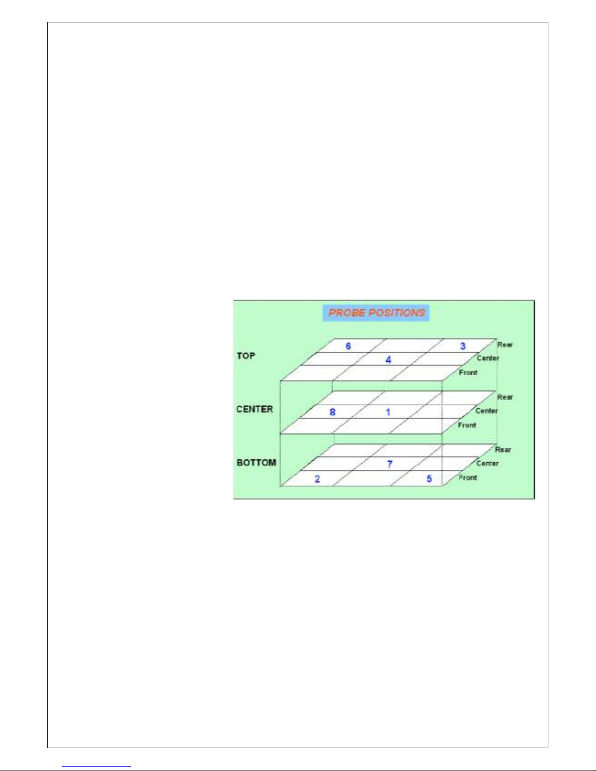
SPATIAL
PERFORMANCE:
The cabinet should be
set to operate at the
Contherm specified
calibration conditions.
Check Spatial Variation
@ 37
o
C
(Refer manual for
specification, 8 points
as per diagram)
Spatial performance is
tested by placing
suitable (calibrated) test
probes (usually
thermocouples) in the eight specified positions and recording the readings for up
to 1 hour AFTER the cabinet has FULLY STABILISED. The cabinet has fully
stabilised when the average temperature is no longer increasing or decreasing
over time.
The sensors must be no closer than 30mm to any wall or roof and must be
above the lowest shelf position by at least 30mm.
The spatial test must be performed with all doors, vents etc CLOSED and the
measuring sensors must be very closely matched at the specified temperature.
 Loading...