

Page 1
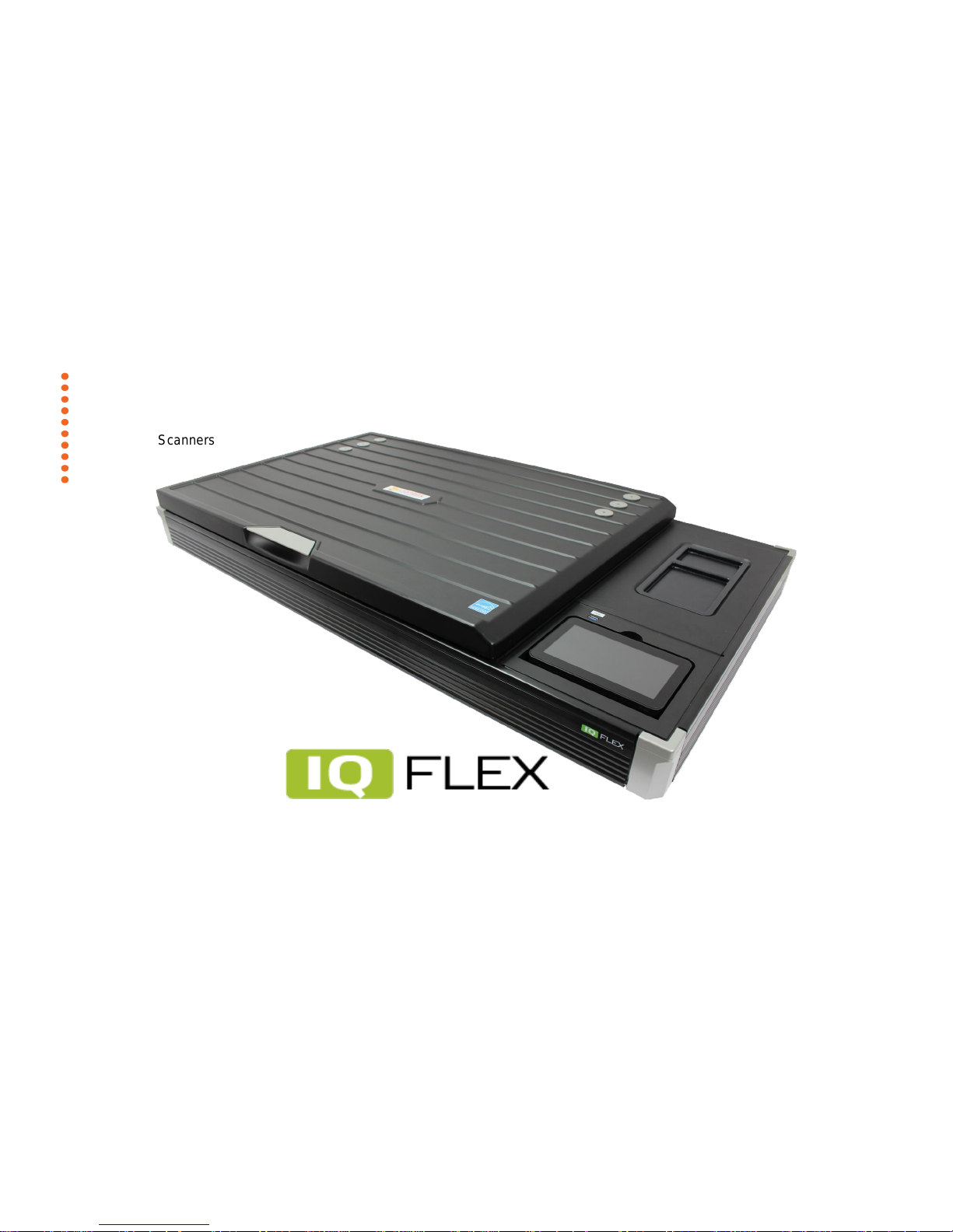
Model: IQ FLEX
Technical Service Guide
Wide Format Scanners
Page 2

Page | 2
Contents
1 Information. ............................................................................. 3
1.1 Revision Table. ........................................................................................ 3
2 Design. .................................................................................... 4
2.1 Electronics. .............................................................................................. 4
2.2 Adjustments. ........................................................................................... 4
2.3 Tools Required. ....................................................................................... 5
2.4 Block Diagram. ........................................................................................ 6
2.5 Wiring Diagram. ..................................................................................... 7
3 Troubleshooting ..................................................................... 8
Image Quality problems. .................................................................................... 8
3.1 Troubleshooting your scanner ................................................................ 9
3.2 Problems with the scanner installation................................................. 10
3.3 Problems operating the scanner ........................................................... 11
3.4 Problems with the scan result ............................................................... 14
3.5 Troubleshooting Sequence .................................................................... 15
3.6 Image Quality Problems. ....................................................................... 16
4 Power Supply (external). ...................................................... 18
5 Scanner Controller Board Layout (SULN & SULO). ........... 19
6 Part Replacement ................................................................. 20
6.1 Identifying Parts. ................................................................................... 20
6.2 Top Lid Plate (and adjustment) ............................................................. 21
6.3 Side Covers and Side Panels .................................................................. 26
6.4 Rear Panel ............................................................................................. 33
6.5 Touchscreen Cover Panel ....................................................................... 36
6.6 Touchscreen........................................................................................... 40
6.7 Top Rear Panel ...................................................................................... 45
6.8 Glass Plate ............................................................................................. 48
6.9 Motor Unit ............................................................................................. 59
6.10 Carriage Home Sensor ........................................................................... 65
6.11 CIS Carriage ........................................................................................... 70
6.12 Controller Board Panel .......................................................................... 83
6.13 Controller Board .................................................................................... 91
6.14 Power Switch and Connector ................................................................. 97
7 Procedures ......................................................................... 103
7.1 Replacement Main Board Setup .......................................................... 103
7.2 Updating Firmware ............................................................................. 107
7.3 Service Package ................................................................................... 110
7.4 Full Calibration .................................................................................... 112
8 Scanner Terms ................................................................... 115
9 Temporary Board Swap ..................................................... 127
9.1 Problem with Activation ...................................................................... 127
Page 3

Page | 3
1 Information.
1.1 Revision Table.
1.0
Original Issue of Document.
11/07/2017
GJV / DB
1.1
Updated Touchscreen and Lid instructions
18/09/2017
GJV
Document Title.:
TA53D Technical Service Guide
Doc. No.:
FSM/TSG/???? (Don’t know how this is created!)
Prepared by.:
GJV / DB
Distribution.:
Contex
Issue revision date.:
1.1
Date:
18/09/2017
Scanners covered by this Service Guide.:
IQ FLEX
This document is the property of Contex A/S. The data contained herein, in whole or in part, may not be duplicated, used or disclosed outside the Recipient
for any purpose other than to conduct technical evaluation. This restriction does not limit the Recipients right to use information contained in the data if it is
obtained from another source without restriction.
Page 4

Page | 4
2 Design.
2.1 Electronics.
Block Diagram.
Wiring Diagram.
Circuit board layouts.
CIS Carriage Construction.
2.2 Adjustments.
Belt tension.
Page 5
Page | 5
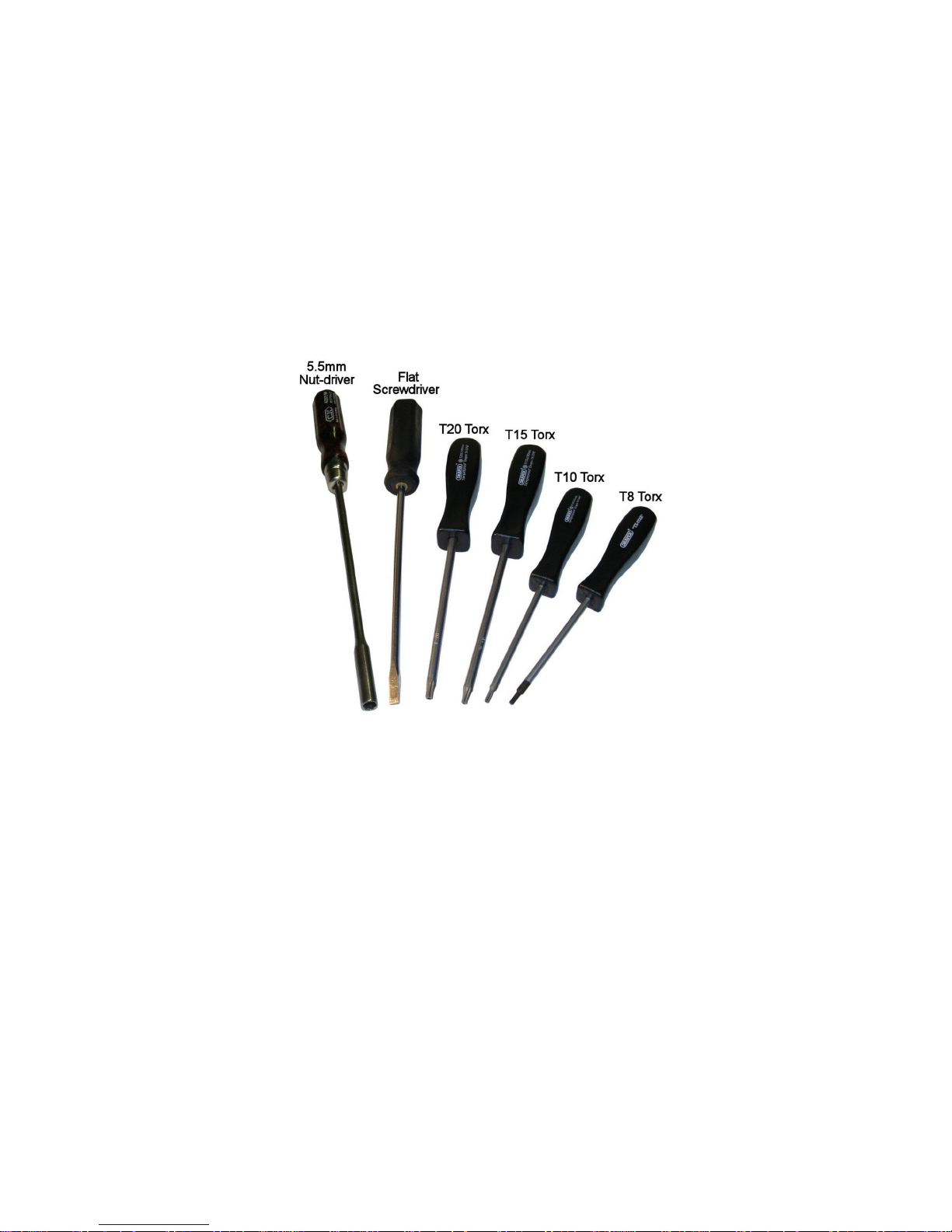
2.3 Tools Required.
Page 6
Page | 6
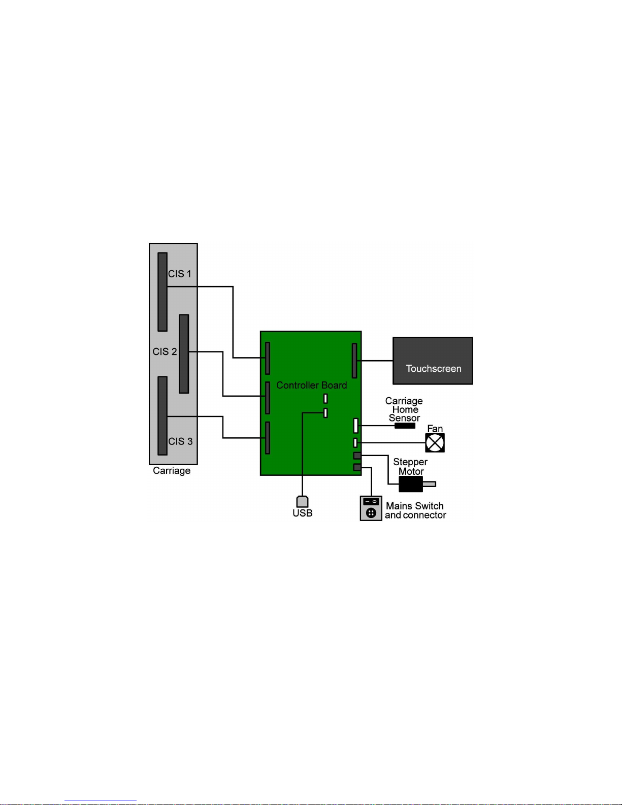
2.4 Block Diagram.
Page 7
Page | 7
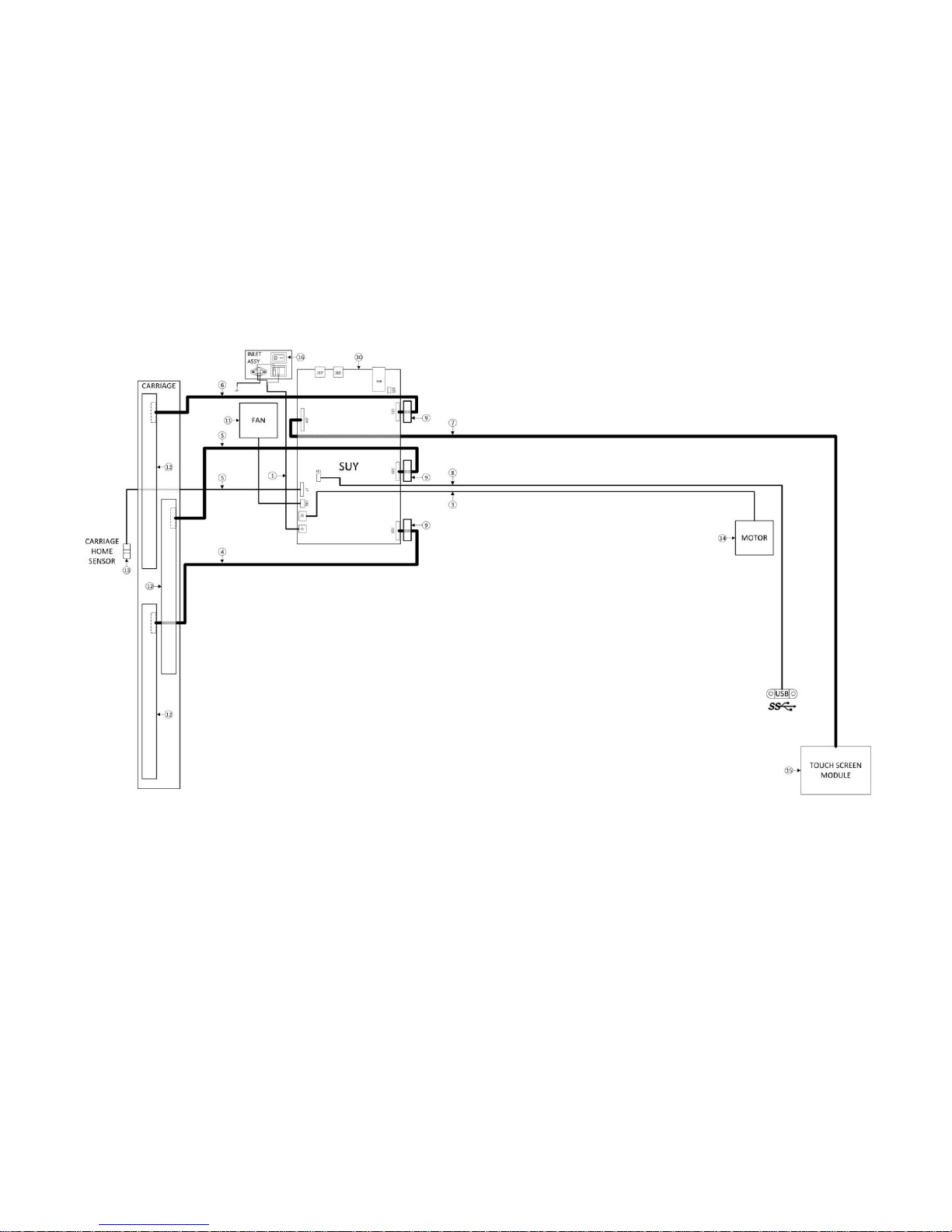
2.5 Wiring Diagram.
Page 8

Page | 8
3 Troubleshooting
Troubleshooting your Scanner
Problems with the scanner installation
Problems operating the scanner
Problems with the scan result
Troubleshooting Sequence.
Banding Problems.
Image Quality problems.
Banding Problems
Crumpled Paper or Folds
Dust Problems
Stitching Problems
Page 9
Page | 9
3.1 Troubleshooting your scanner
This section describes trouble-shooting procedures for the most common issues. Please look for a problem description that matches your actual situation. If
found, perform the recommended trouble-shooting procedures.
3.1.1 Technical Support
In some cases you may need technical assistance.
In order to get the best and fastest solution to your problem, you should prepare as much information as possible before requesting a support ticket.
1. Write down your scanner model name and serial number. The serial number is printed on the label on the underside of the scanner’s lid. Open the lid
to view the label.
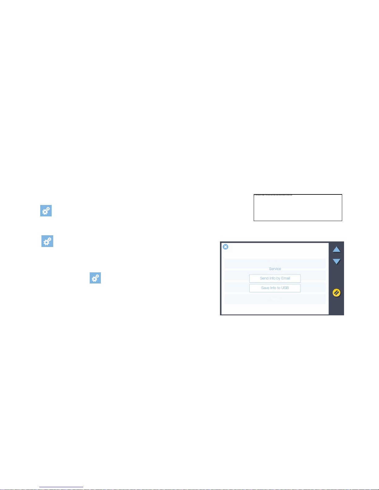
2. Write down your Firmware and software versions: If your software interface is up and running select:
-> About
3. Write down your Contex LINK (client software) version – Open the Contex LINK software on your PC. The version number is displayed at the top.
4. Write down the scanners IP address. This could be useful for getting remote support online. To see the scanner’s IP select
-> Scanner -> Network
5. To help technical service solve the issue as fast as possible, you can additionally
provide log files containing important data from your scanner.
6. To supply the scanner logs:
7. Select the Settings icon: -> Scanner -> Service
8. Select your method for saving or sending the log files:
a. Select Send info by email to send log files to [email protected]. This
requires that the outgoing email server settings are applied and your scanning
is running. See section Installation for details.
b. Choose Save info to USB to copy the log files to a USB key that you insert in
the scanner top.
Page 10

Page | 10
3.2 Problems with the scanner installation
Problem
Possible Causes and Remedies
Error message during Scanner Calibration
This message may appear when running the Calibration wizard.
1. The most common cause is a dirty or smudged glass plate. Clean the scanning
area, reboot the scanner and then complete the calibration steps as described in
the section Full Calibration in this guide.
2. If the problem persists after cleaning the scanning area - the problem could be
caused by a loose object in the optical path. Remove any torn pieces of paper or
other loose objects from the scanning area. Even the smallest loose objects will
disturb the scanner adjustment function.
Contact your technical service provider if the problem persists.
Cannot scan to a cloud service
You get a message on the scanner screen: “Welcome to Contex LINK, <cloud service
name> is not enabled”
1. Ensure that you have installed the Contex LINK client software on your PC, and
that you have setup the parameters for the specific cloud service.
2. If you have made the settings, test your login credentials to the cloud service from
your PC.
3. Repeat the cloud service setup in Contex LINK.
Ensure that you have the latest version of the Contex LINK software on your PC. If not,
update Contex LINK and repeat above steps.
Can’t find myself as a user on the scanner
You scroll through the available users on the scanner screen and cannot find yourself
as a user. Try the following steps:
1. Ensure that you have installed the Contex LINK client software on your PC, and
that you have setup the user parameters correctly.
2. Restart the scanner to let it redetect all users on the LAN.
If the above fails, update the Contex LINK software on your PC and repeat above
steps.
Page 11
Page | 11
3.3 Problems operating the scanner
Problem
Possible Causes and Remedies
I can’t find my scan files after scanning
You selected scan to PC or scan to a cloud service but you cannot locate your scan
file.
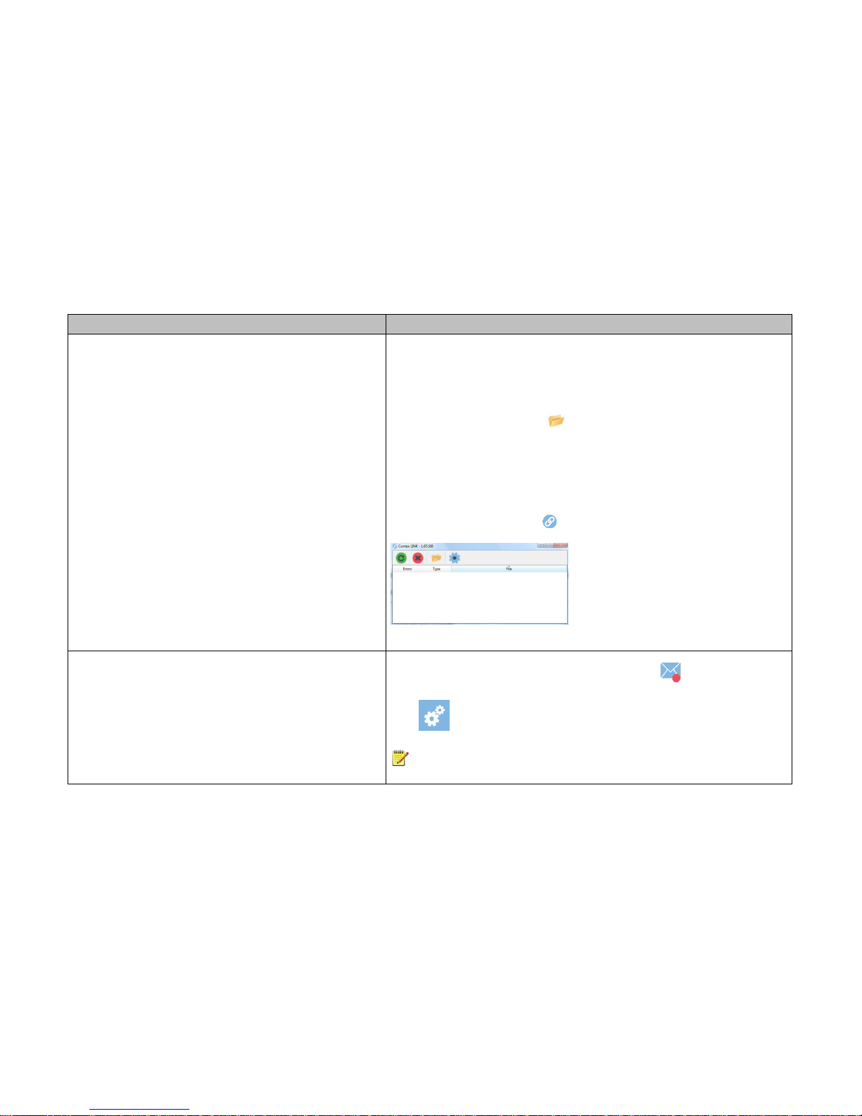
1. If is running correctly you can locate your files in the following location for each
destination:
a. Scan to PC: Select the folder icon at the top of the Contex LINK scan client
interface to access the file
b. Scan to cloud service Box: the Contex Solutions folder in the root
c. Scan to cloud service Google Drive: the Contex Solutions folder in the root
d. Scan to cloud service OneDrive: the Contex Solutions folder in the root
e. Scan to cloud service Dropbox: the Contex Solutions folder in the Apps folder
2. If the file transfer failed you will see the file listed in the Contex LINK error log.
Start Contex LINK on the PC to view.
Contex LINK error log
I cannot scan to email
You selected scan to email and entered the right email address. But you receive an
error and the scanner email icon is marked with a red dot.
The outgoing mail may not be configured correctly in the scanner.
Go to -> System -> Email to control the outgoing email settings
NOTE: The Email settings relate to the company’s IT and its email solution and
usually will require support from the IT expert.
Page 12

Page | 12
Problem
Possible Causes and Remedies
Scanning: The colors in my scan are not correct in relation to the
original document
Please carry out a calibration of the scanner. Calibration adjusts the color settings.
1. Thoroughly clean the scanning area. See Cleaning the scan area for instructions.
2. Run the calibration wizard and follow the steps described in the section Scanner
Calibration in this guide.
3. Be sure to choose Full Calibration
Copying: The colors in my printed output were not copied correctly
in relation to the original document
1. Make sure that the Media setting matches the media loaded in the printer. If they
are wrong, correct to the right media.
2. If you have used the correct Media setting in the Copy settings, you should
recreate a new media profile:
a) Thoroughly clean the scanning area.
b) Run the calibration wizard and steps as described in the section Full
Calibration in this guide. Be sure to choose full calibration.
Now create a new Media profile:
c) Select -> Printer
d) Select Media Profile to start the media profile wizard to create a new
media profile.
Follow the instructions on your screen.
Entire image is not scanned
Make sure that you are loading the original correctly:
1. Be sure to align the center of the original with the scanner center arrow mark.
2. Load with the printed side face up.
Page 13

Page | 13
Problem
Possible Causes and Remedies
Large empty areas on both sides of the image
Go to the Area option in your scan settings before pressing the green go button.
The All setting means that the scanner will disregard the original’s size and capture
the whole scanner width which will add white space on both sides of the document.
Select Auto if you only want to scan the width of the loaded document.
One or more thin vertical lines (in the direction of paper feeding)
show up in the scanned image, but not in the original document.
This is often caused by an unclean glass plate. Even a single spec of dirt in the wrong
spot on the glass plate can cause a streak along your entire scan. To remedy:
1. Clean your glass plate and rollers as described in this users’ guide under Cleaning.
2. Most of the dirt on the glass plate comes from the documents that are passed
against it. Wipe the document clean with a dry lint-free cloth before feeding the
document into the scanner.
3. If the problem persists after cleaning, calibrate the scanner. The scanner may have
memorized dirt specs and you will need to recalibrate after removing the dirt.
4. If the problem persists after cleaning and calibration –Check the glass plate for
scratches. A damaged glass plate should be replaced. Obtain a new glass plate
from your service provider. Follow the steps in the user’s guide to replace the glass
plate with a new one.
5. A damaged calibration sheet can also cause streaks. Obtain a new sheet and
recalibrate the scanner
Page 14

Page | 14
3.4 Problems with the scan result
Problem
Possible Causes and Remedies
Whole image not scanned
1. Check in your scanning application that your size settings are either for Auto
detection or correspond to the size of the whole original.
2. Check that you are loading the original correctly from the scanner’s right side.
One or more thin vertical lines show up in the scanned image, but
not in the original drawing.
This is often caused by an unclean glass plate. Even a single spec of dirt in the wrong
spot on the glass plate can apply a streak along your entire scan. To remedy:
1. Clean your glass plate as described in this users’ guide.
2. Most dirt on the glass plate is introduced by the documents. Wipe clean the
document with a dry lint-free cloth before feeding the document into the
scanner.
3. If the problem persists after cleaning, calibrate the scanner. The scanner may
have memorized dirt specs and you need to recalibrate after dirt-removal.
4. If the problem persists after cleaning and calibration –Check the glass plate for
scratches. A damaged glass plate should be replaced. Contact your service
provider for information.
5. A damaged calibration sheet can also cause streaks. Obtain a new sheet and
recalibrate the scanner.
Page 15
Page | 15
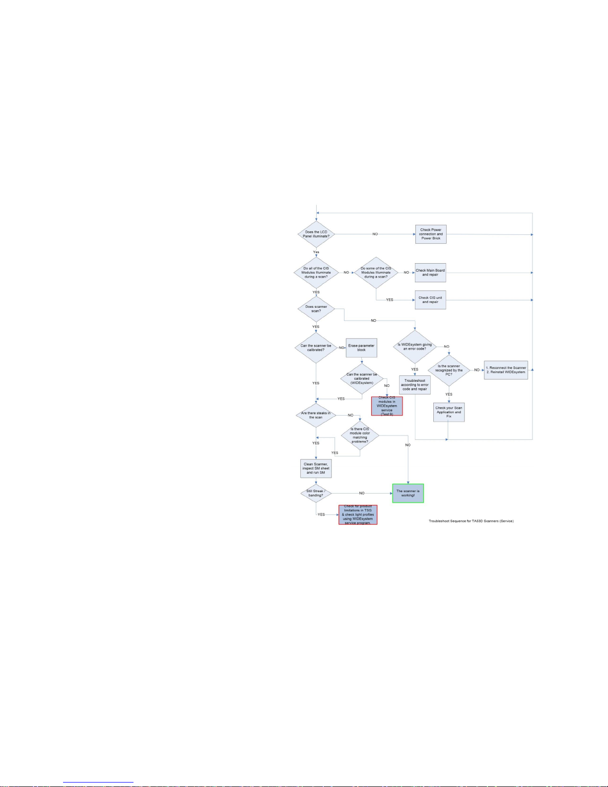
3.5 Troubleshooting Sequence
This is a suggested Troubleshooting Sequence and will work in
most cases. There are always some grey zones, especially if the
problem is related to image quality.
Page 16
Page | 16
3.6 Image Quality Problems.
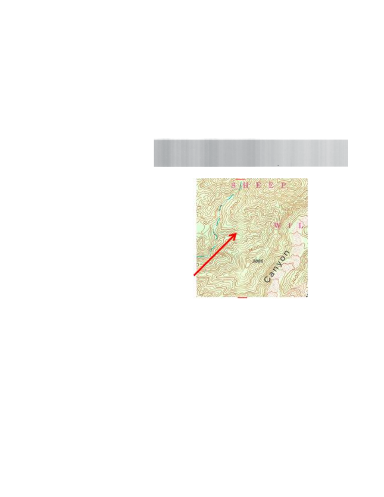
3.6.1 Banding Problems.
Bad/no grey balance calibration (CIS module to
module match).
Running WIDEsystem calibration should resolve
this problem in most cases.
3.6.2 Crumpled Paper or folds
Scanning originals that have folds or are
crumpled on CIS scanners is often confused as
a defect in the scanner, where it is actually a
limitation of the technology used. Due to the
very short distance from the sensor to the
surface of the original, referred to as the “Focal
Length”, if the document does not stay in
contact with the glass plate then it is very likely
to be out of focus.
Page 17
Page | 17
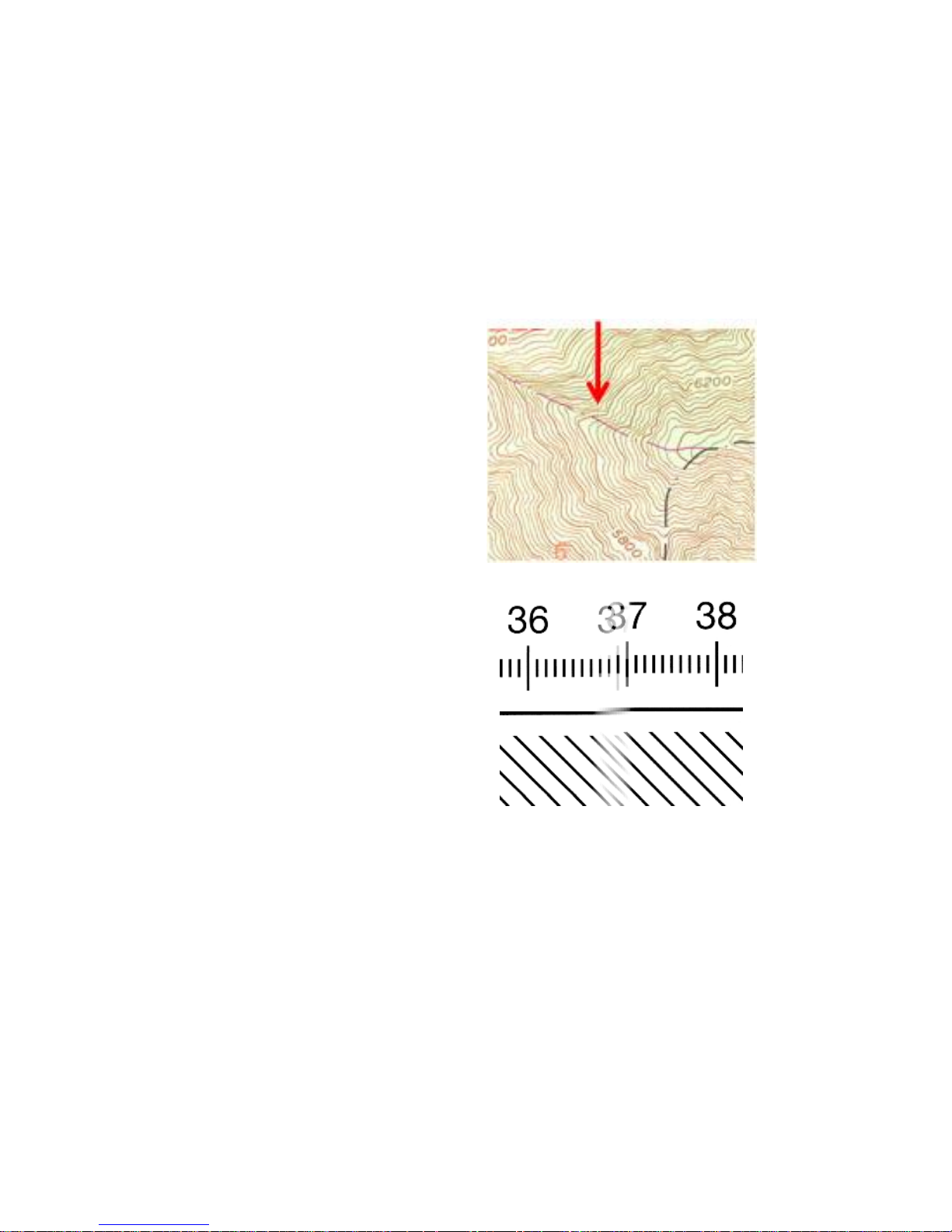
3.6.3 Dust Problems.
There are image quality problems that are not
related to HW errors. These could be due to
insufficient cleaning, bad calibration or
limitations in the CIS technology. Streaks
running in the scan direction could be caused
by dust on the surface of the CIS module.
Streaks that run in scan direction, that are color
independent or a lighter shade of the color, are
often related to the calibration. Check the
calibration sheet for scratches, clean the glass
plate and check the surface of the CIS for any
dust before running the WIDEsystem
calibration.
3.6.4 Stitching Problems.
Typically, the scanner simply needs to be
calibrated, either because the parameter block
has been erased, the scanner has never been
calibrated or the scanner has been moved
around. If re-calibrating the scanner does not
correct the stitching problem then check to be
sure the document is lying flat against the glass.
Stitching problem between 2 CIS modules.
Page 18
Page | 18
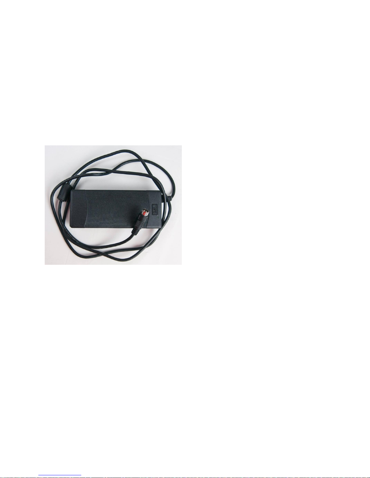
4 Power Supply (external).
The External Power Supply has a build in surge protection feature, if the
surge protection is triggered it will shut down for about 3 min before it will
recover.
The Power Supply is a +19 volt DC.
Page 19
Page | 19
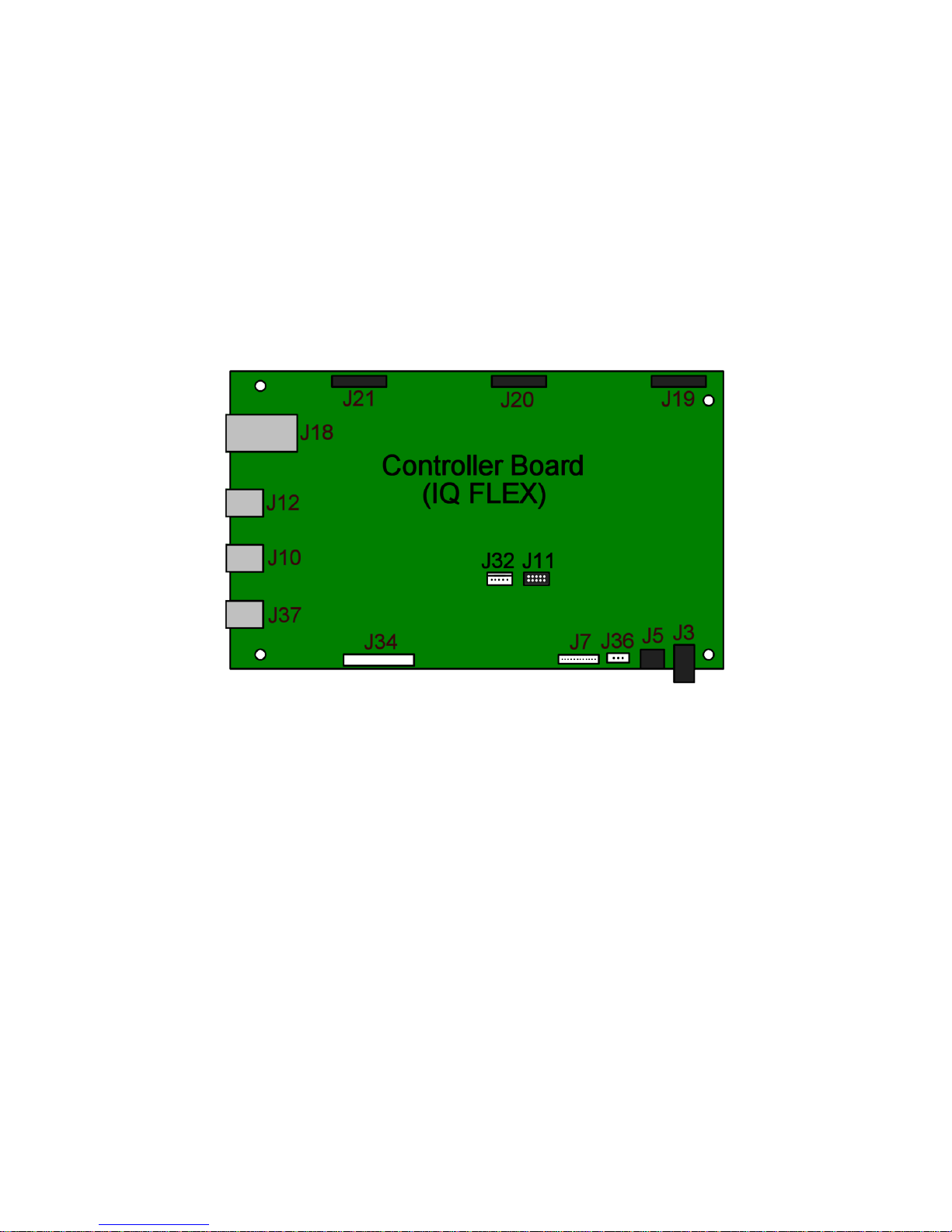
5 Scanner Controller Board Layout (SULN & SULO).
Page 20

Page | 20
6 Part Replacement
6.1 Identifying Parts.
Parts List.
Mechanics.
Top Lid Cover.
Side Covers and Side Panels.
Glass Plate
Top Lid Cover (including Control Panel)
Electronics.
Scanner Controller Board (SUV?).
CIS Carriage.
CIS Cables.
Stepper Motor Assy.
CIS Carriage Home Sensor.
Power Switch and Connector.
Touchscreen
Common Hand Tools.
Torx 10 Straight.
Torx 15 Straight.
Torx 20 Straight.
IMPORTANT Note!
Do not use power screwdrivers when working on the IQ FLEX, as these can operate with too much force and damage the screws and/or threads in
paneling. Hand operated screwdrivers are the only ones recommended to use.
Page 21
Page | 21
6.2 Top Lid Plate (and adjustment)
Tools Required:
None
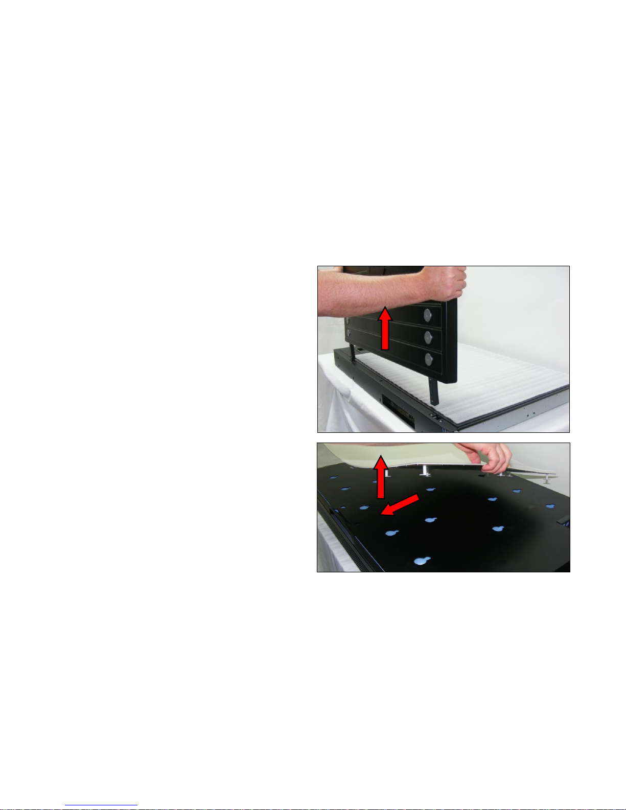
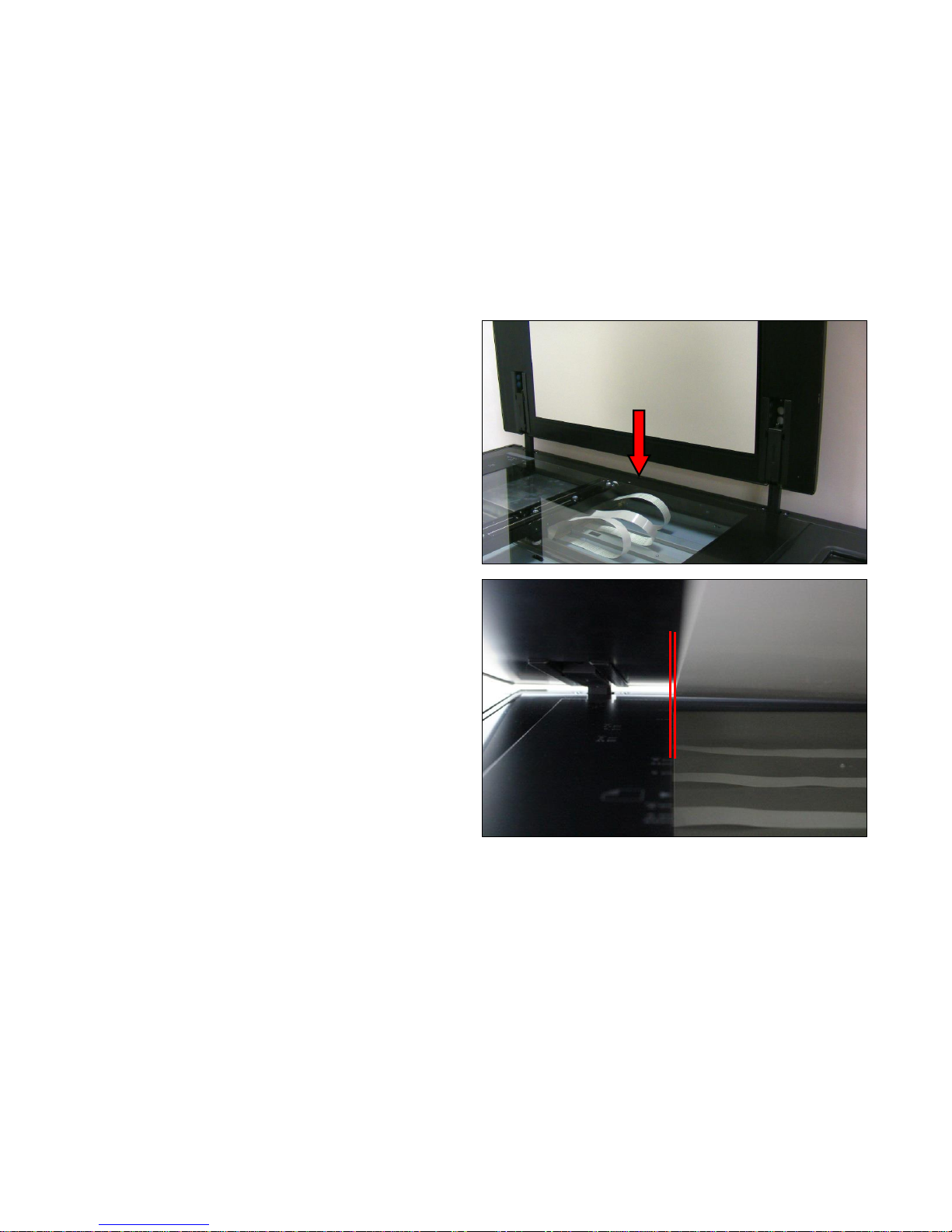
1. The Top Lid Plate simply lifts out of the recesses in the
rear panel
2. To replace the white hold down plate, slide the sheet
forward, and lift out of the slots. Replace in the reverse
order.
Page 22
Page | 22
3. Slide the Top Lid Plate brackets into the cutouts of the
rear panel.
4. After fitting a replacement Lid and/or White Plate, it may
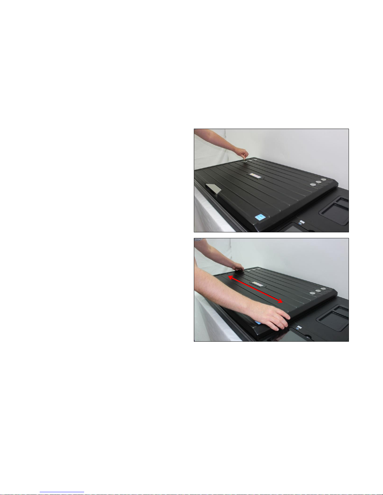
be necessary to make adjustments to the lid position.
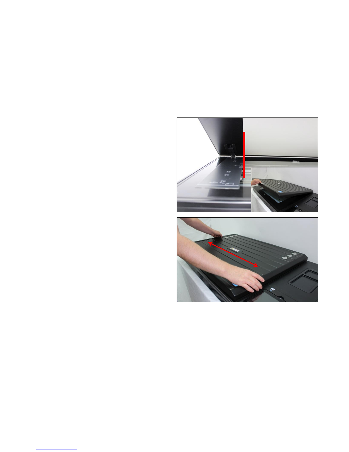
The edge of the White Plate, needs to be within 0.5 –
1mm (max) from the label.
Page 23
Page | 23
5. Loosen the 6 large diameter screws by half (approx.) a
turn. Do not remove the screws.
6. Physically move the lid unit in the required direction.
Page 24
Page | 24
7. Open the lid slightly, to check that the white plate is
between .5 millimeters and 1mm maximum away from
the edge.
8. Make readjustments if necessary.
Page 25
Page | 25
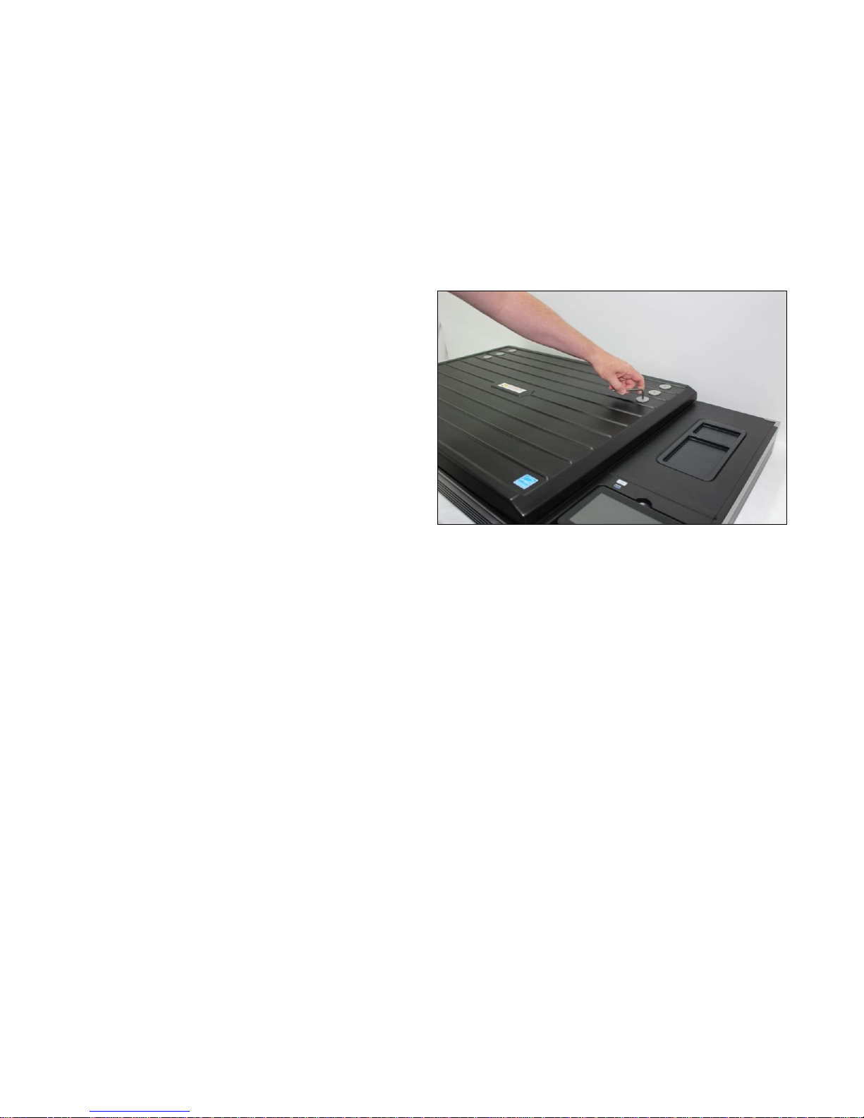
9. When the lid is correctly positioned, retighten the 6 large
diameter screws.
Page 26
Page | 26
6.3 Side Covers and Side Panels
Tools Required:
Flat Screwdriver
T10 Screwdriver
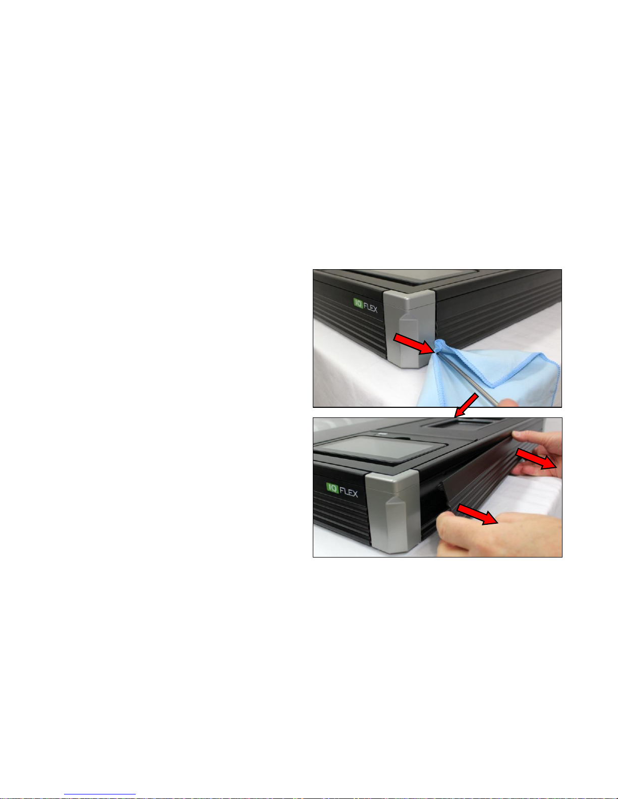
1. Use a soft cloth and flat screwdriver to prise off the edge
of the side covers
2. Gently pull the side cover from the edge of the scanner.
Page 27
Page | 27
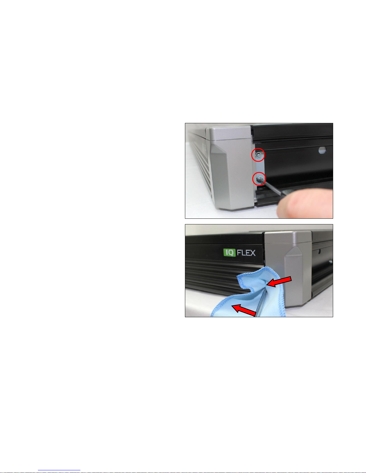
3. Remove the T10 screws from the length of the side
panel, including the 2 x screws holding the corner
bracket at both ends..
4. Remove all the side covers in the same way.
Page 28
Page | 28
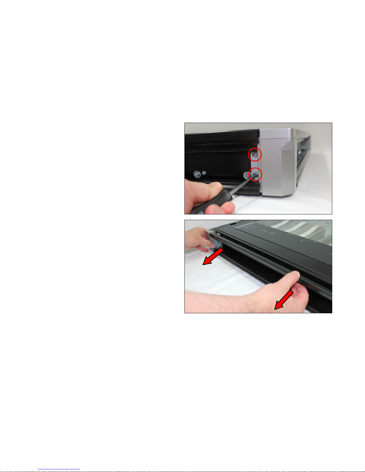
5. Remove the other 2 x T10 screws from the Corner
Bracket.
6. Pull the side panel, Make sure the Corner Brackets
come away with the side panel, not damaged.
Page 29
Page | 29
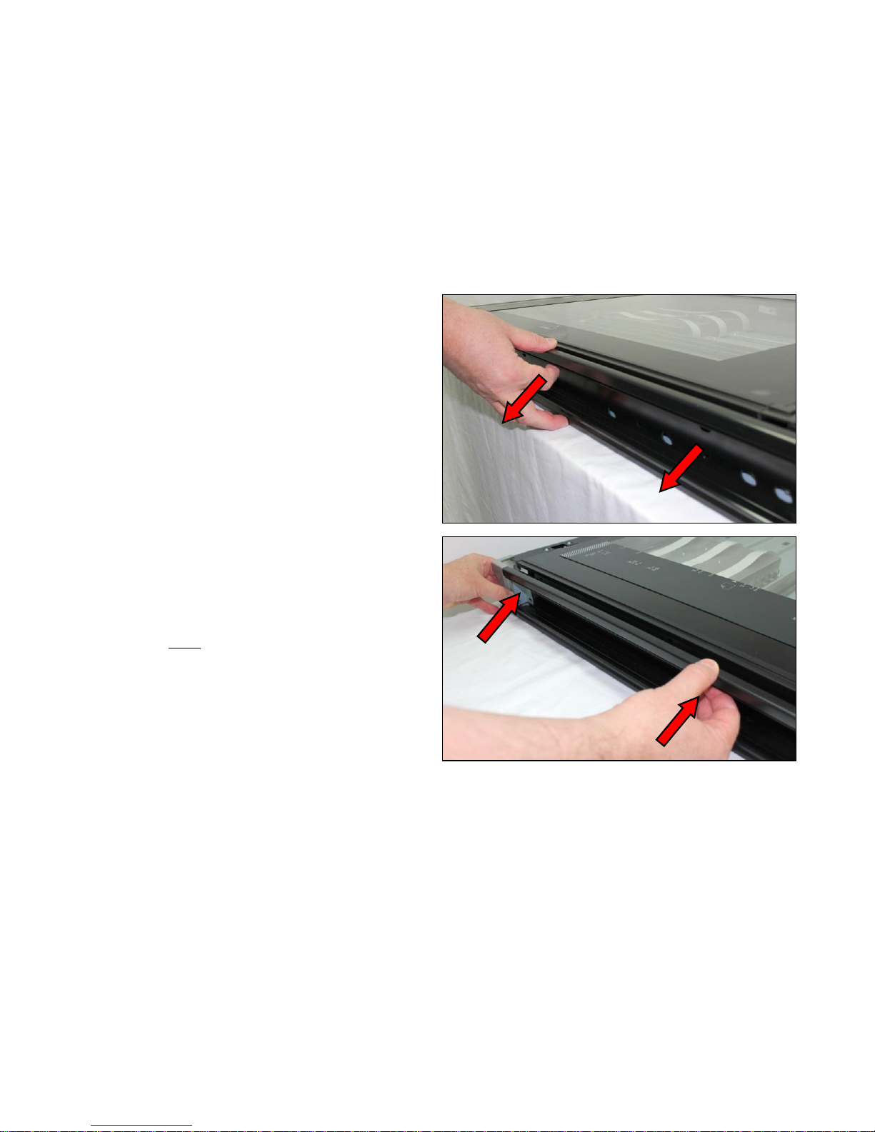
7. Remove all the side panel are removed in the same way.
8. To refit, make sure the Corner Brackets are lined up with
the rear panel, and pressed in firmly.
Page 30
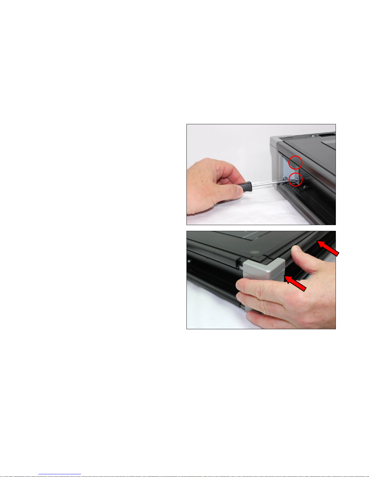
Page | 30
9. Refit the T10 screws to hold the Corner Brackets to the
chassis, then the remaining T10 screws along the panel.
Do not tighten these screws until all the panels are in
place.
10. Fit the other side panels, making sure the Corner
Brackets line up and press in firmly.
Page 31
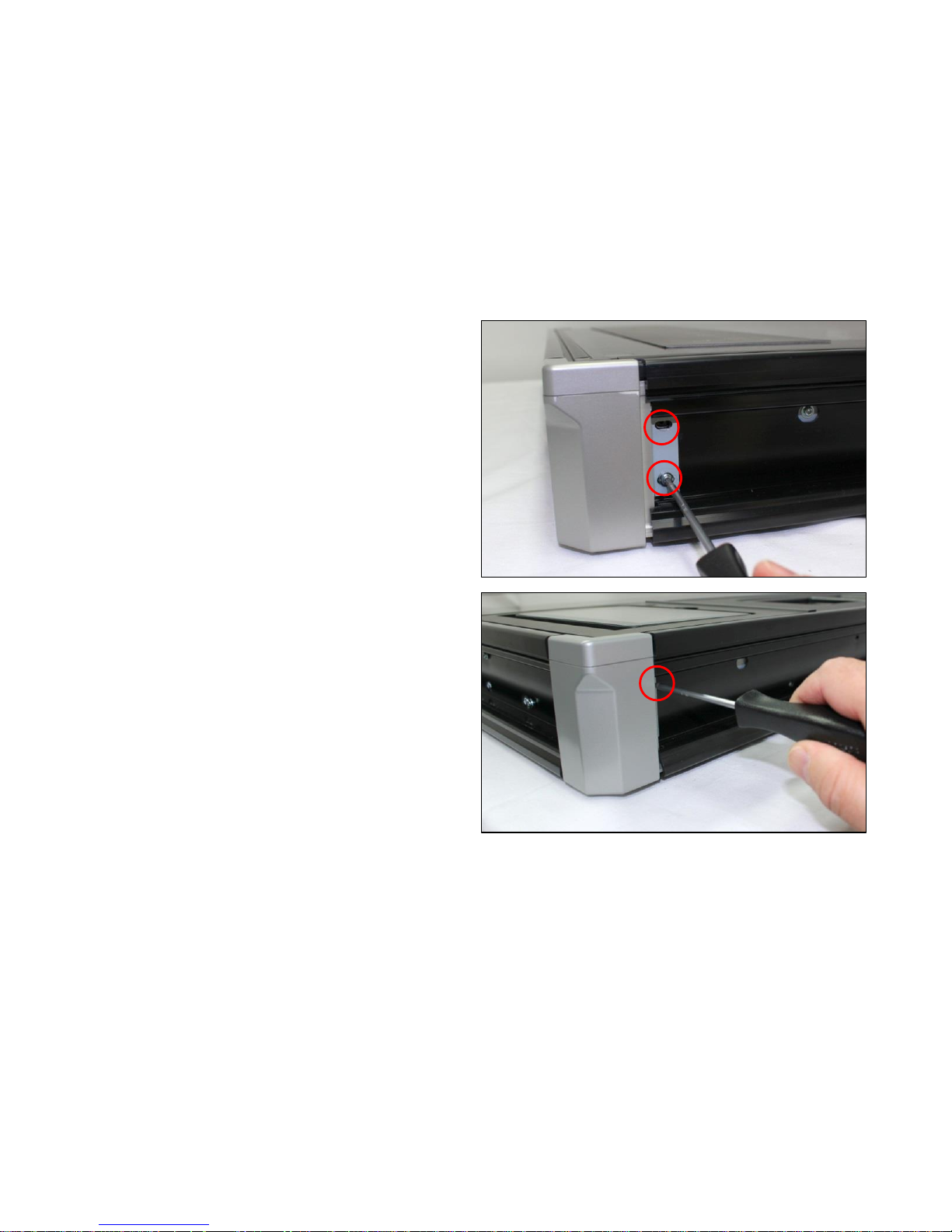
Page | 31
11. Fit the T10 screws into the Corner Bracket and all along
the side panel. Do not tighten the screws at this point.
Repeat for the removing side panel.
12. Once all the panels are fitted, and they are correctly
positioned, tighten up all the T10 screws just fitted.
Page 32
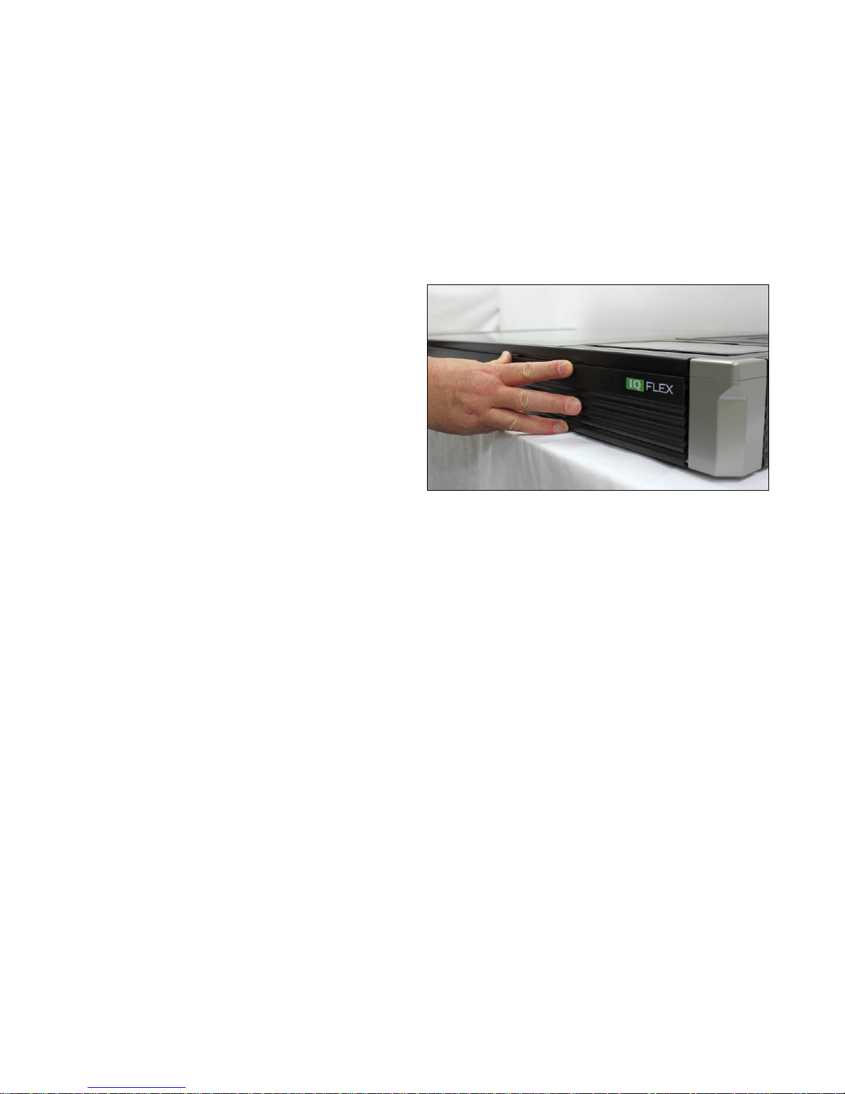
Page | 32
13. Refit all the side covers by simply pressing into place,
making sure the smooth part of the panel is towards the
top.
Page 33
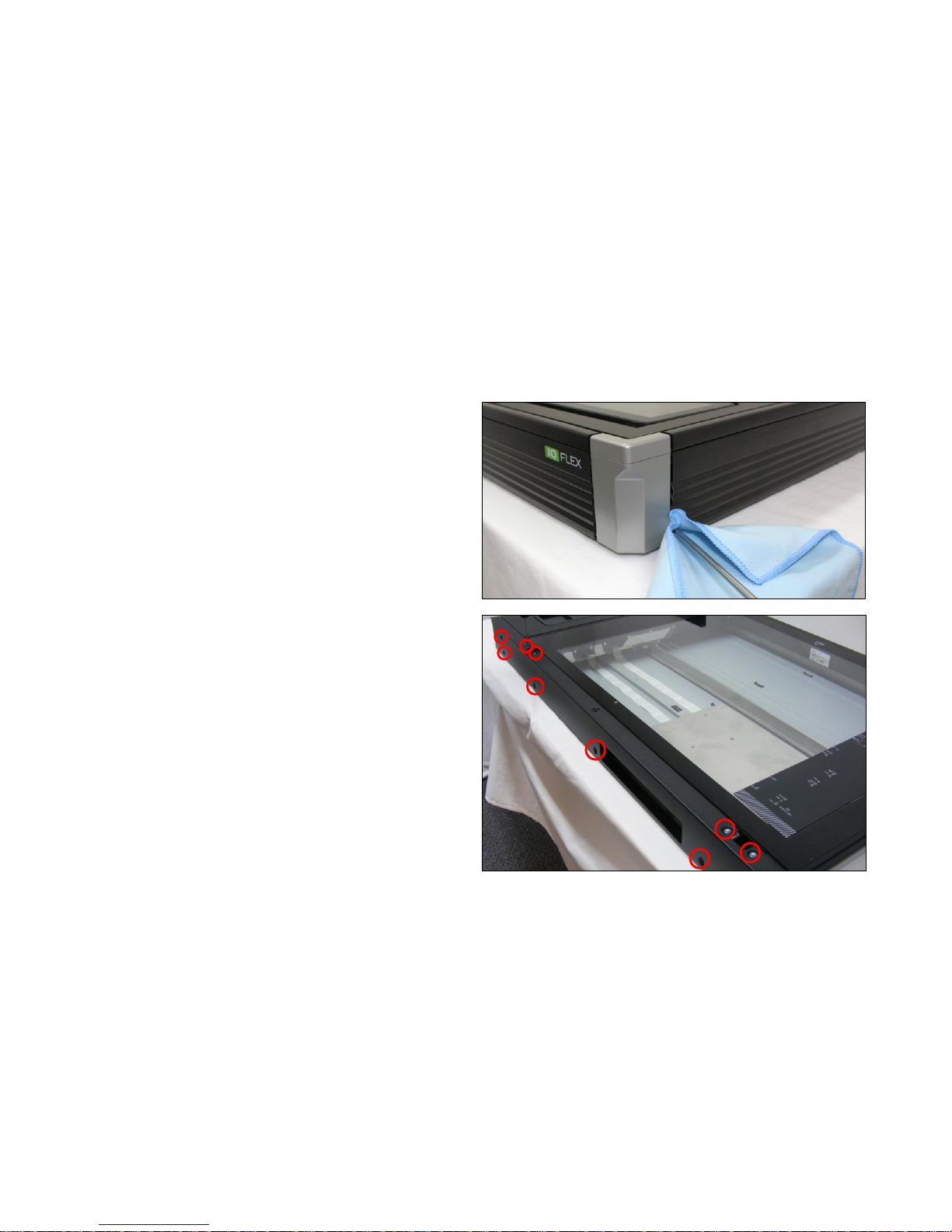
Page | 33
6.4 Rear Panel
Tools Required:
T10 Screwdriver
1. Remove the side covers and side panels as described in
‘
2. Side Covers and Side Panels
3. ’ page 26.
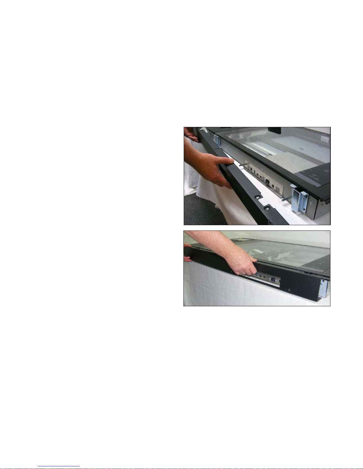
4. Remove the T10 screws along the length of the rear
panel.
Page 34
Page | 34
5. Remove the rear panel.
6. Refit the rear panel.
Page 35
Page | 35
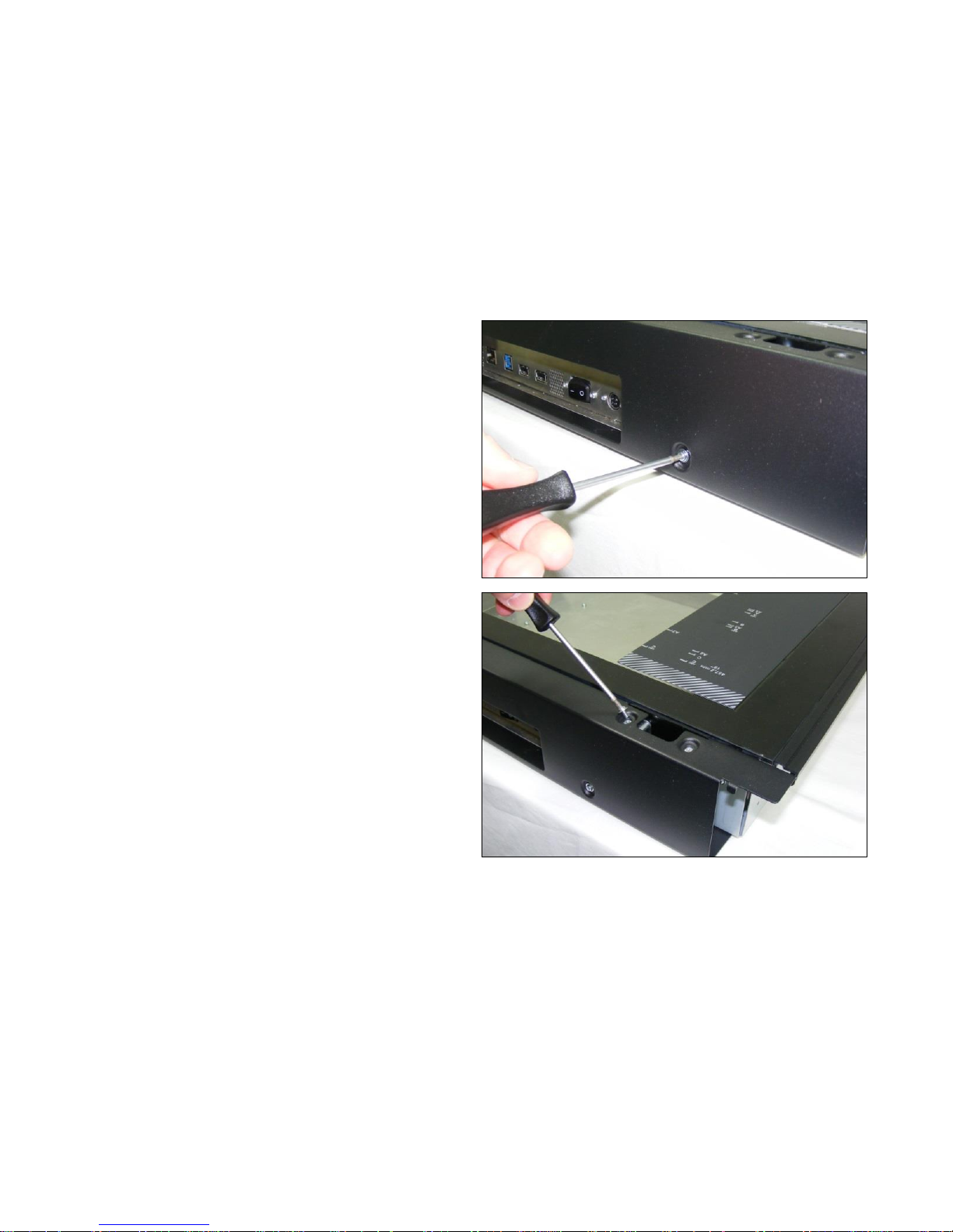
7. Refit the T10 screws along the side of the rear panel, but
do not tighten.
8. Fit the 4 x T10 screws either side of the Top Lid Cover
Hinge holes.
9. Making sure the rear panel is central on the scanner,
tighten all the screws.
Page 36
Page | 36
6.5 Touchscreen Cover Panel
Tools Required:
T10 Screwdriver
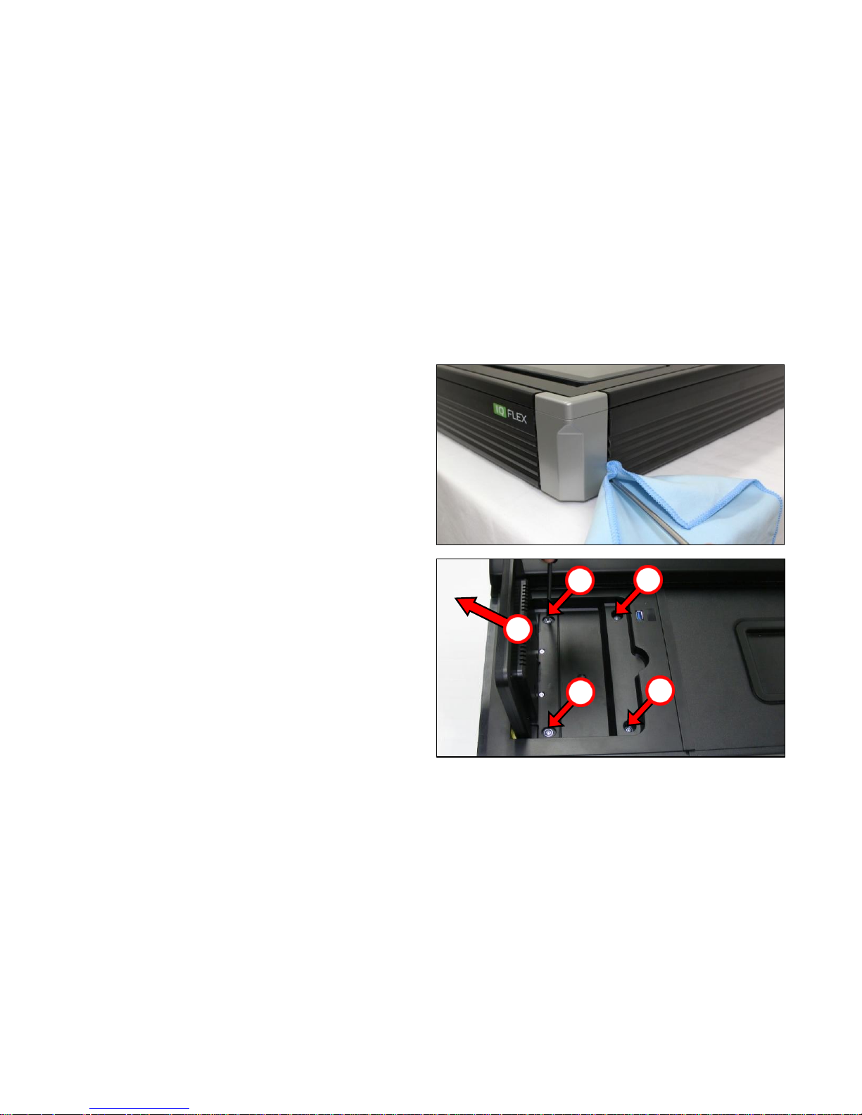
1. Remove the right hand and front covers and panels as
described in ‘
2. Side Covers and Side Panels
3. ’ page 26.
4. Lift the Touch screen panel into the upwards position.
5. Remove the 4 x T15 screws.
1
2
2
2
2
Page 37
Page | 37
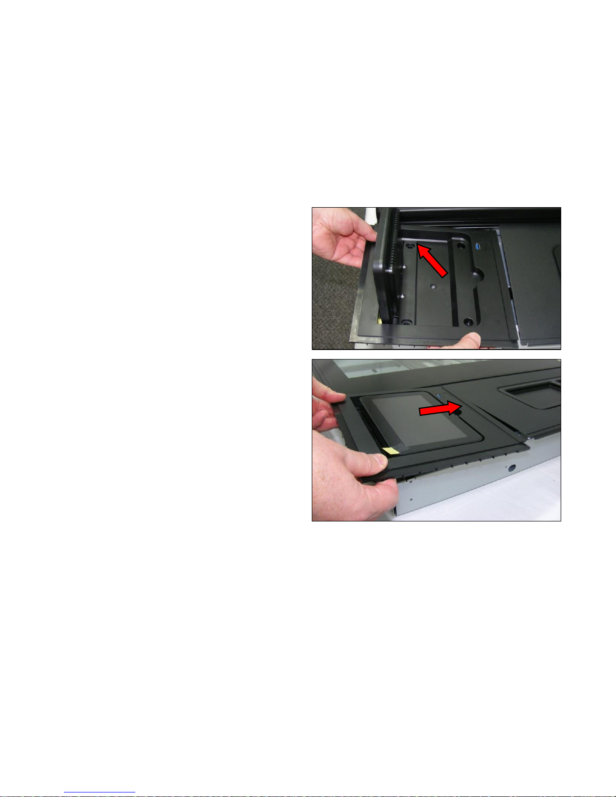
6. Carefully lift the panel, including the Touch Screen, out
of the chassis. As the Touch Screen is attached by the
cable to the Controller Board, move the panel away as
far as the cable will allow without causing any damage to
it.
7. When refitting, make sure the edges and grooves are
aligned and position into place.
Page 38
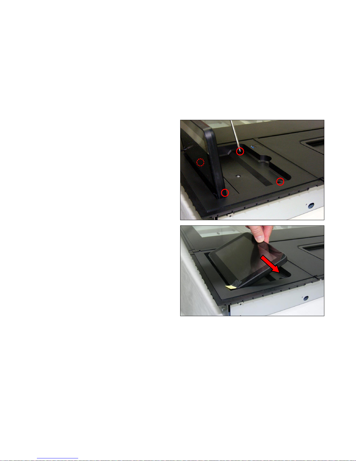
Page | 38
8. With the touchscreen lifted, replace the 4 x T20 screws.
9. Close down the touchscreen.
Page 39
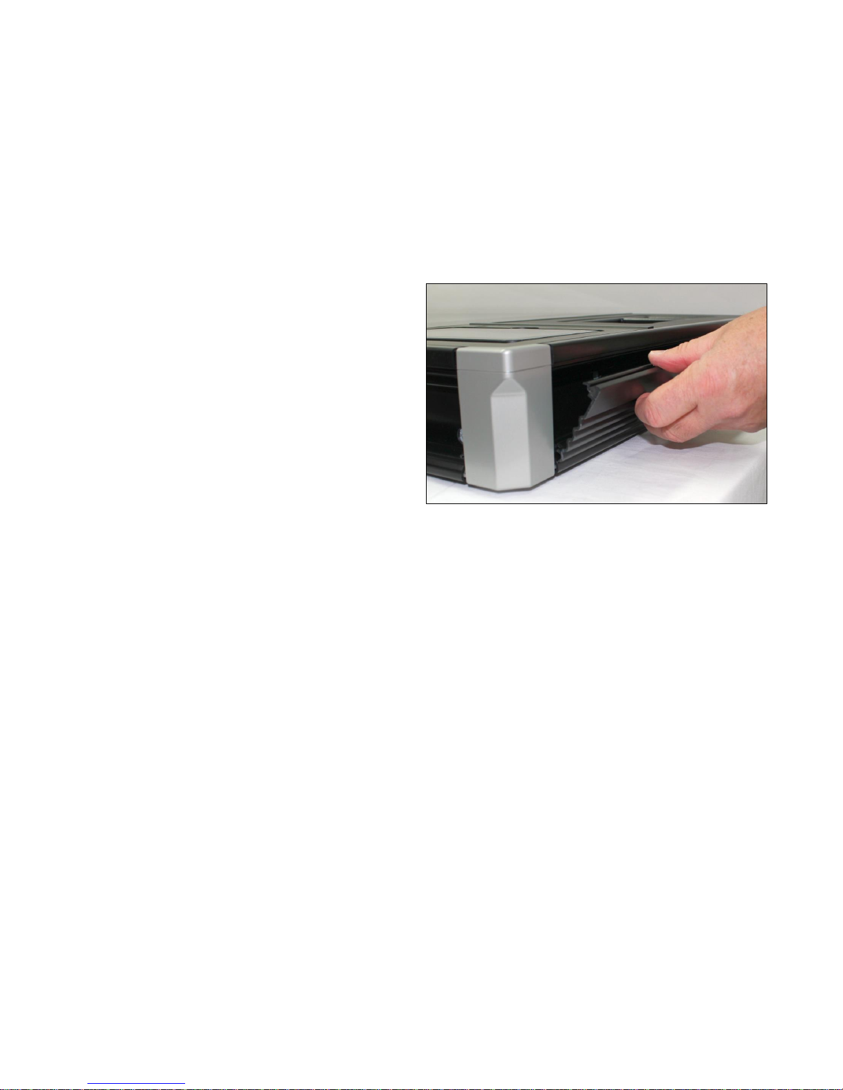
Page | 39
10. Refit the right hand and front covers and panels as
described in ‘
11. Side Covers and Side Panels
12. ’ page 26.
Page 40
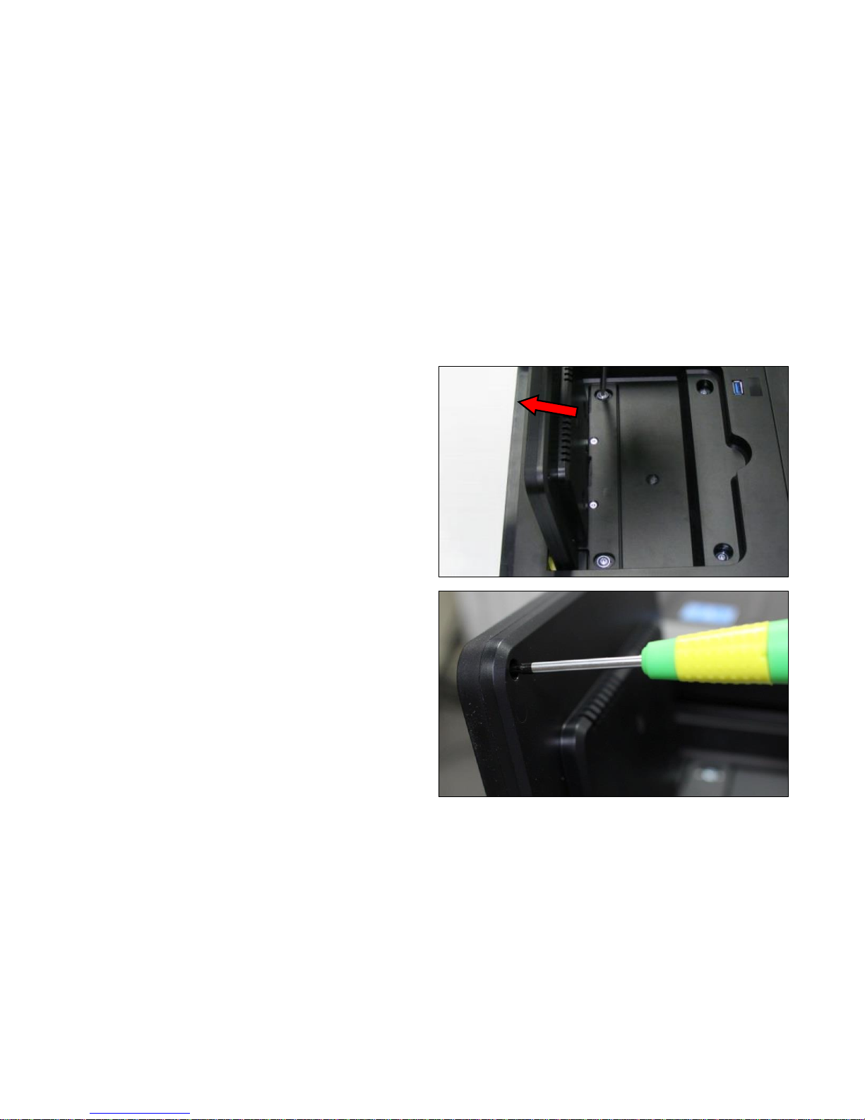
Page | 40
6.6 Touchscreen
Tools Required:
T6 Screwdriver
1. Lift the Touch screen panel into the upwards position.
2. Remove the 4 corner T6 screws from the back of the
Touchscreen panel.
Page 41
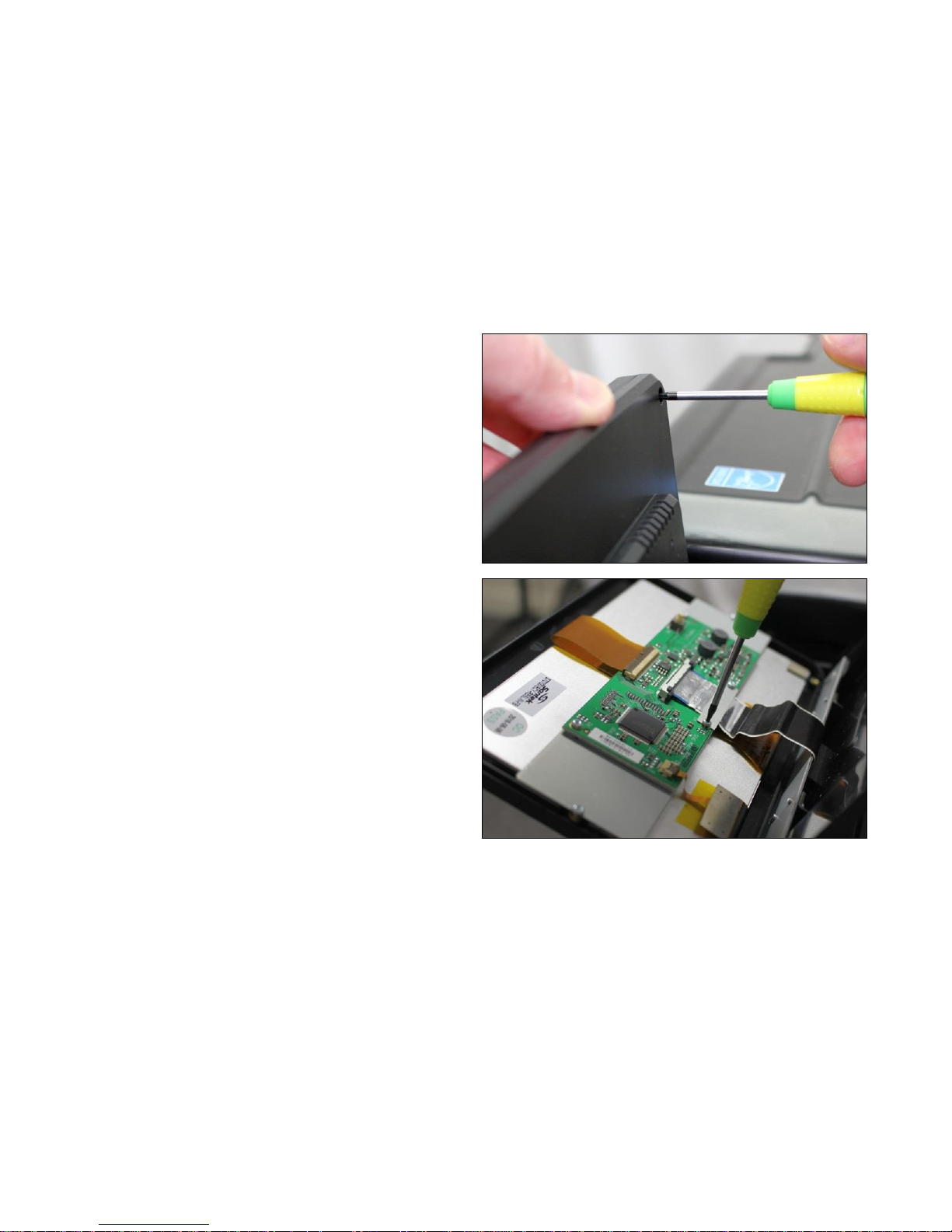
Page | 41
3. Hold the Touchscreen panel while taking the last screw
out to prevent it falling from the scanner, damaging the
cable.
4. Separate the touchscreen from the rear panel, and
remove the 2 T6 screws holding the cable retaining
bracket.
Page 42
Page | 42
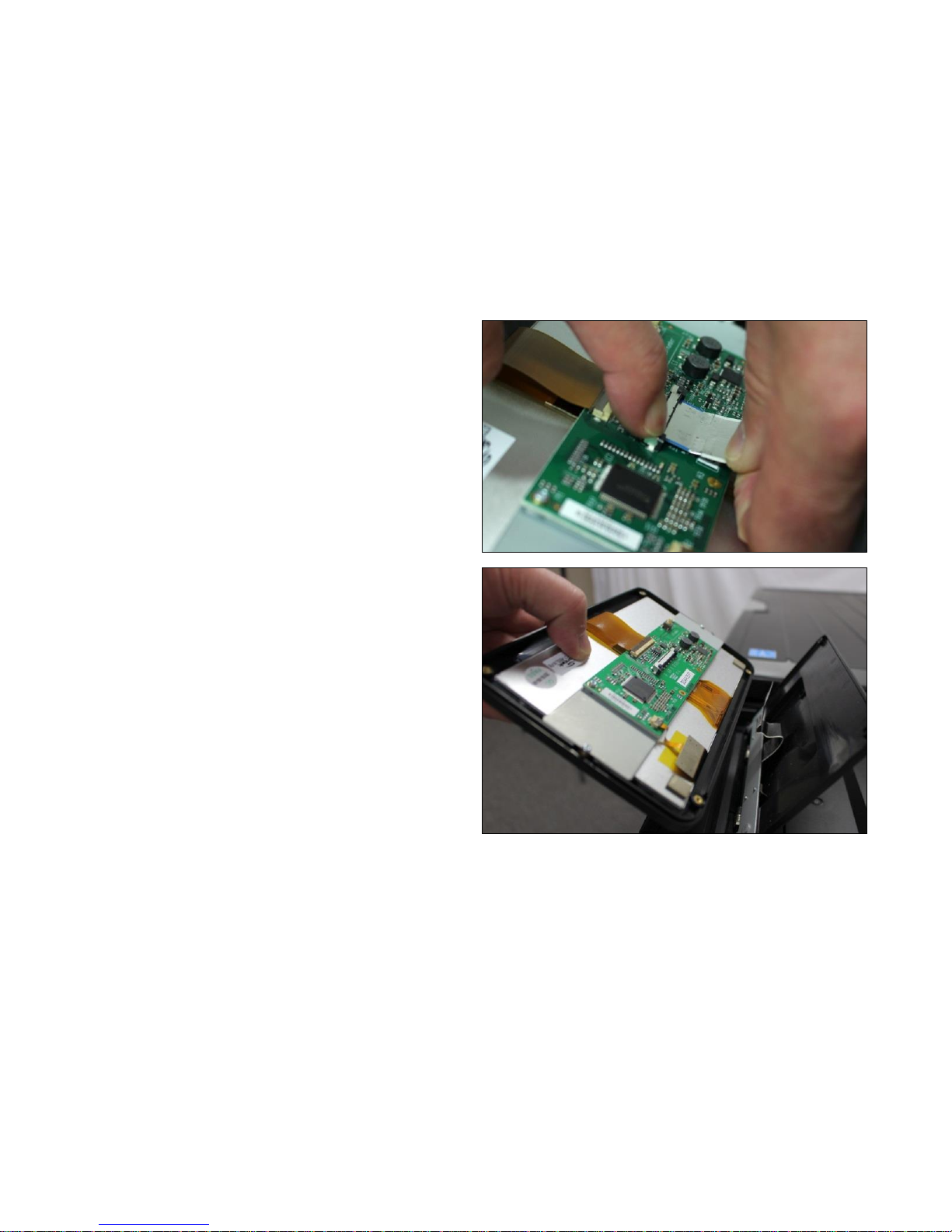
5. While pressing down on both the retaining button of the
connector, gently pull the cable out.
6. Lift the Touchscreen away from the scanner.
Page 43
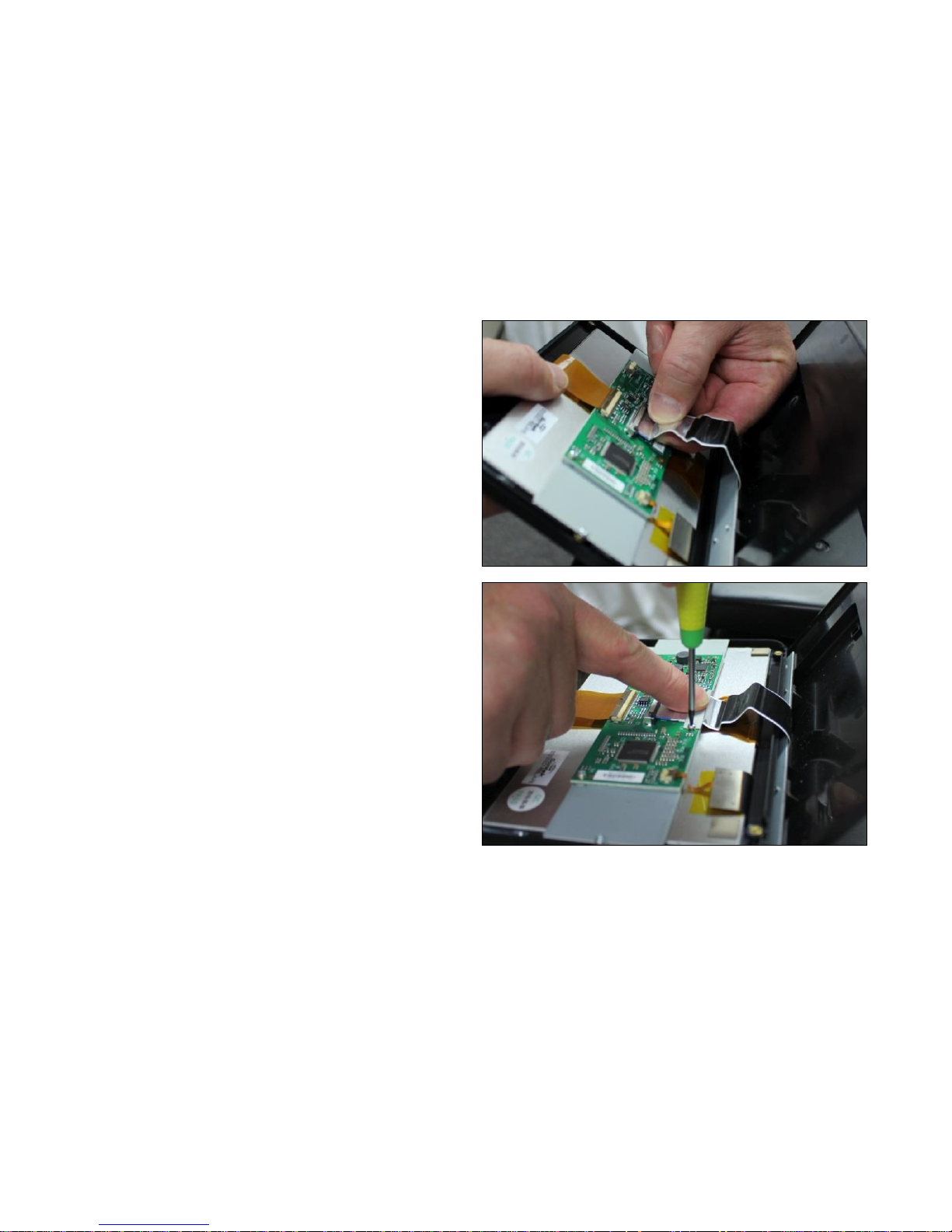
Page | 43
7. To refit, with the silver packing of the cable facing
upwards, press fit the cable into the connector, until both
end latches click in place.
8. Replace the 2 T6 screws to hold the retaining bracket.
Page 44
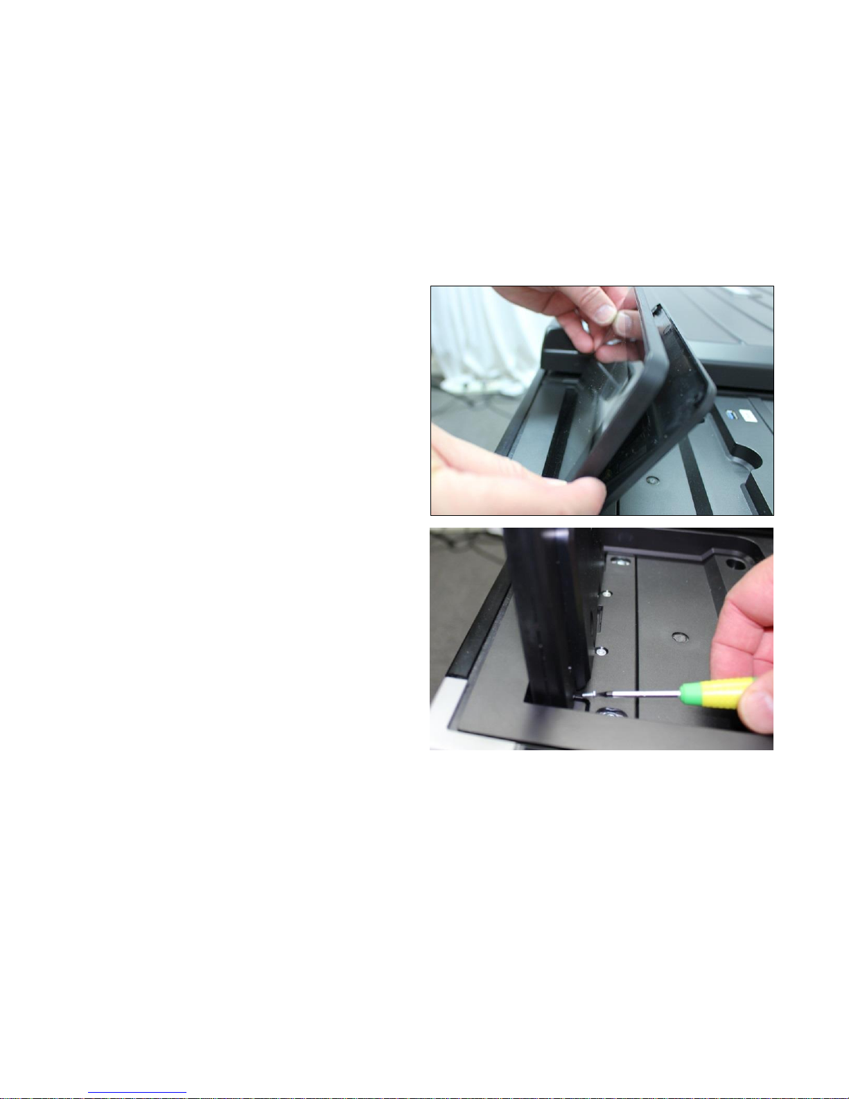
Page | 44
9. Refit the Touchscreen back into the back panel, making
sure not to trap or damage the cable.
10. Refit the 4 T6 screws into the corners of Touchscreen
back cover.
Page 45
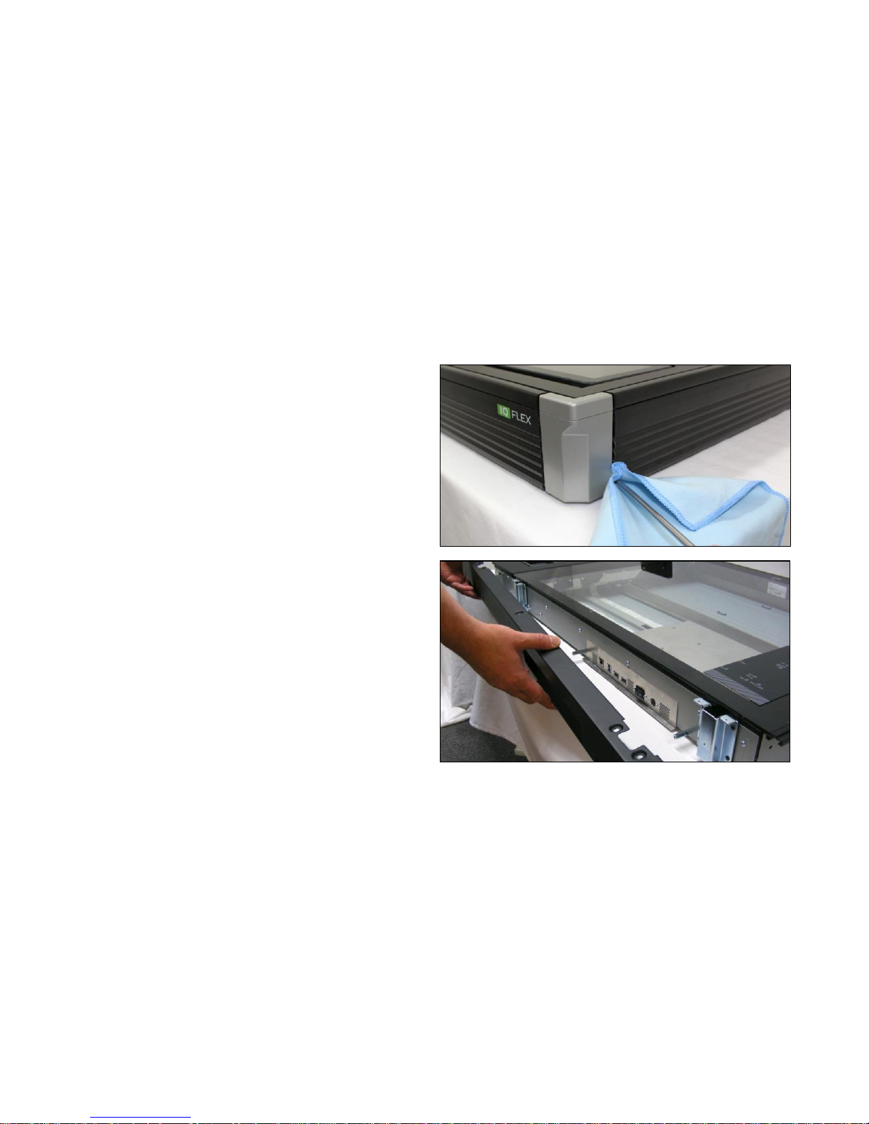
Page | 45
6.7 Top Rear Panel
Tools Required:
T10 Screwdriver
1. Remove the right hand and front covers and panels as
described in ‘
2. Side Covers and Side Panels
3. ’ page 26.
4. Remove the rear panel as described in ‘Rear Panel’
page 33.
Page 46
Page | 46
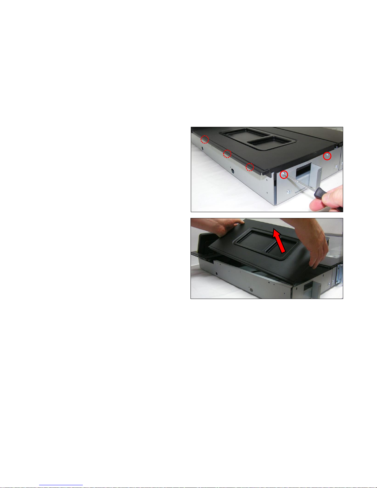
5. Remove the 5 x T10 screws.
6. Lift the Top Rear Panel from out of the scanner.
Page 47
Page | 47
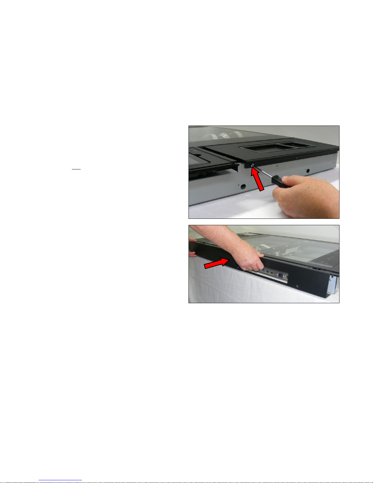
7. Refit the Top Rear Panel into the scanner, making sure
the side edge goes on the outside of the scanner, and
the rear edge goes inside.
8. Refit the rear panel as described in ‘Rear Panel’ page
33.
9. Refit the Side Panels and Side Covers as described in ‘
10. Side Covers and Side Panels
11. ’ page 26.
Page 48
Page | 48
6.8 Glass Plate
Tools Required:
T8 Screwdriver
T10 Screwdriver
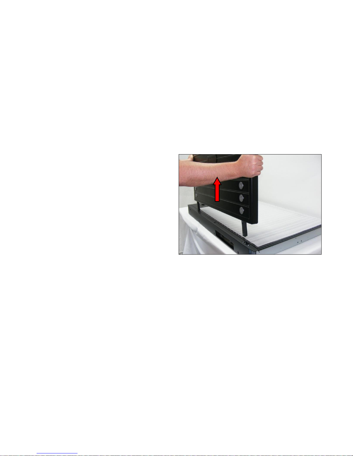
1. Lift the Top Lid Plate out of the recesses in the rear
panel.
Page 49
Page | 49
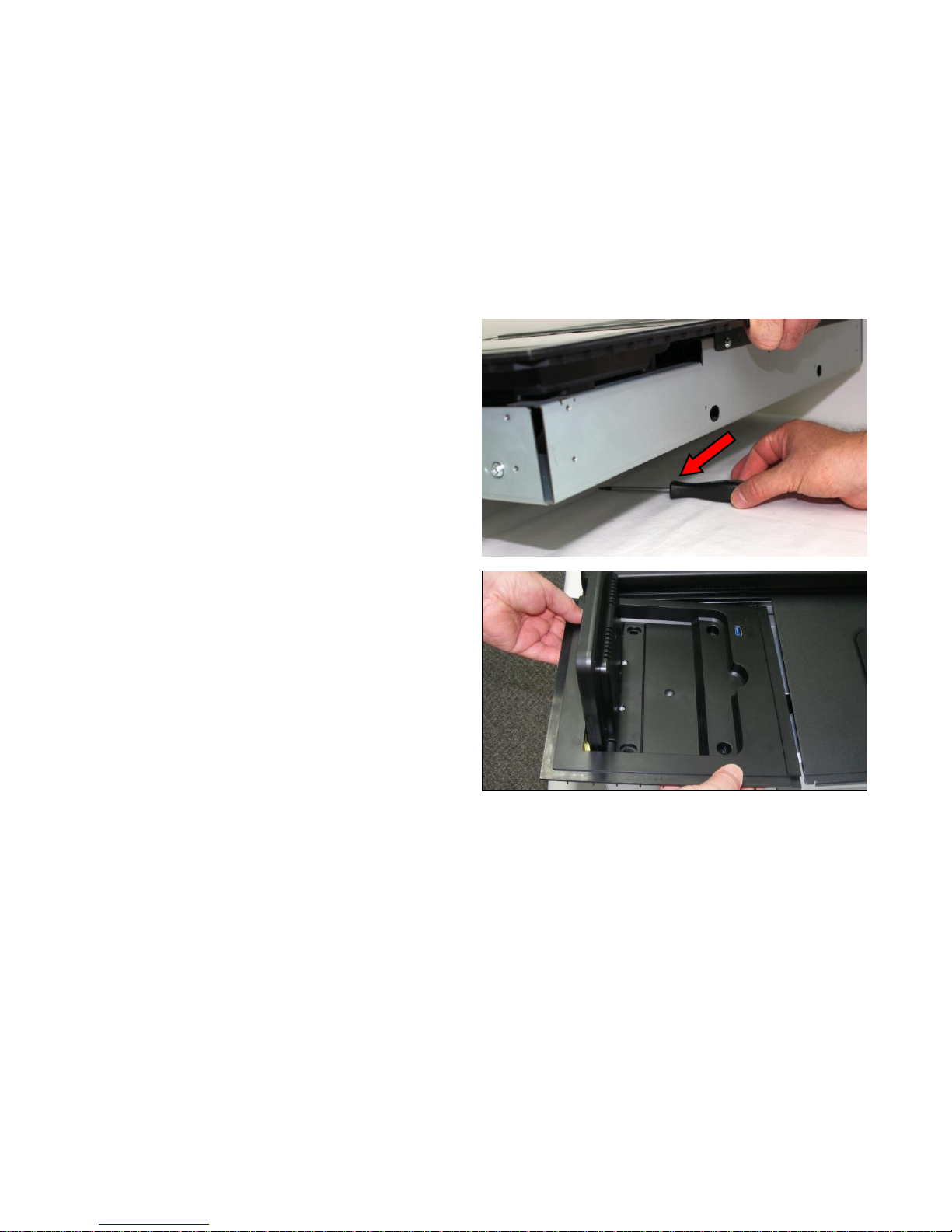
2. Temporarily position a screwdriver, or block, under the
middle of the scanner at the motor end. This means the
scanner is seated on 3 points, and removes any twist in
the chassis when the glass plate is removed.
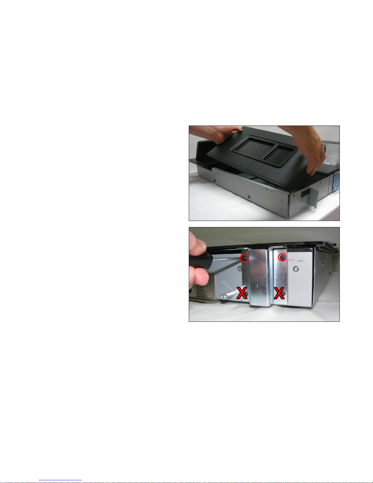
3. Remove the ‘Touchscreen Cover Panel’ as shown on
page 36.
Page 50
Page | 50
4. Remove the ‘Top Rear Panel’ as shown on pages 45.
5. Remove the 2 x T8 screw from the tops of both hinge
brackets.
Page 51
Page | 51
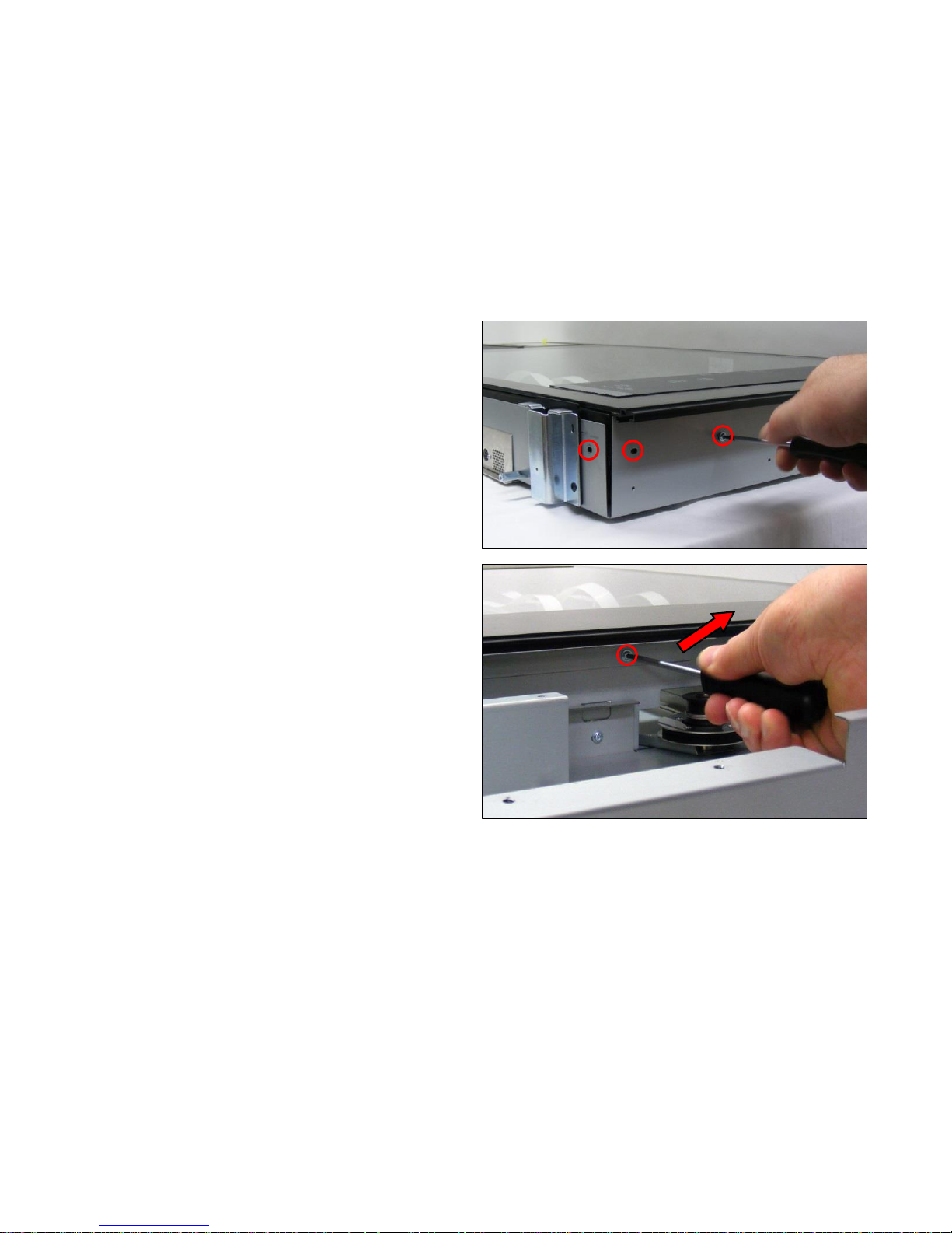
6. Remove the T10 screws from round the edge of the
glass plate.
7. Remove the 2 x T10 screws holding both the support
brackets, and remove the brackets.
Page 52
Page | 52
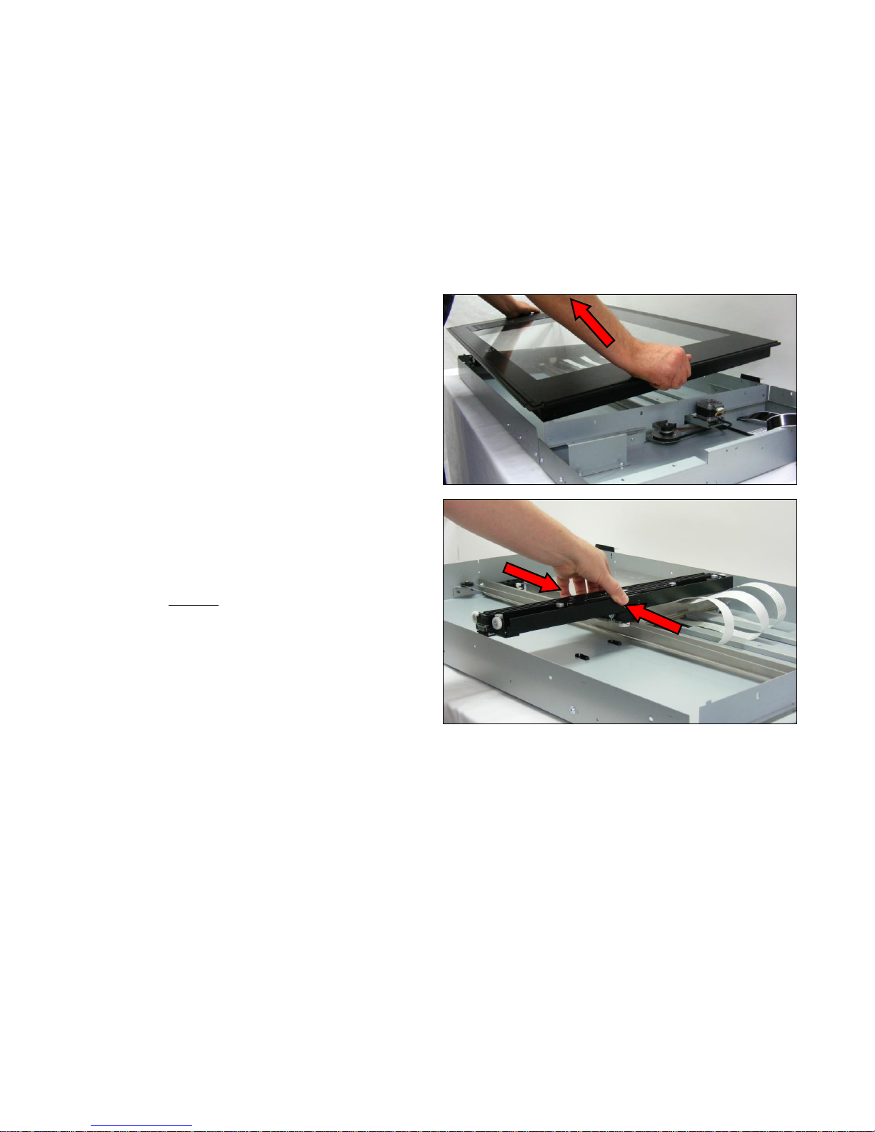
8. Carefully lift the glass up and out of the scanner.
9. To replace the glass plate, make sure the CIS Carriage
is in the middle of the scanner unit to make positioning
the glass plate easier.
Page 53
Page | 53
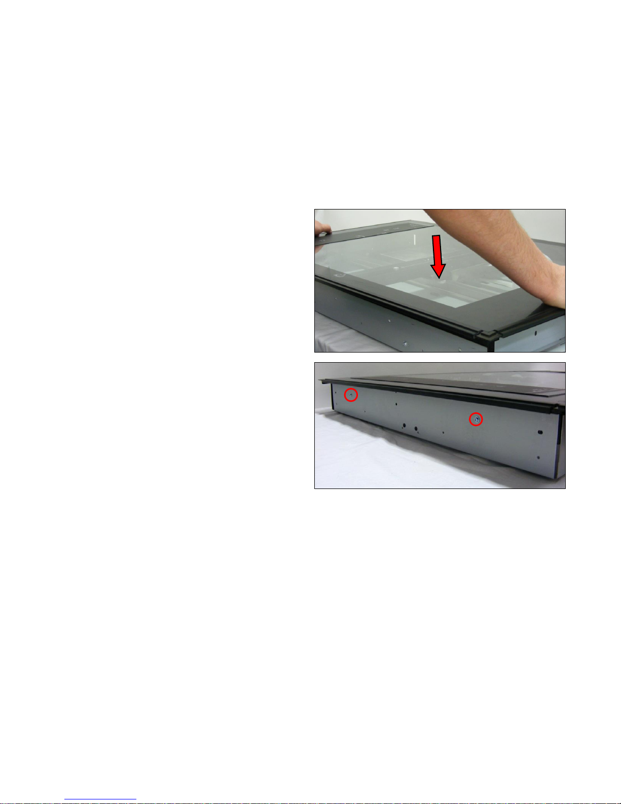
10. Position the Glass Plate into the scanner chassis, over
the CIS Carriage, with the measurement markings at the
left hand end of the scanner. Make sure the glass is fully
down against the chassis.
11. Replace 2 of the T10 screws in the end of the scanner
chassis.
Page 54
Page | 54
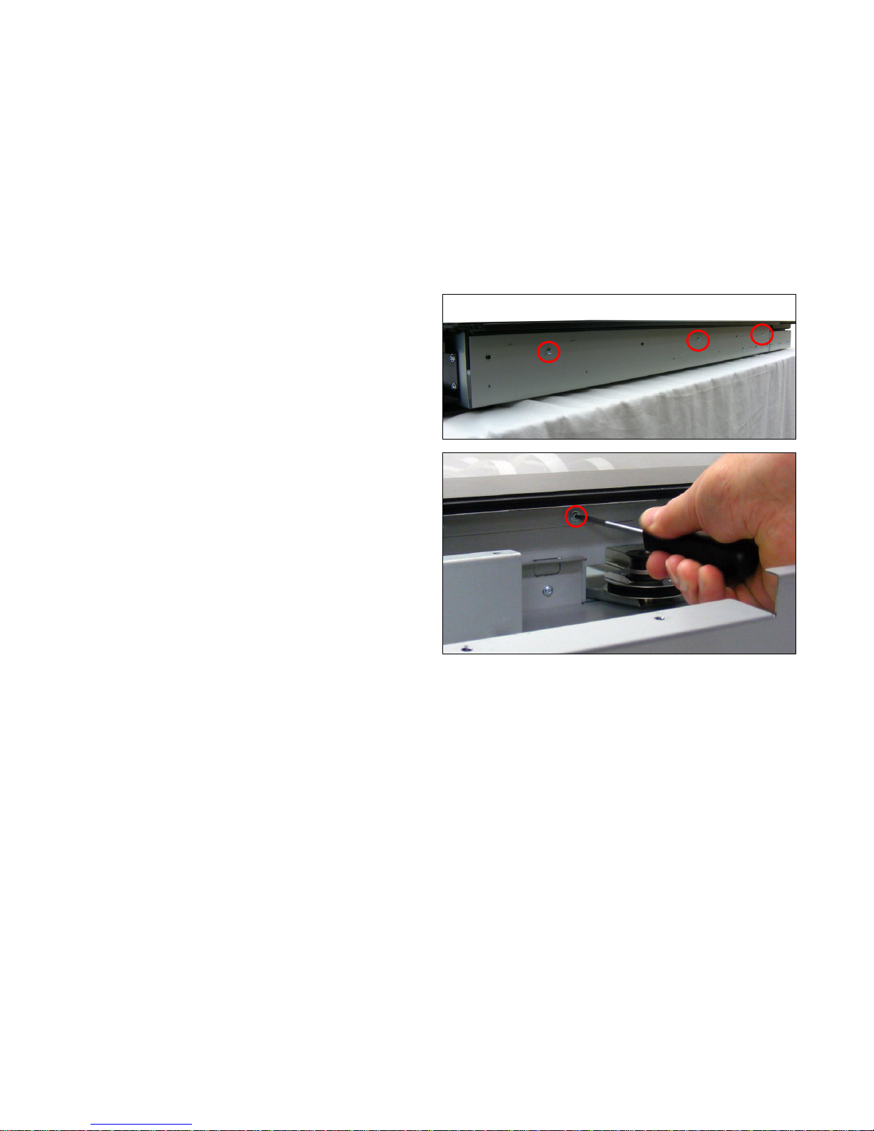
12. Replace 3 of the T10 screws in the front of the scanner
chassis.
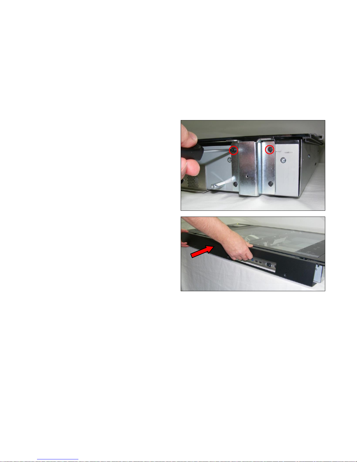
13. Replace both of the support brackets at the right hand
end of the scanner.
Page 55
Page | 55
14. Refit the 2 x T8 screws into the tops of both hinge
brackets.
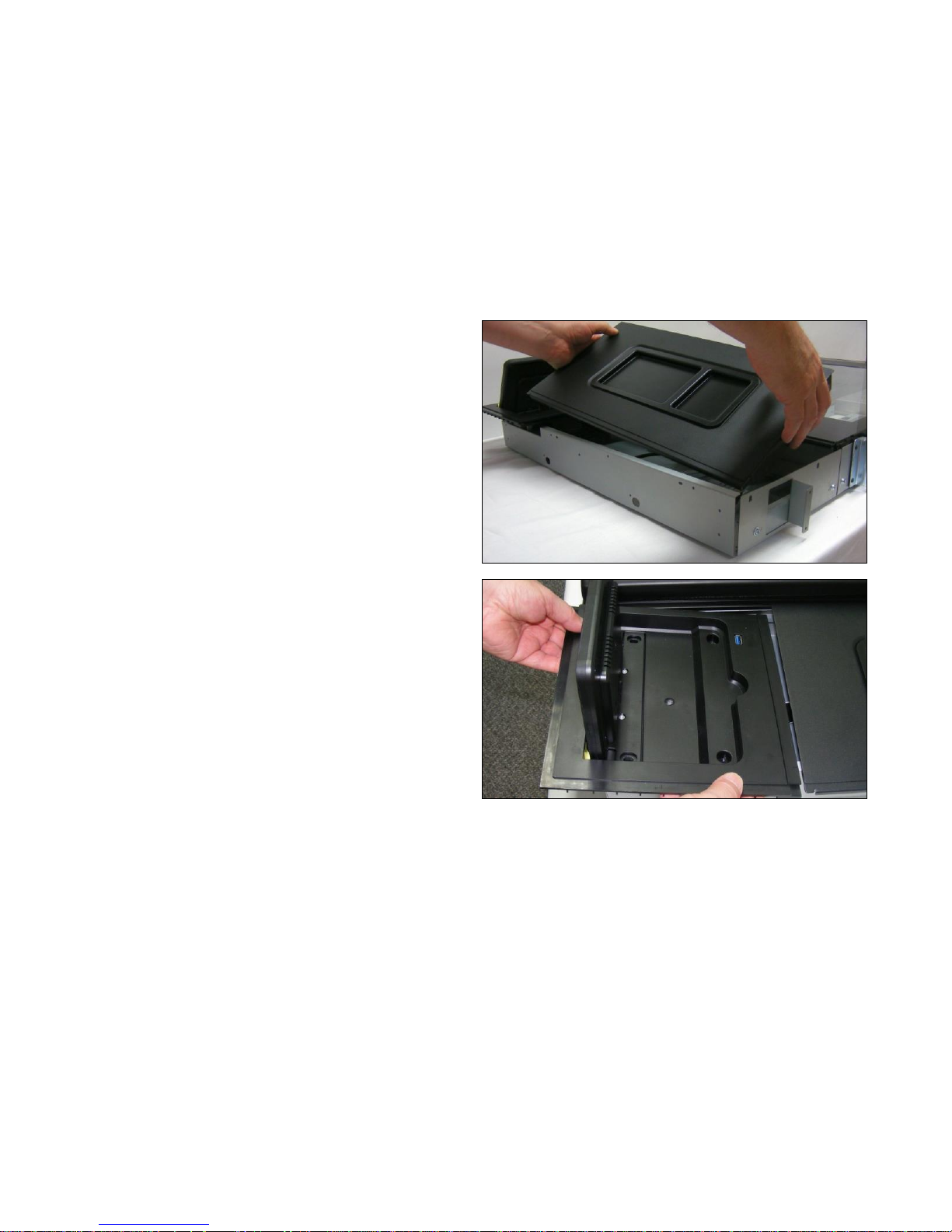
15. Refit the ‘Rear Panel’ as described on page 33.
Page 56
Page | 56
16. Refit the ‘Top Rear Panel’ as shown on pages 45.
17. Refit the ‘Touchscreen Cover Panel’ as shown on page
36.
Page 57
Page | 57
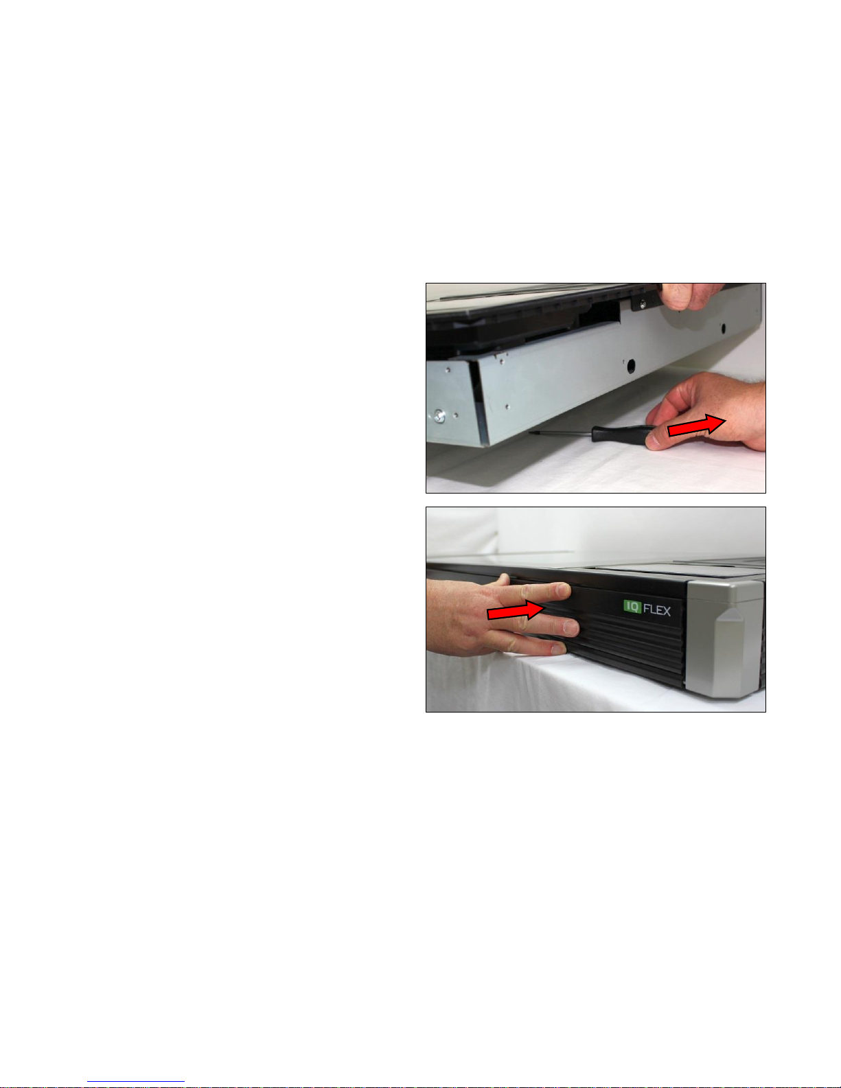
18. Remove the screwdriver or block from under the scanner
chassis.
19. Refit all the ‘
20. Side Covers and Side Panels
21. ’ as shown on page 26.
Page 58
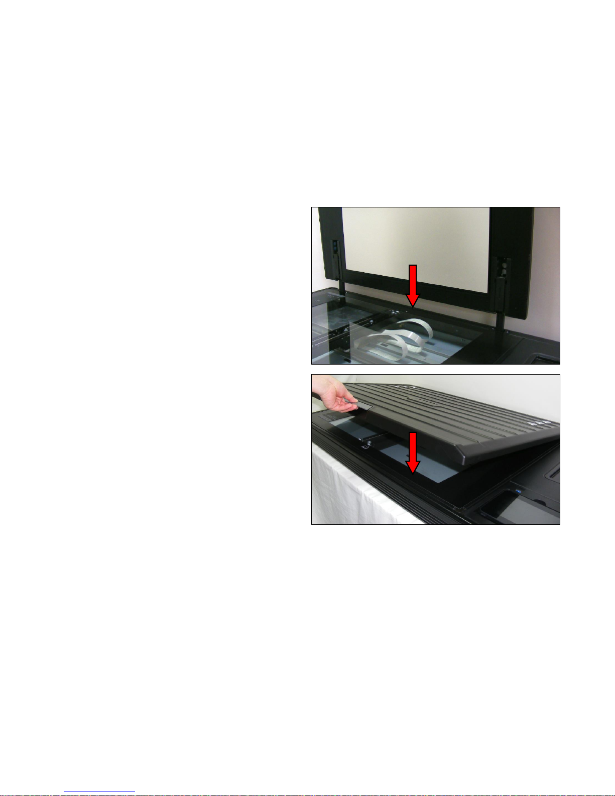
Page | 58
22. Slide the Top Lid Plate brackets into the cutouts of the
rear panel.
23. Close down the Top Lid Cover.
Page 59
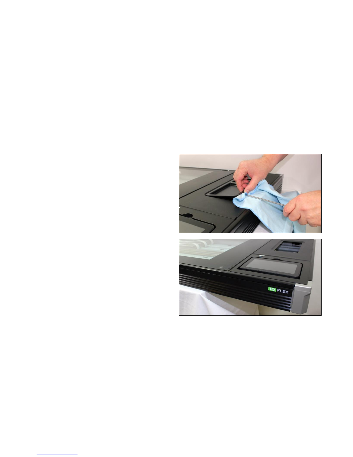
Page | 59
6.9 Motor Unit
Tools Required:
T20 Screwdriver.
Large Flat Screwdriver.
1. Use a flat screwdriver and soft cloth to remove the tray
from the Top Rear Panel.
2. Carefully over-hang the IQ FLEX over a table edge,
leaving the majority of the weight on the table, so as to
access the motor mount screws underneath the unit.
Page 60
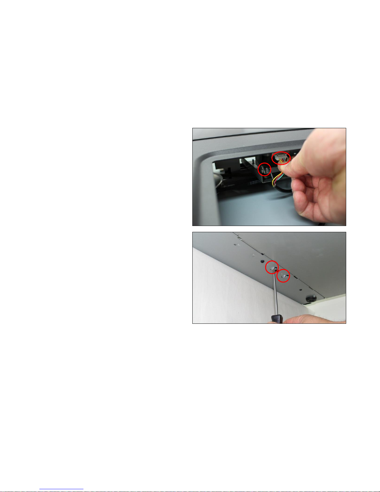
Page | 60
3. Disconnect the earth cable and the control cable from
the Motor.
4. While holding the Motor Unit, remove the 2 x T20 screws
holding the Motor mount in place.
Page 61
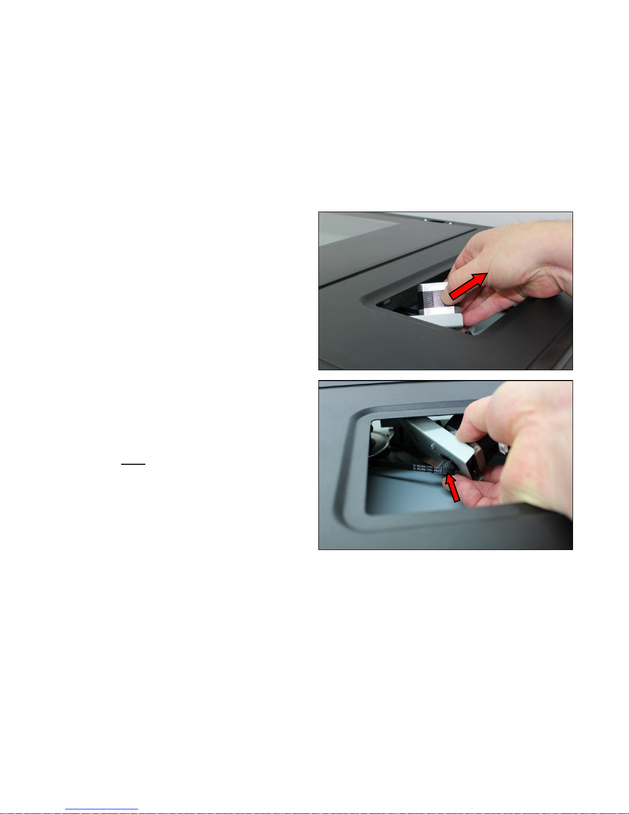
Page | 61
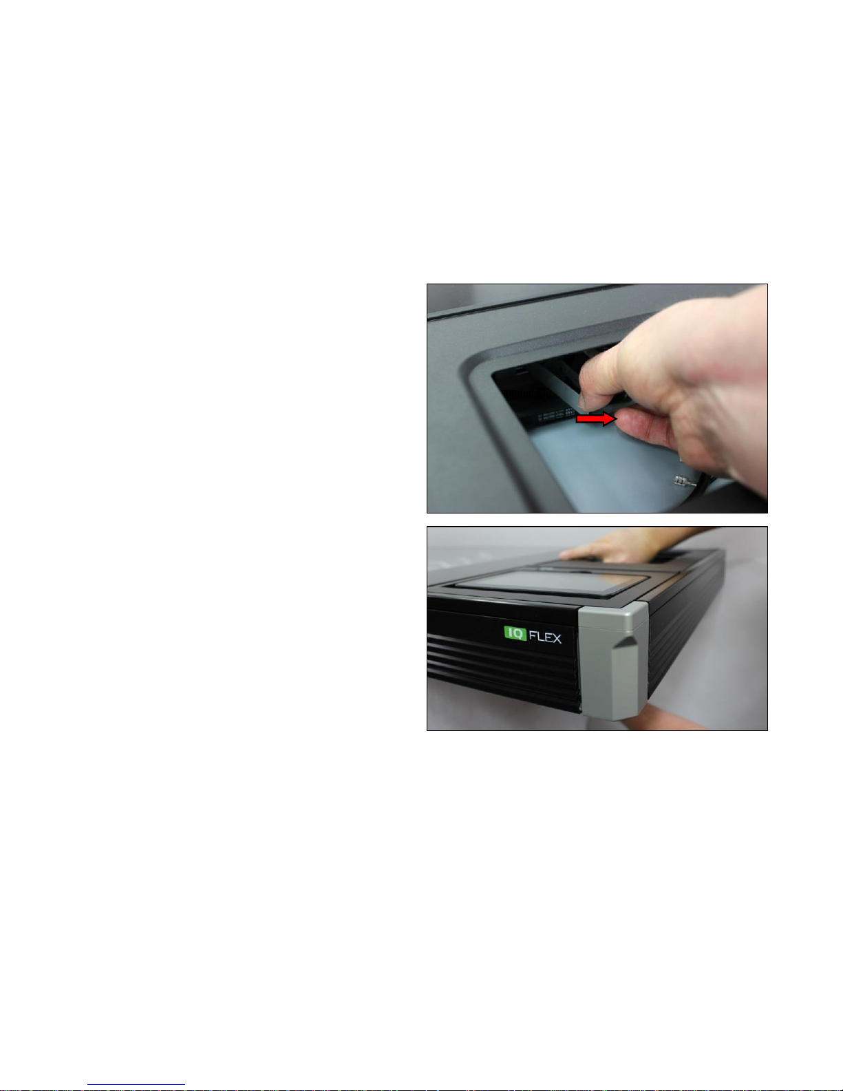
5. Release from the timing belt and remove the Motor.
6. To refit the Motor, position the Timing Belt around the
pulley, and hold in place while refitting the Motor.
Page 62
Page | 62
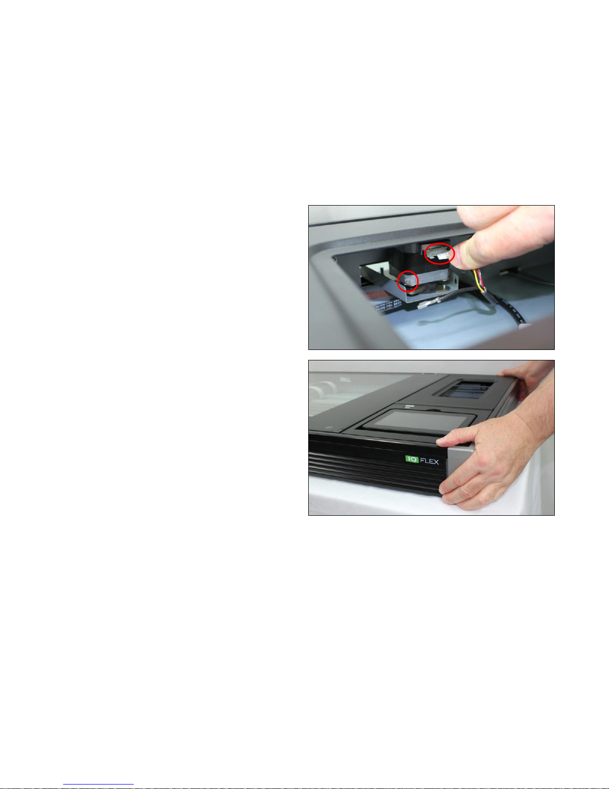
7. Reposition the Motor, and pull across to hold the timing
belt in position while replacing the 2 x T20 screws from
underneath.
8. Tighten the 2 x T20 screws while holding in position.
Page 63
Page | 63
9. Reconnect the earth cable and control cable to the
Motor.
10. Push the IQ FLEX back fully back into its correct
position.
Page 64
Page | 64
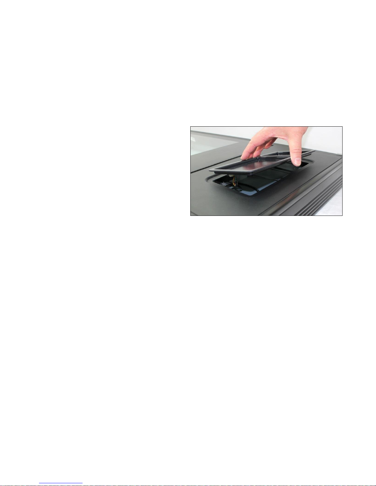
11. Replace the Top Rear Panel tray. The tape should still
stick properly, if not, replace with new double-sided tape.
Page 65
Page | 65
6.10 Carriage Home Sensor
Tools Required:
5.5mm Nut-driver
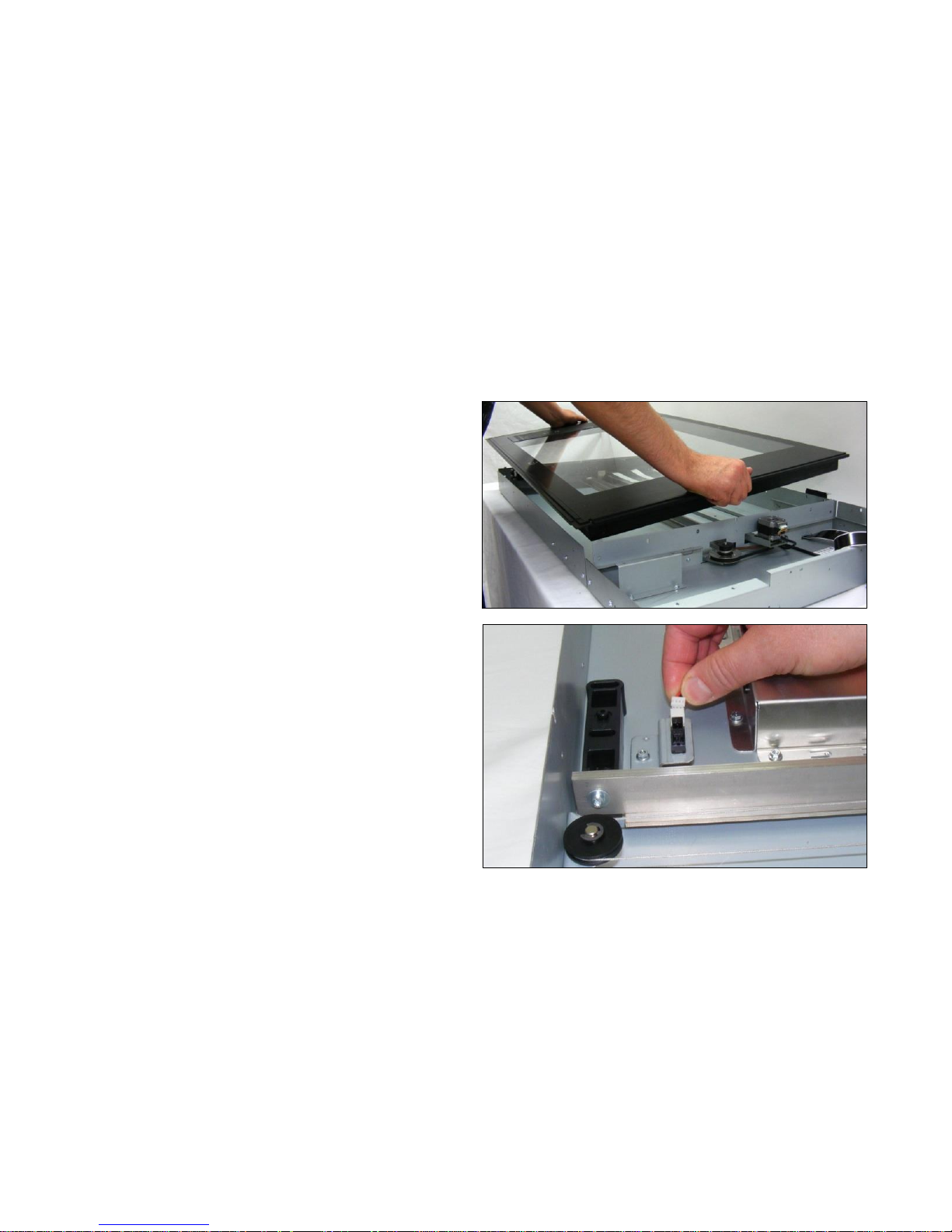
1. Remove the Glass Plate as shown on page 48.
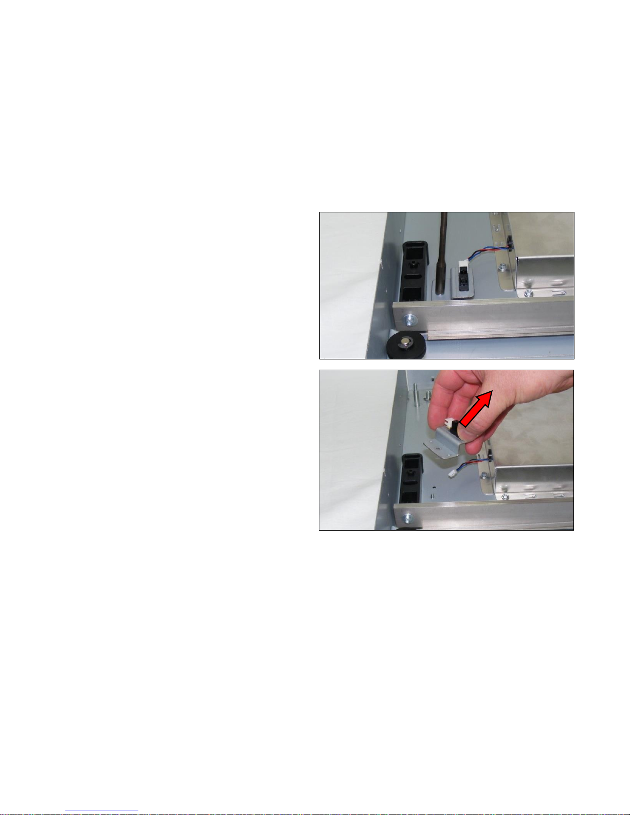
2. Disconnect the sensor cable from the Sensor.
Page 66
Page | 66
3. Remove the M3 nut from the Sensor Bracket.
4. Remove the Sensor Bracket.
Page 67
Page | 67
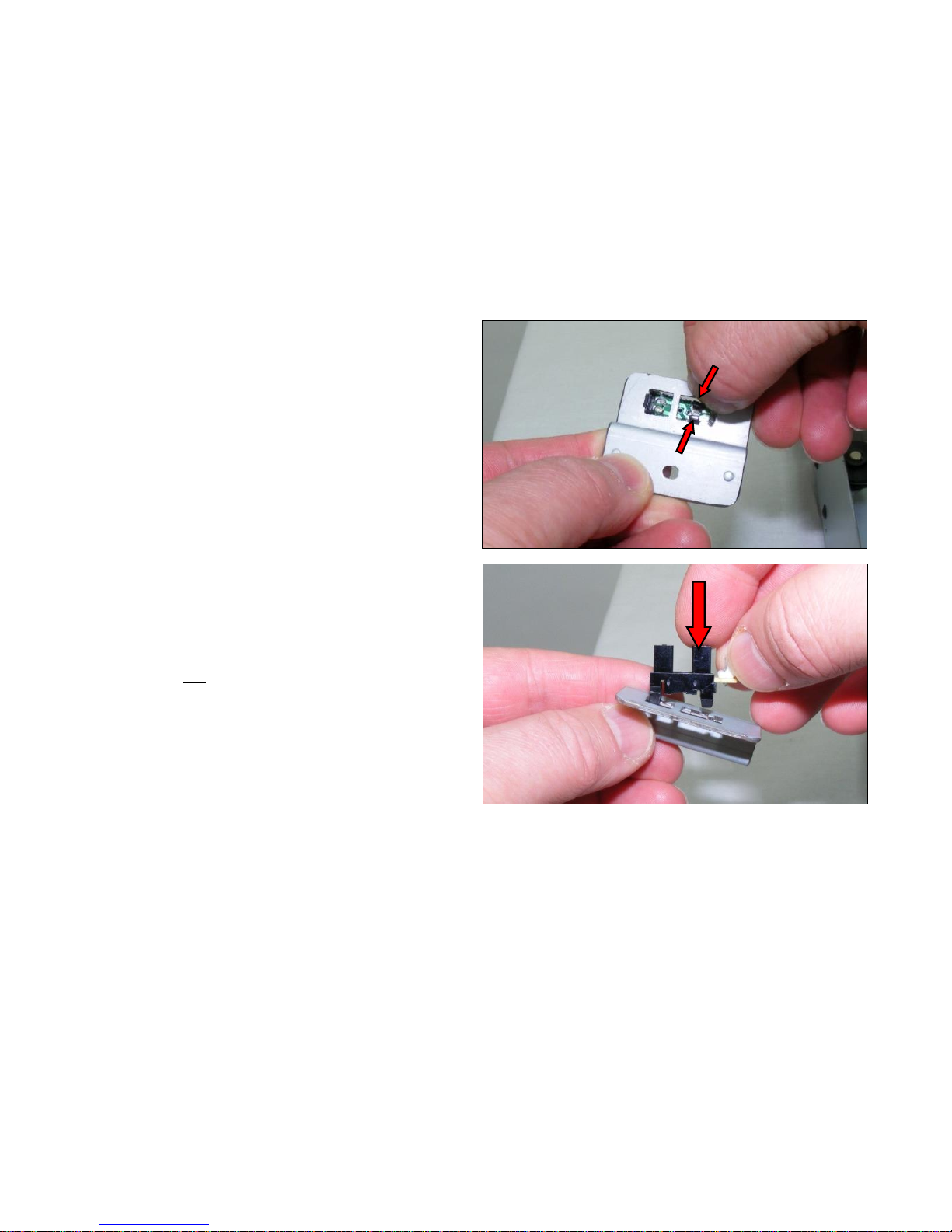
5. Remove the Sensor by pressing gently on the tabs to
release from the bracket.
6. Refit the Sensor by pressing gently into the sensor
bracket.
Page 68
Page | 68
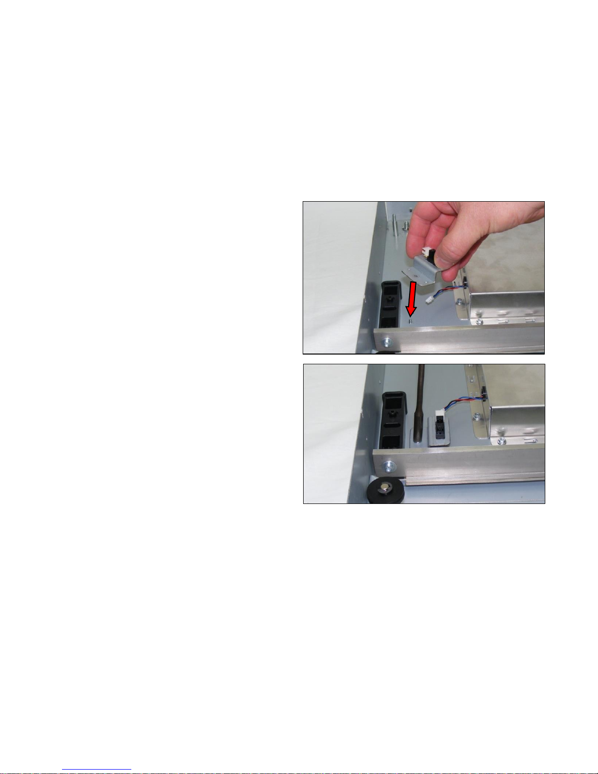
7. Refit the Sensor Bracket over the M3 threaded post.
8. Refit the M3 nut to hold the Sensor Bracket.
Page 69
Page | 69
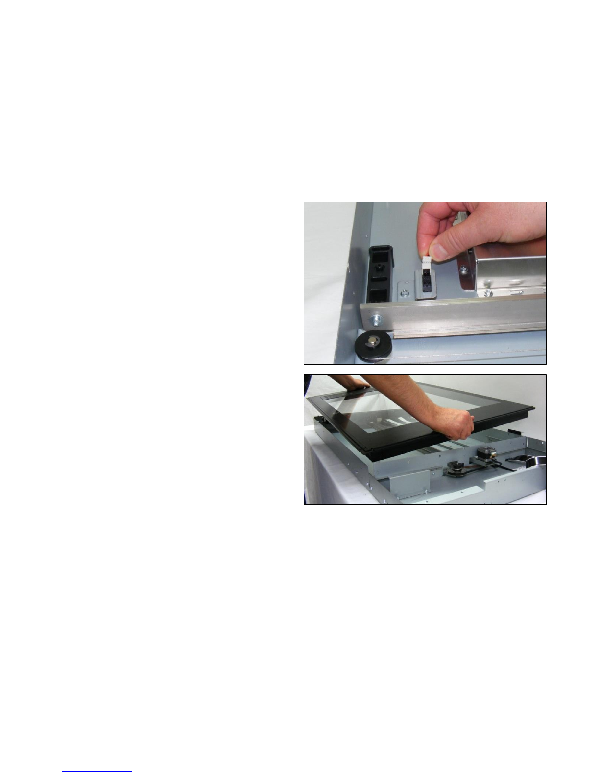
9. Reconnect the sensor cable to the Sensor.
10. Refit the Glass Plate as shown on page 48.
Page 70
Page | 70
6.11 CIS Carriage
Tools Required:
T10 Screwdriver
5.5mm Nutdriver (for M4 nuts)
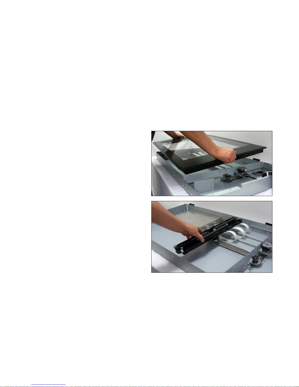
1. Remove the Glass Plate as shown on page 48.
2. Move the carriage across to about the center for easy
removing of the pulley wire.
Page 71
Page | 71
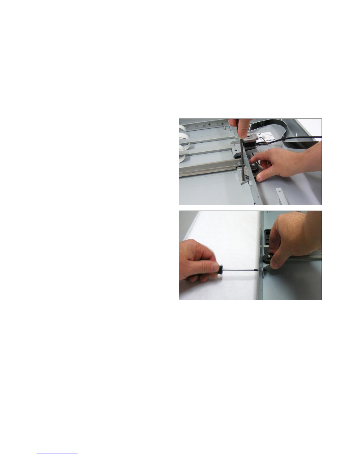
3. Loosen the 2 x M4 nuts (but do not remove) and allow
the pulley bracket to move, loosening the pulley wire.
4. Loosen the 2 x T8 screws (but do not remove) and allow
the pulley wire to loosen further.
Page 72
Page | 72
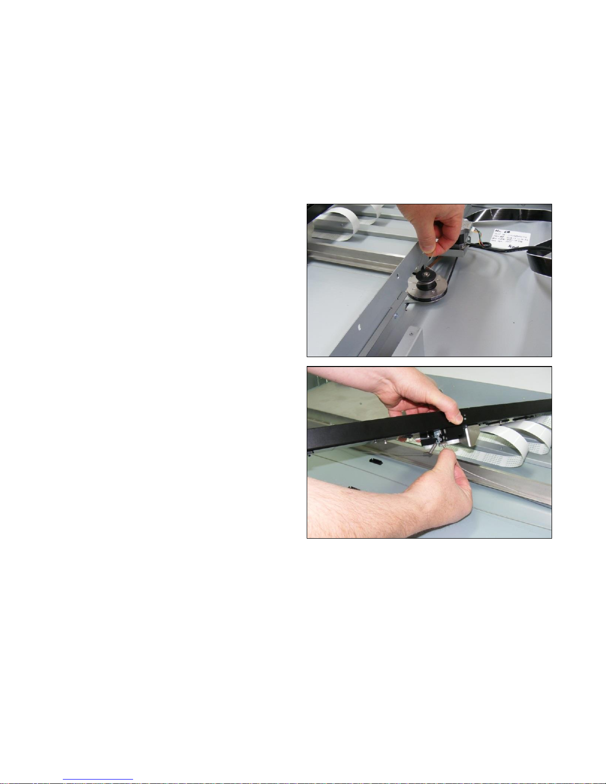
5. Release the pulley wire from around the pulley.
6. Gently lift the CIS Carriage off the runner, and release
the two ends of the pulley wire.
Page 73
Page | 73
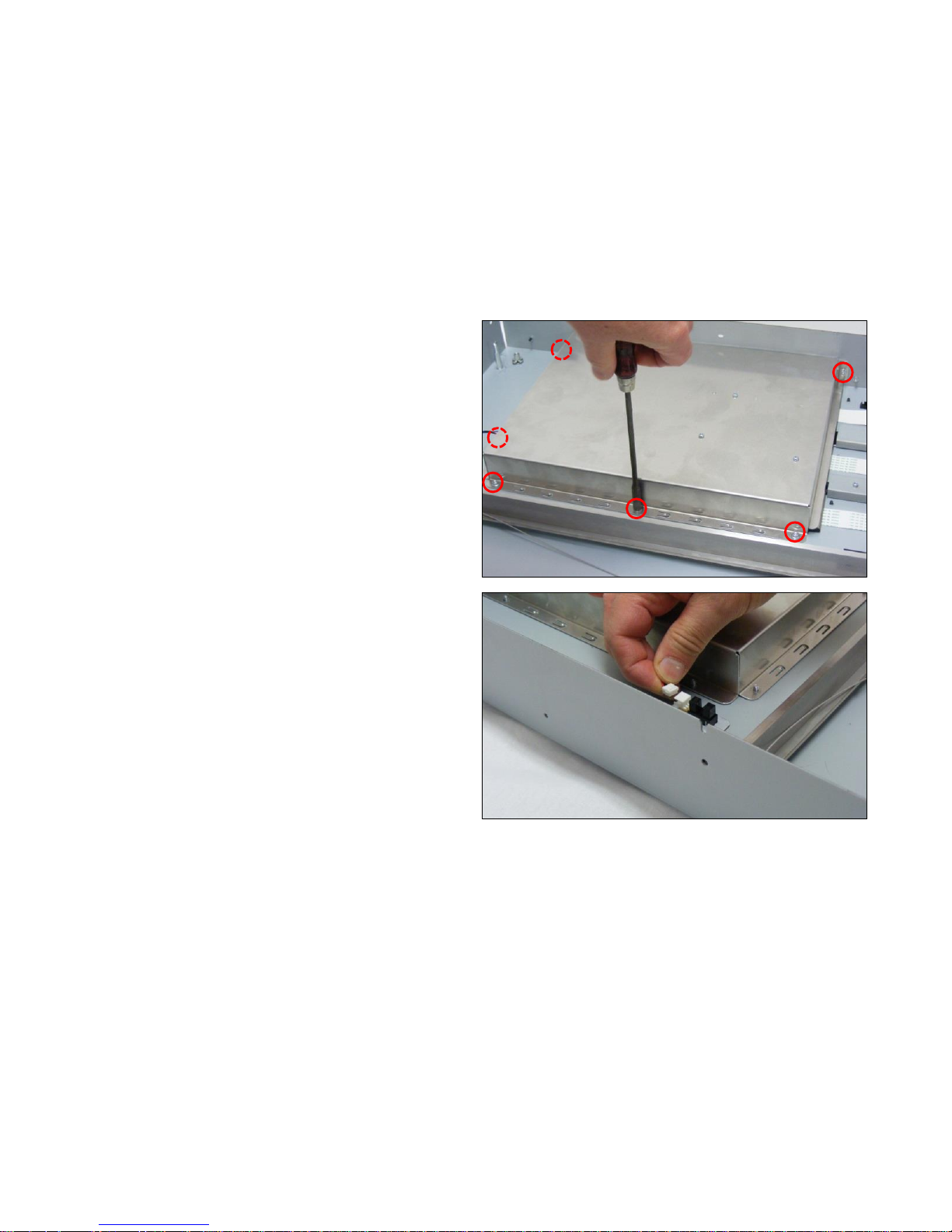
7. Remove the 6 x M4 nuts holding the Controller Board
cover to the chassis.
8. Disconnect the sensor cable.
Page 74
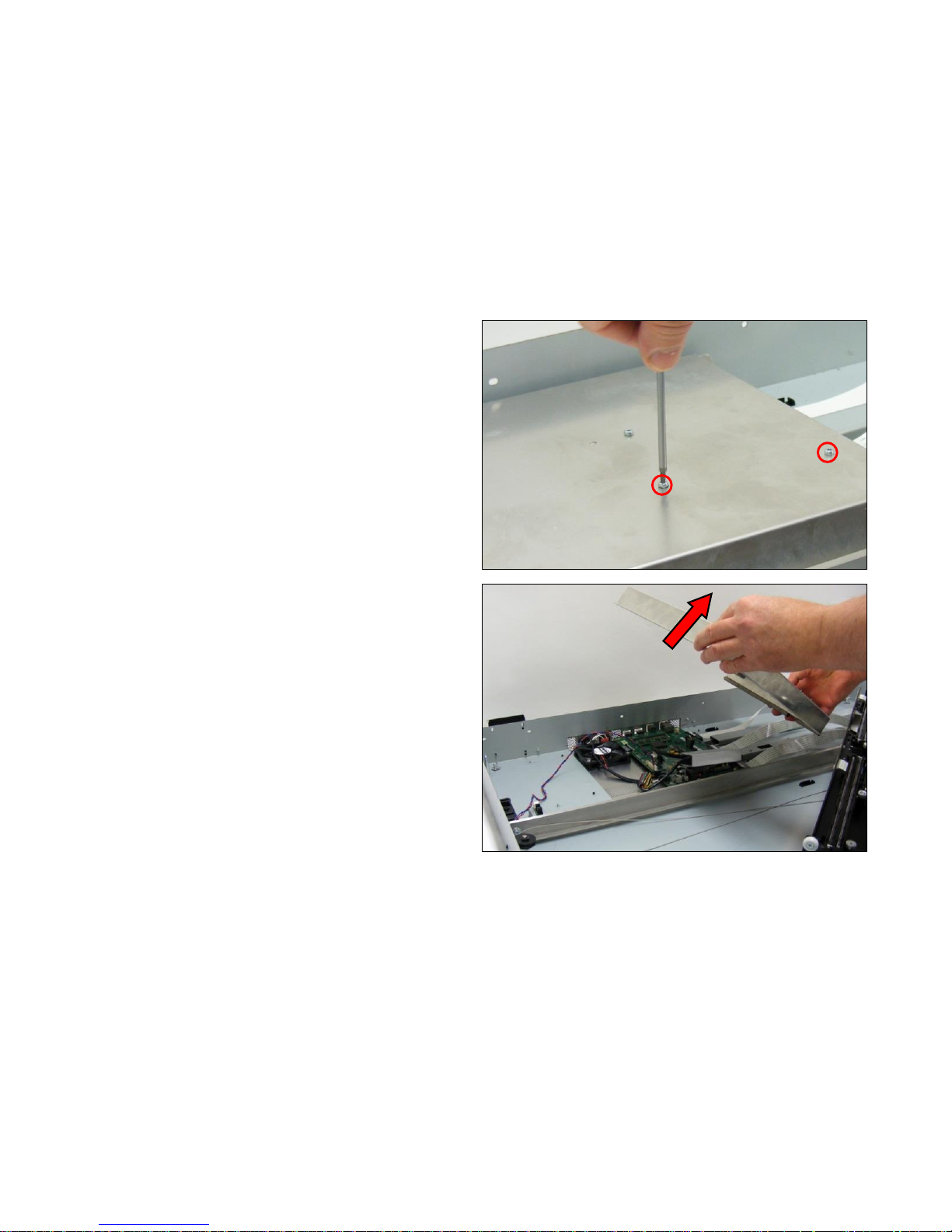
Page | 74
9. Remove the 2 x T20 screws on the top of the Controller
board cover to release the cable bracket from under the
cover.
10. Gently remove the Controller Board cover, making sure
not to catch or damage any of the cables.
Page 75
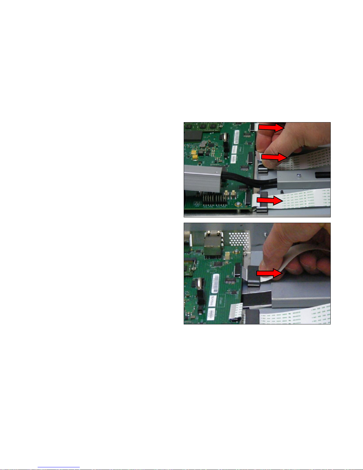
Page | 75
11. Gently pull each cable out of the Controller Board
connectors.
12. Gently pull each cable out of the each ferrite.
Page 76
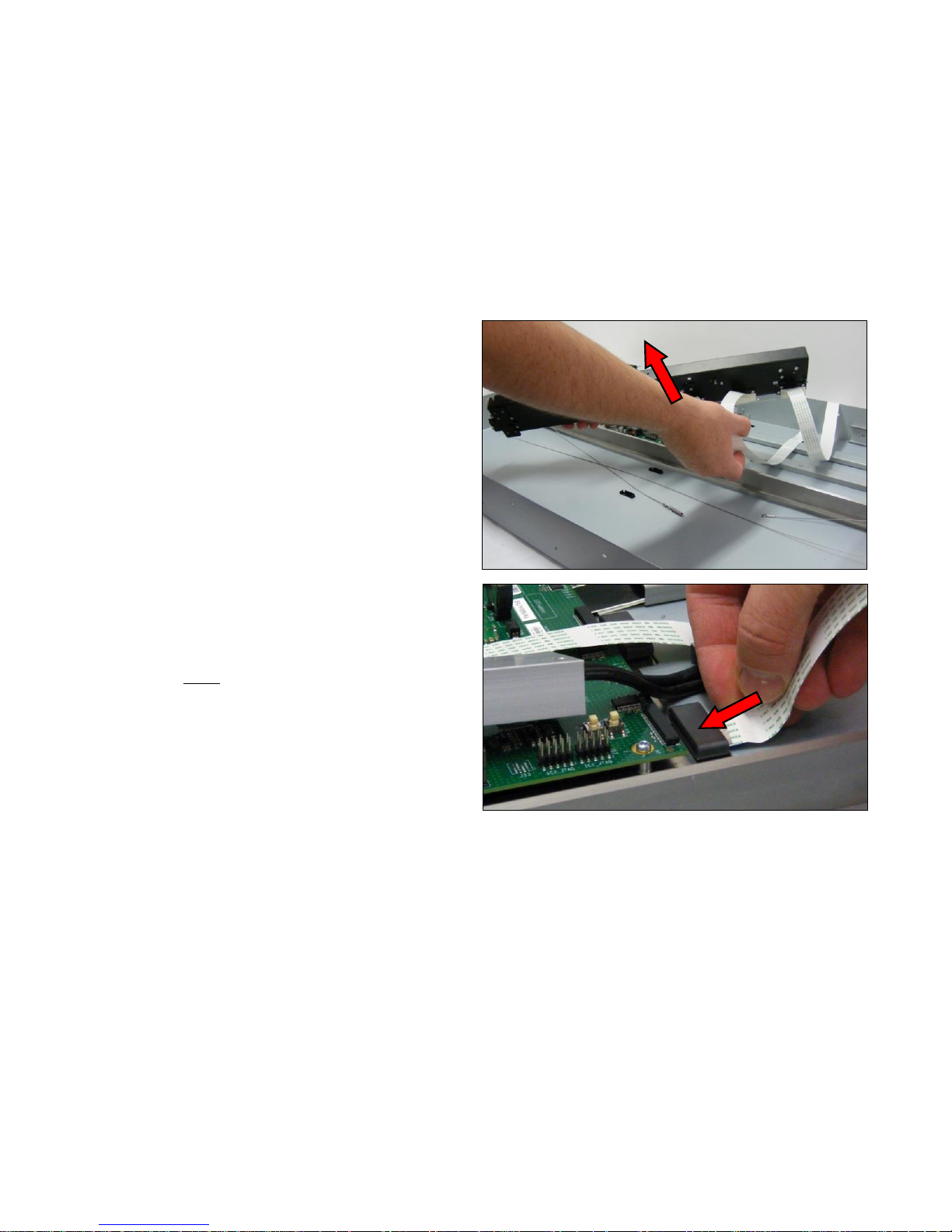
Page | 76
13. Lift the CIS Carriage and cables out of the scanner.
14. To refit, push each ribbon cable from the CIS Carriage
through their respective ferrite on the chassis, making
sure not to damage the cable while maneuvering to the
board.
Page 77
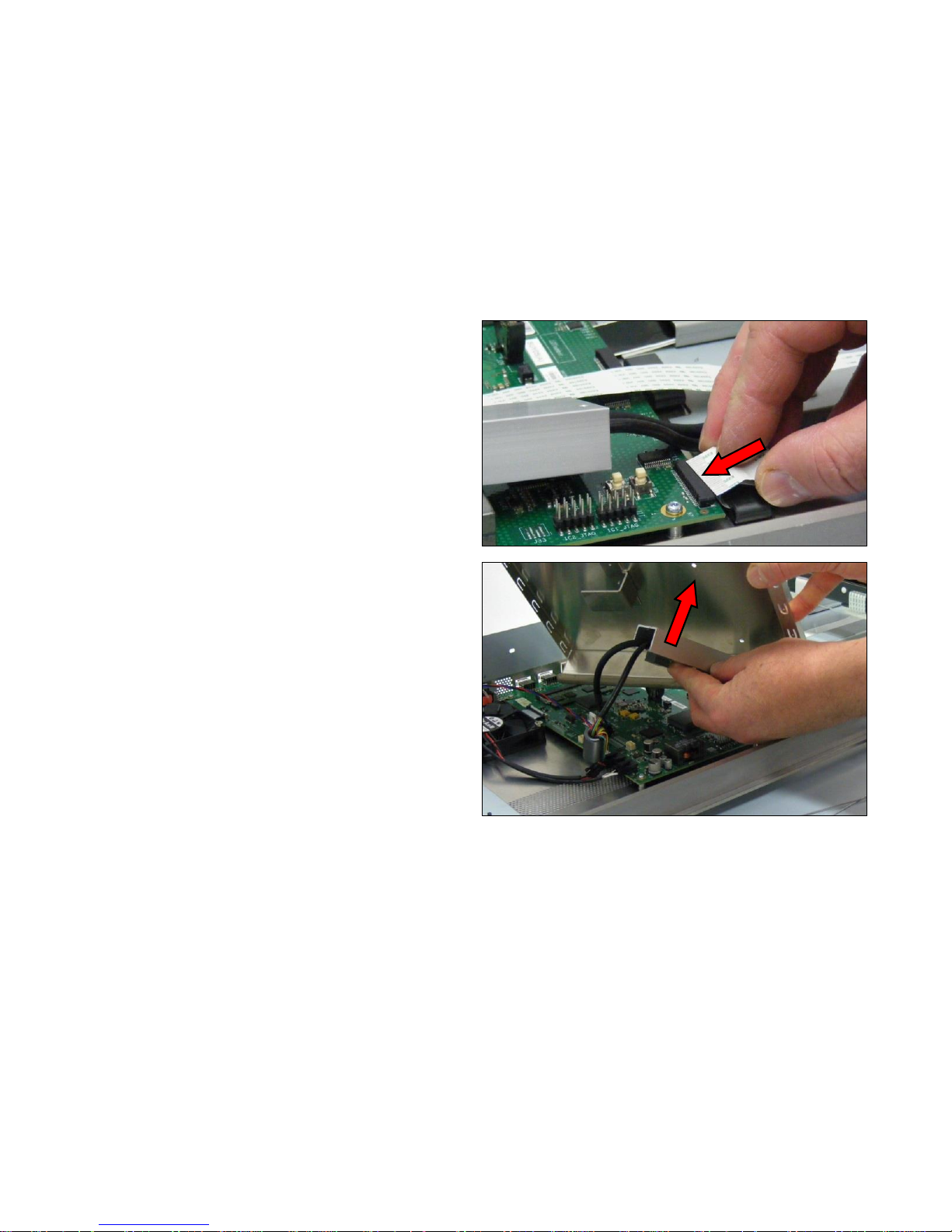
Page | 77
15. Gently push each ribbon cable into the connectors,
taking great care not to damage the ribbon cable.
16. Position the cable bracket against the Controller Board
cover and refit the 2 x T20 screws. Take care not to
damage the cables.
Page 78
Page | 78
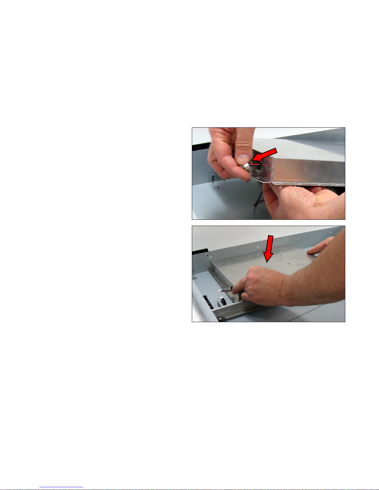
17. Push the sensor cable through the hole at the end of the
Controller Board cover.
18. Re-position the Controller Board Cover and replace the
6 x M4 nuts.
Page 79
Page | 79
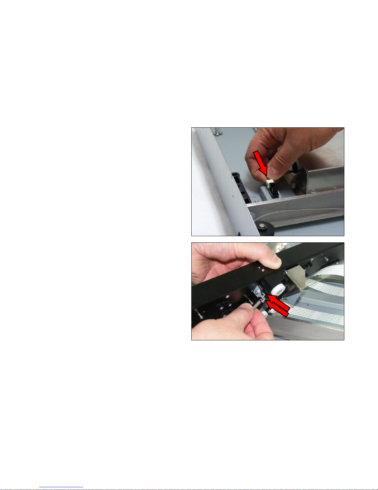
19. Re-connect the cable to the sensor.
20. Re-connect both ends of the pulley cable to the CIS
Carriage.
Page 80
Page | 80
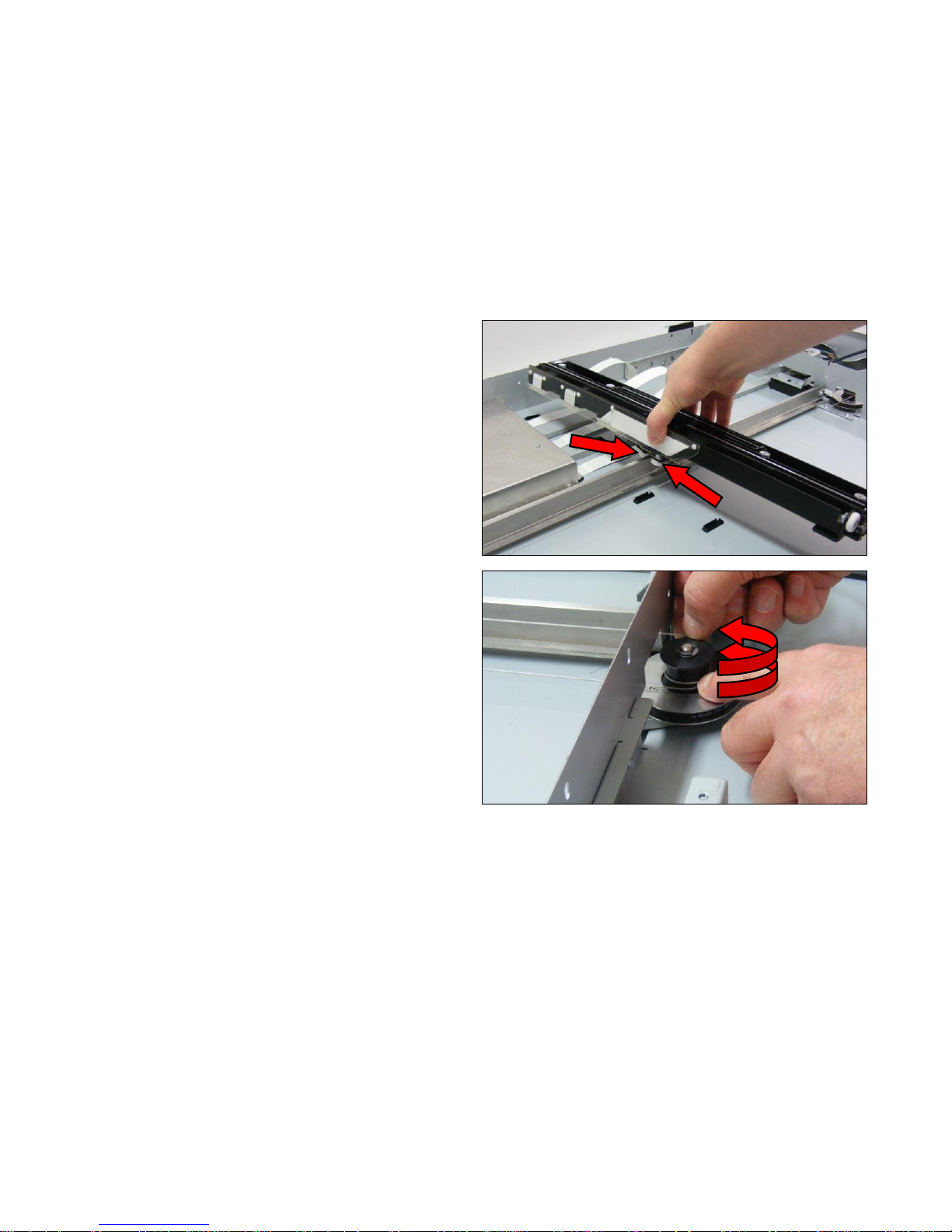
21. To refit the CIS Carriage, position on to the runner,
making sure the support wheels are either side of the
runner.
22. Wrap the pulley cable twice around the drive pulley.
Page 81
Page | 81
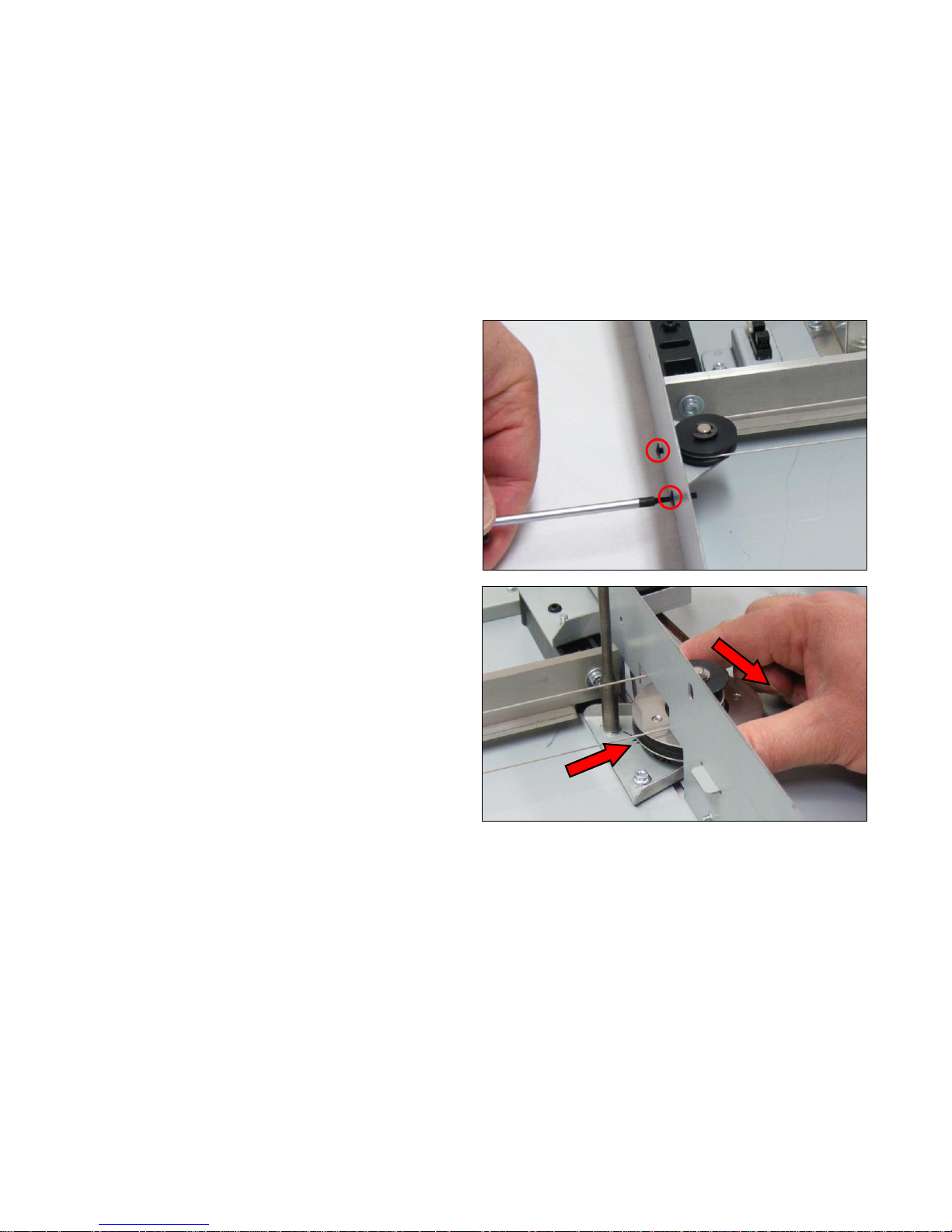
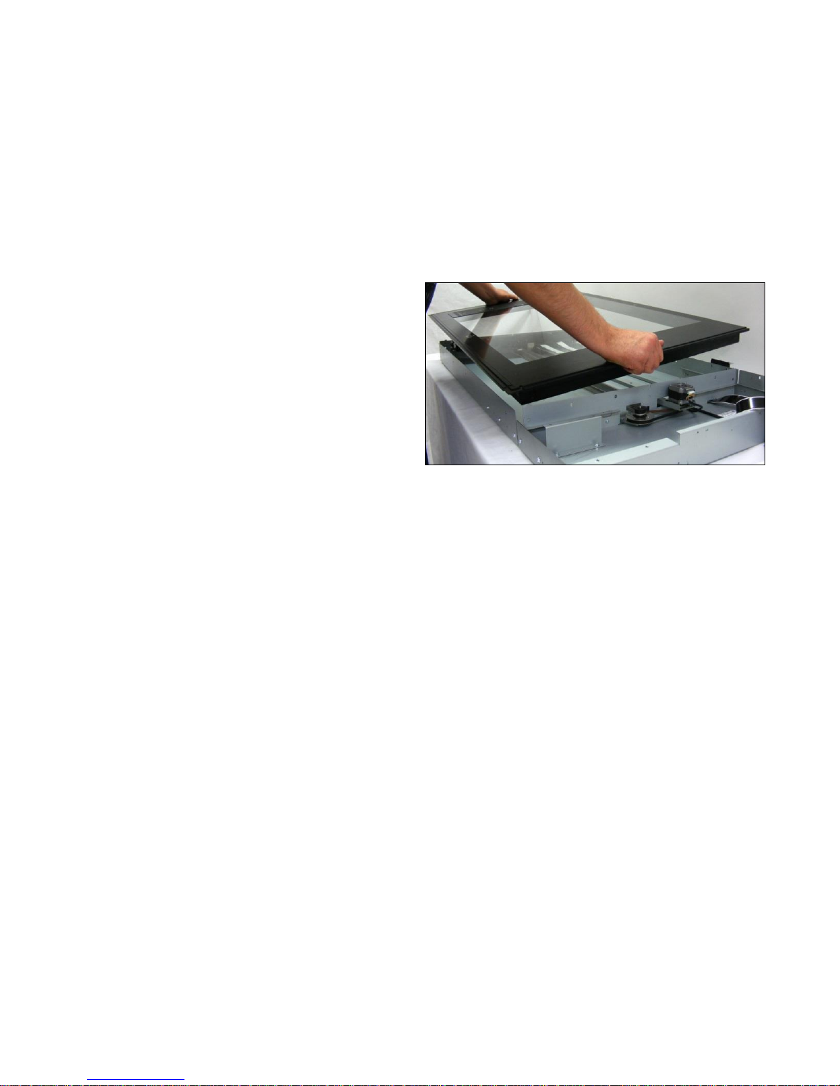
23. Tighten the 2 x T8 screws to tension the pulley cable.
24. Tighten the 2 x M4 nuts on the pulley bracket, while
pulling the bracket to ensure tension on the pulley cable
and the timing belt.
Page 82
Page | 82
25. Refit the Glass Plate as shown on page 48.
Page 83
Page | 83
6.12 Controller Board Panel
Tools Required:
T10 Screwdriver
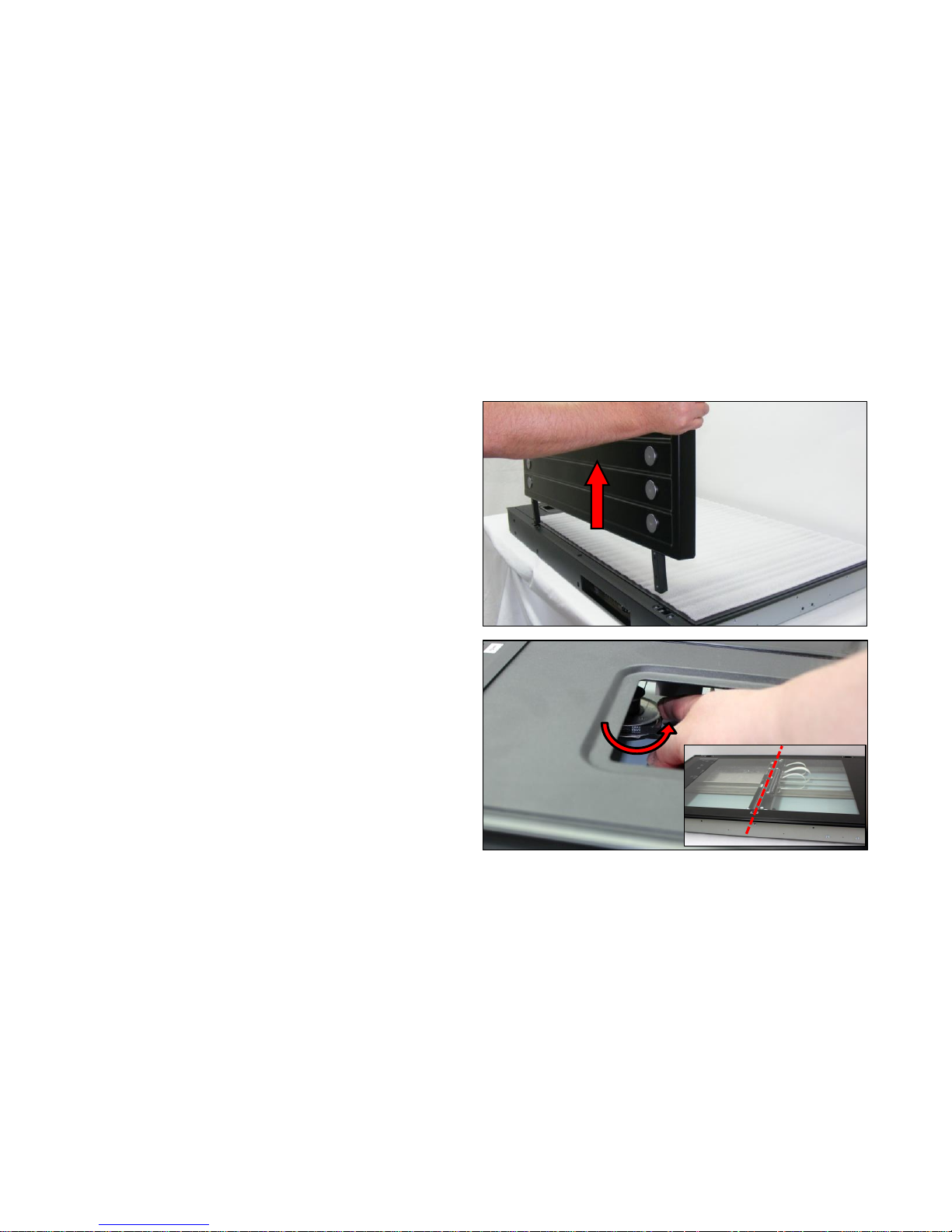
1. Remove the Top Lid Cover as shown on page 21.
2. Remove the tray from the Top Lid Plate and turn the
motor pulley to move the Carriage to the central position
(if it is not already there).
Page 84
Page | 84
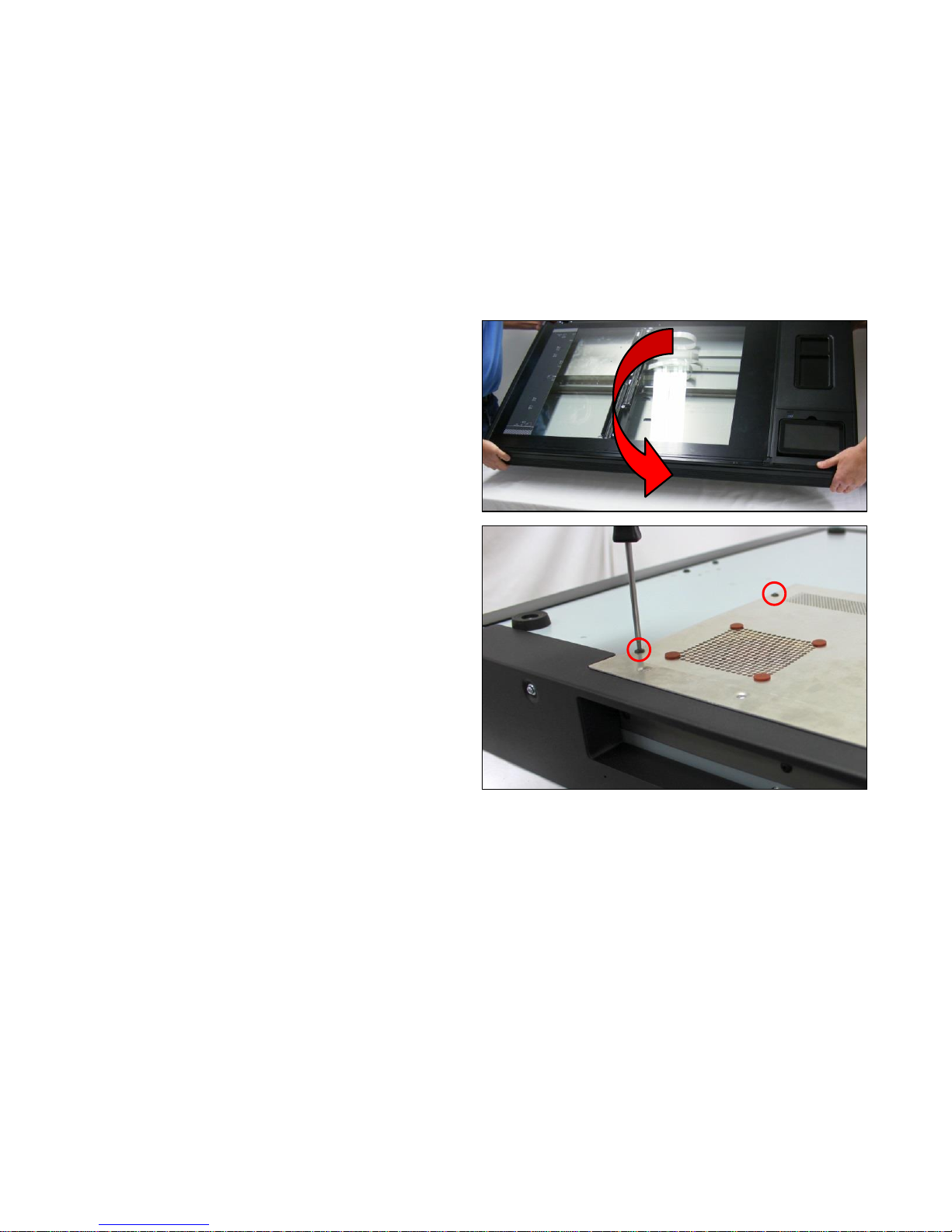
3. Rotate the scanner unit over, and place face down on a
soft cloth to prevent damage. Two people are required
for this.
4. Remove the 4 x T10 screws from the bottom plate.
Page 85
Page | 85
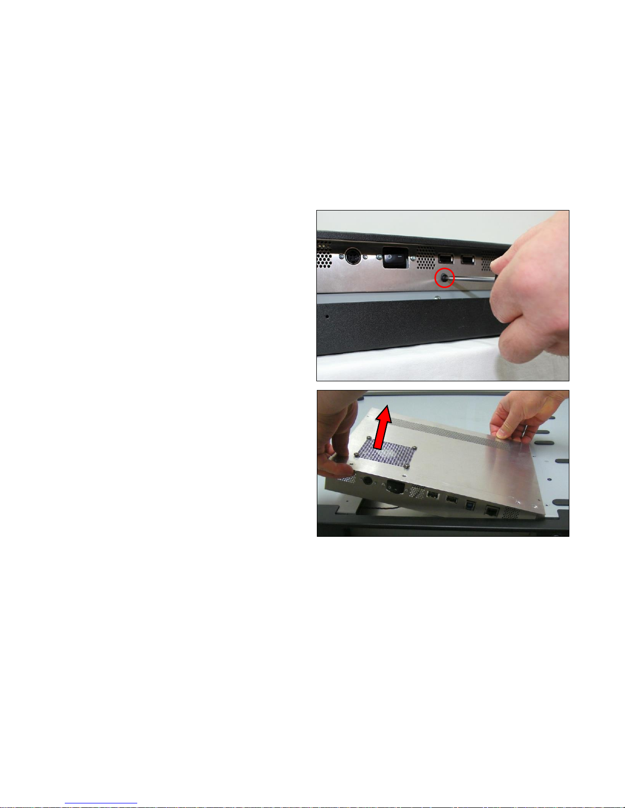
5. Remove the 3 x T10 screws from the front of the bottom
plate.
6. Carefully lift the bottom plate, but be aware the
Controller Board has cables attached, so the plate will
not lift straight off.
Page 86
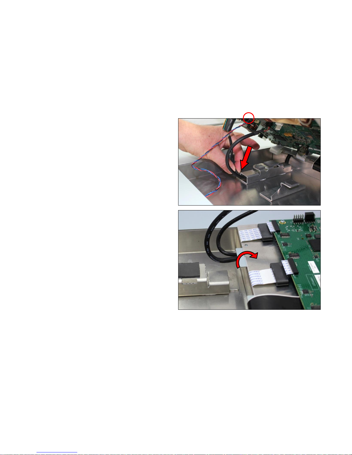
Page | 86
7. Release the 2 cables from the earthing block, and
disconnect the sensor cable to allow the plate to open
fully.
8. Lay the panel, with the Controller Board, flat against the
Scanner unit.
WARNING: Take great care not to damage the Ribbon cables when
laying the plate down.
Page 87
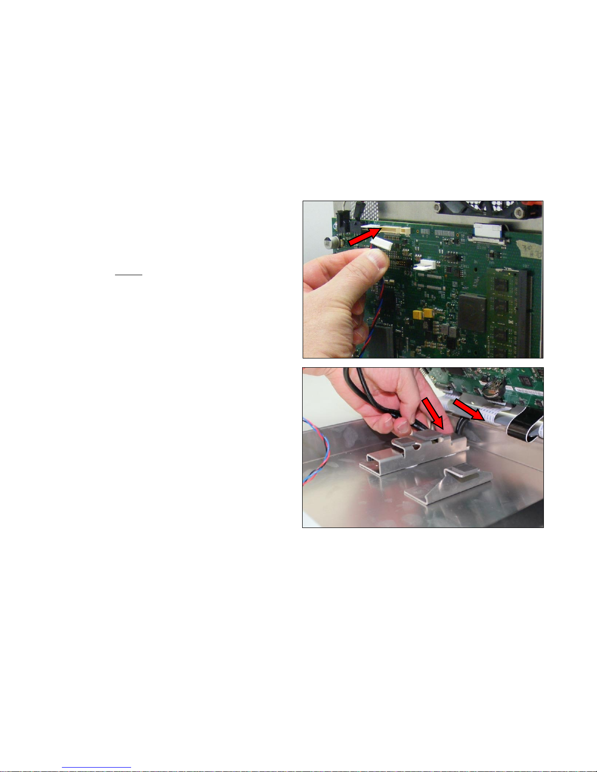
Page | 87
9. To close the panel up, reconnect the sensor cable into
the connector while holding the Controller Board panel at
90 degrees to the scanner chassis.
10. Push the 2 cables securely into the earthing block.
Page 88
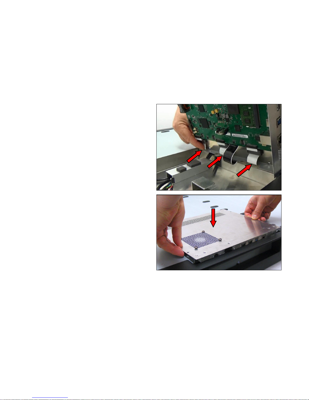
Page | 88
11. Make sure the CIS cables are pushed through as much
as possible to allow full movement of the carriage
12. Taking care not to trap or damage any cables, position
the Controller Board panel into the scanner chassis.
Page 89
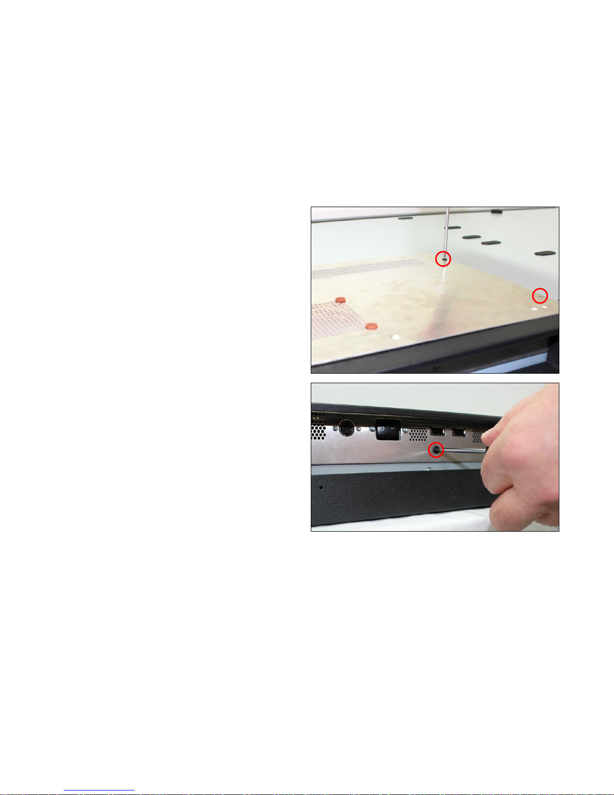
Page | 89
13. Replace the 4 x T10 screws to hold the panel to the
scanner chassis.
14. Replace the 3 x T10 screws to the front of the panel.
Page 90
Page | 90
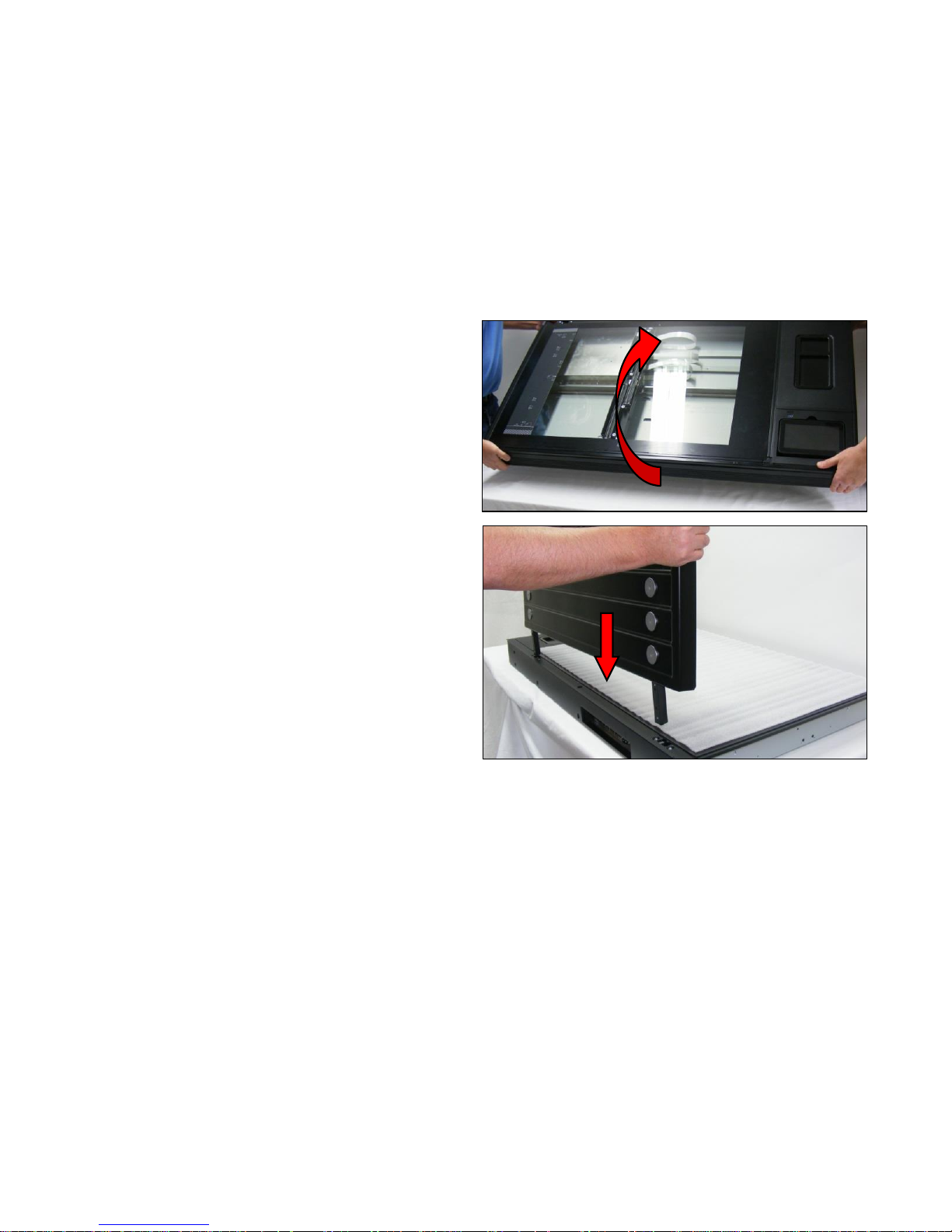
15. Rotate the scanner unit back over into its normal
operating position. Two people are required for this.
16. Refit the Top Lid Cover as shown on page 21.
17. When the scanner is powered up, the carriage will automatically return the correct position.
Page 91
Page | 91
6.13 Controller Board
Tools Required:
T10 Screwdriver
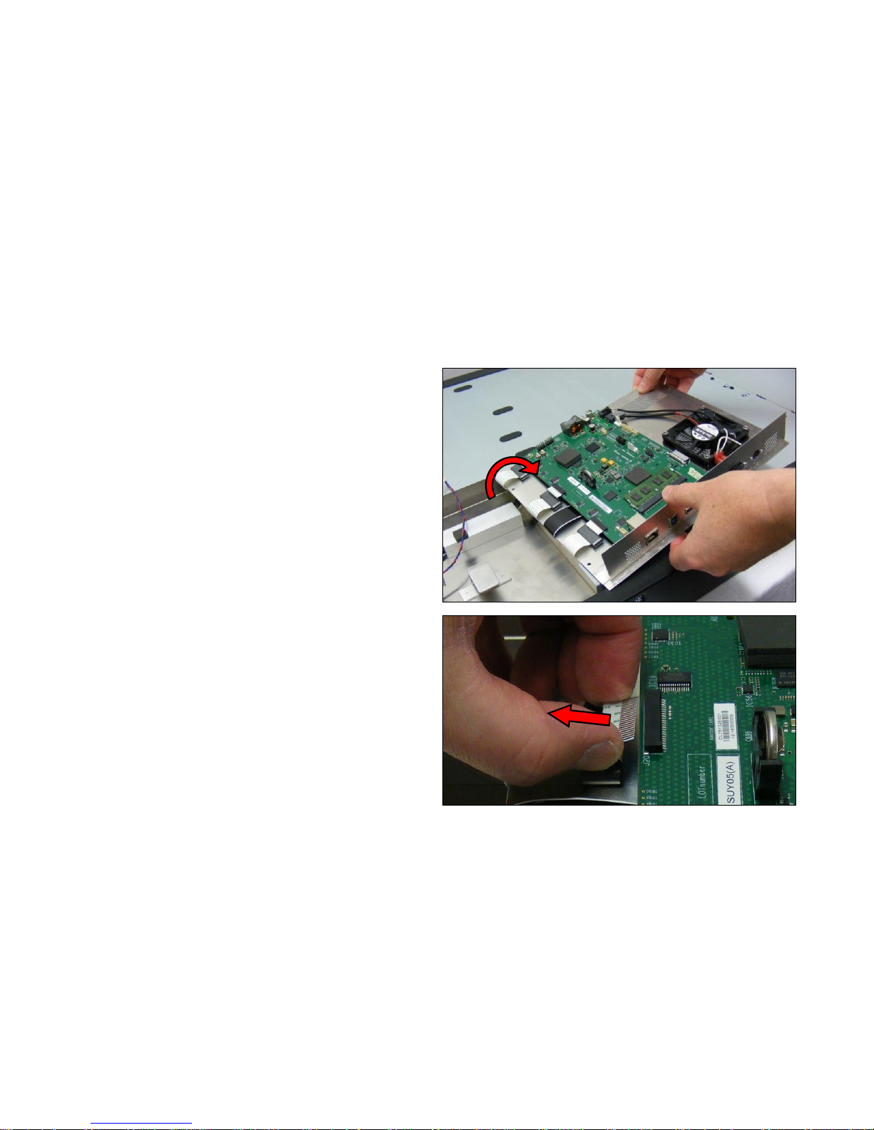
1. Open the Controller Board Panel as shown on page 83.
2. Carefully pull the CIS ribbon cables out of the connector.
Page 92
Page | 92
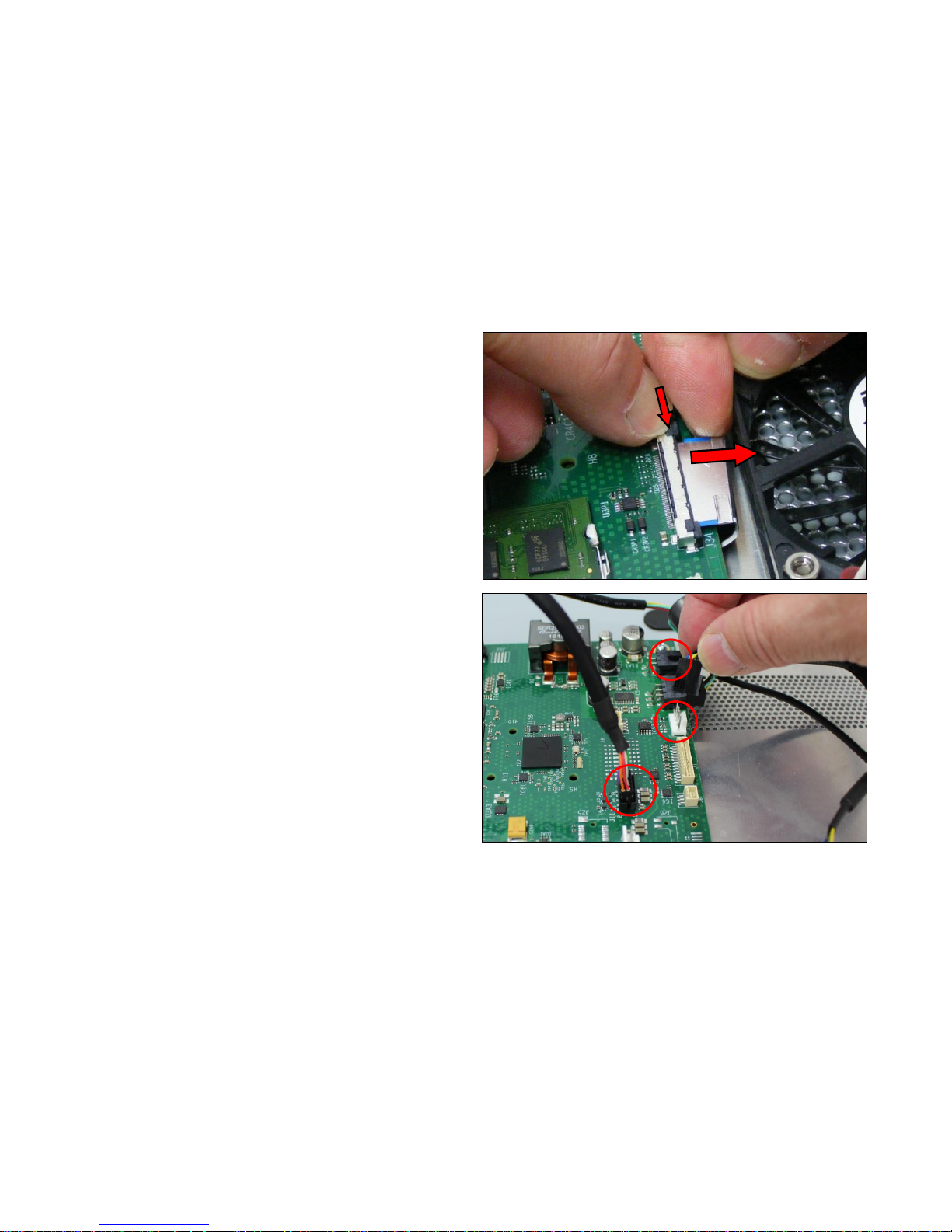
3. While pressing the retaining buttons down , pull the
touchscreen ribbon cable out from its connector.
4. Disconnect all the remaining cables attached to the
Controller Board.
Page 93
Page | 93
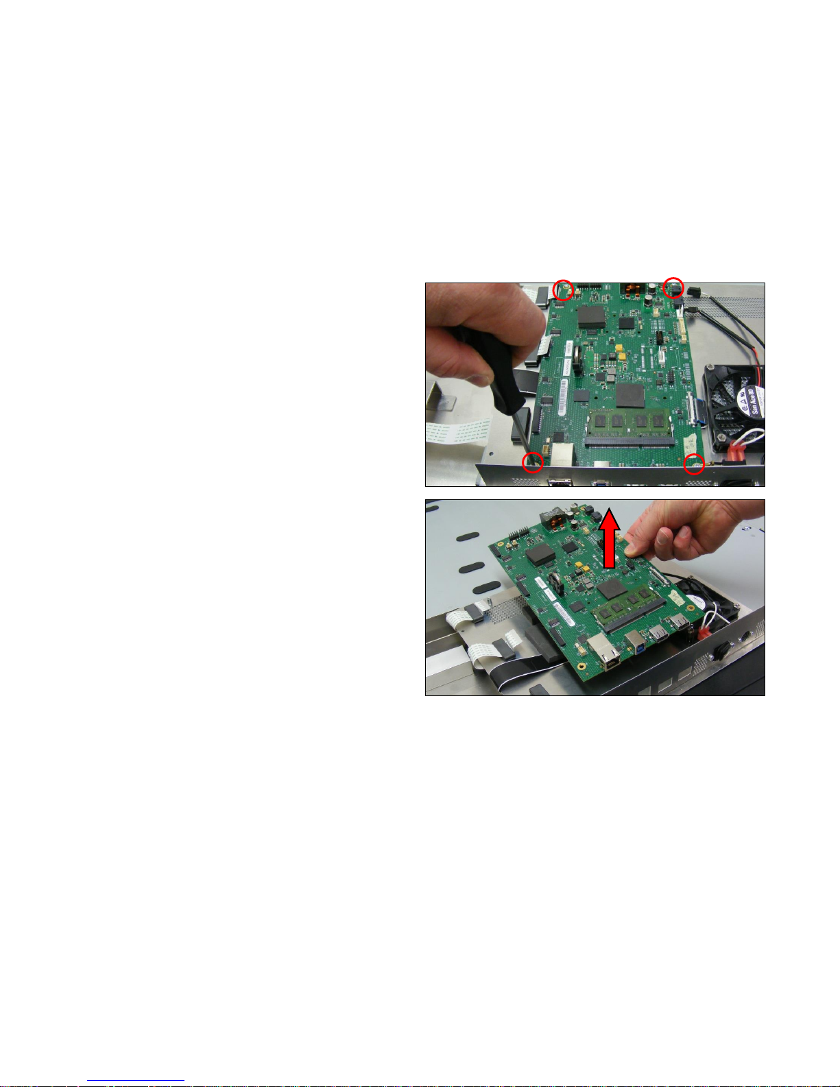
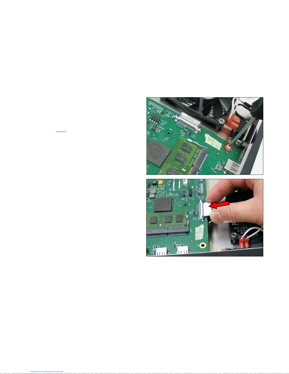
5. Remove the 4 x T20 screws holding the Controller Board
to the panel.
6. Using Anti-static precautions, remove the Controller
Board.
Page 94
Page | 94
7. To refit, position the Controller Board onto the standoffs,
with the USB / Ethernet connectors through the cutouts
on the panel. Replace the 4 x T20 screws, making sure
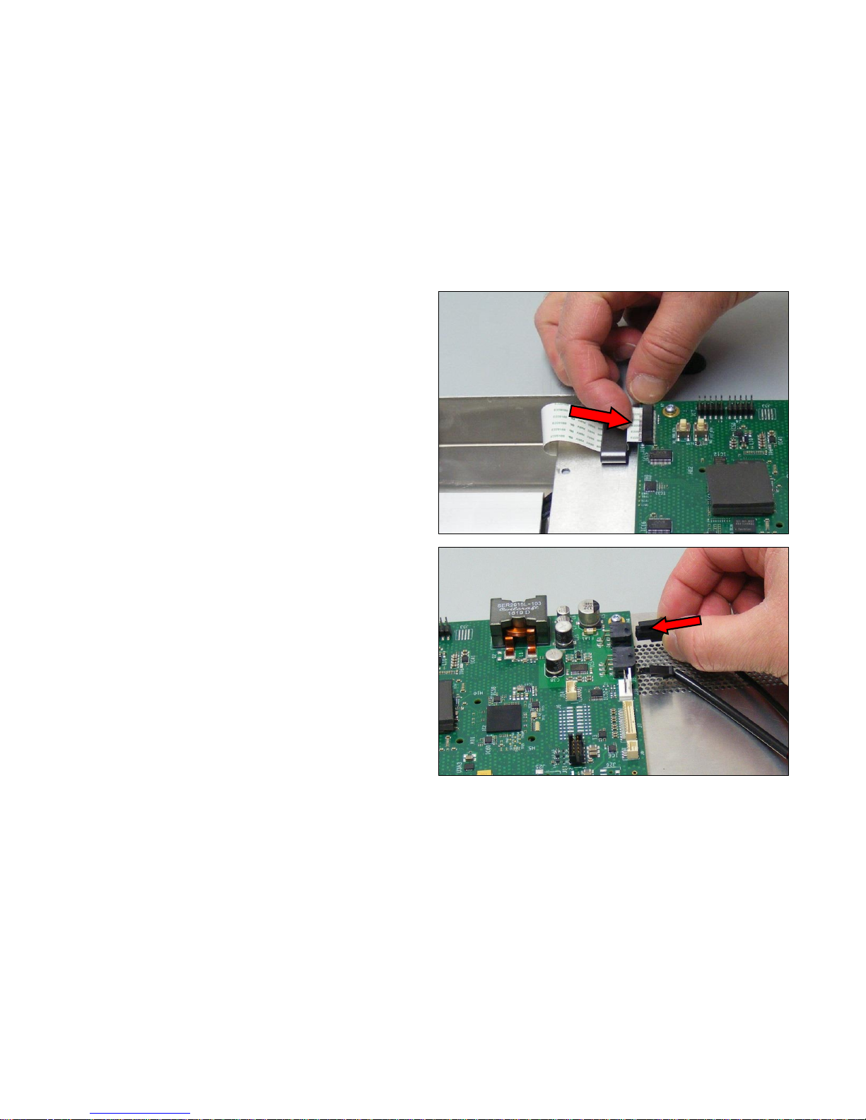
the earthing cable is fitting under the front screw.
8. Press fit the Touchscreen ribbon cable into the
connector on the Controller Board.
Page 95
Page | 95
9. Press fit the CIS ribbon cables into their respective
connectors.
10. Refit all the cables into their appropriate connectors.
Page 96
Page | 96
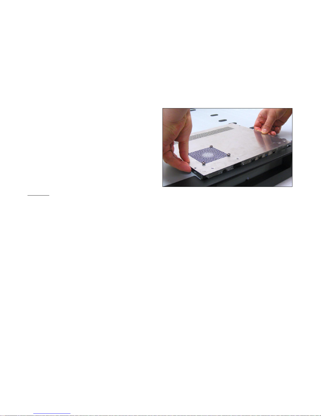
11. Close the Controller Board Panel as shown on page 83.
Post actions.
Since the scanner has a new Controller board it will boot up as “Not Activated”. See page 103 for further instructions on how to reactivate the scanner. Since
it’s a new board it does not hold any calibration data and will therefore will need to be calibrated.
Page 97
Page | 97
6.14 Power Switch and Connector
Tools Required:
T10 Screwdriver
T8 Screwdriver
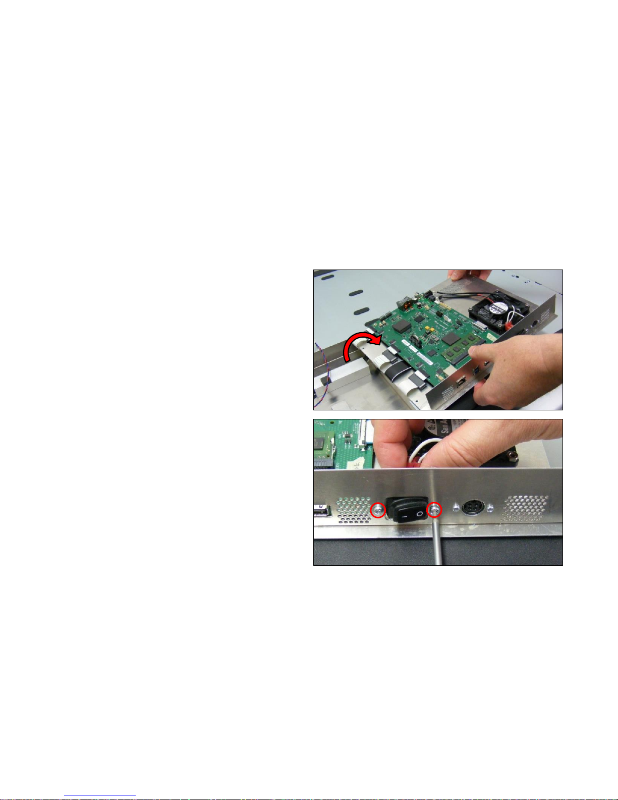
1. Open the Controller Board Panel as shown on page 83.
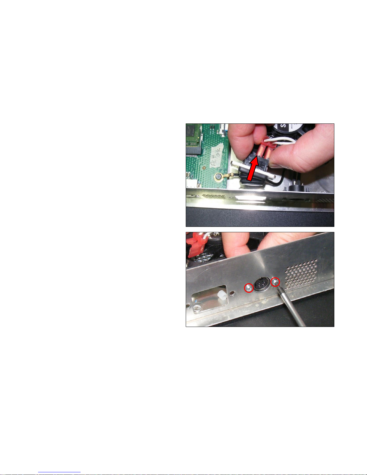
2. Remove the 2 x T10 screws from the Power Switch.
Page 98
Page | 98
3. Remove the Power Switch. Do not lose the 2 plastic
spacer that fits over the 2 x T10 screws, which space the
switch from the panel.
4. Remove the 2 x T8 screws, from the power connector.
Page 99
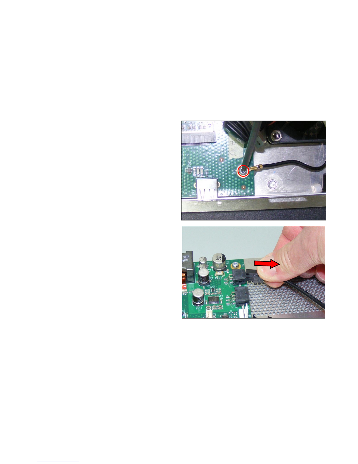
Page | 99
5. Remove the T20 screw and earth cable.
6. Disconnect the cable from the Controller Board.
Page 100
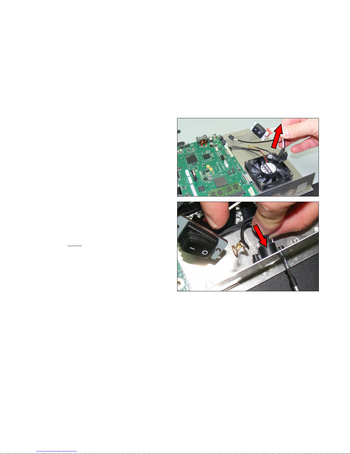
Page | 100
7. Remove the T20 screw and earth cable.
8. To refit, position the power connector in place and
replace the 2 x T6 screws.
 Loading...