

Page 1
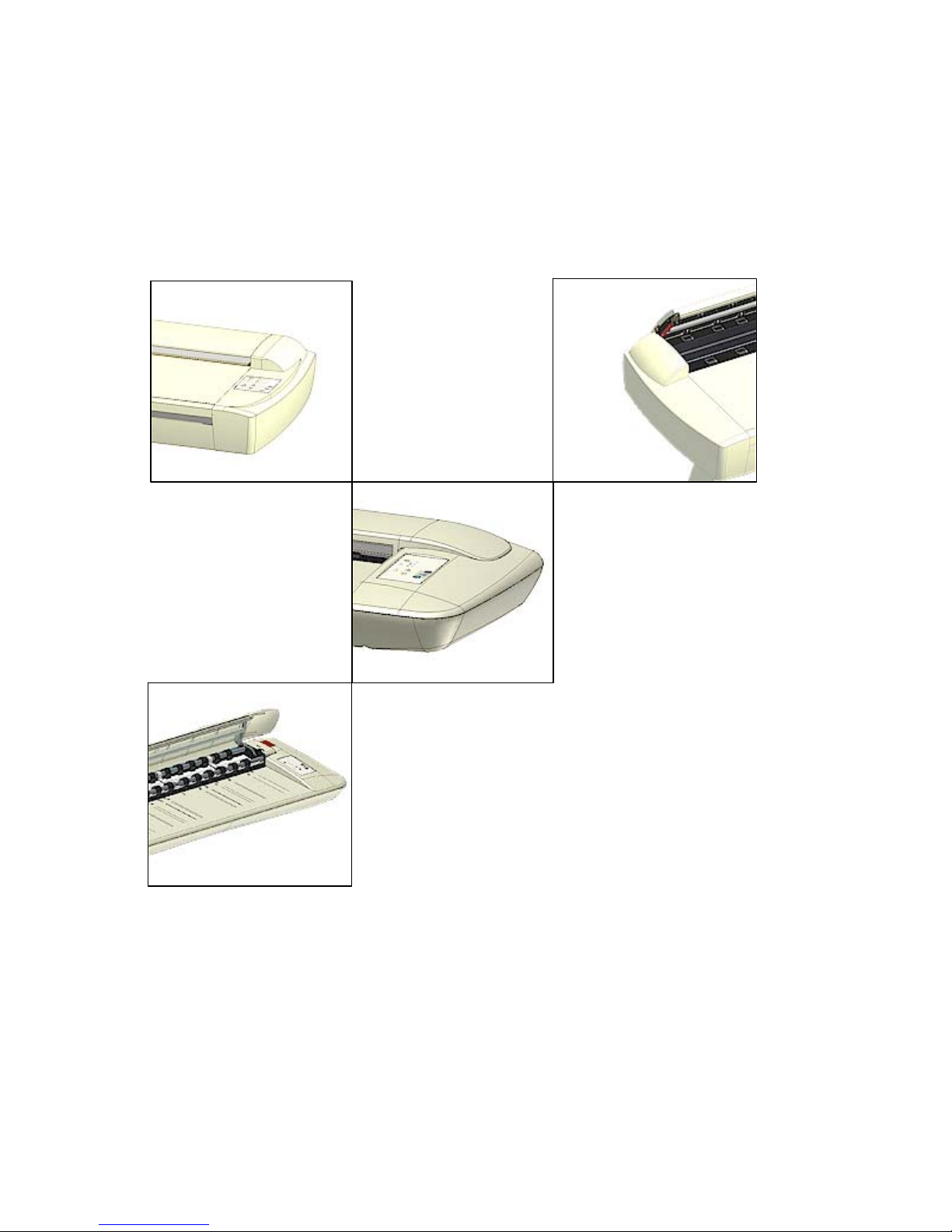
Operator’s Guide
Wide
Format
Scanners
MODELS:
54” - GX67D
42” - GS67D, GT67D, GW67D
36” - GU67D, GV67D
36” - HC68A
25” - GY67D
August, 2006 Edition
Page 2

Table of Contents
1. About This Guide 1-1
2. Scanner System Requirements 2-1
3. Installation 3-1
3.1 Installation Steps 3-1
3.2 Install Drivers and Maintenance Software 3-3
3.3 Set Up the Scan Station 3-4
3.4 Control the Smart Card 3-5
3.5 Select the Scanner Interface 3-7
3.5.1 Description of Interface Types 3-7
3.5.2 Locate the Cable-Connector-Panel 3-7
3.6 Connection through the FireWire Interface 3-10
3.7 Connection through the USB Interface 3-11
3.8 Installation Verification 3-12
3.9 Preliminary Maintenance 3-12
4. Scanner Operation - Panel and Indicators 4-1
4.1 The Operator’s Panel 4-1
4.2 Power – Hard Power and Wakeup/Sleep Modes 4-3
4.3 Application Control – One Touch Scan 4-8
4.4 Media Control from the Panel 4-9
4.5 Setting the Scanner in Firmware BOOT Mode 4-13
4.6 Automatic Power functions 4-14
4.7 Energy Star® 4-14
4.8 Timer Function - Automatic wake-up/sleep modes 4-15
4.9 Idle Time before sleep time 4-16
5. Loading Originals into the Scanner 5-1
5.1 Center-loading 5-1
5.2 Manual-loading and Auto-loading 5-1
5.3 Fast-loading 5-2
5.4 Soft-handling 5-2
5.5 Loading Fragile Originals 5-3
5.6 Pressure Weights – fine-adjusting for optimal pressure 5-3
5.7 Size Settings 5-4
6. Scanning Thick Media 6-1
6.1 Adjustment for Thick Media – Slider Controls 6-1
6.2 Adjustment for Thick Media – Lever Controls 6-3
6.3 Automatic Thickness Adjustment Control 6-4
6.4 When Scanning in Thick Media Positions 6-5
7. Maintenance 7-1
7.1 Regular Scanner Maintenance 7-1
7.2 Cleaning the Scan Area 7-1
7.3 Running the Scanner Maintenance Program 7-6
7.4 Replacing Scanner Parts 7-7
7.4.1 Replacing the Glass-plate 7-8
7.4.2 Replacing the White-Background-Platen 7-10
7.4.3 Replacing the Scanner Lamp-Unit 7-12
7.4.4 Replacing the Dust-Filters 7-14
7.5 Downloading New Firmware 7-16
7.6 Monitoring Your Scanner 7-17
8. Trouble Shooting Common Problems 8-1
8.1 Problems Related to Scanner Installation 8-1
8.2 Problems Related to Operation of the Scanner 8-2
8.3 Problems Related to the Scanning Results 8-5
9. Appendix A: Important Safety Instructions 9-1
10. Appendix B: Regulations 10-1
Page 3

Page 4
About This Guide 1-1
1. About This Guide
This guide explains how to operate and maintain your wide format scanner. The guide assumes
basic knowledge of your computer and operating system and does not repeat material from
their documentation.
Be sure to refer to:
• The Installation Guide – accessed from the menu on the WIDEsystem TOOLS CD-
ROM – describes installation of your driver and scan-to-net setup issues.
• The readme.htm file in the ws folder on the WIDEsystem TOOLS CD-ROM – contains
the most current installation and OS compatibility issues.
• WIDEsystem TOOLS Help – Press F1 after installing and opening WIDEsystem. –
Contains information on using the WIDEsystem application and Scanner Maintenance
software.
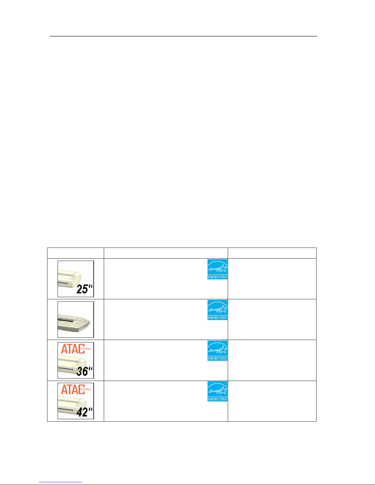
Identify your scanner model icon
This operator’s guide covers several scanner models, although there are individual differences
between the models. Use the guide’s scanner type icons to direct you to descriptions about
your specific scanner model. Topics describing scanner functions that apply solely for specific
models will be marked with one or several of the icons shown in the table below. Topics
describing functions that apply for all models will be marked with all the icons.
Before proceeding, identify the icon that applies to your scanner model. You can then use the
icon throughout this guide to find the function description that applies for your specific scanner.
If in doubt as to which icon refers to your scanner model, see the Model ID on the sticker on the
back of the scanner. Models not listed in the table below are not within the scope of this guide.
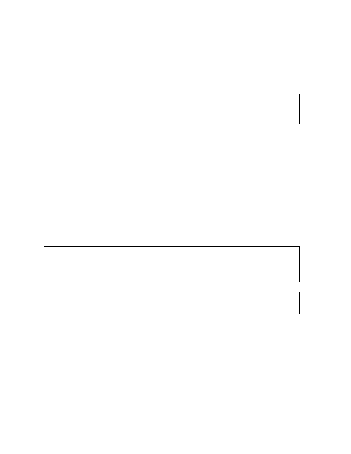
Icon in Guide Applies for scanners…
Model IDs
25” scanners with FireWire and USB
ENERGY STAR
®
compliant.
GY67D
36” scanners with FireWire and USB
Replaceable parts.
ENERGY STAR
®
compliant.
HC68A
36” scanners with FireWire and USB.
ATAC and replaceable parts.
ENERGY STAR
®
compliant.
GU67D
GV67D
42” scanners with FireWire and USB
ATAC and replaceable parts.
ENERGY STAR
®
compliant.
GS67D
GT67D
GW67D
Page 5

About This Guide 1-2
54” scanners with FireWire and USB
ATAC and replaceable parts.
ENERGY STAR
®
compliant.
GX67D
Page 6

System Requirements 2-1
2. Scanner System Requirements
On All Scanners
• PC or supported workstation.
• Compatible Windows operating system – View the ws/readme.htm file on the
WIDEsystem TOOLS CD-ROM.
• USB port, enabled FireWire Port, or an SCSI interface-kit matching your workstation.
• The WIDEsystem TOOLS CD supplied with your scanner.
• Scanning software and compatible third party software.
• Grounded power outlet.
Page 7
Installation 3-1
3. Installation
3.1 Installation Steps
On All Scanners
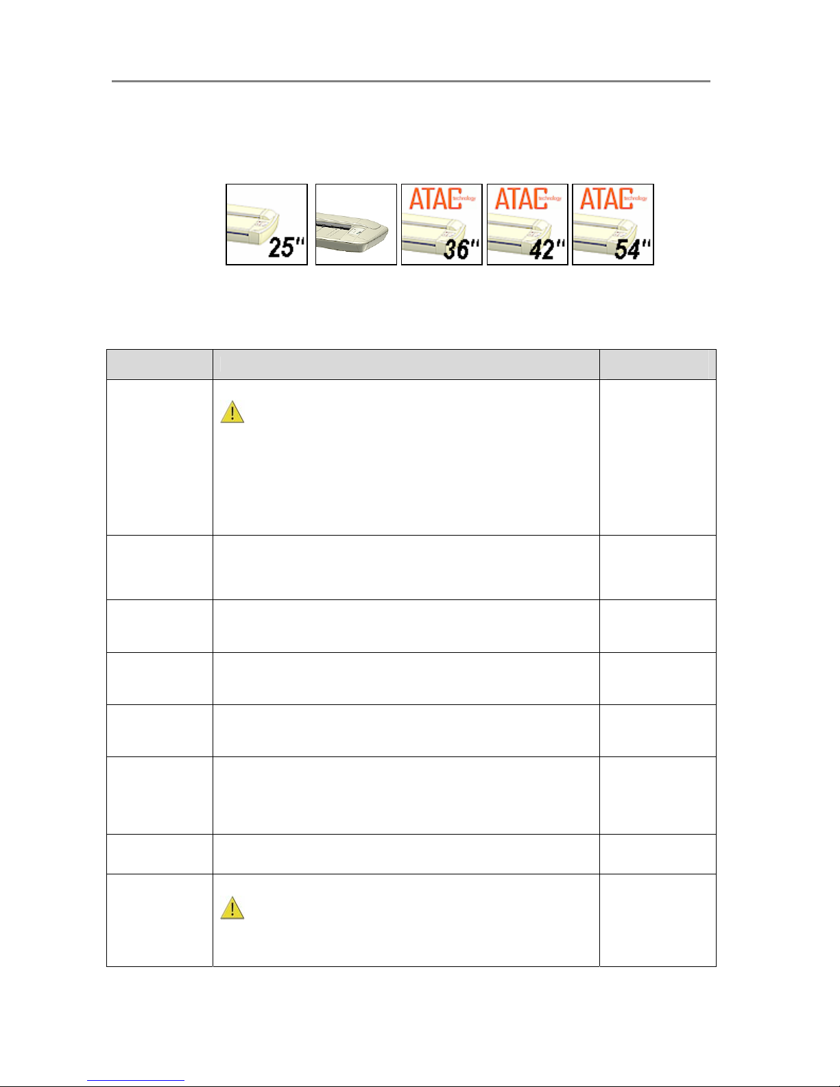
To get your scanner up and running, follow the steps below in their written order. You will find
detailed descriptions of each step in the sections specified under the column “Instructions in
section…”.
Step number Description
Instructions in
section…
1 Insert WIDEsystem TOOLS CD-ROM into your PC.
IMPORTANT : DO NOT YET CONNECT THE SCANNER TO
POWER OR PC.
You will install WIDEsystem before you connect the scanner or install any
scanner software applications. Your scanner drivers are automatically
installed with WIDEsystem and your PC will then be fully prepared to
detect and setup the newly connected scanner device.
Start up the WIDEsystem TOOLS CD-ROM by inserting the CD-ROM into
your PC. Normally the setup program interface will start automatically. If it
does not, see section 3.2 for instructions on manual startup.
3.2
2 Install WIDEsystem software
Click on the option Install WIDEsystem Software from CD main menu or
run the setup.exe program directly from the WIDEsystem (ws) folder on the
CD-ROM. Follow the installation instructions that appear on your screen.
3.2
3 Install Scanner Maintenance Software
Click on the option Install Scanner Maintenance Software from CD’s
menu. Follow the instructions that appear on your screen.
3.2
4 Shut down (power off) the PC
Your PC is now prepared and must be powered off before connection with
the scanner.
5 Perform Preliminary Maintenance – Cleaning
Clean your scanner’s flat surface so dirt and dust are not dragged into the
scan area with the original. Clean the internal Scan area.
3.10, 7.2
6 Set up your scan station and control the smart card
Your wide format copy scanner should be placed either on the specially
designed stand-alone floor stand or on a sturdy table. For sheet feed
models, make sure there is enough space behind the scanner to allow the
media to run out. Make sure that the scanner’s smart card is in place.
3.3, 3.4
7 Connect interface cable to scanner and PC
3.5, 3.6, 3.7, 3.8
8
Connect scanner power cable
The scanner is equipped with a three-wire (pin) grounding type plug. If
you cannot insert the plug into your outlet, contact your electrician to
replace the outlet and ensure a grounded power connection. Do not try to
defeat or ignore the purpose of the grounding-type plug.
Page 8
Installation 3-2
9 Turn on the Scanner
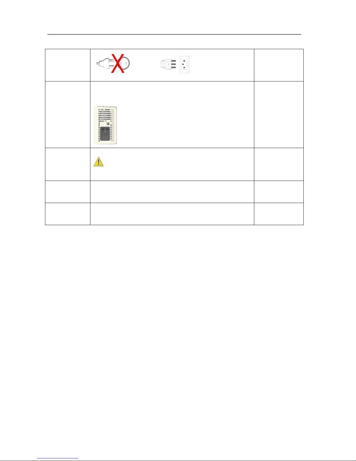
To turn on the scanner - at back of the scanner, plug in the power cable
and flip the Outlet Switch to ON. The scanner starts the init and self test
sequence.
Power outlet and switch is found at the back of the scanner
10
Turn on the PC
Make sure the PC connected to the scanner is likewise power-
connected to a grounding-type power outlet with a three-wire (pin)
grounding type plug.
11
Verify installation of new hardware
Double click on the WIDEsystem scanner icon on the Windows system
tray. The program should detect a Selected Scanner in the dialog.
3.9
12
Run preliminary Scanner Maintenance - Maintenance program
Left click on the WIDEsystem scanner Icon and select Launch Scanner
Maintenance from the menu. Follow the instructions on your screen.
7.3
Page 9
Installation 3-3
3.2 Install Drivers and Maintenance Software
On All Scanners
Before connecting the scanner, you must install its basic drivers and maintenance utilities on
your PC. The basic drivers and maintenance utilities are installed from the WIDEsystem TOOLS
CD-ROM that came with your scanner.
Important: Be sure to install WIDEsystem before you connect the scanner or install any
scanner software applications. Your scanner drivers are automatically installed with
WIDEsystem and your PC will then be fully prepared to detect and setup the newly connected
scanner device.
If you connected and tried to install the scanner before installing WIDEsystem, the scanner will
be entered on the system as a new device without functional drivers. The scanner will be
displayed in the Windows Device Manager with a yellow error icon. The scanner entry must be
removed from the Device manager before re-installing.
Important: Be sure to use the WIDEsystem TOOLS CD-ROM that came with your scanner
or a newer version. Out-of-date versions of WIDEsystem software may not detect your scanner
model.
To install the basic drivers and maintenance software:
1. Start up the WIDEsystem TOOLS CD-ROM - Insert the CD-ROM into your PC.
Normally the setup menu interface will start automatically. If it does not, perform the
following steps to activate it.
a. Click the Start button on the taskbar and choose Run from the menu.
b. Type D:\setup in the Command Line Box (where D: represents the name of
your CD-ROM drive).
c. Select the OK button.
2. View Installation Instructions - Click on the CD’s Installation Guide option to view
additional installation instructions.
3. Install WIDEsystem and drivers - click on the option from main menu or run the
setup.exe program directly from the WIDEsystem (ws) folder on the CD-ROM. Follow
the instructions that appear on your screen.
4. Install the Scanner Maintenance program - click on the option from main menu or run
the setup.exe program directly from the Scanner Maintenance (sm) folder on the CDROM. Follow the instructions that appear on your screen.
Page 10
Installation 3-4
NOTE: On Windows Compatibility - Your scanner and drivers are tested and developed to
support the most current active Microsoft Windows version OS systems. Drivers and interface
support in regard to specific Windows versions will follow the Microsoft Support Lifecycle Policy.
The compatibility specifications can therefore change accordingly. The most current OS
compatibility specifications and drivers will be available on your manufacturer’s website.
3.3 Set Up the Scan Station
On All Scanners
Your wide format scanner should be placed either on the specially designed stand-alone floor
stand or on a sturdy table. Make sure there is enough space behind the scanner to allow the
media to run out. Thick stiff media requires space that is at least as large as the media length.
Slots or openings in the cabinet at the back or bottom are provided for ventilation. This
ensures reliable operation of the product and protects it from overheating. These openings must
never be blocked or covered by placing the unit on a bed, sofa, rug, or other similar soft
surface.
Your scanner should never be placed near or over a radiator or heat register.
You should not place the scanner in a built-in installation unless proper ventilation is
provided.
The scanner is equipped with a three-wire (pin) grounding type plug. This plug will fit only
into a grounding-type power outlet. This is a safety feature. If you cannot insert the plug into
your outlet, contact your electrician to replace the outlet and ensure a grounded power
connection. Do not try to defeat or ignore the purpose of the grounding-type plug.
X
Make sure the PC connected to the scanner is likewise power-connected to a groundingtype power outlet with a three-wire (pin) grounding type plug.
See also the Safety Instructions at the end of this operator’s guide.
Page 11
Installation 3-5
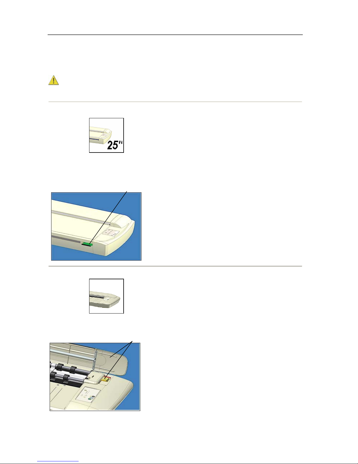
3.4 Control the Smart Card
Check that the Smart Card is correctly installed (contact side downwards) and corresponds to
your scanner model. The scanner will function correctly only with a Smart Card inserted.
Be sure that the scanner is turned off when removing/inserting a Smart Card or
accessing the Smart Card area.
Locating the Smart Card
On Scanners:
You will find the Smart Card in the small drawer labeled “PUSH” behind the scanner front
streamer (slide the streamer towards the left to access the drawer). Notice that the SCSI DIL
switch controls are in the Smart Card drawer. The DIL switches are used only for certain
configurations with SCSI interfacing (described in section Connection through SCSI interface).
Smart Card drawer behind the streamer
Locating the Smart Card
On Scanners:
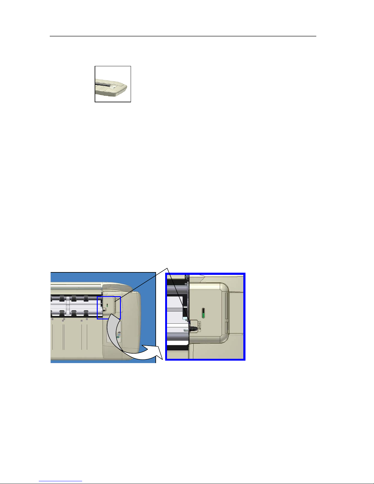
On these models you access the Smart Card by lifting the scanning area lid towards the back.
The Smart Card is placed in its insertion slot on the top right side of the scanner.
Lift the scanning area lid to access the smart card
Page 12
Installation 3-6
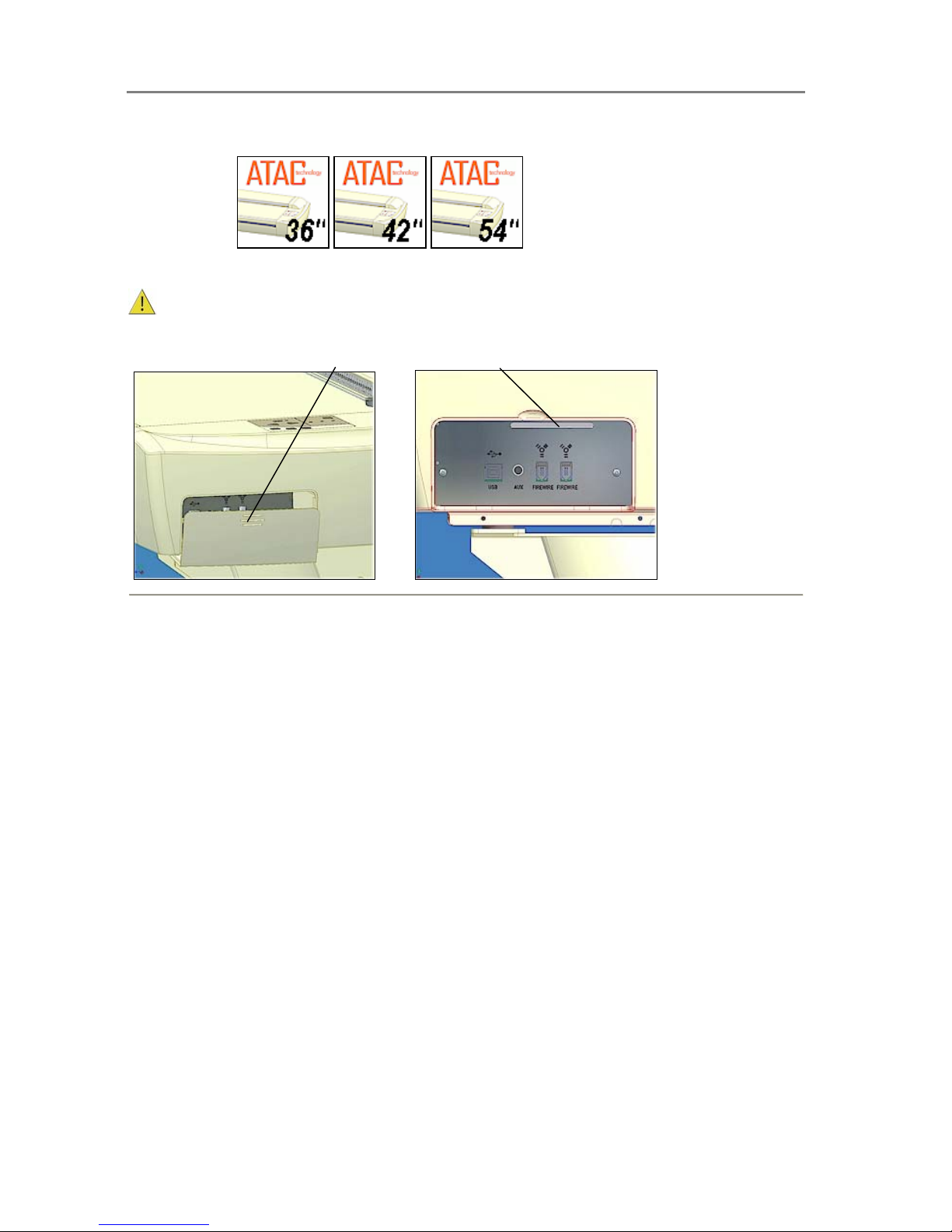
Locating the Smart Card
On Scanners:
On these models you will find the Smart Card by removing the scanner’s right side cover. The
Smart Card is placed in its insertion slot above the scanner interface connectors.
Be sure to reattach the cover after inserting the smart card. The cover must always be
closed before you turn the scanner ON.
Remove the scan ner’s right side cover
Smart Card slot above interface connectors
Page 13
Installation 3-7
3.5 Select the Scanner Interface
Different scanner models support specific types of interface connections. Most scanners
support two different types of interfaces and you need to select the one that is best for your
scanning purposes and compatible with your PC system. The different interface types are
described below.
To see which interface options are available on your scanner:
You can identify the specific interface types available on your scanner model by viewing the
scanner’s Cable-Connector-Panel. (See the next section: Locate the Cable-Connector Panel).
3.5.1 Description of Interface Types
FireWire
FireWire can accommodate 400 megabits (around 50 megabytes) per second, which is more
than adequate for high volume scanning of large formats. FireWire is a plug-and-play (PnP)
specification. FireWire usage requires a FireWire Card and Port installed on the computer. A
FireWire card is supplied with the scanner.
See your Windows documentation for information on OS capability with FireWire.
USB 2.0
With USB connectivity you do not need to open the computer and install cards. USB is a plug-nplay (PnP) specification. The USB 2.0 interface supports a data transfer speed of 480 megabits
making it one of the industry’s most effective interface options. Older computers with USB 1.1
ports will function with a USB 2.0 (scanner) device but at the USB 1.1 (slower) speeds.
See your Windows documentation for information on OS capability with USB.
NOTE: On Windows Compatibility - Your scanner and drivers are tested and developed to
support the most current active Microsoft Windows version OS systems. Drivers and interface
support in regard to specific Windows versions will follow the Microsoft Support Lifecycle Policy.
The compatibility specifications can therefore change accordingly. The most current OS
compatibility specifications and drivers will be available on your manufacturers website.
Regulatory Notice: Your scanner product has been tested to comply with the EMC Standards
EN55022 and FCC, Part 15. To maintain compliance, only use the interface cables supplied
with the scanner.
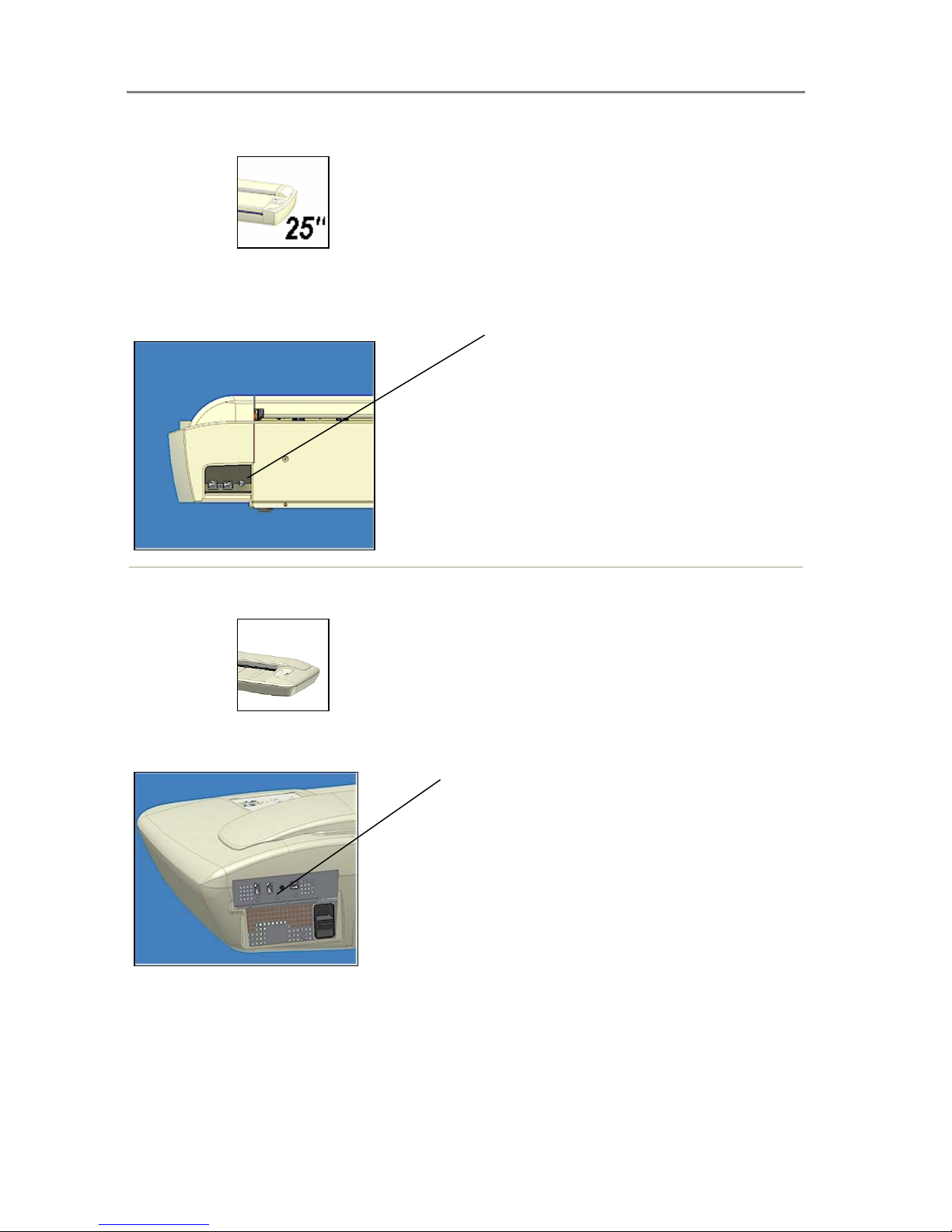
3.5.2 Locate the Cable-Connector-Panel
The interface cable connectors are grouped in a Cable-Connector-Panel. Different scanner
models support different options for interfacing. You can identify the interface types available to
you by viewing the scanner’s cable-connector-panel. You can find your scanner’s cableconnector-panel as follows:
Page 14
Installation 3-8
Locate the cable-connector-panel
On Scanners:
FireWire and and USB connectors. The cable-connector-panel is found on the underside of the
scanner and accessed from the scanner’s back.
Cable-connector-panel is accessed from the scanner’s backside.
Locate the cable-connector-panel
On Scanners:
FireWire and USB interface connectors. The cable-connector-panel is found on the back.
The cable-connector-panel is found on the scanner’s back.
Page 15
Installation 3-9
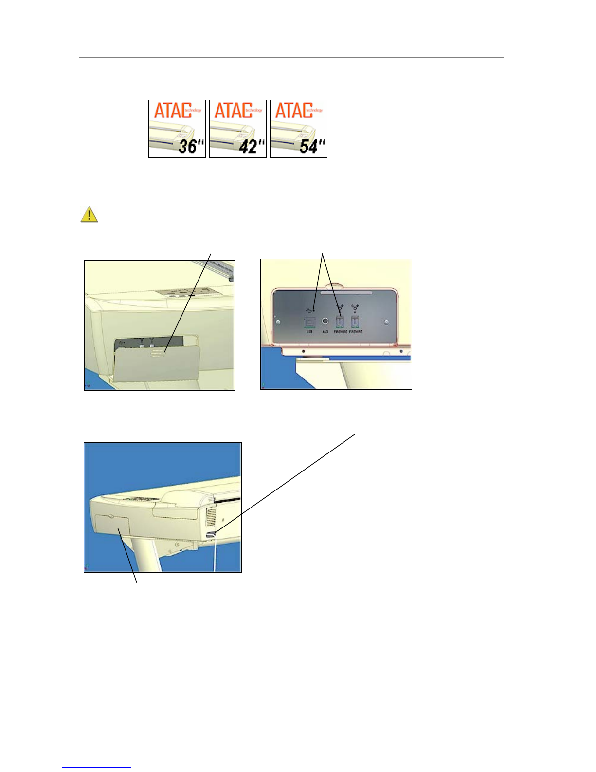
Locate the cable-connector-panel
On Scanners:
FireWire and USB interface connectors. You will find the cable-connector-panel by removing
the scanner’s right side cover. You feed the interface cable through the opening in the back of
the scanner until it emerges in front of the cable-connector-panel.
Be sure to reattach the cover after you connect the interface. The cover must always be
closed before you turn the scanner ON.
Remove the scanner’s right side cover
Interface connectors (cable-connector-panel)
Feed the interface cable through the hole in the back until it emerges in interface are a.
Interface area is behind the cover
Page 16

Installation 3-10
3.6 Connection through the FireWire Interface
To connect through FireWire, you will need the FireWire cable that came with your scanner.
Your computer must be enabled for FireWire through a FireWire card and port.
Check your computer for FireWire
Many computers come with FireWire inputs. Follow these steps to check if FireWire is enabled
on your computer:
1. In Windows, Click Start, Settings, and then Control Panel.
2. Double-click the System icon.
3. Click the Device Manager tab.
If a FireWire host controller (IEEE) is listed, then FireWire is enabled on your computer. If you
do not see this device listed, you will need to install a FireWire card.
To install a FireWire card, shutdown your computer and install the card into an empty PCI slot.
See your computer’s user’s manual for installation of new hardware and the driver installation
information that came with your FireWire card.
Connect scanner to PC with Firewire cable
1. Make sure you have installed WIDEsystem on your PC before you connect the
scanner. Your scanner drivers are automatically installed with WIDEsystem and your
PC will then be fully prepared to detect and setup the newly connected scanner device.
2. Shut down (power off) your PC. Do not connect the scanner power cable or turn on the
scanner.
3. Locate the FireWire cable that came with your scanner.
4. Connect the PC end to the FireWire port on your computer
5. Connect the peripheral end to a FireWire connection socket on your scanner.
6. Connect the power cable to your scanner and turn the scanner on.
7. Turn on the PC. The OS will detect and setup the newly connected scanner device.
8. If an ”Unknown device is found” message appears after you plug in the cable, follow the
steps described below under Unknown device is found message.
Note: The extra FireWire connector is for daisy-chaining another device to your system and not
for interfacing with another PC.
“Unknown device is found” message
If your system has problems detecting the scanner, make sure your FireWire port is enabled
(see above). Make sure you have installed the WIDEsystem software from the CD that came
with your scanner or a newer WIDEsystem version. Make sure you have installed WIDEsystem
before connecting the scanner. You should never attempt to step through device installation
dialogs before installing WIDEsystem. If you have done so, see the trouble shooting section for
instructions on reinstalling.
If your system still does not detect the device, disconnect the FireWire cable, unplug the power
to your scanner and turn off the computer. Wait a few minutes, reconnect the scanner, restart
the PC and turn on the scanner.
Page 17

Installation 3-11
3.7 Connection through the USB Interface
Verify that your scanner’s cable-connector-panel contains a USB port. Your computer must also
have an enabled USB port. You will need the USB cable that came with your scanner.
Check your USB Port
Even if the computer has a USB port, it will not function unless it is enabled. Follow the
instructions below to determine whether your USB port is enabled.
1. In Windows, Click Start, Settings, and then Control Panel.
2. Double-click the System icon.
3. Click the Device Manager tab.
4. Click the plus (+) icon to the left of the Universal Serial Bus Controller item.
If a USB host controller and a USB root hub are listed, then USB is probably enabled on your
computer. If you do not see these devices listed, refer to your computer's documentation or
contact the manufacturer for more information on enabling and setting up USB.
Connect scanner to PC with USB cable
1. Make sure you have installed WIDEsystem on your PC before you connect the
scanner. Your scanner drivers are automatically installed with WIDEsystem and your
PC will then be fully prepared to detect and setup the newly connected scanner device.
2. Shut down (power off) your PC. Do not connect the scanner power cable or turn on the
scanner.
3. Locate the USB cable that came with your scanner.
4. Connect the PC end to a USB port on your computer
5. Connect the peripheral end to the USB connection socket on your scanner.
6. Connect the power cable to your scanner and turn the scanner on.
7. Turn on the PC. The OS will detect and setup the newly connected scanner device.
8. If an ”Unknown device is found” message appears after you plug in the USB cable,
follow the steps described below under Unknown device is found message.
“Unknown device is found” message
If your system has problems detecting the scanner, make sure your USB port is enabled (see
above). Make sure you have installed the WIDEsystem software from the CD that came with
your scanner or a newer WIDEsystem version. Make sure you have installed WIDEsystem
before connecting the scanner. You should never attempt to step through device installation
dialogs before installing WIDEsystem. If you have done so, see the trouble shooting section for
instructions on reinstalling.
If your system still does not detect the device, disconnect the USB cable, unplug the power to
your scanner and turn off the computer. Wait a few minutes, reconnect the scanner, restart the
PC and turn on the scanner.
Page 18
Installation 3-12
3.8 Installation Verification
On All Scanners
1. Locate the scanner icon on the Windows System Tray. This is the WIDEsystem
program icon.
2. Double click on the WIDEsystem program icon.
3. The program should detect a Selected Scanner in the dialog.
4. If the scanner was not installed correctly, a message will inform you that your scanner
could not be detected. If this is the case turn off power to all connected devices and
repeat the installation steps.
3.9 Preliminary Maintenance
On All Scanners
Once you have setup your scanner and verified your installation, it is important that you run your
first maintenance session before working with the scanner. Shipping and transportation of your
scanner from the factory may have affected the camera positions and therefore it is
recommended to run camera alignment and calibration using the Scanner Maintenace program
wizard. But before you do so, you must thoroughly clean the scanner’s flat topside (where paper
rests during scanning) and the internal scan area (glass plate and rollers).
Follow the instructions described in the section Regular Maintenance in this Operators Guide.
Page 19
Scanner Operation - Panel and Indicators 4-1
4. Scanner Operation - Panel and Indicators
This section describes the scanner operator’s panel. The operator’s panel contains LED
indicators and operation keys. The indicator’s function is to display scanner status in relation to
its basic operations such as self-testing and media readiness. Interpretation of the LED
indicator messages and operation of the keys are described in this section. You can always
return to this section to reference specific tasks and LED patterns.
4.1 The Operator’s Panel
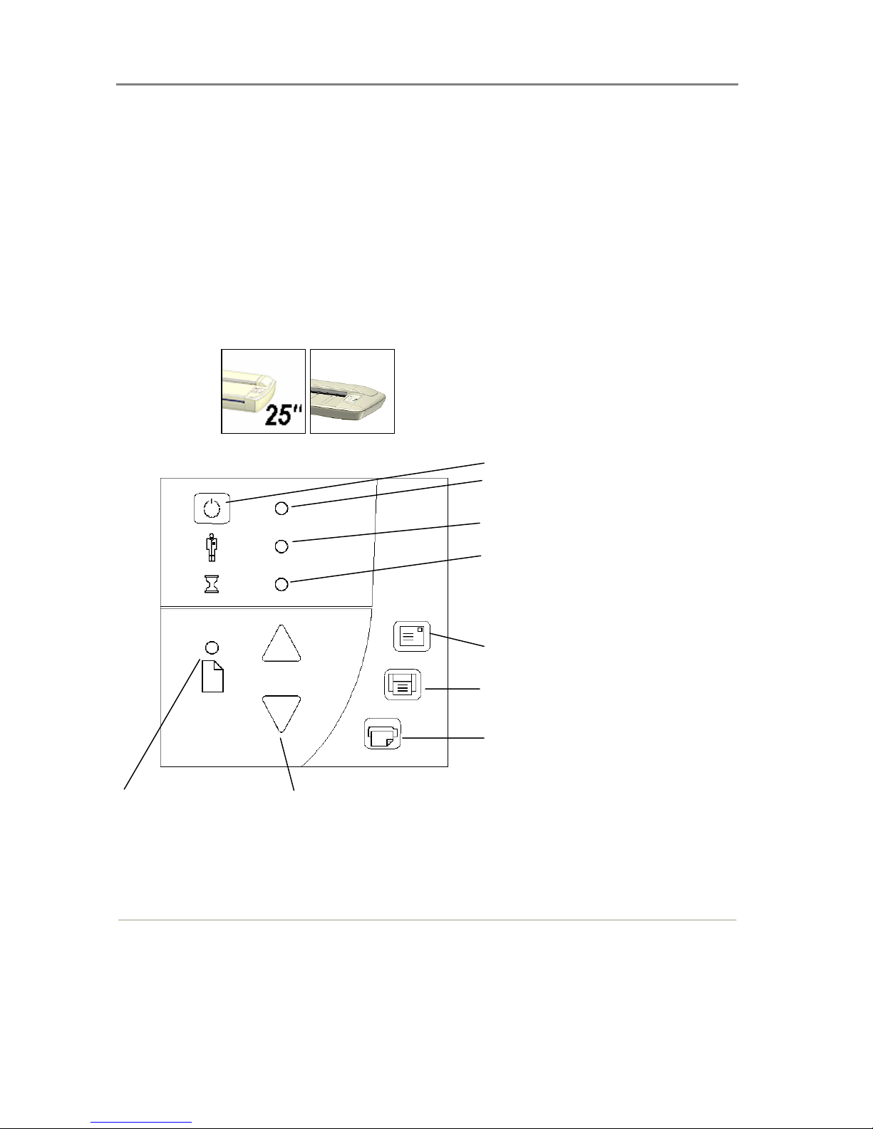
The standard Operator’s Panel
On Scanners:
Paper Ready LED
Power Switch
Power LED
Wait LED
Email Application
Scan Application
Copy Application
Paper Forward/Reverse
Diagnostics LED
The following sections describe usage of the panel keys and the how to understand the panel
LED lighting patterns.
Page 20
Scanner Operation - Panel and Indicators 4-2
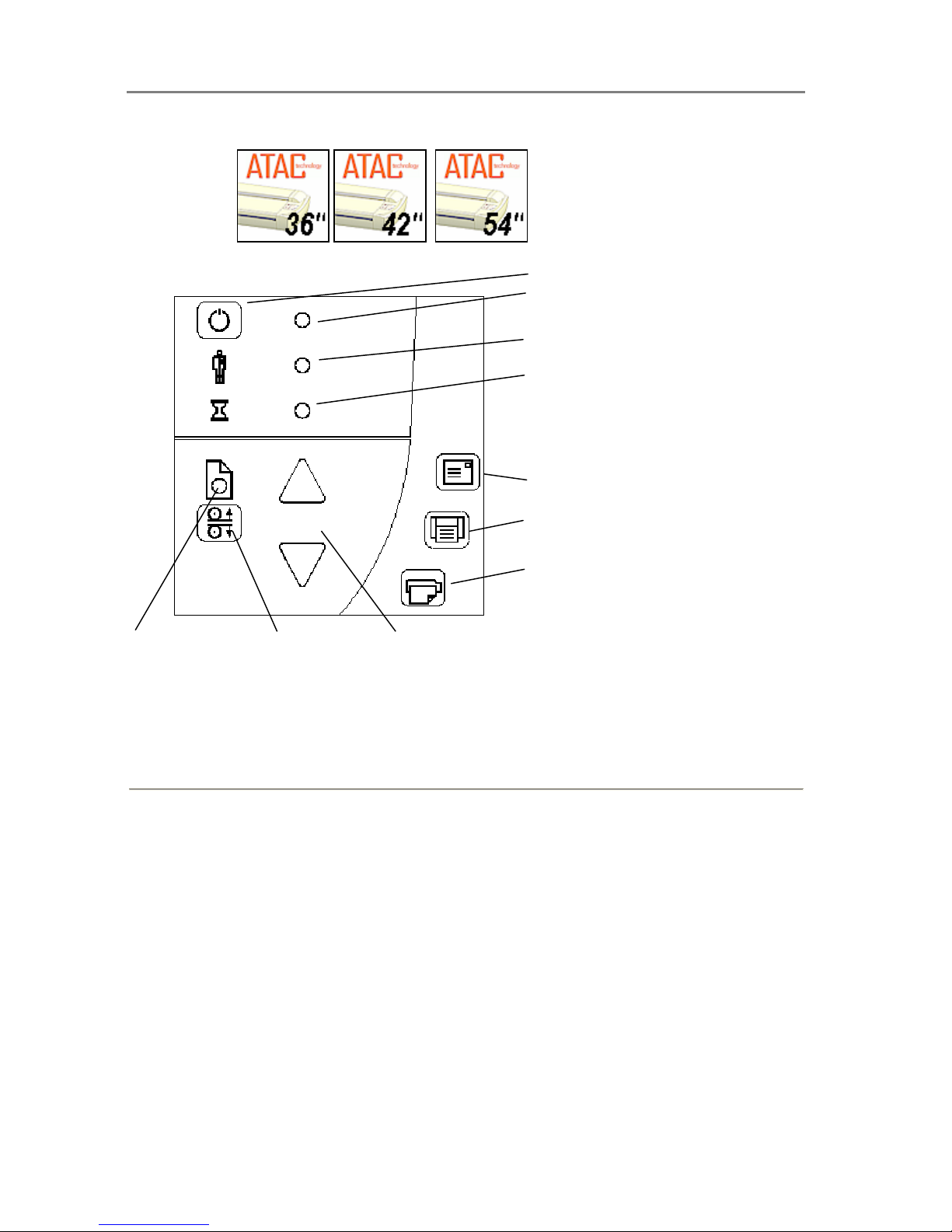
The ATAC Operator’s Panel
On Scanners:
Paper Ready LED
Power Key
Power LED
Wait LED
Email Application
Scan Application
Copy Application
Paper Forward/Reverse Keys
Diagnostics LED
ATAC key
The following sections describe usage of the panel keys and the how to understand the panel
LED lighting patterns.
Page 21
Scanner Operation - Panel and Indicators 4-3
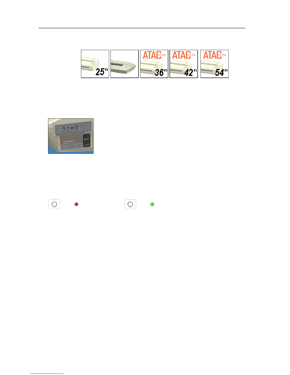
4.2 Power – Hard Power and Wakeup/Sleep Modes
On All Scanners:
Hard Power and Wake-up/Sleep - Two Ways for Turning Power On and Off
• Hard Power ON/OFF
You can power on and off by flipping the outlet switch at the back of the scanner. This is
what you will have to do the first time you turn on power, if you move the scanner to a new
power wall-outlet or if you want to force the scanner into Firmware Boot mode.
• Wake-up and Sleep modes
Turn off and on by pressing the power key on the operator’s panel. The scanner must be
Hard Powered ON – i.e the switch at the scanner’s back must always be ON in order to use
Wake-up and Sleep. Wake-up and Sleep is how you would normally power off and on, and
the switch at the back will always be flipped to ON.
Advantages with using Wake-up and Sleep mode:
Power OFF
Power ON
• You turn the scanner OFF and ON (sleep/wake-up) by pressing the power key on the
panel. The scanner is ready to scan sooner than with Hard Power ON.
• Scanner power with Wake-up and Sleep, can be controlled through the WIDEsystem
software timer feature or an idle time setting. Sleep mode reaches the strict ENERGY
STAR
®
low power values on ENERGY STAR® compliant models).
• The green power LED will blink just before the scanner goes into Sleep mode because
its defined Sleep time (in WIDEsystem) has been reached. If you are using the scanner
and want to cancel Sleep mode, press the power key until the green LED stops
blinking. You can always disable or change timer settings in WIDEsystem.
• When OFF (LED is red) The scanner can be powered up (Wake-up) by pressing the
power key or just by inserting paper into the scanner indicating you wish to use it.
The scanner’s Self Test Procedure
When you connect the scanner to the power outlet and turn on the outlet switch at the back of
the scanner, it starts up with a self-test procedure. The scanner’s self-test procedure consists of
two main steps –
• Init (Initialization) Sequence – the scanner loads and tests internal parameters. Only
initiated when you power up by flipping the outlet switch at the back of the scanner (Hard
Power On).
Page 22
Scanner Operation - Panel and Indicators 4-4
• Self-Adjustment - includes a short warmup period, adjustment of light profiles, stitching
and black/white points. Invoked every time you turn on power with either outlet switch (Hard
Power On) or through power OFF/ON key (Wake-up and Sleep).
The scanner will be ready to scan on completion of its self-test procedure. Normally, after
powering up for the first time, you will leave the outlet switch permanently ON, and turn scanner
power ON and OFF (Wake-up/Sleep) with the Power key on the operator’s panel. To ensure
optimal functionality, the scanner will always run Self-Adjustment when you put the scanner into
Wake-up mode.
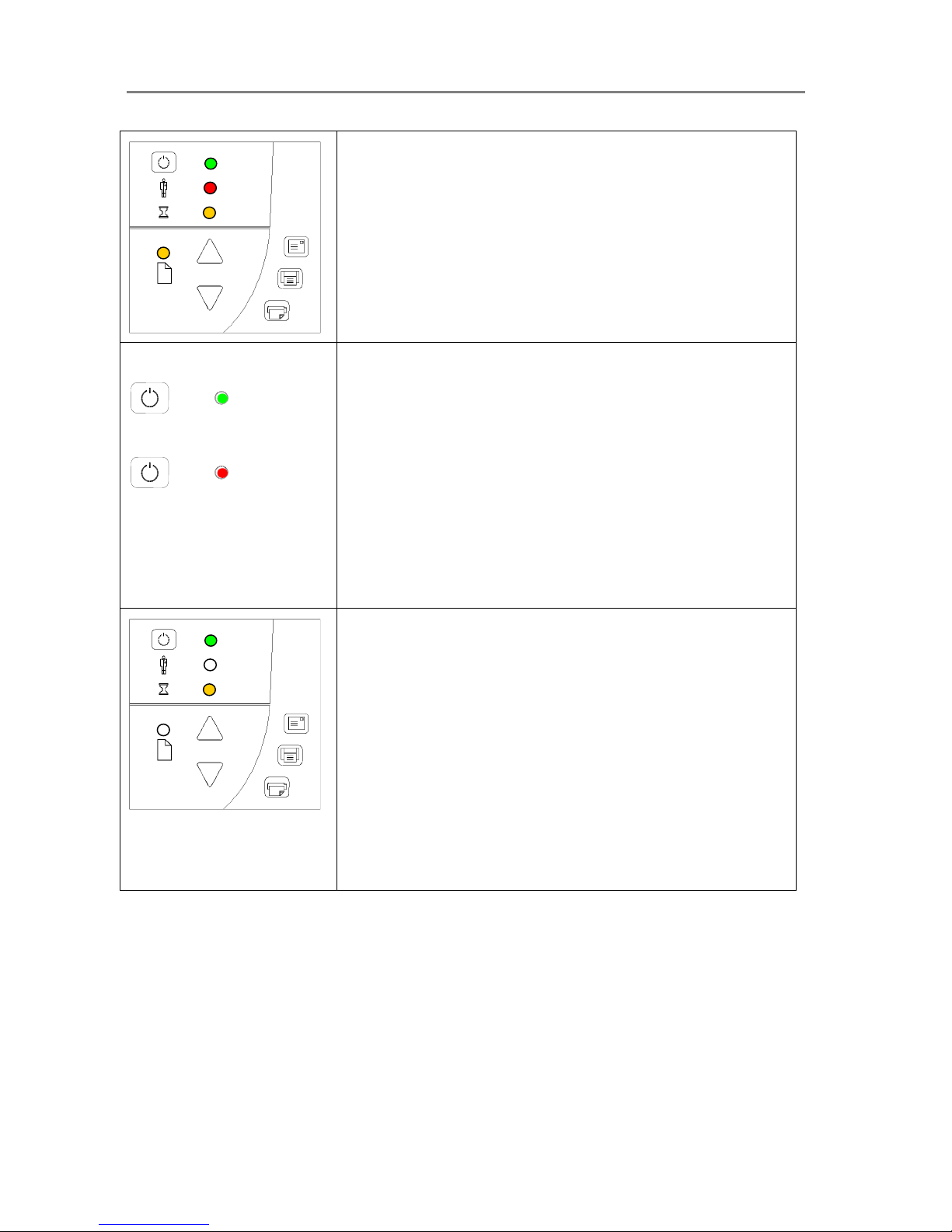
The illustrations below marked “startup – phase 1 (2,3,4)” show how the Operator’s panel will
look (LED lighting patterns) starting from when you turn power ON, through the self-test
procedures and until the scanner is ready to scan.
NOTE: For simplicity, the illustrations below display a Standard Panel i.e., without an ATAC key.
The LED behavior of the Power LED, Diagnostics LED and Wait LED, are identical for Standard
and ATAC operator’s panels.
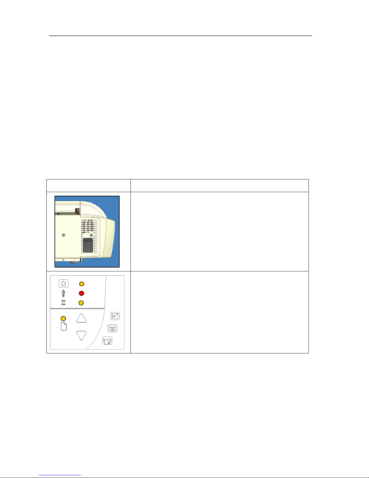
How it looks on scanner… What it means….
Turn the scanner power ON – First Time – Hard Power ON
At back of the scanner, plug in the power cable and flip the Outlet
Switch to ON. The scanner starts the
self-test procedure which
starts with the Init Sequence (see next).
Init Sequence (startup phase 1)
When you invoke Hard Power On by turning scanner power ON from
the outlet at the back, the scanner runs it initialization sequence. ALL
the LEDs are lighted as shown in the illustration on the left.
Panel input is disabled and you cannot begin scanning.
NOTE: When you power up through Wake-up, by pressing the power
key (from red to green) as described in “Wake-up/Sleep modes”, this
initialization sequence is skipped and the scanner goes directly to
Self-Adjustment (startup-phase 3) as described below.
Page 23
Scanner Operation - Panel and Indicators 4-5
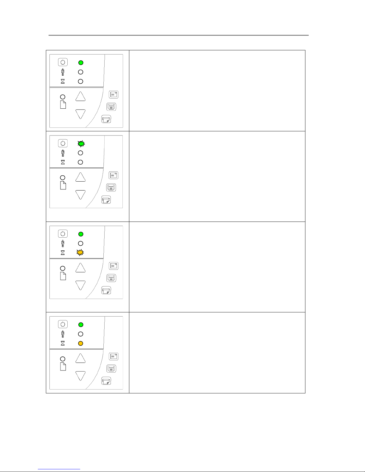
Power LED Green (startup – phase 2)
Towards the end of Init Sequence, the Power LED will change to
green while the other LEDs remain unchanged (lighted).
From here the scanner moves on to Self Adjustment (startup
phase 3).
Power ON
Power OFF
Wake-up / Sleep - Turn power ON/OFF with pow er key –normal
use (with outlet switch always ON)
With the outlet switch always ON, use the Operator’s panel Power key
to control scanner power. Hold down on the Power key to toggle
power into Wakeup and Sleep modes.
The Power LED lights green when the scanner is ON (Wake-up) and
red when power is OFF (Sleep). When you turn the scanner ON in
this manner, it starts in Self-Adjustment mode (startup phase 3) as
described below.
When in the power Wake-up/Sleep mode, the scanner can
automatically be powered up and down (wake-up/sleep) by
WIDEsystem’s timer or an idle time setting. See WIDEsystem Help for
instructions.
Self-Adjustment (startup –phase 3)
If you used Hard Power On - On completion of the Init Sequence,
the power LED (green) and the Wait LED (yellow) remain lighted while
the others LEDs turn off. This indicates that the scanner is running its
Self-Adjustment of light profiles, stitching and black/white points.
If you used Wake-up - the power LED turns to green and the Wait
LED turns on yellow while others LEDs are off. This indicates that the
scanner is running its Self-Adjustment with warm-up and adjustment
of light profiles, stitching and black/white points.
To maintain optimal conditions, the scanner runs new Self-adjustment
procedures periodically during the day (without lighting the wait LED).
If the Wait indicator flashes, the scanner needs to run Self-Adjustment
but cannot (see below).
Page 24
Scanner Operation - Panel and Indicators 4-6
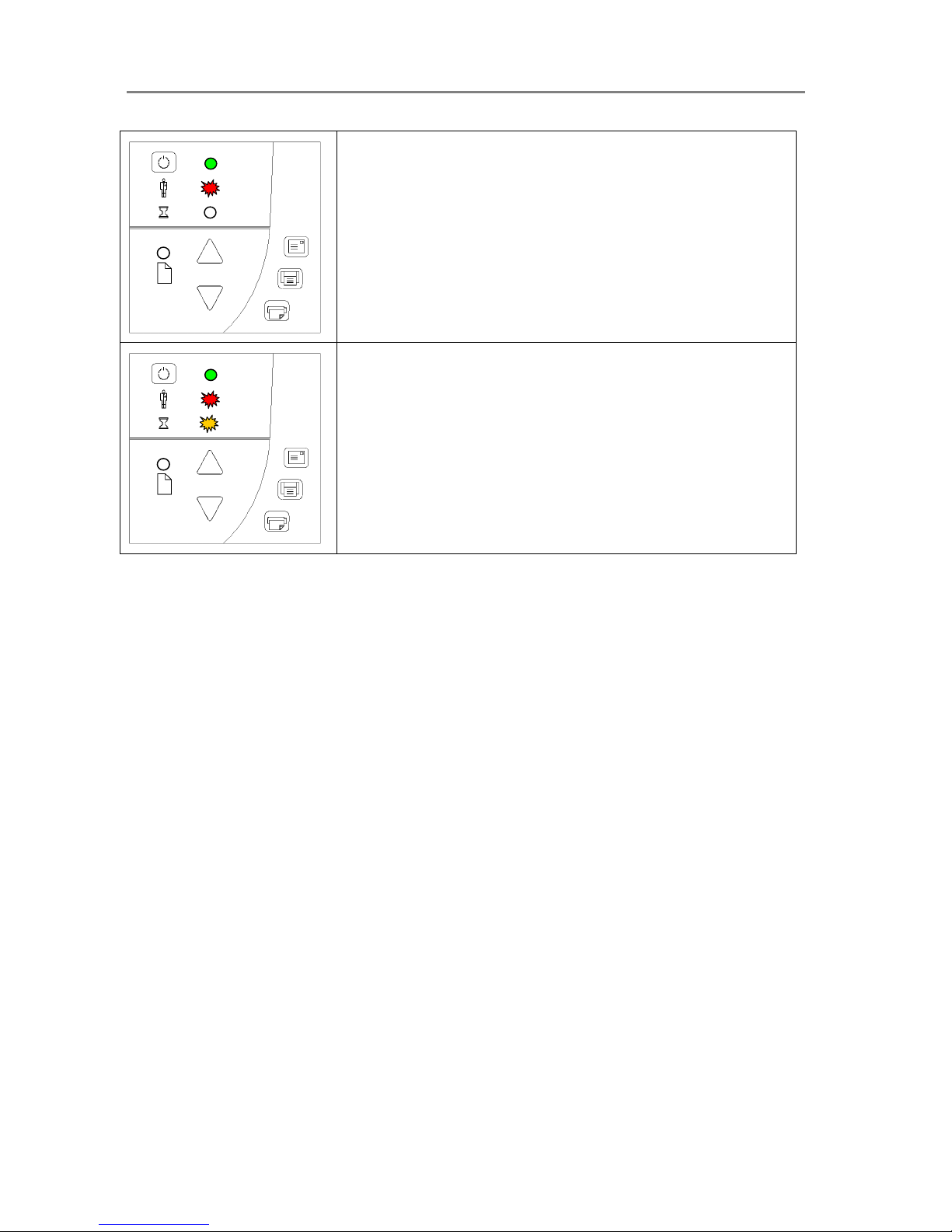
Scanner Ready (startup – phase 4)
When the Wait LED turns off, and only the Power LED is on and lights
green, self-adjustment is completed and the scanner is ready to scan.
Green Power LED flashing
The green power LED will flash just before the scanner
automatically powers off because its defined automatic Sleep
time (in WIDEsystem) has been reached in the timer.
If you are still using the scanner and want to cancel the timer
controlled Sleep mode, press the power key until the LED
stops blinking.
You can at any time disable or change timer settings in
WIDEsystem (see WIDEsystem on-line help for details).
Wait LED Flashes - Self-Adjustment required but not possible
If the Wait LED flashes (and the Diagnostics LED is off) the scanner
needs to run Self-Adjustment but cannot. Self-Adjustment is
necessary for maintaining optimal and stabile internal conditions.
To solve this, any original in the scanner should be removed, and the
pressure-platen should be set to the Normal position (i.e., not a thick
media setting). A scan may be issued, but the quality will be
compromised. When Self-Adjustment is again possible, the Wait LED
stops flashing, but continues to be on until Self-Adjustment is
completed. The scanner should be left alone while Self-adjustment is
running.
During Calibration – Wait LED lights
This is normal. The Wait LED is on during Calibration to indicate that
the original should not be removed or moved during the Calibration
procedure.
All panel input is prevented during basic calibration.
Page 25
Scanner Operation - Panel and Indicators 4-7
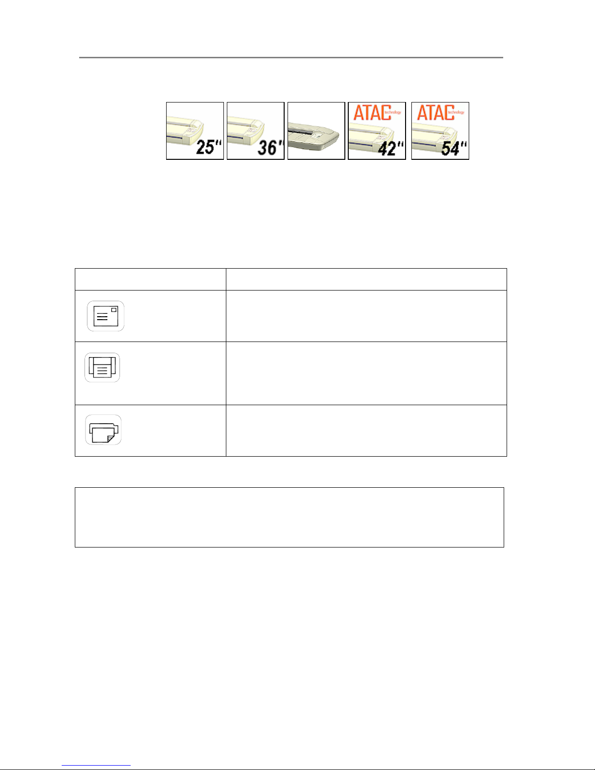
Diagnostics LED Flashes – Error detected during Self-Test
The Diagnostics LED shows the scanner’s Self-Test result status. An
unlit Diagnostics LED means that the scanner’s Self-Test procedures
encountered no errors.
If the Diagnostics LED flashes, an error was discovered during SelfTest. Open WIDEsystem (scanner icon on your system tray) and
select the Status tab to view additional information about the error.
Both Diagnostic LED and Wait LED Flash – Maintenance needed
Simultaneous flashing by both the Diagnostic LED and the Wait LED
may mean that the scanning area needs cleaning and the cameras
calibrated. See the section on "Maintenance" for instructions.
If the Diagnostic and the Wait LEDs continue to flash after scanner
maintenance, there may be camera position errors that require
professional technical service.
Page 26
Scanner Operation - Panel and Indicators 4-8
4.3 Application Control – One Touch Scan
On All Scanners:
The Application Control keys require correct installation of WIDEsystem software, scan
applications and setup definitions before they can become active. Your PC must be turned on
and running.
Descriptions of the key’s intentional functionality follow below. You can however, assign
applications with other functions to any of the Application Control keys. For instructions on
configuring the keys to other applications, view WIDEsystem TOOLS Help
How it looks on scanner…
What it means….
Email Application
This key is for activating an application that scans and prepares
images for sending via E-mail from the scanner.
Scan Application
This key is for activating the scanning application installed on your
PC so as to trigger a scan of the document currently loaded in the
scanner.
Copy Application
This key is for activating a scan-to-copy application installed on your
PC.
NOTE: The applications you wish to use with the buttons must be designed to recognize your
scanner device and the signals sent from its buttons so that when a button is pressed, a scan is
initiated and the result is loaded into the application triggered. Any application you assign to a
button must be specially programmed in order to work in this manner. Check your application’s
documentation to verify its functionality with your scanner’s one-touch-scan buttons.
Page 27
Scanner Operation - Panel and Indicators 4-9
4.4 Media Control from the Panel
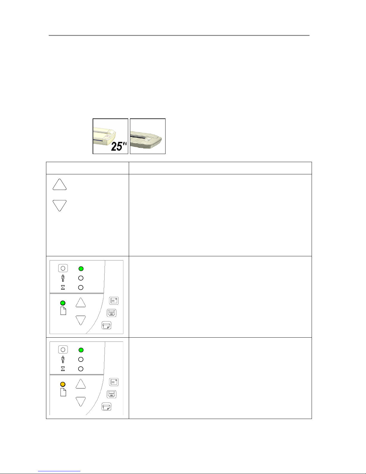
For both thin and thick media, the Paper Ready LED lights up when the media is inserted into
the original’s insertion slot and correctly positioned for feeding on a straight path. The media
can then be moved into the start-scan position by pressing the Paper Forward Key or through
automatic loading. The Paper Ready LED will blink during scanning.
Media Control
On Scanners:
How it looks on scanner… What it means….
Paper Forward and Paper Reverse Keys
The Paper Forward Key moves the drawing into the start-scan position
for manual loading (see section on Loading).
If Auto-Load is applied, loading will occur automatically (without
pressing the key) when the original enters the insertion slot.
Pressing the Paper Forward Key during scanning will stop the scanning
process and feed the original through the scanner while the key is held
down.
The Paper Reverse Key stops the current scanning process and
reverses the original. The original will be fed backwards through the
scanner while the key is held down.
Paper Ready LED Green - Ready for Normal media
The Paper Ready LED lights green when normal thin media is
positioned correctly in the insertion slot and stays green when the media
is moved to the start-scan position.
From there, scanning can be controlled from the computer.
Paper Ready LED Yellow - Ready for Thick media
The Paper Ready LED lights yellow when thick media is positioned
correctly in the adjusted insertion slot and stays yellow when the media
is moved to the start-scan position.
From there, scanning can be controlled from the computer.
Page 28
Scanner Operation - Panel and Indicators 4-10
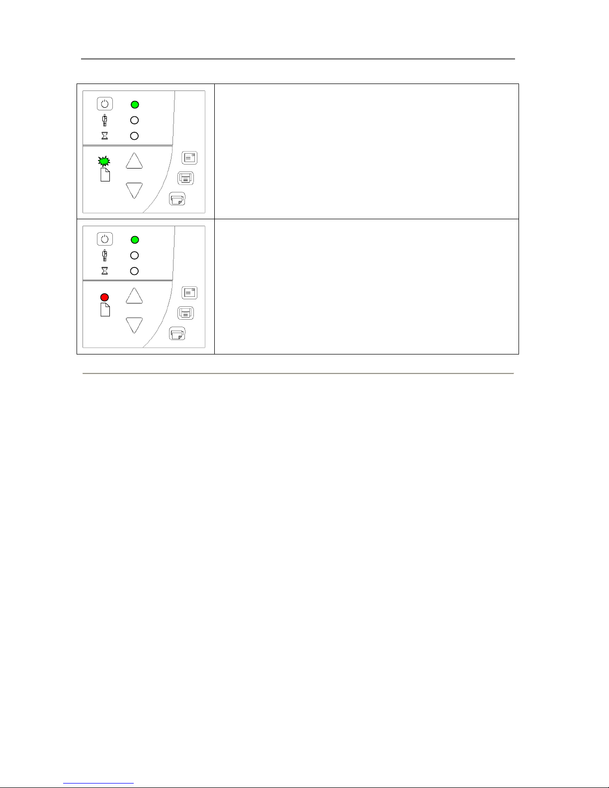
Paper Ready LED Blinks – (green or yellow) – Media is being
scanned
The Paper Ready LED blinks during scanning.
On completion of the scan, the Paper Ready LED will stop blinking.
Scanning can then be repeated from the computer or terminated by
ejecting the media from the scanner.
The above behavior applies for both thin media scanning (green
blinking) and thick media scanning (yellow blinking).
Paper Ready LED Red – No Thick media detected
The paper ready indicator will light red if the pressure-platen is in a thick
media setting (a raised pressure-platen) but the scanner does not detect
the media.
Page 29
Scanner Operation - Panel and Indicators 4-11
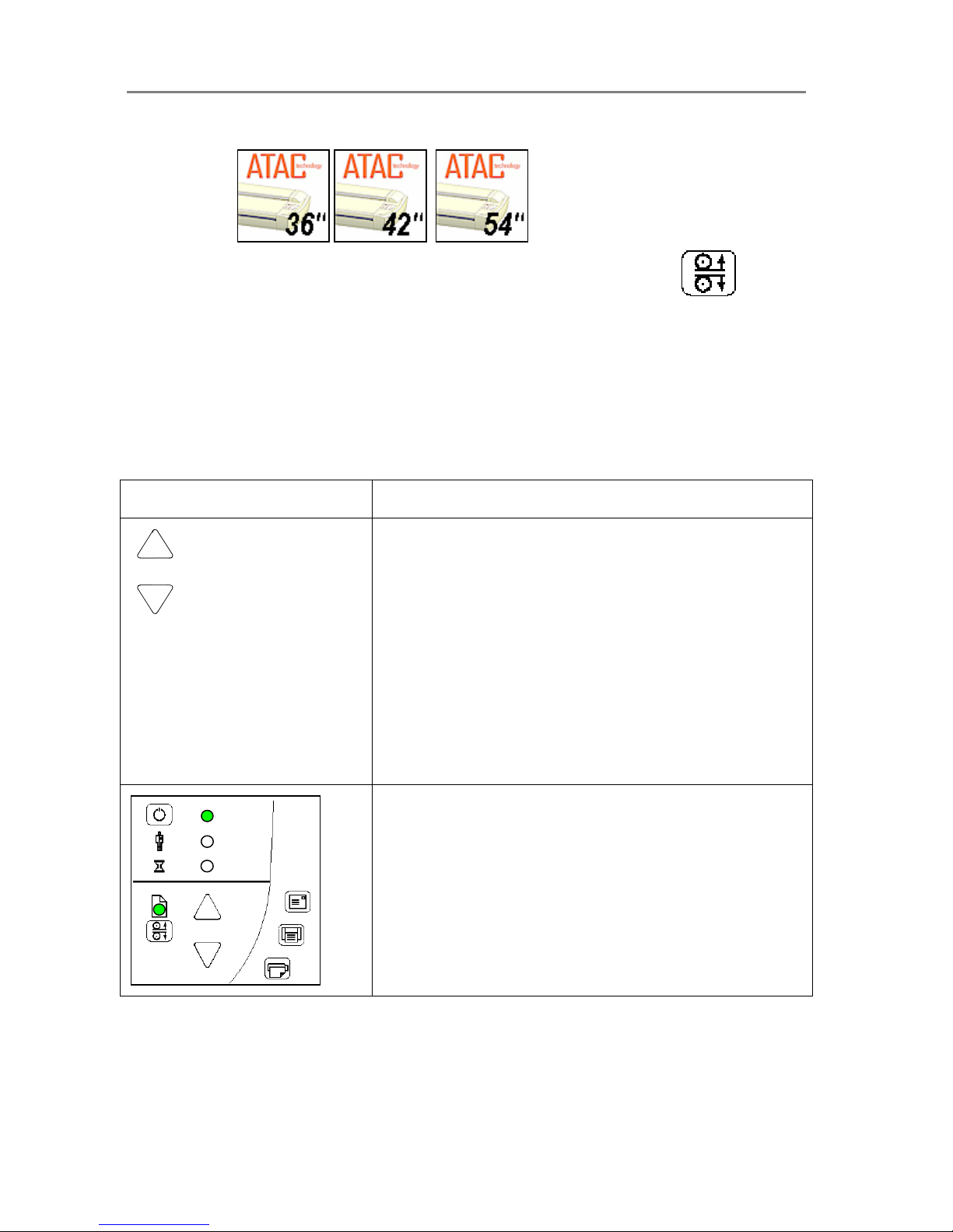
Media Control
On Scanners:
Scanners with the Automatic Thickness Adjustment Control (ATAC) key
These scanner models support Automatic Thickness Adjustment Control for easy adjustment of the
pressure-platen level for scanning thick media. Thick media scanning will be described in detail later in this
manual.
For both thin and thick media, the Paper Ready LED lights up when the media is inserted into the original’s
insertion slot and correctly positioned. The media can then be moved into the start-scan position by
pressing the Paper Forward Key or through automatic loading. The Paper Ready LED will blink during
scanning.
How it looks on scanner…
What it means….
Paper Forward and Paper Reverse Keys
The Paper Forward Key moves the drawing into the start-scan
position for manual loading (see section on Loading).
If Auto-Load is applied, loading will occur automatically (without
pressing the key) when the original enters the insertion slot.
Pressing the Paper Forward Key during scanning will stop the
scanning process and feed the original through the scanner while
the key is held down.
The Paper Reverse Key stops the current scanning process and
reverses the original. The original will be fed backwards through
the scanner while the key is held down.
When the scanner is in Automatic Thickness Adjustment Control
(ATAC) mode the paper forward and paper reverse keys become
“pressure-platen up” and “pressure-platen Down” keys (see below).
Paper Ready LED Green - Ready for Normal media
The Paper Ready LED lights green when normal thin media is
positioned correctly in the insertion slot and stays green when the
media is moved to the start-scan position.
From there, scanning can be controlled from the computer.
Page 30
Scanner Operation - Panel and Indicators 4-12
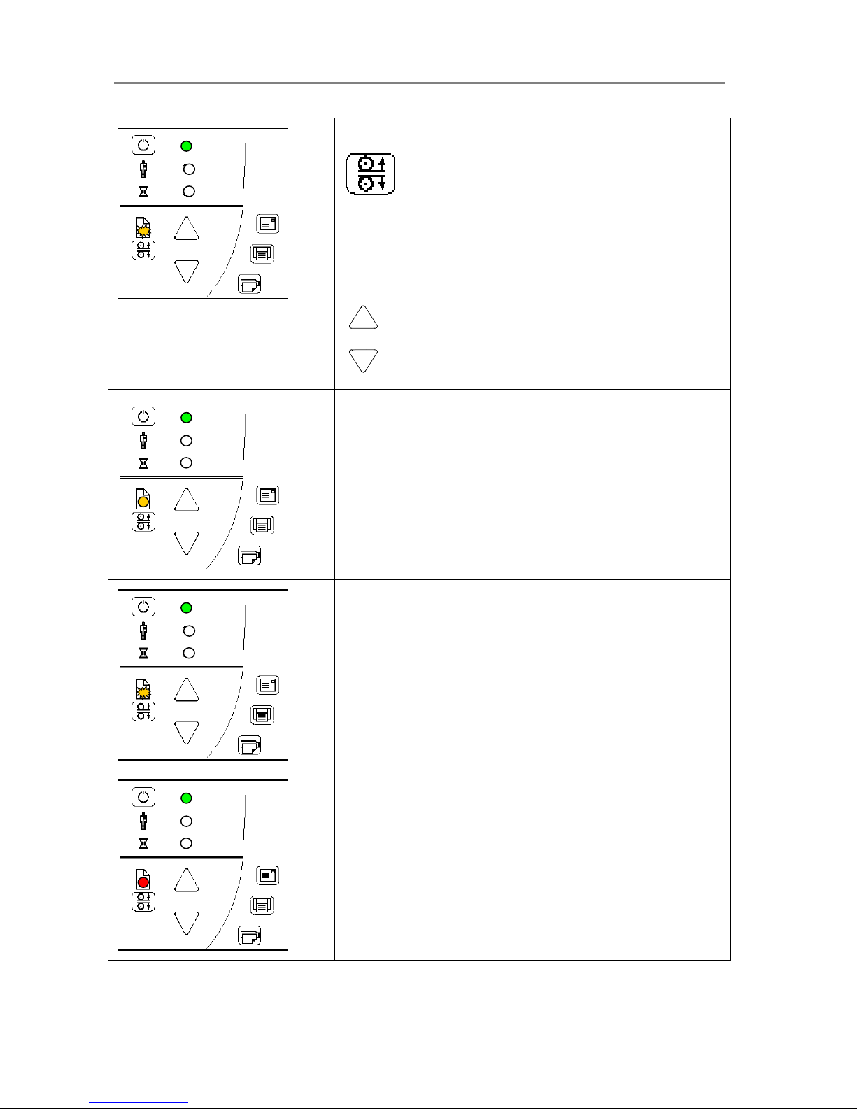
Paper Ready LED Flashes Yellow – Scanner in ATAC mode
ATAC key
When you press the ATAC key, you set the scanner in ATAC
mode. The Paper Ready Key flashes yellow to indicate ATAC
mode.
The Paper Forward and Paper Reverse keys become “Pressureplaten Up” and “Pressure-platen Down” keys.
Paper Forward and Paper reverse Keys become Up/Down keys
Paper Ready LED Yellow - Ready for Thick media
The Paper Ready LED lights yellow when the scanner is ready to
scan thick media. The pressure-platen has been lowered and the
media is positioned correctly in the scanner.
The scanner goes automatically out of ATAC mode. The Paper
Forward and Paper Reverse keys resume their normal functionality
so you can move the thick original forwards and backwards in the
scanner.
Scanning can be controlled from the computer.
Paper Ready LED Flashes – (green or yellow) – Media is being
scanned
The Paper Ready LED blinks during scanning.
On completion of the scan, the Paper Ready LED will stop blinking.
Scanning can then be repeated from the computer or terminated
by ejecting the media from the scanner.
The above behavior applies for both thin media scanning (green
blinking) and thick media scanning (yellow blinking).
Paper Ready LED Red – No Thick media detected
The paper ready indicator will light red if the pressure-platen is in a
thick media setting (a raised pressure-platen) but no media is
detected in the scanner.
Page 31
Scanner Operation - Panel and Indicators 4-13
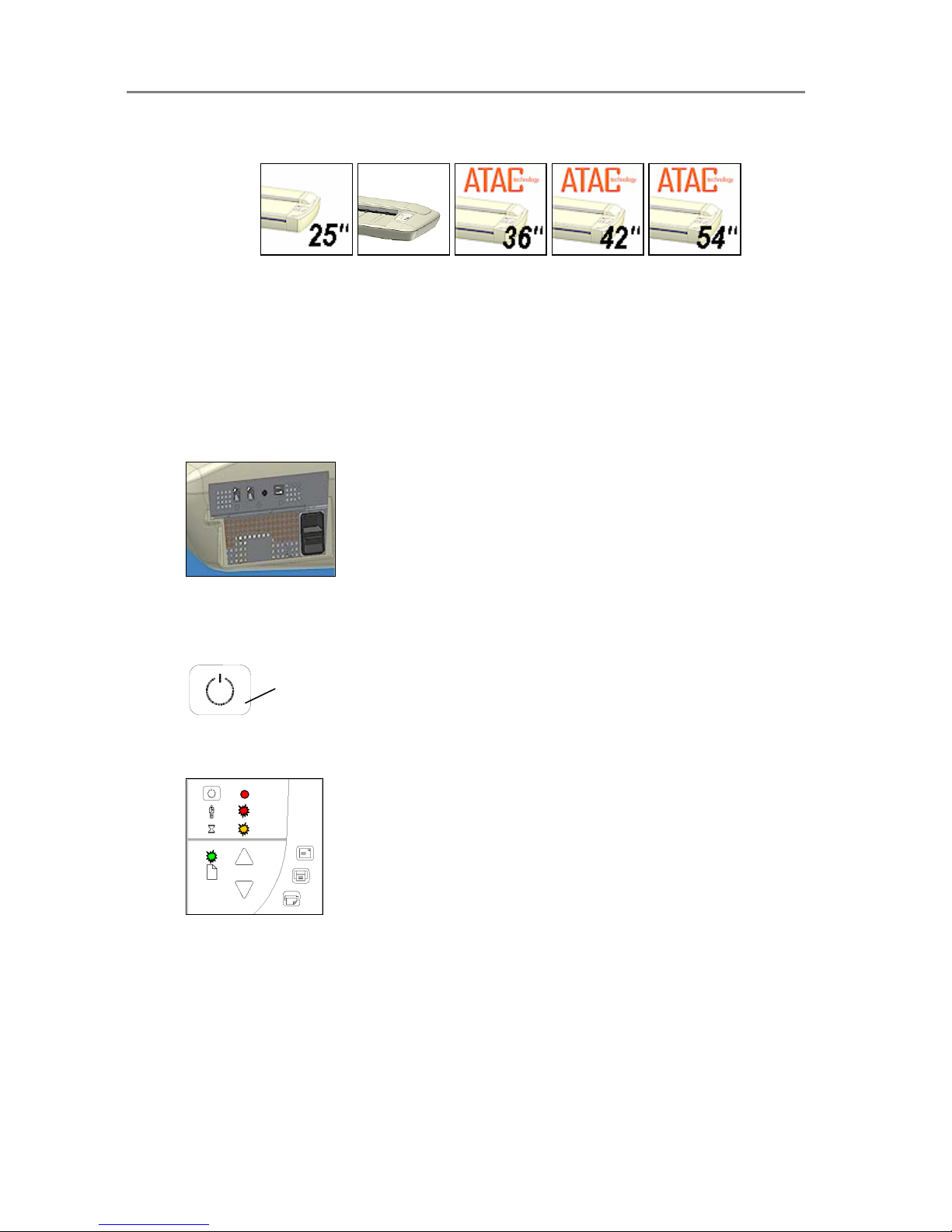
4.5 Setting the Scanner in Firmware BOOT Mode
On All Scanners
You can force the scanner to firmware boot mode. This is useful if an error or power-failure
occurred during a firmware update and you need to restart the firmware update process. A
scanner will not run correctly after an interrupted firmware update process.
To force the scanner to firmware boot mode:
1. If restarting after a power-failure interrupted your firmware update, the scanner should
start up in boot mode. If not, you can use the following panel function to force the
scanner into boot mode.
2. Turn the scanner power off with the outlet switch at the back – Hard Power Off.
3. Press and hold down the Power key on the operator’s panel.
4. As you hold down the power key, reach to its back and Hard Power On the scanner by
flipping on the outlet switch at the back of the scanner.
Invoke Firmware Boot Mode - Press and hold
down the Power Key as you Hard Power On.
5. When the Power LED turns red and the other LEDs flash as shown below, the scanner
is in Firmware Boot mode and you can reapply the Firmware.
Page 32
Scanner Operation - Panel and Indicators 4-14
4.6 Automatic Power functions
On All Scanners
You can set the scanner for automatic power OFF (Sleep) and power ON (Wake-up). Automatic
power management functionality is set and controlled through the WIDEsystem software. There
are two automatic power functions - the Timer function and the Enter Sleep mode
automatically setting. Automatic power management lets you schedule your scanner’s up-time
optimally and helps save energy. The Sleep mode, on ENERGY STAR
®
compliant scanners,
meets the low values of ENERGY STAR
®
criteria.
In order to use automatic power management functionality: the scanner must be Hard
Powered ON – i.e the switch at the scanner’s back must always be ON.
With the scanner Hard Powered On, the scanner can be brought into Wake-up and Sleep
modes manually - by pressing the panel’s power button or by using the automatic power
management functions – Timer and Enter Sleep mode automatically (after idle time). The
power LED on the operator’s panel will light red when the scanner is powered OFF (Sleep) and
green when powered ON (Wake-up).
Power OFF
Power ON
4.7 Energy Star®
On All Scanners
ENERGY STAR
®
is a program helping businesses and individuals protect the environment
through superior energy efficiency. ENERGY STAR
®
qualified scanners automatically enter a
low-power "sleep" mode after a period of inactivity. Spending a large portion of time in lowpower mode not only saves energy but helps scanner equipment run cooler and last longer.
These scanners support an Enter Sleep mode automatically functionality in addition to the
Timer function described in the next section.
Both automatic power management functions (Timer and Idle Time), on ENERGY STAR
®
compliant scanners, reach the low power values that meet ENERGY STAR
®
criteria.
Page 33

Scanner Operation - Panel and Indicators 4-15
4.8 Timer Function - Automatic wake-up/sleep modes
On All Scanners
To best explain usage of the Timer automatic power function, please look at the following
example:
Your business opens a bit later on Mondays then on other days, so you want the scanner to
power on (wake-up) at 07:30 so that by the time you reach work at 08:00, the scanner will be
warmed up and ready to run at an optimal internal temperature. On Tuesday you need to
process a heavy copy order and anticipate a long day. You therefore set the scanner to shut
down (sleep) much later than usual. On Wednesdays, you are always attending meetings and
won’t need the scanner until after lunch. Thursday and Friday are normal workdays and the
shop is closed during the weekend.
You can program this whole weekly schedule into the scanner and rid yourself of worries about
getting early to work in order to warm up your equipment. Nor do you have to worry about
remembering to shut off the device before going home to save energy. Once you fill out the
timer values in WIDEsystem’s Timer tab, the scanner takes care of these things itself.
To use the Timer function:
1. Double-click on the scanner icon in the system tray to display the WIDEsystem interface.
2. Select the Timer Tab.
3. Click the checkmark fields for each day you want automatic wake-up and sleep actions.
4. Click on the 2 hour digits in the day’s edit field under the Wake-up column to highlight it.
Use the arrow box to increase or decrease the hour value.
5. Click on the 2 minute digits in the day’s edit field under the Wake-up column to highlight it.
Use the arrow box to increase or decrease the minute value.
6. Repeat this process in the Sleep column for the same week-day.
7. Continue making settings for the other week-days in the same manner or….
8. You can use the Link Monday to Friday option to make your settings for Monday apply for
the whole work-day-week.
9. Note that the Idle time before sleep time setting will still apply and may conflict with your
Timer settings. Change the Idle time before sleep time setting if it does.
10. When you have filled out the dialog, press Apply to download your settings into the
scanner’s memory.
After making your Timer settings:
1. Your scanner will remember your settings even after you turn off your PC and thereby
shutdown the WIDEsystem application. The settings displayed in the WIDEsystem Timer
tab are retrieved from the scanner every time you start WIDEsystem. This means that the
Timer tab always displays the values currently stored in the scanner.
2. When WIDEsystem runs, it checks that the scanner’s clock is within 2 minutes from the PC
clock. If not, WIDEsystem will synchronize clocks. Normally this only happens when the
Page 34
Scanner Operation - Panel and Indicators 4-16
scanner’s central power switch has been turned OFF manually and its clock needs to be
reset.
3. If the scanner is in use then the scanner will delay Sleep mode. Just before automatic Sleep
mode with the timer occurs, the power LED on the panel will flash. You can cancel Sleep
mode by pressing the power button.
4. Note that the Idle time before sleep time setting will still apply and may conflict with your
Timer settings. Change the Idle time before sleep time setting if it does.
4.9 Idle Time before sleep time
On Scanners:
These scanners support an Idle time before sleep time functionality in addition to the Timer
function described in the previous section. The Idle time before sleep time functionality is an
ENERGY STAR
®
compliant feature.
NOTE: On delivery, your scanner was set to comply with the ENERGY STAR
®
environmental
guidelines with entry into power down mode after being idle for 15 minutes. When you start the
scanner the first time, you are offered the option to change this. If you chose to keep the default
settings at that opportunity, you can at any later time change the settings by following the
instructions below:
To change the Idle time before sleep time (minutes) value…:
1. Double-click on the scanner icon in the system tray to display the WIDEsystem interface.
2. Select the Timer Tab.
3. Select or Deselect the Enter Sleep mode automatically option in the Timer tab dialog.
4. If you selected the option, use the arrows to select the Idle time before sleep time value –
the number of minutes the scanner can stand idle before powering down on its own.
5. Press Apply to download your settings into the scanner’s memory.
Page 35
Loading 5-1
5. Loading Originals into the Scanner
5.1 Center-loading
On All Scanners
The scanner is loaded from the center. Align the center of the document with the center arrow
marking on the scanner top. Use the standard size markings to help align the document for a
straight scan path.
5.2 Manual-loading and Auto-loading
On All Scanners
You can use manual loading or automatic loading. The loading options are selected in the
scanning application.
With manual loading you determine when the scanner pulls in the original:
1. Position the original in center or side according to your setting.
2. Push the original into the insertion slot until you feel it contact the rollers.
3. The Paper Ready LED lights green (yellow for thick media) when the original is
positioned correctly for a straight scan path.
4. While holding the original in place with one hand, use the other hand to press and hold
down the Paper Forward button on the scanner.
5. The original moves into the start-scan position.
With automatic loading, the scanner takes the original as soon as you insert it in the paper
slot. Automatic loading is reliable for most jobs and especially useful for batch scanning jobs.
1. Position the original in center or side according to your setting.
2. Push the original into the insertion slot until you feel it contact the rollers.
3. The Paper Ready LED lights green (yellow for thick media) when the original is
positioned correctly for a straight scan path.
4. The scanner will grab the original automatically and move it into start-scan position.
5. A delay factor can be set in the scanning application. The delay will give you time to
control straight positioning if the scanner is grabbing the original too fast.
Page 36
Loading 5-2
5.3 Fast-loading
On All Scanners
Fast-loading is a time-saving loading option designed for batch scanning. The fast-loading
option can be selected in the scanning application.
What is Fast-loading? – With normal (default) loading, i.e. without the Fast-load option
selected, the original is pulled all the way into the drive system, past both roller axles, and then
reversed to start-scan position in order to ensure precise detection of the original’s placement in
the scanner. With the Fast-load option selected, the original is pulled only under the first roller
axle and scanning will start from there. The Fast-load option is convenient for batch scanning of
originals with robust edges that feed easily. Normally, with batch scanning, you would use the
Fast-load option in conjunction with automatic loading however you can also use manual
loading to feed the original into start-scan position.
5.4 Soft-handling
On All Scanners
Your device is designed to scan at very high speeds for maximum efficiency. However, some
old, curled or creased originals can trigger a paper jam when fed and scanned at high speeds.
You may also have a fragile original that you want passed delicately through the drive system.
The Soft-handling option can be selected in the scanning application. With the Soft-handling
option selected, both feeding and scanning are slowed down to enable smooth scanning of
curled, creased, frayed or fragile originals. You can use the option with Manual, Auto or Fast
loading.
Use this option when:
You received a Paper Jam error
1. A Paper jam error has occurred when the scanner stops scanning and the PaperReady key shuts OFF (from blinking) while the original is still engaged in the drive
system. Your scanning application and WIDEsystem’s Status tab will report the Paper
Jam error.
2. Remove the original from the scanner. Use the Paper-Back or Paper-Forward keys. If
the original does not respond, remove the pressure-platen as described under the
section Maintenance – Cleaning and take the original out of the scanning area.
3. Select the Soft-handling option.
4. Feed the document again to scan.
You have a fragile original
1. Select the Soft-handling option.
2. Feed the original normally.
Page 37
Loading 5-3
5.5 Loading Fragile Originals
On Scanners:
On these scanners, gentle-feed control lets you protect very fragile documents by manually
engaging the document into the drive system without feeding its edges into the rollers.
1. Raise the scanning area lid.
2. The rollers will lift and open the drive pinch.
3. Position your fragile document with the top edge past the backmost rollers.
4. Close the scanning area lid. The document will then be safely engaged in the drive
system.
Loading fragile originals:
On All Scanners
Through your scanning application, you can set the scanner to feed and scan at a slower
speed. See the previous section describing the Soft-handling option.
5.6 Pressure Weights – fine-adjusting for optimal pressure
On Scanners:
On these scanners you can fine-adjust the pressure-platen’s pressure on the original. You can
add or remove one or more of the pressure-platen’s loose pressure-weight-strips to give the
specific original optimal contact with the glass-plate. This is useful when scanning originals that
are either stiff or fragile.
To apply/remove weights:
1. Open the scanning area lid.
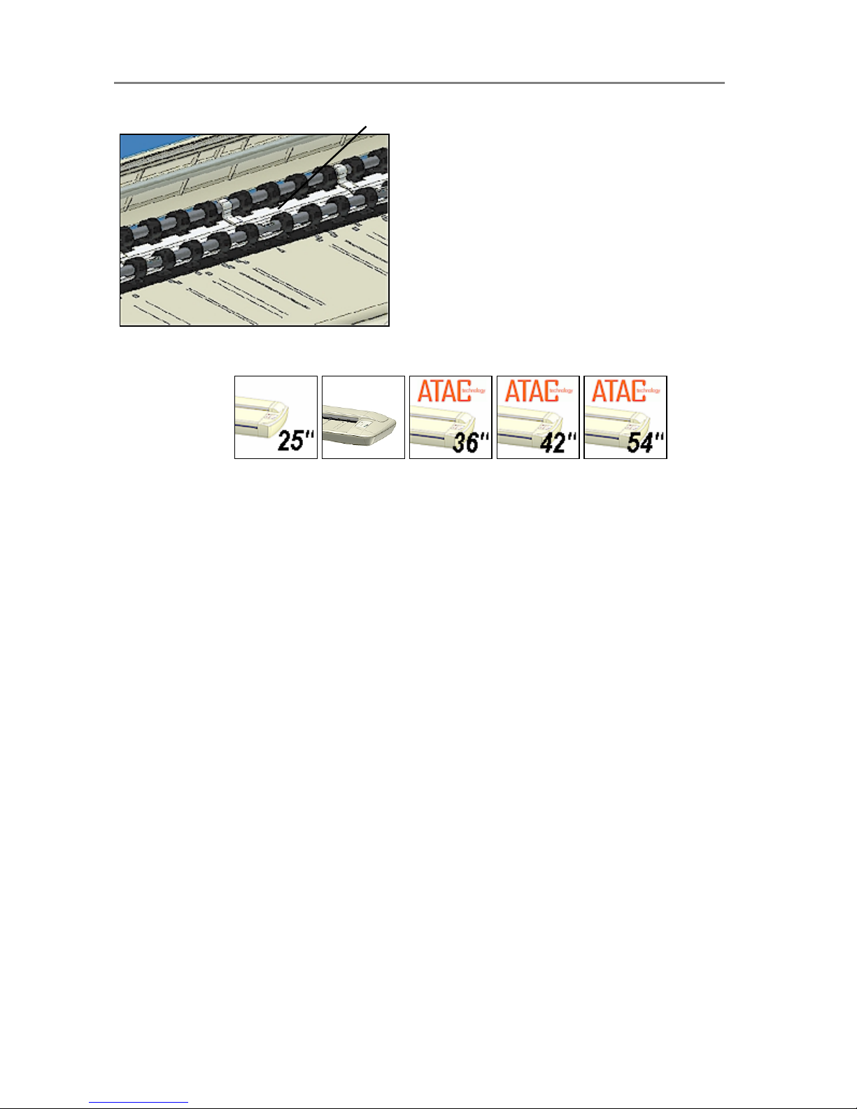
2. The pressure-weight-strips rest on the white pressure-platen.
3. To stabilize the weights on the pressure-platen, fit the holes in the pressure-weightstrips into the pins on top of the platen.
4. Normal weight for most original types is applied with 2 pressure-weight-strips.
5. Remove 1 or both pressure-weight-strips for thin fragile originals.
6. Add 1 or 2 additional pressure-weight-strips for stiff originals.
Page 38
Loading 5-4
Weight strips rest on the top of the pressure platen.
5.7 Size Settings
On All Scanners
Common standard sizes are marked on the scanner topside. Use these markings to guide you
when positioning standard sized originals in the center of the scanner. Enter the size in your
application’s media size setup dialogs
For irregular sizes, you can use the scanner’s measurement ruler just above the insertion slot.
The width of an original can thereby be measured on the scanner. Read the width and enter
your measurement in the width setting box in your application’s media size setup dialogs. The
original is always loaded from the center.
Page 39

Scanning Thick Media 6-1
6. Scanning Thick Media
Many industries, such as reprographics and GIS, will find the need to digitize or copy images
printed or pasted on thick media such as cardboard, foamboards, gatorboards etc. To support
such needs you can change the vertical size of the insertion slot (pressure-platen height) on
your scanner to fit the slot to the thickness of your original. Depending on your scanner model,
adjusting the pressure-platen’s height is either a manual or automatic process.
6.1 Adjustment for Thick Media – Slider Controls
On Scanners:
You can manually change the insertion slot size (pressure-platen height) on your scanner from
2mm to 15mm (up to 0.6”) so you can fit the slot to the thickness of your original. Originals up to
2mm thick should be scanned with the Normal (2mm) setting. Thicker originals will require
adjustment for thick media.
Adjusting the insertion slot for thick media – Normal Method – For all original types:
1. Measure the thickness of your original to find the right setting.
2. Insert your fingers in the insertion slot and lift to open the scanning area lid.
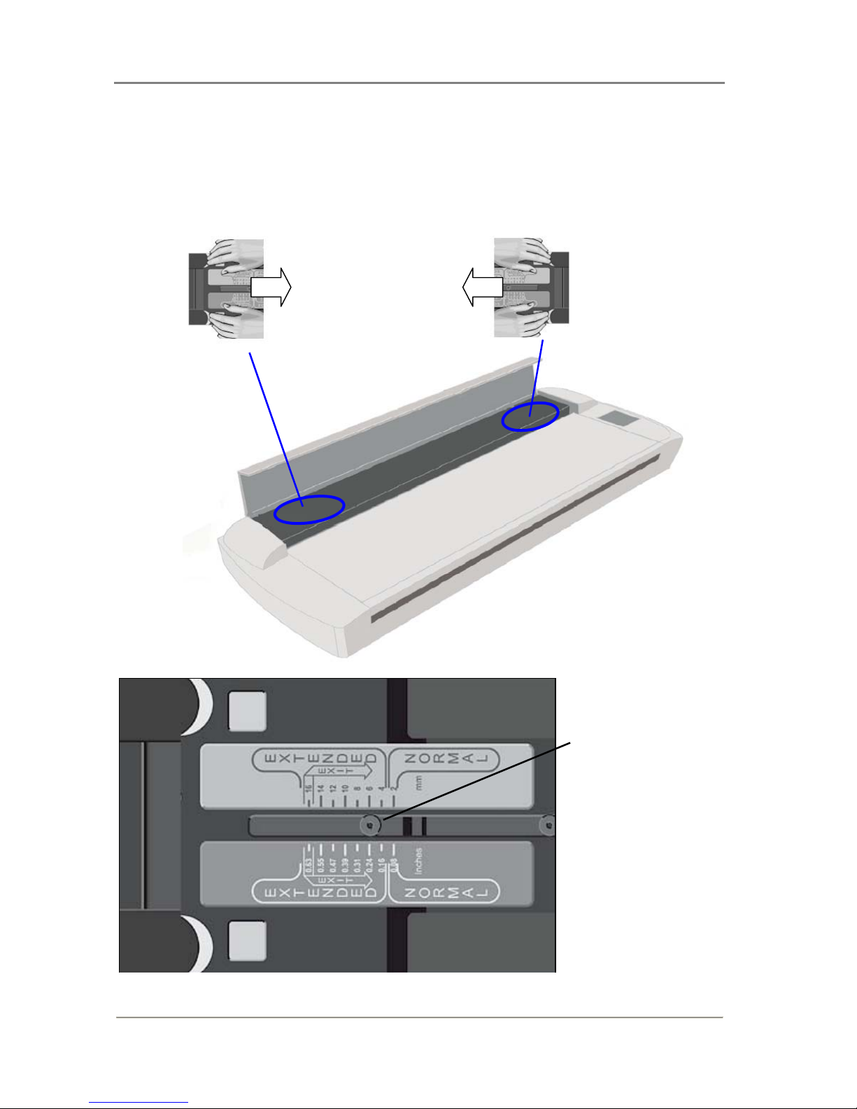
3. The thickness adjustment sliders are on right and left sides of the pressure-platen.
4. The slider is divided into a Normal position and Extended positions.
5. The Extended settings are marked in inches and millimeters. Each step marks an
interval, i.e., the 4 setting means documents from 2mm to 4mm etcetera.
6. The round metal button indicates the current setting (see illustration below). For paper
thin originals this will be on the 2mm (0.08”) setting – also called the “Normal” setting.
7. Press down on the right slider and move inwards (towards middle of scanner) to the
correct thickness setting.
8. Press down on the left slider and move to the same thickness setting as above.
9. Close the scanning area lid.
10. Feed your thick original. The Paper Ready key will turn yellow (stop blinking) when the
pressure-platen is positioned correctly and is ready to scan your thick original.
Quick method –for stiff and thick originals only:
You can use the following Quick method for stiff and hard surface originals. This method is not
recommended for soft or flexible media such as originals mounted on foam boards, as there is a
high risk for creating an over-tight insertion slot and causing damage to the original.
1. Insert your fingers in the insertion slot and lift to open the scanning area lid.
2. The thickness adjustment sliders are on right and left sides of the pressure-platen.
3. Press down on the right slider and move inwards (towards middle of scanner) to the
highest setting, the 16mm (0.63”) mark thickness setting. Repeat with the left slider.
4. Slide the original into the insertion slot and under the pressure-platen.
5. With both hands, press down gently on each side of the pressure-platen until you feel it
contacts the original underneath and the sliders adjust themselves to the proper height.
6. Be sure to control that both sliders (on each side) are set to the same thickness value. If
not, adjust the sliders so they are.
7. The Paper Ready key will turn yellow (stop blinking) when the pressure-platen is
positioned correctly and is ready for thick media scanning.
Page 40
Scanning Thick Media 6-2
Thickness Adjustments Sliders – Normal Method for all original types:
1. The sliders are on each side of the scanner.
2. Place both hands on a slider, push down and move the slider towards the scanner’s middle while maintaining
pressure.
3. Move to the correct thickness setting.
4. Be sure to set the sliders to the same setting on each side of the scanner.
Thickness Adjustment
Slider
In this example, the
button position shows the
slider set for an original
that is 6mm. (0.24”) thick.
Page 41
Scanning Thick Media 6-3
6.2 Adjustment for Thick Media – Lever Controls
On Scanners:
On this scanner model you can adjust the insertion slot size (guide plate height) from 3 to 12
mm (up to 0.47”) using adjustment levers at each side of the scanner. Originals up to 3mm thick
should be scanned with the 3mm (lowest) lever setting. Thicker originals will require you adjust
the lever settings for thick media.
Adjusting the insertion slot for thick media - lever controls
1. Raise the scanning area lid.
2. The thickness adjustment levers are found on the scanner’s right and left sides.
3. Measure the thickness of your original to find the right setting.
4. The lever’s numbered settings represent millimeters.
5. Be sure to set to the same thickness value on both sides.
6. For stiff originals, apply pressure-weight-strips if necessary. See the section on Loading
for instructions.
7. Close the scanning area lid.
8. Feed your thick original The Paper Ready key will turn yellow (stop blinking) when the
pressure-platen is positioned correctly and is ready to scan your thick original.
Thickness Adjustment Lever – (Right Side)
Page 42
Scanning Thick Media 6-4
6.3 Automatic Thickness Adjustment Control
On Scanners:
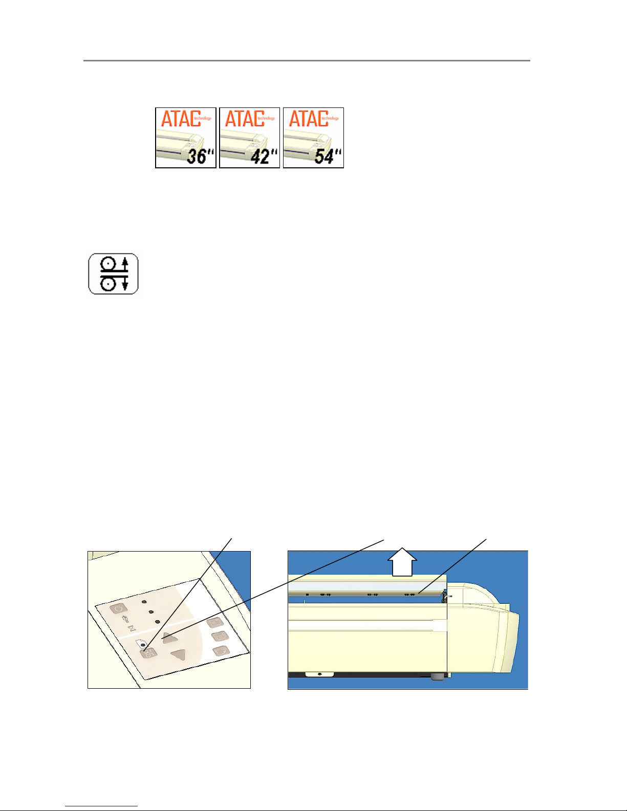
Scanners supporting Automatic Thickness Adjustment Control (ATAC) have an ATAC key on
the operator’s panel. You use the key to raise and lower the pressure-platen. You can change
the insertion slot size (pressure-platen height) on your scanner from 2mm to 15 mm (up to 0.6”).
Originals up to 2mm thick should be scanned with the pressure all the way down (normal
position). Thicker originals will require you use the ATAC key to adjust for thick media.
The ATAC key is on the operator panel.
Adjusting the insertion slot for thick media with ATAC:
1. Press the ATAC key on your operator’s panel to set the scanner in ATAC mode.
2. The Paper Ready Indicator blinks yellow indicating the scanner is in ATAC mode but
not yet ready, i.e., the pressure-platen is not yet positioned on the thick original.
3. Press and hold the Paper Forward key (arrow up) key to raise the pressure-platen until
there is room to insert the thick original.
4. Insert the thick original evenly for a straight scan path.
5. Press and hold the Paper Reverse (arrow down) key to lower the pressure-platen until
the pressure-platen stops on its own.
6. The Paper Ready indicator will turn yellow (stop blinking) when the pressure-platen is
positioned correctly and is ready for thick media scanning.
7. The scanner will automatically leave the ATAC mode, which means that the Paper
Forward and Paper Reverse keys will return to their normal functionality for moving the
original forwards and backwards.
Press the ATAC key on your operator’s
panel to set the scanner in ATAC mo d e.
Pressure Platen in UPposition
- Press and hold the
Pape
r
Forward
key (arrow up) key to raise the pressure-platen.
Page 43

Scanning Thick Media 6-5
6.4 When Scanning in Thick Media Positions
On All Scanners
For Auto-adjustment – return to the Normal position.
The scanner employs an automatic self-adjustment procedure (light profile, stitching etc.) that
can only auto-activate when the scanner is in the Normal position. With prolonged scanning in
extended thickness settings, you should from time to time return the scanner to its Normal
position to allow it to self-adjust. This will ensure refreshed self-adjustment and optimal
performance of your scanner. Make a habit of always setting the scanner in the Normal position
when shutting down, so it can auto-adjust the next time you turn it ON
NOTE:The scanner runs at its optimal speed in the Normal position. To allow stable drive
handling, scanning speed is automatically reduced when the scanner is in the extended
thickness positions.
Modifying Stitching Parameters
Thick stiff originals will rest on top of the scanner rollers and thus raise a small distance over the
glass-plate. This can lead to irregularities in the stitching of images at points between the
cameras (overlapping pixels). In such cases, the stitching parameters will need to be modified.
You can modify stitching parameters through your scanning application.
1. Insert your thick original in the scanner and scan the image using your scanning
application.
2. Check the result in the viewer for overlapping or missing pixels in the camera transition
areas.
3. Adjust the stitching values in the application’s scanner setup dialogs.
4. Repeat scanning and adjustment until the effect is minimized.
Treating Edge Distortion
Scanning thick originals can give distortions when the front edge meets the exit rollers or the
trailing edge leaves the entry rollers. To omit this, the leading and trailing edges are by default
skipped when in an extended thickness position.
Leading/trailing edge skipping can be turned off through the scanning application’s setup
dialogs.
Supporting Thick Originals
Center-loading is the best method for loading thick originals. Its also important to help support
the original during scanning - both at the entrance side and the exit side of the scanner.
Specially designed support tables can be attached to the back of the scanner. Such a table is
recommended for high volume thick media scanning. Ask your local dealer for purchase
information.
Page 44

Maintenance 7-1
7. Maintenance
7.1 Regular Scanner Maintenance
Regular scanner maintenance is a sure way to minimize costly downtime. The three routine
maintenance procedures cleaning, camera alignment and calibration will improve image
quality and reduce your service costs.
The three maintenance functions are closely entwined and they should all be performed in a
single maintenance session, starting with cleaning the scan area and ending with calibration.
The reason for this is simple. If you clean the glass or adjust the cameras then you will have
changed conditions in the scanning area and will need to calibrate in order to readjust black,
white and color interpretation. This works the other way as well – scanner calibration must
always be preceded by cleaning and camera alignment to get reliable calibration results.
Scanner Maintenance is very easy to perform and most of it is completely automatic. After
manually cleaning the scan area, you just insert a Calibration Sheet, start the Scanner
Maintenance program and let the wizard take over as it performs camera alignment and
calibration.
The tools for scanner maintenance were supplied with your scanner - including the program that
will check your scanner and guide you through the maintenance steps. Be sure to install the
Scanner Maintenance program from the WIDEsystem TOOLS CD-ROM. For best results, run
the maintenance procedures right after setting up your scanner for the first time.
7.2 Cleaning the Scan Area
A clean scan area is vital for optimal results.
In order to access the scan area for cleaning or other maintenance purposes, you have to free
the pressure-platen. On some scanner models, the pressure-platen is completely detached
from the scanner. On scanners with Automatic Thickness Adjustment Control (ATAC), the
pressure-platen is fixed inside the scanning area lid and you just have to open it. Cleaning
instructions for each scanner type follow below:
Caution: do not use abrasives, acetone, benzene or fluids that contain these chemicals.
Do not spray liquids directly onto the scanner glass-plate or anywhere else in the scanner.
Caution: Before cleaning the scan area, be sure to turn the scanner power off and
disconnect the power plug.
NOTE: be sure to also clean the scanner’s flat surface so dirt and dust are not dragged into the
scan area with the original.
Page 45

Maintenance 7-2
Cleaning the Scan Area
On Scanners:
1.
Turn the scanner power off and disconnect the power plug.
2. Place your fingers in the insertion slot and flip open the scanning area lid.
3. Press down on the extended media thickness adjustment slider on the right side of the
pressure-platen.
4. While maintaining pressure, slide the right extended media thickness adjustment slider
towards the middle of the pressure-platen (see illustration below).
5. Push the slider all the way until the metal safety button under the slider pops up (see
illustration below).
6. Repeat the process on the left side.
7. Make sure the platen is completely free.
8. On the topside of the pressure-platen are one or two hinged handles. Flip up the
handles and use them to lift out the pressure-platen (see illustration below).
9. The glass-plate is now exposed for cleaning. Clean the glass with a lint-free cloth and a
mild, streak-free, glass cleaner. Dry the glass completely using a separate clean, dry
lint-free cloth like the one provided with the maintenance kit.
10. The white-background-platen is on the backside of the pressure-platen you just
removed. Flip the pressure-platen over to clean the white background.
11. Wipe the white area and the transport rollers with a lint-free cloth and a mild, streakfree, glass cleaner. Apply the cleaner to the cloth and first wipe the platen’s white area
and then the transport roller’s surface.
12. Dry the pressure-platen and rollers completely using separate clean, dry lint-free cloths.
13. Reverse the above procedure to reinsert the pressure-platen. On each end, you will
need to press down the metal button before you can move the slider back from the Exit
position.
14. Clean also the scanner surface so dirt and dust are not dragged into the scan area with
the original.
15. Cover your scanner with the plastic dust cover when not in use.
Caution: Make sure the scanner power is OFF when using the scanner dust cover.
Page 46
Maintenance 7-3
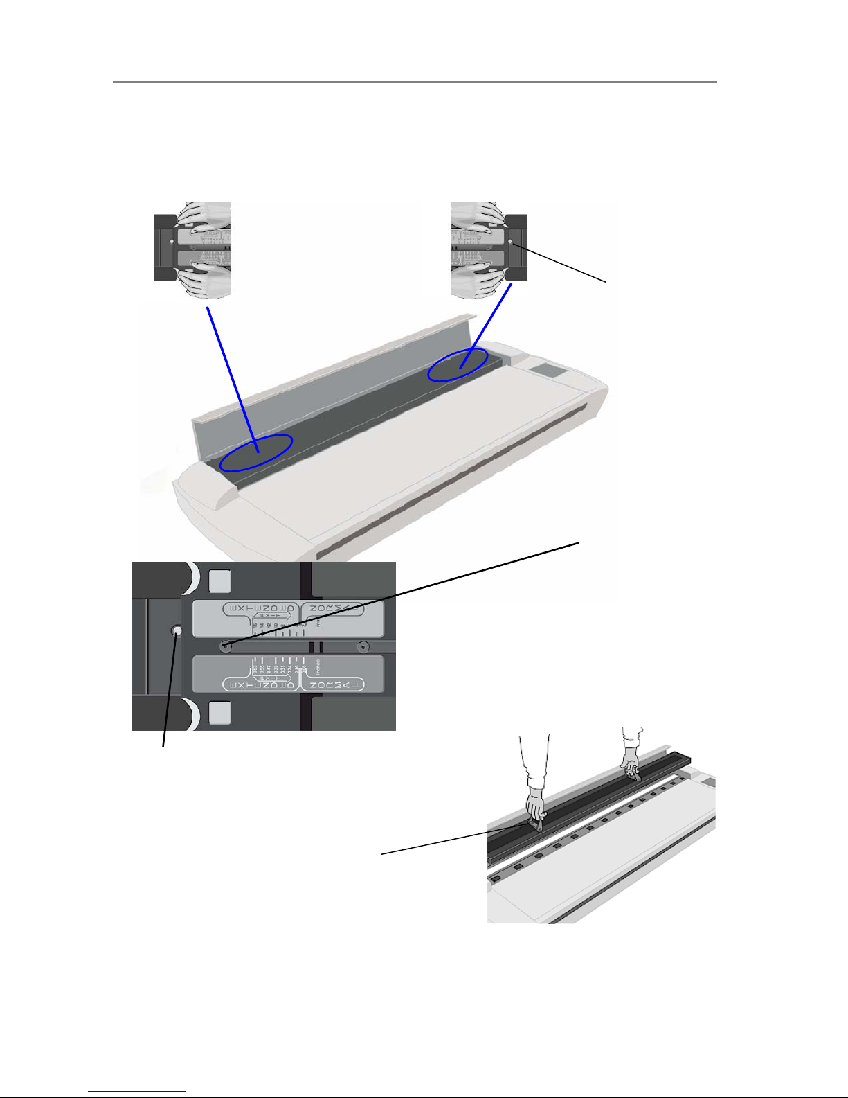
Cleaning – To access the scan area - Move the sliders to the exit position and free the pressure-platen
1. The extended media thickness adjustment sliders are on each side of the scanner.
2. Place both hands on a slider - push down and move the slider all the way towards the scanner’s middle
while maintaining pressure until the metal button pops up.
3. Repeat this on both left and right side sliders to free the pressure-platen.
The metal button
pops up when the
slider is in the Exit
position.
Exit position :
The slider is pushed all
the way towards the
scanner’s middle.
The metal button pops up.
Flip up the handles and use them to lift out the pressureplaten. Clean the exposed glass and the whitebackground-platen on the backside of the
pressure-platen.
Page 47
Maintenance 7-4
Cleaning the Scan Area
On Scanners:
1.
Turn the scanner power off and disconnect the power plug.
2. Place your fingers in the insertion slot and flip open the scanning area lid.
3. The drive system automatically lifts up.
4. Grasp the white pressure-platen on its back edge braces. Tip up the back edge of the
pressure-platen and lift it out to expose the glass-plate underneath.
5. Clean the glass with a lint-free cloth and a mild, streak-free, glass cleaner. Dry the
glass completely using a separate clean, dry lint-free cloth like the one provided with
the maintenance kit.
6. On this scanner, the pressure-platen’s backside also serves as the white background.
Wipe the white backside of the pressure-platen and the transport rollers with a lint-free
cloth and a mild, streak-free, cleaner.
7. Dry the pressure-platen and rollers completely using separate clean, dry lint-free cloths.
8. Reinsert the pressure-platen. First place the pressure-platens front braces so they rest
on the front drive axle.
9. Tip the platen backwards until the pressure-platen’s back braces rest on the backmost
drive axle.
10. Close the scanning area lid.
11. Clean also the scanner surface so dirt and dust are not dragged into the scan area with
the original.
12. Cover your scanner with the plastic dust cover when not in use.
Caution: Make sure the scanner power is OFF when using the scanner dust cover.
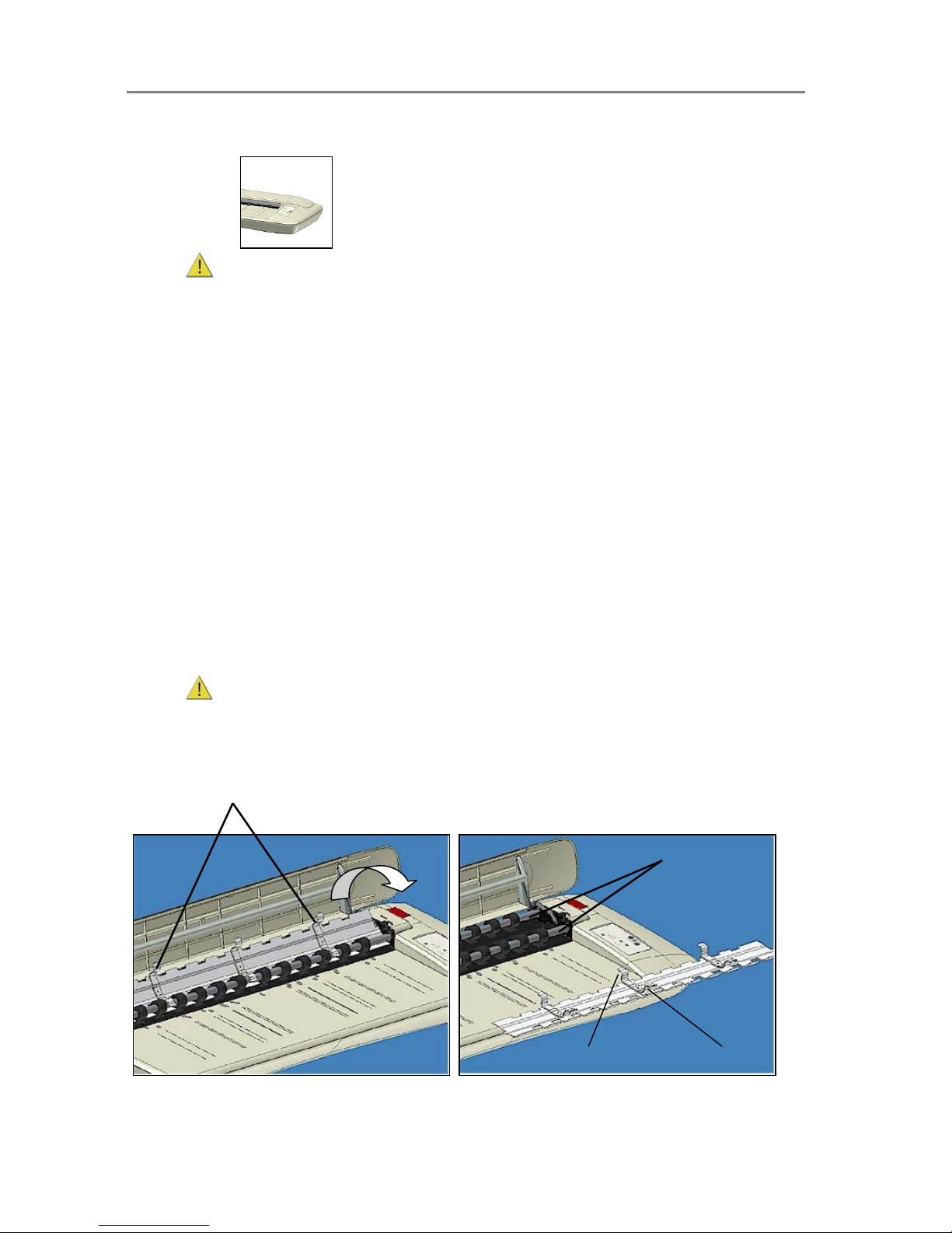
To remove the pressure-platen
Grasp by the braces on the pressure-platen’s backside
edge.
Flip up the back edge and lift out the pressure-platen.
When you reinsert the pressure-platen: position so
the braces rest on the parallel drive axels.
Drive Axles
Cleaning – To access the scan area – remove the pressure-platen
Front brace.
Back brace.
Page 48
Maintenance 7-5
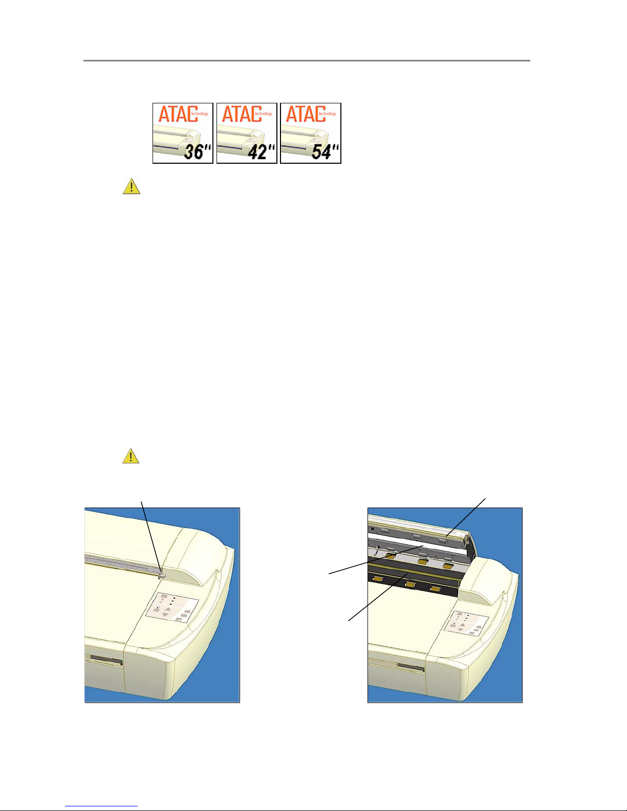
Cleaning the Scan Area
On Scanners
1.
Turn the scanner power off and disconnect the power plug.
2. Push down on the two lever buttons found near the insertion slot on each side of the
scanning area lid.
3. The scanning area lid locking mechanism should now be disengaged.
4. As you hold both lever buttons down, place your free fingers in the insertion slot and flip
the scanning area lid open.
5. The glass-plate is now exposed for cleaning.
6. Clean the glass with a lint-free cloth and a mild, streak-free, glass cleaner. Dry the
glass completely using a separate clean, dry lint-free cloth like the one provided with
the maintenance kit.
7. The pressure-platen with the white-background-platen (white metal area) is fixed in the
scanning area lid. Hold the lid open as you clean.
8. Wipe the white area and the transport rollers with a lint-free cloth and a mild, streakfree, glass cleaner. Apply the cleaner to the cloth and first wipe the platen’s white area
and then the transport roller’s surface.
9. Dry the platen and rollers completely using separate clean, dry lint-free cloths.
10. Close the scanning area lid when finished. The locks will reengage.
11. Clean also the scanner surface so dirt and dust are not dragged into the scan area with
the original.
12. Cover your scanner with the plastic dust cover when not in use.
Caution: Make sure the scanner power is OFF when using the scanner dust cover.
Push down lever (on both sides) to
unlock scannin
g
area lid.
While holding down the levers, insert fingers in the slot and flip
the lid open to access the gl ass-plate and white-backgroundplaten.
Glass-plate
Whitebackgroundplaten
Page 49
Maintenance 7-6
7.3 Running the Scanner Maintenance Program
On All Scanners
For optimal results, you should always run the Scanner Maintenance program after
cleaning.
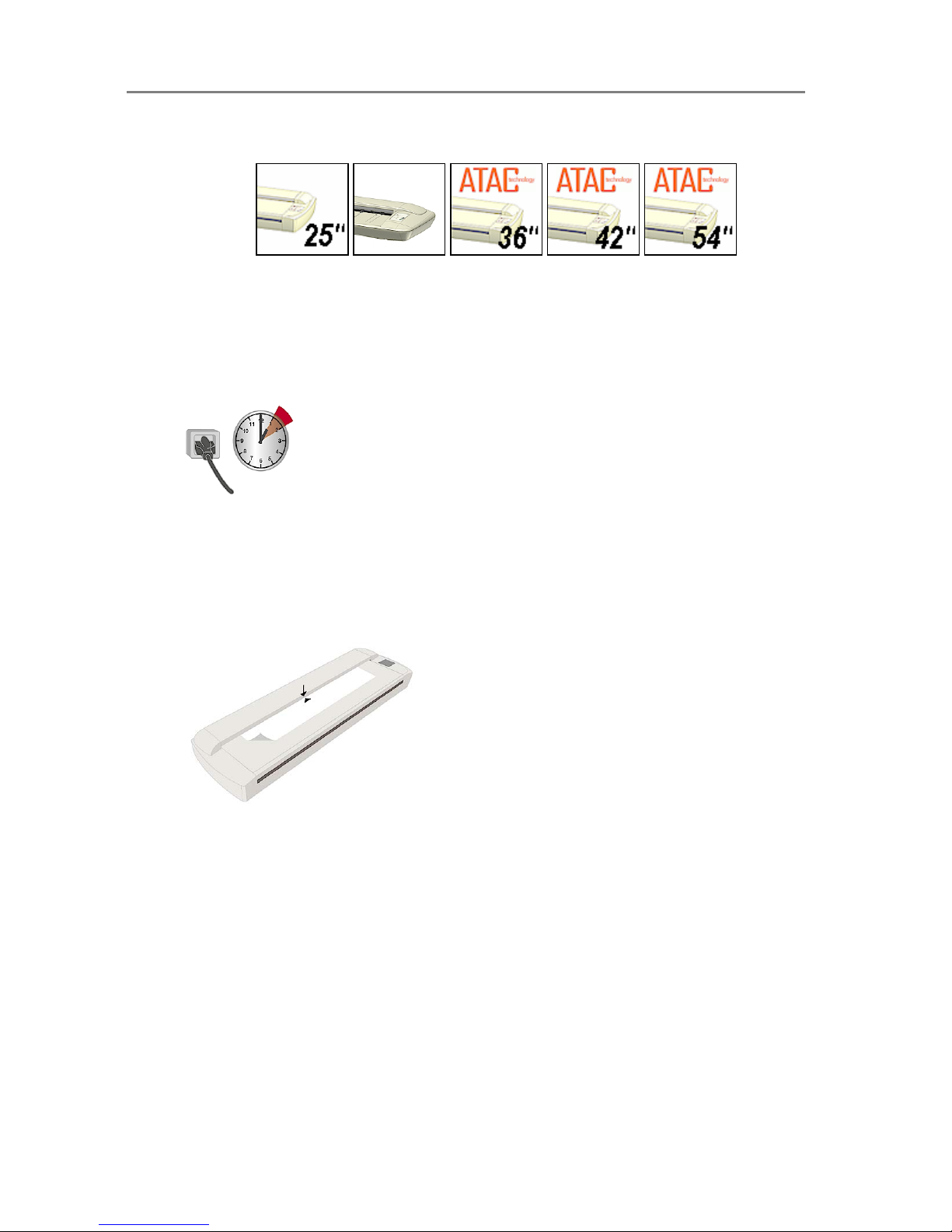
1. Make sure that the scanner has been turned on for at least one hour prior to camera
alignment and calibration. Slight light intensity changes and camera shifting can occur
just after turning the scanner on and the warm-up time will ensure that light conditions
and camera heights have stabilized.
2. On your PC, Select
Programs > Scanner Maintenance to start the Scanner
Maintenance Wizard.
3. The wizard will guide you through the maintenance steps - Camera Alignment, Stitching
and Calibration. Click the
Next button in the welcome dialog to proceed.
4. The wizard will ask you to insert the Calibration Sheet that came with your scanner.
The
sheet’s printed side must be inserted face down
. Align the midpoint arrow with the
scanner’s midpoint arrow and feed the sheet into the scanner. Click
Next to continue.
Inserting the Maintenance Sheet
A
lign the midpoint arrow with the scanner’s midpoint
mark and feed the sheet into the scanner.
5. The program immediately analyses
alignment and stitching status of the cameras. If
the cameras are unaligned, the program and scanner will automatically make the
necessary corrections. This step will be bypassed on single camera scanner models.
6. After Camera Alignment, the Scanner Maintenance program automatically moves on to
Basic Calibration. Basic Calibration sets black/white values and ensures stable and
clean scans by reducing noise and unwanted effects caused by dust particles.
7. On color scanners, the program automatically proceeds to
Color Calibration. Color
Calibration uses the ANSI IT8 standards to ensure stable and predictable colors every
time.
8. Calibration completes the maintenance process. Remove the Scanner Calibration
Sheet from the scanner.
9. Return the Scanner Calibration Sheet to its protective cover and then place it in the
storage folder. Store the folder in a dry place and out of direct light.
Page 50
Maintenance 7-7
7.4 Replacing Scanner Parts
This section describes how to replace those scanner parts that are liable to wear down over
long-term use. Changing parts will renew your scanner and ensure optimal results.
WIDEsystem monitors scanner usage and will warn you when it is time for a replacement.
NOTE: For glass plate and White background platen replacement: After receiving a warning by
WIDEsystem and replacing the part, be sure to reset the part replacement warning flag though
WIDEsystem’s “Status” tab.
Some scanner models are designed so users can replace parts on their own (user-replaceable
parts) while other scanner models will require a service technician. The instructions in this
section apply only for scanners with user-replaceable parts.
Scanner Type Parts that are User-Replaceable
No parts user-replaceable - Contact your service technician for
replacing parts.
Glass-plate, White-background-platen, Lamp
Glass-plate, White-background-platen, Lamp, Dust filters
Glass-plate, White-background-platen, Lamp, Dust filters
Glass-plate, White-background-platen, Lamp, Dust filters
Important Safety Instruction: Before replacing any user-replaceable parts, be sure to turn
the scanner power off and disconnect the power plug.
Page 51
Maintenance 7-8
7.4.1 Replacing the Glass-plate
Some scanner models are designed so users can detach the glass-plate from the scanner in
order to replace scratched glass-plates with new ones. On other scanner models, a service
technician must perform this process. See your scanner’s model specifications to see if the
glass-plate is detachable.
Replacing the Glass-plate:
On Scanners:
1. Turn the scanner power off and disconnect the power plug.
2. Place your fingers in the insertion slot and flip open the scanning area lid.
3. The drive system automatically lifts up.
4. Lift out the pressure-platen to expose the glass-plate underneath.
5. On the right side of the glass-plate there is a small round finger-handle.
6. Place your finger under the finger-handle and lift the glass-plate’s right side upwards.
7. As soon as there is space under the glass-plate, use your free hand to grip under the
glass-plate and carefully lift it out of the scanner.
8. Reverse the process to reinsert a new glass-plate. Position the right side of the new
glass-plate in the scanner and let down the right side using the round finger-handle.
9. Reinsert the pressure-platen so its braces rest on the parallel drive axles.
Page 52
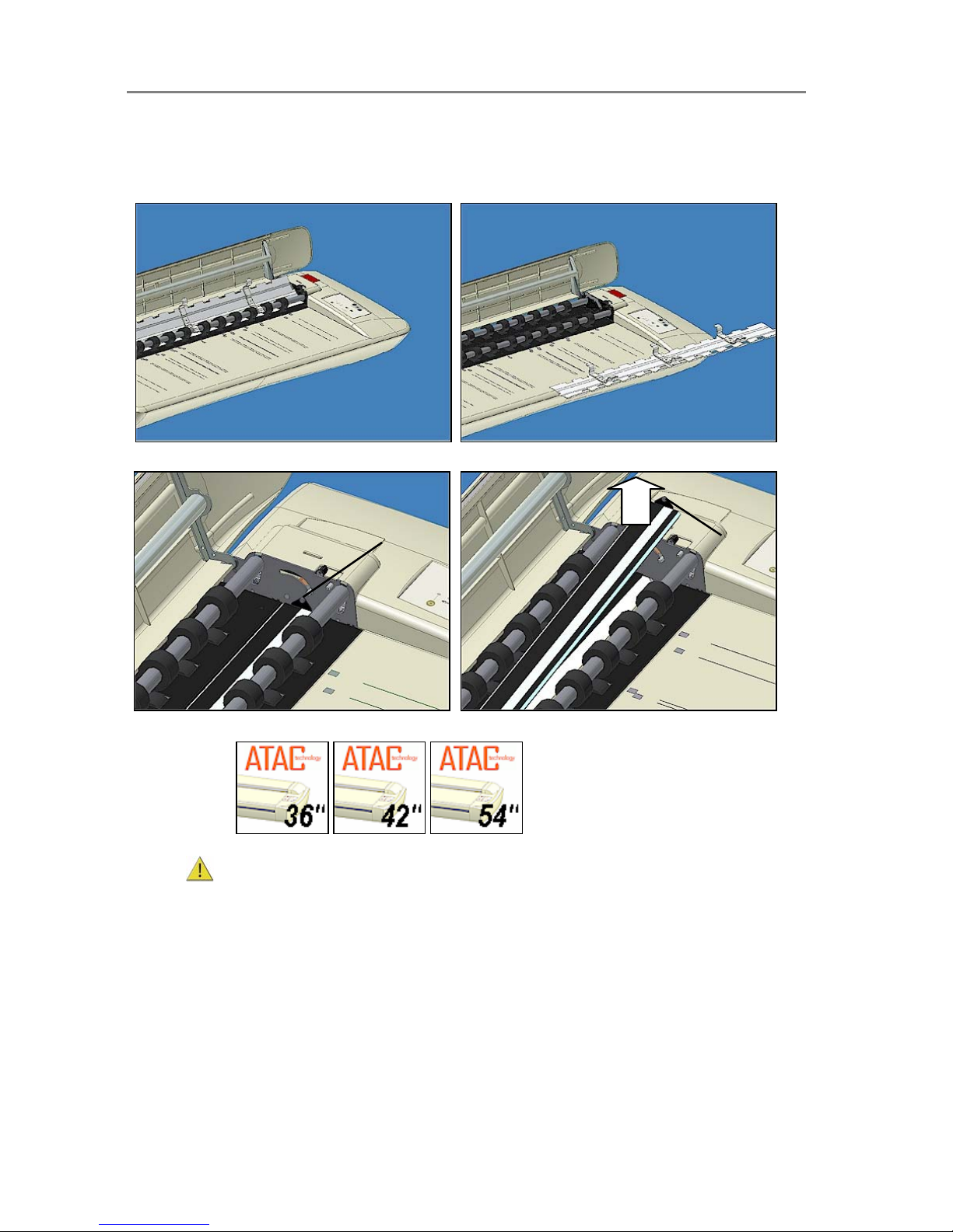
Maintenance 7-9
NOTE: Make sure you clean a new glass-plate before using it with the scanner.
NOTE: Be sure to reset the part replacement warning flag though WIDEsystem’s “Status” tab.
To Remove the glass-plate
Step 1: Open lid and tip up the pressure-platen.
Step 2: Remove the pressure-platen.
Step 3: Locate the small round finger handle on the right
side.
Step 4: With your finger on the round handle, lift the
glass-plate up and grasp under it with your free hand.
Finger-handle
Finger-handle
Replacing the Glass-plate:
On Scanners:
1. Turn the scanner power off and disconnect the power plug.
2. Push down on the two lever buttons found near the insertion slot on each side of the
scanning area lid.
3. The scanning area lid locking mechanism should now be disengaged.
4. As you hold both lever buttons down, place your free fingers in the insertion slot and flip
the scanning area lid open.
5. The glass-plate will be exposed and accessible.
6. On each side of the glass-plate there is a small lever and round finger-handle (see
illustration below). Place your thumbs under both handles on each side.
7. With both arms, pull simultaneously on the left and right levers to flip the glass-plate
towards your body.
Page 53
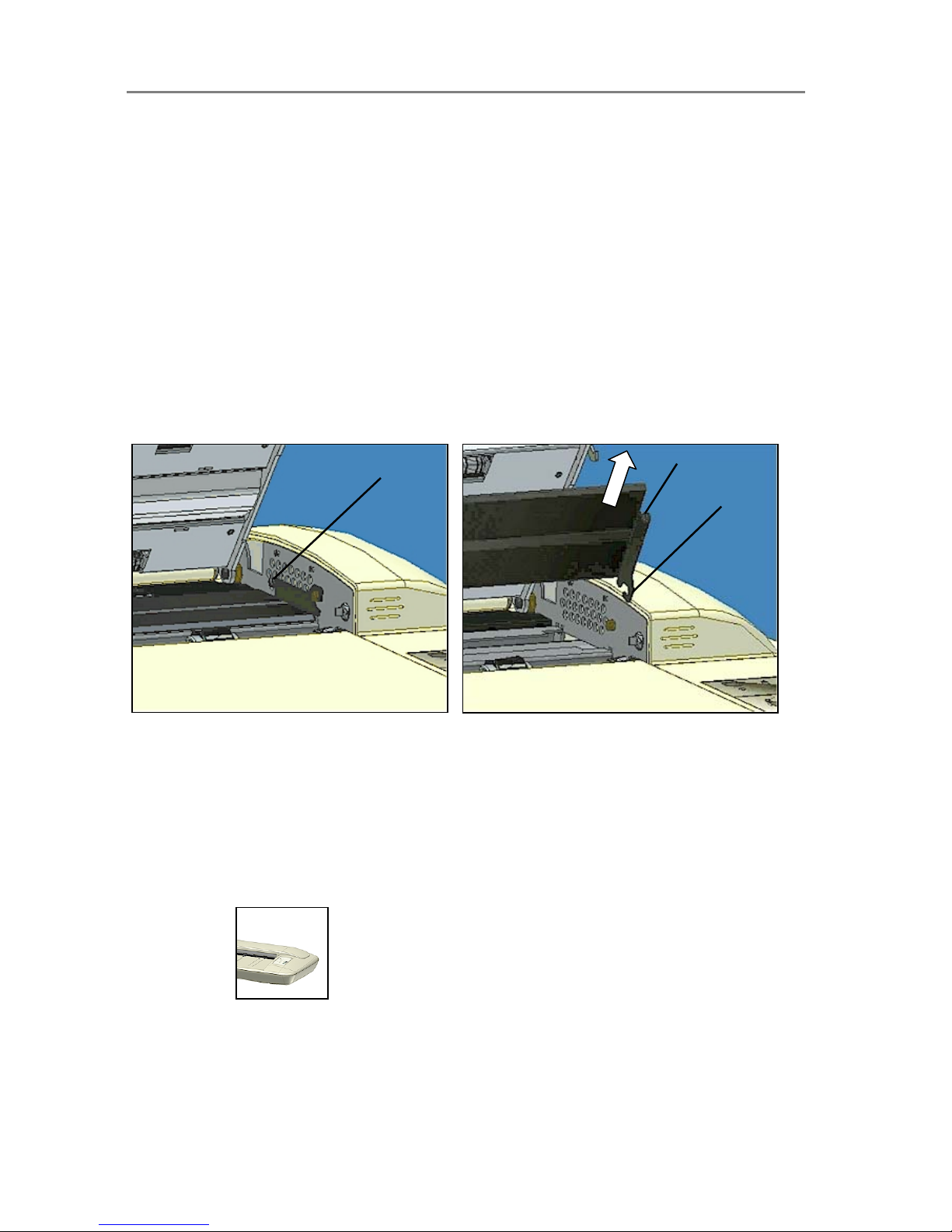
Maintenance 7-10
8. Each lever is attached to the scanner chassis with a small hook that rests on a pin.
Simultaneously lift both levers upwards to detach their hooks for the pins and free the
glass-plate from the scanner.
9. To reinsert a new glass-plate – Fit the new glass-plate’s lever hooks on the pins on
each side of the scanner.
10. While supporting the glass-plate with your thumbs on the finger handles, carefully push
the glass-plate backwards (away from your body) and ease it down into place.
11. Close the scanning area lid.
NOTE
: Make sure you clean a new glass-plate before using it with the scanner.
NOTE: Be sure to reset the part replacement warning flag though WIDEsystem’s “Status” tab.
Remove the glass-plate:
Step 1: Open the lid. Locate the lever’s finger handle on
each side.
Shown below: Right side finger-handle.
Step 2: Flip back. Lift the lever’s hooks and glass-plate
free of the scanner.
Hook
Finger handle
Finger handle
7.4.2 Replacing the White-Background-Platen
Some scanner models are designed so users can replace the white-background-platen. On
other models, a service technician must perform this process. See your scanner’s model
specifications to see if the white background is user-replaceable on your scanner.
A white-background-platen can become worn and discolored after long periods of use and
replacement with a fresh white-background-platen is recommended. WIDEsystem monitors
scanner usage and will warn you when it is time for a replacement.
Replacing the White-background-platen:
On Scanners:
On these scanner models, the pressure-platen itself functions also as the white-backgroundplaten. Replacing the white-background-platen means replacing the scanner’s (white) pressureplaten.
Page 54
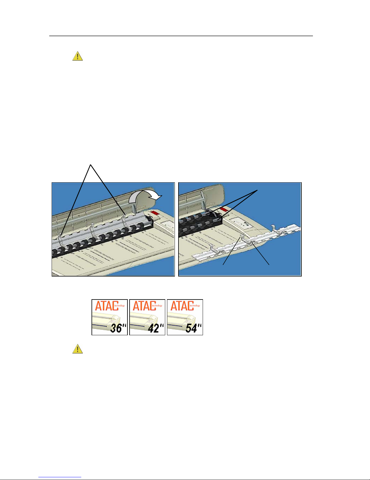
Maintenance 7-11
1.
Turn the scanner power off and disconnect the power plug.
2. Place your fingers in the insertion slot and flip open the scanning area lid.
3. The drive system automatically lifts up.
4. Grasp the white pressure-platen on its braces – back edge. Tip up the back edge of the
pressure-platen and lift it out.
5. Replace with a new pressure-platen. Insert the new pressure-platen. First place the
pressure-platens front braces so they rest on the front drive
axle.
6. Tip the platen backwards until the pressure-platen’s back braces rest on the backmost
drive axle.
7. Close the scanning area lid.
NOTE:
Be sure to reset the part replacement warning flag though WIDEsystem’s “Status” tab.
Grasp by the braces on the pressure platen’s back edge.
Flip up the back edge and lift out the pressureplaten. When you reinsert a new pressure-platen:
position so the braces rest on the parallel drive axels.
Drive Axles
The white background and pressure platen are the same. To remove the pressure-platen:
Front brace.
Back brace.
Replacing the White-background-platen:
On Scanners:
1. Turn the scanner power off and disconnect the power plug.
2. Push down on the two lever buttons found near the insertion slot on each side of the
scanning area lid.
3. The lid’s locking mechanism should now be disengaged.
4. As you hold both lever buttons down, place your free fingers in the insertion slot and flip
the scanning area lid open.
5. On the lid’s left edge, you will find a red strip. Remove the red strip to expose the edge
of the white-background-platen.
6. Grip the edge of the white-background-platen with your fingers and pull to slide it out of
the scanner.
7. Slide in a new white-background-platen.
Page 55
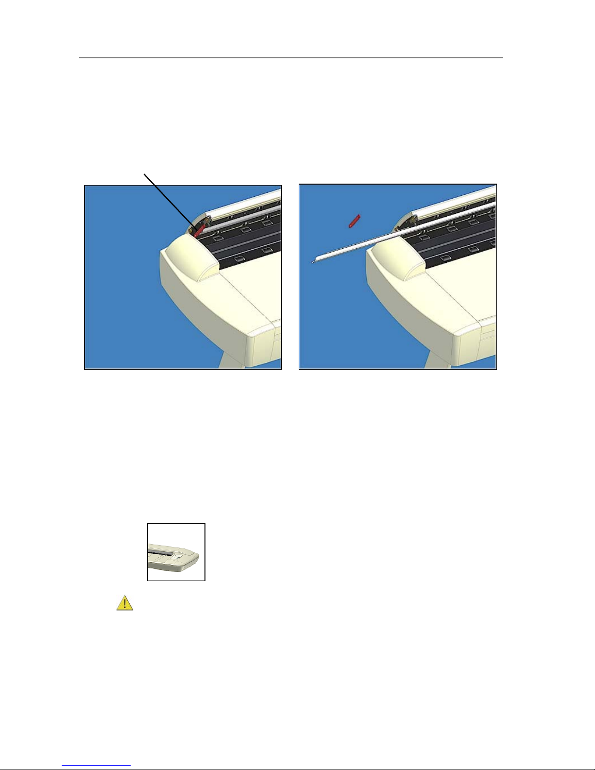
Maintenance 7-12
8. Reattach the red strip.
9. Close the scanning area lid so the locking mechanism reengages.
NOTE:
Be sure to reset the part replacement warning flag though WIDEsystem’s “Status” tab.
To change the white-background-platen:
Open the lid and locate the red strip on the left side
of the scanner.
Remove the strip and slide out the white background
platen. Reinsert a new platen and replace the strip.
7.4.3 Replacing the Scanner Lamp-Unit
Your scanner comes with a high quality and durable lamp. Even so, its effectiveness will
gradually weaken over time. Some scanner models are designed so users can replace the
lamp. On other models, a service technician must perform this process. See your scanner’s
model specifications to see if the lamp is user-replaceable on your scanner.
A new lamp-unit (lamp, reflector, power connectors) for lamp-replaceable scanner models can
be obtained through your dealer. WIDEsystem monitors scanner usage and will warn you when
it is time for a replacement.
Replacing the Scanner Lamp-unit:
On Scanners:
1. Turn the scanner power off and disconnect the power plug.
2. The lamp cover is on the left side of the scanner.
3. Place your fingers under the small handle on the bottom of the cover and hold the top
with your thumb.
4. Lift upwards to release the catch and then flip back to remove the cover.
5. You must replace the whole lamp-unit. A lamp-unit consists of a lamp mounted in a
reflector brace and fixed power connectors.
Page 56
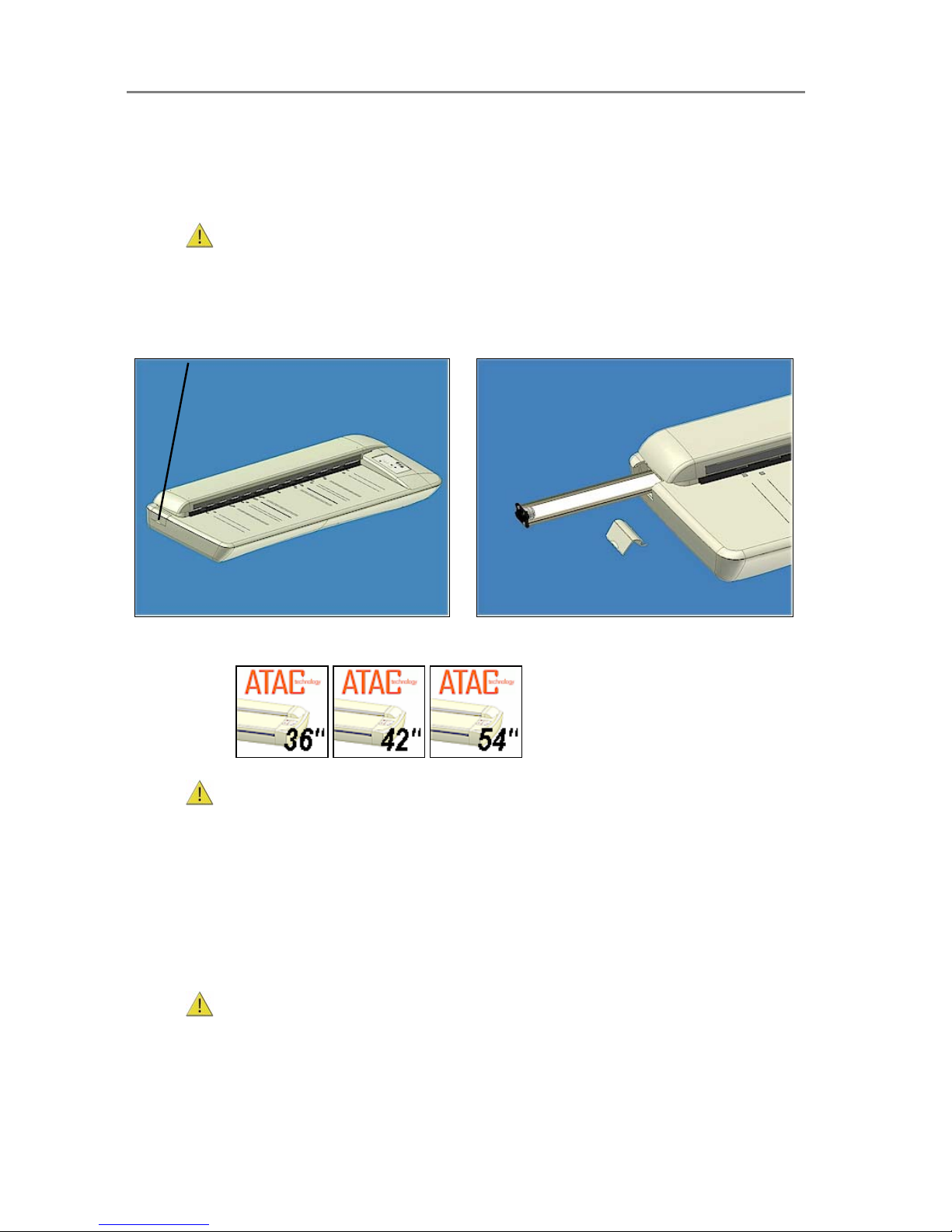
Maintenance 7-13
6. Grasp the edge of the lamp-unit and carefully pull it out of the scanner.
7. Reinsert the new lamp-unit. Rest the power-connector side on the slider and carefully
push the lamp-unit into the scanner.
8. Insert the lamp-unit all the way so the internal power connections engage with the
connections on the lamp-unit.
9.
Replace the lamp cover - fit the hinges in the holes and snap the cover shut. The
cover must always be closed before turning scanner power ON.
10. Test the replacement by turning power on to see if the lamp lights.
To replace the lamp-unit:
Locate the lamp cover on the left side of the
scanner.
Open the lamp cover as described above. Pull out the
lamp-unit and replace with a new one.
Replacing the Scanner Lamp-unit:
On Scanners:
1. Turn the scanner power off and disconnect the power plug.
2. The lamp cover is on the top right edge of the scanner.
3. Grasp the cover on each side with both hands and pull back to detach.
4. Lift the cover upwards to free it from the scanner.
5. You must replace the whole lamp-unit. A lamp-unit consists of a lamp mounted in a
reflector brace and fixed power connectors.
6. Grasp the edge of the lamp-unit and carefully pull it out of the scanner.
7. Reinsert the new lamp-unit. Rest the power-connector side on the slider and carefully
push the lamp-unit into the scanner.
8. Insert the lamp-unit all the way so the internal power connections engage with the
connections on the lamp-unit.
9.
Replace the lamp cover on the scanner - fit the bottom notches in the holes and
snap the cover shut.
The cover must always be closed before turning scanner power
ON.
10. Test the replacement by turning power and scanner on to see if the lamp lights.
Page 57
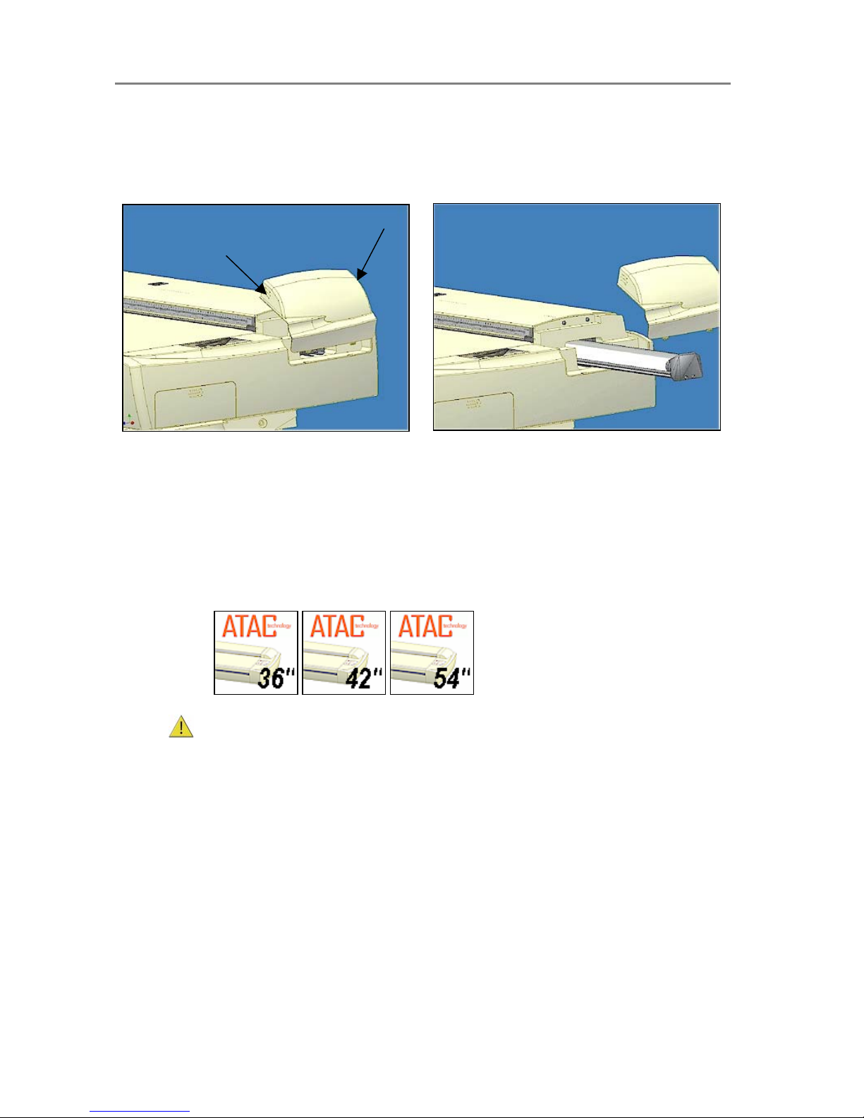
Maintenance 7-14
To replace the lamp-unit:
The lamp cover is on the right side of the scanner.
Grasp the cover on both sides, pull back and then
up to detach.
Free the cover from the scanner. Pull out the lamp-unit
and insert the new one.
7.4.4 Replacing the Dust-Filters
Fresh dust filters can reduce the amount of time spent on cleaning and calibration. The dust
filters protect your scanner’s air-cooling vents. Some scanner models are designed so users
can replace the dust filters. On other models, a service technician must perform this process.
See your scanner’s model specifications to see if the dust filters are user-replaceable on your
scanner. WIDEsystem monitors usage and will warn you when it is time for a replacement.
Replacing the Dust-filters:
On Scanners:
1. Turn the scanner power off and disconnect the power plug.
2. Locate the 2 square-shaped dust filter bins on the underside of the scanner.
3. Pull down on the edge of a dust filter bin to detach it from its frame.
4. The filter (soft material) is inside the bin. Remove the old filter and replace with a fresh
one.
5. Reattach (click on) the bin to its frame on the underside of the scanner.
6. Repeat the process with the second filter.
Page 58
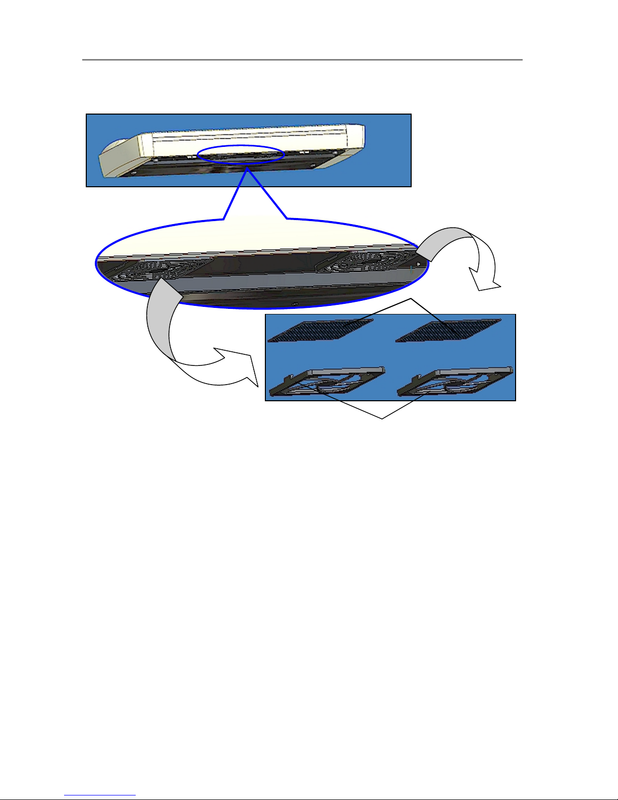
Maintenance 7-15
Changing the Dust-filters:
The filter bins on the underside of the scanner. Pull down on a filter bin’s ed
g
e to detach a filter bin from its frame.
Dust Filter Bins
Filters to change.
Page 59

Maintenance 7-16
7.5 Downloading New Firmware
On All Scanners
Like a computer, your scanner employs processors that require software in order to work. This
software is called "Firmware”. Firmware is the software that runs inside the scanner.
When to use new firmware?
Your scanner is shipped with the latest firmware available. You can afterwards upgrade your
original firmware with newer firmware and continue to do so as they are released. Firmware
upgrades can be downloaded from your manufacture’s website or obtained through your dealer.
Upgrade your firmware when:
1. One or more new features are released or other improvements are made to the
scanner though its firmware.
2. An error is discovered in the firmware version you have in the scanner and your
manufacturer recommends installation of new firmware in which the error is corrected.
Your manufacture’s website specifies improvements for every new firmware release.
How to identify the firmware version running in the scanner?
1. Start WIDEsystem – double click on the system tray’s scanner icon.
2. Select the
Info tab.
3. The Info tab displays useful data about your scanner firmware.
• Firmware release - Upgradeable firmware version.
• Firmware revision - Firmware build number.
• Firmware timestamp - The date/time the current firmware code was compiled.
• Firmware download time - The date/time the current firmware was downloaded.
You can upgrade if the
Firmware Release number is lower than the newest firmware version
number on your manufacture’s website.
How to install new firmware?
New firmware is installed by opening a firmware .exe file. The firmware .exe file must first reside
on your machine. Select the Save target (or Save Link) option if downloading from the web.
To install the firmware file on your scanner:
1. Download/save the firmware .exe file in a folder on your machine.
2. Start WIDEsystem’s Quick menu - Right-click the scanner icon in the system tray.
3. Select
Advanced Options. Select Update Scanner Firmware
4. Browse the folders on your machine and find the firmware .exe file you wish to apply.
5. Select the firmware file and click OK to install. Installation can take up to 1 minute
depending on the scanner model and firmware version. The WIDEsystem scanner icon
on your system tray blinks red during the download process.
6. Follow the instructions on your screen.
7. For recovery of errors during firmware installation, see the section on the
Firmware
Boot mode
.
Page 60
Maintenance 7-17
7.6 Monitoring Your Scanner
On All Scanners
You installed WIDEsystem in order to install the scanner drivers (see this guide’s section on
Installation – Install Drivers and Maintenance Software). WIDEsystem also contains an
application part that monitors the scanner and reports on its functionality. You can access
WIDEsystem directly by clicking on the scanner icon on your Windows system tray.
Double click the system tray’s scanner icon to activate the WIDEsystem control interface.
Here are some of the features obtainable with WIDEsystem:
• Gain visual indication that the scanner is connected to the PC.
• View the scanner’s status, in WIDEsystem called the Scanner Mode, by moving the mouse
over the scanner icon on the system tray. Status messages include remaining warm-up
time, interface connection errors, and an indication that the scanner is ready for scanning.
• View useful Error messages that relate to the actual Scanner Mode. Press F1 to launch the
WIDEsystem on-line help system and find descriptions/instructions on trouble shooting
specific errors displayed.
• View the load status of the original (media) to be scanned.
• Setup the scanner’s timer to determine times for automatic power-up / pow er-down for
each day of the week.
• View information on the scanner device in relation to firmware and hardware revisions. The
information helps you keep track of your upgrades and is useful for support purposes.
• Initiate a scan of the systems hardware bus for re-establishing the interface.
• Quick launch of installed scanning applications.
• Assign/reassign applications to the scanner’s one-touch-scan buttons, or disable the one-
touch-scan buttons altogether.
• Set up your scanner so it can be shared by user PC’s on the network.
• Set up your PC to receive scanned files into a special scan-to-file designated folder.
Note:
Double-click the scanner icon and press F1 to launch the WIDEsystem on-line help system. The
on-line help contains full instructions on using the WIDEsystem program.
Page 61

Trouble Shooting Common Problems 8-1
8. Trouble Shooting Common Problems
This section describes trouble-shooting procedures for the most common problems that can
arise with your scanner. Please look for a problem description that matches your actual
situation. If found, perform the trouble-shooting procedures before requesting a service call.
8.1 Problems Related to Scanner Installation
Problem Possible Causes and Remedies
“Unknown device is found“
message.
1. Your interface is not enabled on the PC or set up correctly. Go through the
installation steps for your interface board and its driver and control that the
Windows device manager lists the interface option.
2. WIDEsystem drivers were not installed before connecting the scanner. Shut
down the scanner and PC, unplug the connections and restart the installation
from step 1 as described above. If you continued installation before installing
WIDEsystem, see the troubleshooting instructions below.
3. Loose interface connection – on both ends, unplug and then firmly plug-in the
interface cable.
4. Smart Card not inserted correctly. Control that the smart card contact side faces
downwards and the card is inserted all the way in its slot.
5. System needs rebooting - shut down the scanner and PC, unplug the
connections. Then plug in the interface connections, turn on the PC and when
Windows is loaded, turn on the scanner.
Need to reinstall.
I got the “Unknown device
is found“ message and
continued installation of the
scanner. Now the scanner
appears as incorrectly
installed on my system.
If you connected and tried to install the scanner before installing WIDEsystem, the
unknown device found message will appear. If you continued to step through the
dialogs from there, the scanner will be entered on the system as a new device without
functional drivers. If this is the case, the scanner will be displayed in the Windows
Device Manager with a yellow error icon. The scanner entry must be removed from
the Device manager before re-installing correctly.
1. In the Device Manager - remove the scanner entry.
2. Shut-down the PC, shut down and unplug the scanner, disconnect the scanner
from the PC.
3. Reboot the PC and install WIDEsystem and Maintenance software
4. Refer to the installation instructions for your interface type in this guide.
WIDEsystem does not
detect the scanner.
1. The WIDEsystem driver version installed on your PC is older than your scanner
model. Install the WIDEsystem drivers form the WIDEsystem TOOLS CD-ROM
that came with your scanner. If not available, download the newest version from
your manufacturer’s website or contact your dealer to obtain the right
WIDEsystem version.
2. WIDEsystem drivers were not installed before connecting the scanner. Shut
down the scanner and PC, unplug the connections and restart the installation
from step 1 as described above.
3. Loose interface connection – on both end, unplug and then firmly plug-in the
interface cable.
4. System needs rebooting - shut down the scanner and PC, unplug the
connections. Then plug in the interface connections, turn on the PC and when
Windows is loaded, turn on the scanner.
Page 62
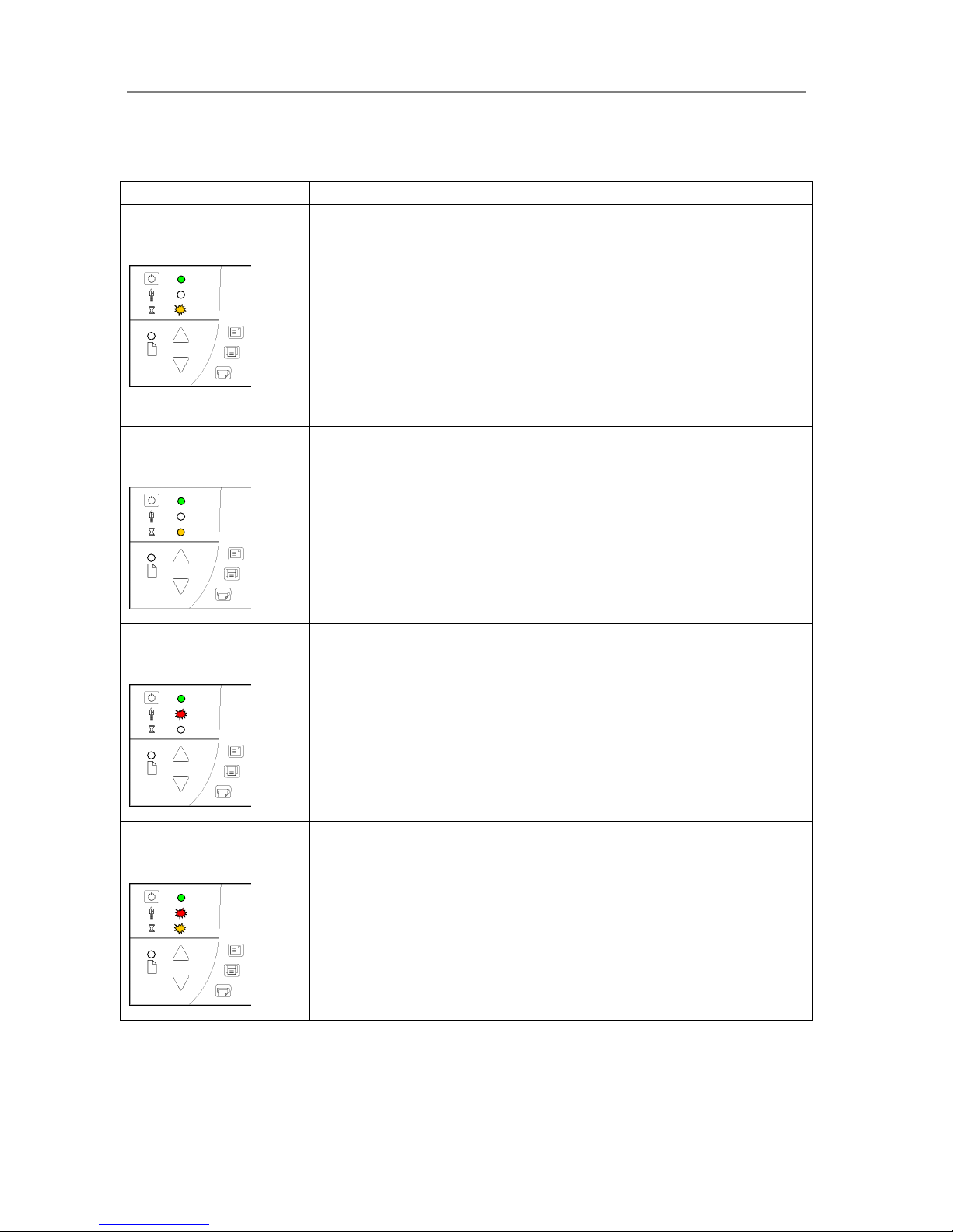
Trouble Shooting Common Problems 8-2
8.2 Problems Related to Operation of the Scanner
Problem Possible Causes and Remedies
Wait light flashes,
diagnostics light is off
1. The scanner needs to run Self-Adjustment but cannot. Self-Adjustment cannot
run with a raised pressure platen or with media in the scanner.
Self-Adjustment is necessary for maintaining optimal and stabile internal
conditions.
Remedy: Any original in the scanner should be removed, and the pressure-platen
should be set to the
Normal position (i.e., not a thick media setting).
2. When Self-Adjustment becomes possible, the Wait LED stops flashing, but
continues to be on until Self-Adjustment is completed.
3. If the error doesn't disappear turn the scanner off and then on.
4. If the error persists, you can reinitialize all settings by unplugging the scanner and
waiting a few minutes before turning power on again.
Wait LED goes on during
calibration
1. This is NORMAL - The Wait LED goes on during Calibration to indicate that the
original should not be removed or moved during the Calibration procedure. All
panel input is prevented during basic calibration
.
Diagnostics LED flashes
1. An Error was detected during the scanner’s Self-Test. Open WIDEsystem
(scanner icon on your system tray) and select the Status tab to view additional
information about the error.
Both wait and diagnostics
LEDs flash
1. The scanning area needs cleaning and the cameras need to be calibrated. Run
through the scanner maintenance steps described in this guide.
2. If the Diagnostic and the Wait LEDs continue to flash after scanner maintenance,
then there may be camera position errors that require help for your technical
service provider.
Page 63
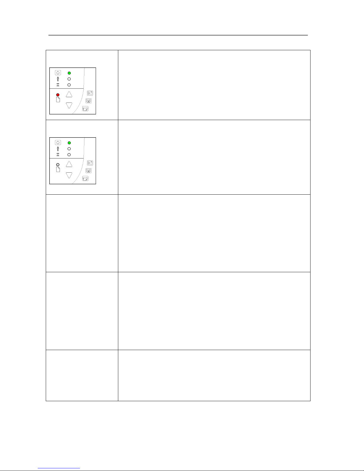
Trouble Shooting Common Problems 8-3
Paper Ready lights RED
1. The pressure-platen is in a thick media setting (a raised pressure-platen) but the
scanner does not detect the media. If you are scanning thick media, insert the
thick media into the scanner.
2. If the problem persists with thick media in the scanner, control that the pressureplaten level is correct. Repeat the steps for correct adjustment for thick media as
described in this guide.
Error message: Paper Jam
1. A Paper jam error has occurred when the scanner stops scanning and the PaperReady key shuts OFF (from blinking) while the original is still engaged in the drive
system. Your scanning application and WIDEsystem’s Status tab will report the
Paper Jam error. Remove the original from the scanner. Use the Paper-Back or
Paper-Forward keys.
2. If the original does not respond to the Paper Forward, Paper-Back keys, remove
the pressure-platen as described under the section
Maintenance – Cleaning and
take the original out of the scanning area.
3. Select the Soft-handling option in your scanning application.
4. Feed the document again to scan.
Error message: Correction
of Camera X (A, B, C, or D..)
failed
1. Your scanner is continuously monitoring its cameras. This error message often
appears when the internal glass plate or white background platen is dirty or
smudged. Clean the scanning area, reboot the scanner and then complete the
maintenance steps (alignment and calibration) as described in the section
Maintenance in this guide.
2. If the problem persists after cleaning the scanner area - The problem could be
caused by a loose object in the optical path. Remove any torn pieces of paper or
other loose objects from the scanning area. Even the smallest loose objects will
disturb the scanner’s adjustment function.
3. Summon your technical service provider if the problem persists.
Error message: Stitching of
Camera X/Y (A/B or B/C or
C/D) failed
1. Your scanner is continuously monitoring its cameras. This error message often
appears when the internal glass plate or white background platen is dirty or
smudged. Clean the scanning area, reboot the scanner and then complete the
maintenance steps (alignment and calibration) as described in the section
Maintenance in this guide.
2. If the problem persists after cleaning the scanner area - The problem could be
caused by a loose object in the optical path. Remove any torn pieces of paper or
other loose objects from the scanning area. Even the smallest loose objects will
disturb the scanner’s adjustment function.
3. Summon your technical service provider if the problem persists.
Error message: Invalid
Smart Card for this scanner
type.
Error message: No Smart
Card found.
1. Control that a Smart Card is in the Smart Card slot. See the section
Smart Card
in this guide for instructions on locating your scanner’s Smart Card slot.
2. Smart Card not inserted correctly. Control that the smart card contact side faces
downwards and the card is inserted all the way in its slot. Shut down scanner
power and restart to initialize with the smart card data.
Page 64

Trouble Shooting Common Problems 8-4
Error message: Unable to
Adjust Camera
1. Control that the scanner is set for
Normal (lowest) media thickness. The
scanner’s pressure-platen must not be raised. Lower the original guide plate on
both sides to let the scanner make its adjustments.
2. If the thickness setting is/was Normal - there could be a loose object in the optical
path. Remove any torn pieces of paper or other loose objects from the scanning
area. Even the smallest loose objects will disturb the scanner’s adjustment
function.
3. If the problem persists after controlling for loose objects in the optical path – the
problem is often caused by an unclean or smudged internal glass plate or white
background platen. Clean the scanning area, reboot the scanner and then
complete the maintenance steps (alignment and calibration) as described in the
section
Maintenance in this guide.
4. If the problem persists after cleaning the scanner area and all above possibilities
have been attempted - summon your technical service provider.
Application control keys
(one touch) do not work
1. Check the One Touch setup entries in WIDEsystem. Click on the scanner icon to
open WIDEsystem and select the
One Touch tab. View WIDEsystem Help for
instructions.
2. Check that the applications defined in the WIDEsystem One Touch setup entries
are installed on your PC
3. Make sure that the applications defined in the WIDEsystem One Touch setup
entries are actually designed to work with (compatible with) your scanner’s
application control keys. See the application’s documentation or contact the
application software dealer.
Can’t operate or contact
scanner after Firmware
upgrade failure.
1. A power failure could interrupt an ongoing firmware upgrade process. The
scanner will not run correctly after an interrupted firmware update process. Only
part of the intended firmware may be loaded, rending the scanner inaccessible.
You need bring the scanner into firmware boot mode to reapply the firmware.
2. Restart the scanner. The scanner should start up in boot mode. If not, you can
use the following panel function to force the scanner into boot mode.
3. Turn the scanner ON so it starts its Init-Sequence (all LEDs on). Towards the end
of Init-Sequence, the Power LED lights green while the other LEDs remain
lighted, signaling that you can interrupt the self-test to force Firmware Boot mode.
You have to activate the boot mode before the scanner moves into selfadjustment. Self-adjustment is started when the Wait LED lights yellow, the
Power LED still lights green and all the other LEDs are off.) To activate boot
mode, press and hold down the Power key.
When the Power LED turns red and the other LEDs flash (see below), the
scanner is in Firmware Boot mode and you can reapply the Firmware.
4. On scanners wih SCSI interface, you can force firmware boot mode by setting the
DIL switch 7 to ON.
Page 65

Trouble Shooting Common Problems 8-5
8.3 Problems Related to the Scanning Results
Problem Possible Causes and Remedies
Not whole image scanned
1. Check in your scanning application that your size settings are either for Auto
detection or correspond to the size of the whole original.
2. Check in your scanning application that you are loading the original correctly in
relation to your choice of Center-loading or Side-loading. If you selected Sideloading in your application then the original must be fed into the side of the
scanner starting from the 0 marking on the top ruler. If Center-loading was
selected in the application then align the center of the original with the scanner’s
center arrow marking.
Stitching problems – Image
sections misaligned (at
points between the cameras overlapping pixels)
1. If scanning normal paper thin media – Remove the original from the scanner, turn
power off and then on to reboot so the scanner runs its self-test procedure. The
self-test includes camera-stitching correction.
2. If scanning normal paper thin media and above procedure does not correct the
problem – Remove the original from the scanner and run full scanner
maintenance.
3. If scanning thick media, thick stiff originals will rest on top of the scanner rollers
and thus raise a small distance over the glass-plate. This can lead to stitching
irregularities. In such cases, the stitching parameters will need to be modified.
You can modify stitching parameters through your scanning application. See the
section
When Scanning in Thick Media Positions in this guide.
4. Summon your technical service provider if the problem persists.
Edge distortion with thick
originals
1. Scanning thick stiff originals can give distortions when the front edge meets the
exit rollers or the trailing edge leaves the entry rollers. To omit this, the leading
and trailing edges are by default skipped when in one of the extended media
thickness positions.
Leading/trailing edge skipping can be turned off/on through the scanning
application’s setup dialogs. If you encounter edge distortion, control that the
Leading/trailing edge skipping option is set in your application.
One or more thin vertical
lines (in the direction of
paper feeding) on the scan
result, but not on the
original drawing.
1. This is often caused by an unclean glass plate or unclean white background
platen. Even a single spec of dirt in the wrong spot on the glass plate or
background plate can apply a streak through your entire scan. To remedy, run a
full scanner maintenance session – cleaning, alignment and calibration. The last
two maintenance steps are also vital, as the scanner will have memorized dirt
specs in previous calibrations and self-adjustments and you need to reset after
dirt-removal.
Page 66

A: Safety Instructions 9-1
9. Appendix A: Important Safety Instructions
Read all of these instructions and save them for later use. Follow all warnings and
instructions marked on the scanner.
A. Do not place the scanner on an unstable surface, stand, cart or table. Serious damage can
be caused if the unit falls.
B. For cleaning, do not use liquid cleaners or aerosol cleaners. Use a damp cloth for cleaning.
C. Before cleaning or replacing any user-replaceable parts, be sure to turn the scanner power
off and disconnect the power plug.
D. The scanner should be operated from the power source type indicated on the marking label.
If you are unsure of the type of power available, consult your dealer or local power company.
E. The scanner is equipped with a three-wire grounding type plug. This plug will fit only into a
grounding-type power outlet. This is a safety feature. If you are unable to insert the plug into the
outlet. contact your electrician to replace your obsolete outlet. Do not defeat or ignore the
purpose of the grounding-type plug.
F. Do not allow anything to rest on the power cord. Do not locate the scanner where persons
will walk on the cord.
G. If an extension cord is used with the scanner, make sure that the total ampere ratings of the
products plugged into the extension cord does not exceed the extension card ampere rating.
Make sure that the total rating of all products plugged into the wall outlet does not exceed 15
amperes.
H. Slots or openings in the cabinet at the back or bottom are provided for ventilation. This
ensures reliable operation of the product and protects it from overheating. These openings must
never be blocked or covered. The openings should never be blocked by placing the unit on a
bed, sofa, rug, or other similar soft surface. This product should never be placed near or over a
radiator or heat register. This product should not be placed in a built-in installation unless proper
ventilation is provided.
I. Never push objects of any kind into the scanner through cabinet slots since they may touch
dangerous voltage points or short out parts that could result in a risk of fire or electrical shock.
Avoid any possibility of spilling liquid of any kind on the scanner.
J. Do not attempt to service the scanner yourself. Opening or removing those covers requiring
tools may expose you to dangerous voltage points or other risks. Refer all servicing in those
compartments to authorized service personnel.
K. Unplug the scanner from the wall outlet and refer servicing to authorized service personnel
under the following conditions:
• When the power cord or plug is damaged or frayed.
• If liquid has been spilled into the scanner.
• If the scanner has been exposed to rain or water.
• If the scanner does not operate normally when operating instructions are followed then
adjust only those controls covered by the instructions in this manual. Improper
adjustment of controls other than those mentioned in this manual may result in
permanent damage and will at best require extensive work by a qualified technician to
restore this product to its normal operation.
• If the scanner has been dropped or the cabinet has been damaged.
• If the scanner exhibits a distinct change in performance, indicating a need for service.
Page 67

B: Regulations 10-1
10. Appendix B: Regulations
FCC Regulations
USA
NOTE: This equipment has been tested and found to comply with the limits for
a Class A digital device, pursuant to Part 15 of the FCC Rules. These limits are
designed to provide reasonable protection against harmful interference when
the equipment is operated in a commercial environment. This equipment
generates, uses, and can radiate radio frequency energy and, if not installed
and used in accordance with the instruction manual, may cause harmful
interference to radio communications. Operation of this equipment in a residential
area is likely to cause harmful interference in which case the user will be required
to correct the interference at his own expense.
Caution: Pursuant to Part 15.21 of the FCC Rules, any changes or modifications not expressly
approved by the manufacturer may cause harmful interference and void the use's authority to
operate the equipment.
CE Regulations
EU
Warning
This is a class A product. In a domestic environment this product may cause radio interference
in which case the user may be required to take adequate measures.
Page 68
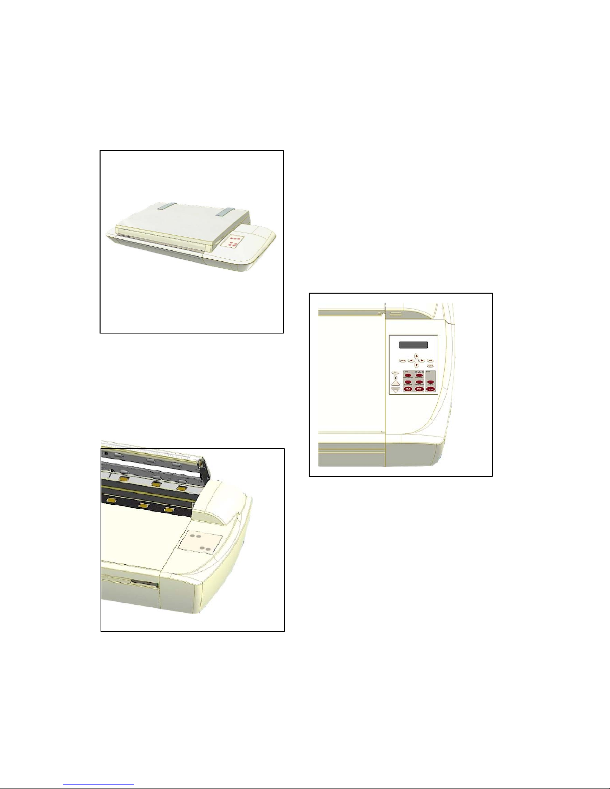
Operator’s Guide
Wide Format
Copy Scanners
with iJET Panel
MODELS:
18” - AA51A
36” - KA67E
February 2006
Page 69

Table of Contents
1. About This Guide 1-1
2. Using the iJET Panel 2-1
2.1 To make a simple copy 2-2
2.2 To perform a simple Scan-to-File 2-2
2.3 Operations on the iJET Panel 2-2
2.4 Power ON/OFF 2-3
2.5 The iJET Panel Buttons - Overview 2-4
2.6 How do I Navigate the iJET Panel Menus? 2-6
3. Scanner Configuration and Setup Instructions 3-1
3.1 Connect the scanner directly to printer(s) - Stand Alone Copier 3-2
3.2 Connect the Scanner to LAN – Network Scan/Copy Device 3-5
3.3 Connect the Scanner to a PC - Scan/Copy workstation 3-9
3.4 Combining Configuration Types for Multiple Functionality 3-12
3.5 Physical Placement of the Scanner 3-13
3.6 Locating the Interface Cable Connector-Panel 3-16
3.7 Personalizing and Localizing Your System 3-18
3.7.1 Setting the iJET Panel’s Display Language 3-18
3.7.2 Setting the Paper Series Preference 3-19
3.7.3 Setting the Media Handling (load) Method Preference 3-20
3.8 Printer Setup on the Scanner 3-21
3.9 Creating Media Profiles – For Color Printer Setup 3-24
3.10 Scanner on Network Setup 3-26
3.11 Setup to Share the Scanner (Use from PCs on the LAN) 3-28
4. Loading Originals for Copying and Scanning 4-1
4.1 How do I Load Originals into the Scanner? 4-1
4.2 Loading and Scanning Thick Media 4-2
5. How do I Make a Copy? 5-1
5.1 Copy Using the iJET Panel – The Basic Steps 5-1
5.2 Main Copy Options - Quick buttons 5-3
5.2.1 How do I… Set Copy Lightness? 5-4
5.2.2 How do I… Set a Scale factor? – Output size 5-5
5.2.3 How do I…Set Copy Quality? 5-6
5.2.4 How do I… Set number of Copies? 5-8
5.3 Other Copy Options – Menu Button 5-9
5.3.1 How do I… Set Original Type Color? 5-9
5.3.2 How do I… Set Original Type B&W? 5-11
5.3.3 How do I… apply the Sharpen filter? 5-12
5.3.4 How do I… apply the Background (Backg.) Clean filter? 5-13
5.3.5 How do I… Set the Media Type? 5-14
5.3.6 How do I… Mirror the Image? 5-16
5.3.7 How do I… Reset Copy defaults? 5-17
5.3.8 The Advanced option 5-18
5.4 Using Copy Software with the scanner (local or network PC) 5-19
6. How do I Scan to File? 6-1
6.1 Scan to Local or Network PC with the iJET Panel 6-2
6.2 Scan-to-File Menu Options – iJET Panel 6-4
6.2.1 Enter the iJET Panel Scan-to-File Menu 6-4
6.2.2 Set the Scan Mode 6-5
6.2.3 Set the Scan Mode Parameters – Level or Gamma 6-6
6.2.4 Set the Scan-to-File Resolution 6-7
6.2.5 Set the Scan-to-File Size (input size) 6-8
6.2.6 Set the File Format ( TIFF, JPEG, PDF ) 6-9
6.2.7 Set the File Format Quality 6-10
6.2.8 Using Scan Software – From Local PC or Network PC 6-11
Page 70

7. Maintenance 7-1
7.1 Preliminary Maintenance – scanner setup 7-1
7.2 Regular Scanner Maintenance 7-1
7.3 Cleaning the Scan Area 7-2
7.4 Running the Scanner Maintenance Program 7-5
7.4.1 Starting Scanner Maintenance from the iJET Panel 7-5
7.4.2 Starting Scanner Maintenance from a PC on the LAN 7-5
7.4.3 Starting Scanner Maintenance from a Local PC 7-5
7.4.4 Running Scanner Maintenance - Steps 7-6
7.5 Replacing Scanner Parts 7-8
7.5.1 Replacing the Glass-plate 7-9
7.5.2 Replacing the White-Background 7-11
7.5.3 Replacing the Scanner Lamp-Unit 7-13
7.5.4 Replacing the Dust-Filters 7-17
7.6 Locate / Change the Smart Card 7-19
7.7 Downloading New Firmware 7-21
8. Appendix A: Important Safety Instructions 8-1
9. Appendix B: Regulations 9-1
FCC Regulations 9-1
10. Appendix C: iJET Panel Quick Reference Guide 10-1
About the Quick Reference Guide 10-2
iJET Panel Buttons Overview 10-3
iJET Panel Menu diagrams 10-5
Option Description Tables 10-19
Page 71
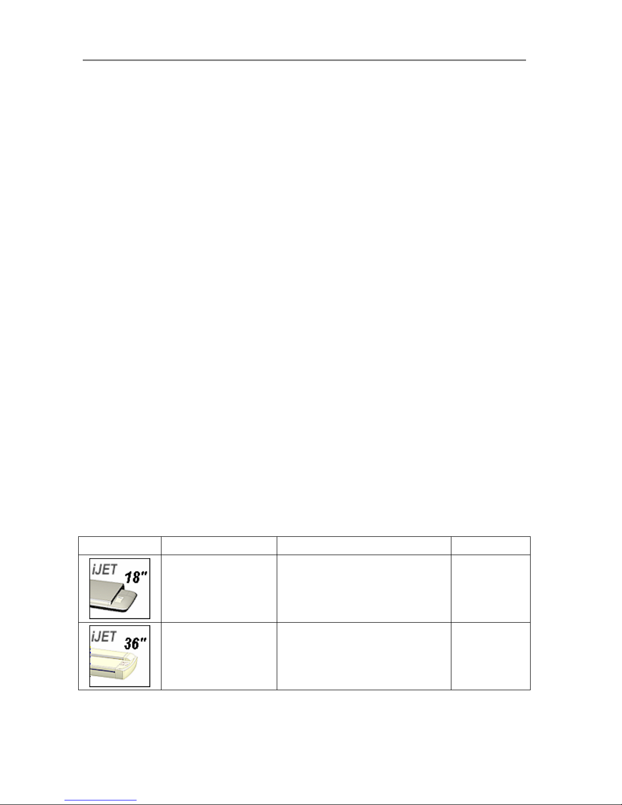
About This Guide 1-1
1. About This Guide
This guide explains how to maintain and operate your wide format copy (iJET) scanner and its
iJET Panel. The guide assumes basic knowledge of other optional configuration components
such as printer, computer and operating system and does not repeat material from their
documentation.
Be sure to refer to:
• The Installation Guide – accessed from the menu on the WIDEsystem TOOLS CD-ROM
– describes installation of your driver if interfacing your scanner with a PC.
• The readme.htm file in the ws folder on the WIDEsystem TOOLS CD-ROM – contains the
most current installation and OS compatibility issues.
• WIDEsystem TOOLS Help – Press F1 after installing and opening WIDEsystem. –
Contains information on using the WIDEsystem application, Scan2Net functionality and
Scanner Maintenance software if interfacing your scanner with a PC.
Scope
This guide covers installation, operation and maintenance of your scanner. The guide covers
only copying and scanning operation through the iJET Panel.
The scanner can also be operated and controlled though compatible scan and copy software
installed on a PC that is either directly connected with the scanner or on the same network.
While this guide will provide instructions on setting up the scanner with a PC, it will not describe
in detail how to operate the scanner from that PC. Operation of scan and copy software is not
within the scope of this guide. Please refer to the software’s documentation and on-line help for
instructions on using the specific software application with the scanner.
Identify your scanner model icon
This operator’s guide covers several scanner models, although there are individual differences
between the models. Use the guide’s scanner type icons to direct you to descriptions about
your specific scanner model. Topics describing scanner functions that apply solely for specific
models will be marked with one or several of the icons shown in the table below. Topics
describing functions that apply for all models will be marked with all the icons.
Before proceeding, identify the icon that applies to your scanner model. You can then use the
icon throughout this guide to find the function description that applies for your specific scanner.
If in doubt as to which icon refers to your scanner model, see the Model ID on the sticker on the
back of the scanner. Models not listed in the table below are not within the scope of this guide.
Icon in Guide Applies for scanners… Main Characteristics
Model IDs
18” (A2) wide format
copy scanners
• Top fed - Flatbed
• iJET Panel
AA51A
36” wide format copy
scanners
• Sheet fed - Insertion slot
• iJET Panel
• ATAC (Automatic Thickness
Adjustment Control)
KA67E
Page 72
About This Guide 1-2
Additional Guide Icons:
• Reference additional Details within this guide – Look for the “Manual” icon
The Manual Icon:
marks a reference to another section in this guide where you can
find more instructions on a certain function just named.
• Operation from the panel – Look for the “On the iJET Panel” icon
The On the iJET Panel Icon:
marks instructions to actions you perform by pressing the
buttons on the scanner’s copy operator’s panel.
• Actual iJET Panel Button – Look for the “Button” icon
The Button Icon will often appear in this guide together with the iJET Panel Icon. The
Button Icon marks which button to look for and press on the iJET Panel to initiate an
action. The icon will contain the button name as seen on the iJET Panel. For example,
instructions describing an action reached through the menu button will be marked with the
button icon:
Menu
Page 73
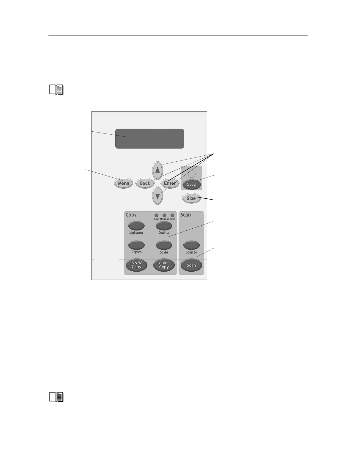
The iJET Panel 2-1
2. Using the iJET Panel
Before setting up your copy/scan configuration, you will need to familiarize yourself with the
iJET Panel. A number of setup tasks are performed through the iJET Panel and will require that
you know how to navigate the iJET Panel’s menus.
Instructions on making specific settings will be described under each configuration type in
the chapter “Copy Scanner Configuration and Setup”.
Scan Option Area
Copy Option Area
Control Buttons
Size Button
Menu Button
Display Window
Stop Button
The iJET Panel enables you to perform advanced copy and scan-to-file jobs straight from the
scanner (and not from a PC and scanning software interface). The panel contains a display
window, control buttons and option buttons.
• The Display Window contains the current selections as you make them and useful
messages from the scanner regarding maintenance and operation.
• The Menu button leads to a options for copy settings and an Advanced submenu for
configuration settings.
• The control buttons arrow up, arrow down, Back, Enter, are for navigating the menus
and for selecting menu options.
• The Stop button is for interrupting a copy or scan process.
• The Size button is for setting the original’s size (input size) for both copy and scan jobs.
• Below the control and menu buttons, are a Copy Option Area and a Scan Option Area,
each with its own set of quick option buttons. These buttons are described below.
A complete overview of the panel’s buttons follows at the end of this section.
Page 74

The iJET Panel 2-2
2.1 To make a simple copy
The following procedure for making a copy presumes the following:
• The scanner and printer(s) are setup correctly as described in this Operator’s guide.
• The Size button option is set to Auto.
• Options such as Lightness, Scale, Original Type, Quality and so on are all set to your
standard settings and the job does not require special adjustments.
1. Load the original
2. Press the Color Copy button for color jobs or B&W copy button for B&W jobs.
or
For jobs that require adjusting the copy parameters, see the section “How do I make a Copy?”
See also relevant sections for setting up the system and setting options.
2.2 To perform a simple Scan-to-File
The following procedure for making a copy presumes the following:
• The scanner is setup correctly with a local or network PC as described in this Operator’s
guide.
• The Size button option is set to Auto.
• Scan-to button options such as Scan Mode, File Format, Resolution and so on are all set to
your standard settings and the job does not require special adjustments.
1. Load the original
2. Press the Scan to button and select a scan target. A (USB) target is a local PC.
3. Press the Scan button to start the job.
For jobs that require adjusting the Scan to parameters, see the section “How do I Scan to File?”
See also relevant sections for setting up the system and setting options.
2.3 Operations on the iJET Panel
• Turn the scanner power ON/OFF (Wake-up and Sleep modes))
• Make quick settings for Copying – Lightness, Quality, Copies (no. of..) and Scale.
• Make additional high level copy settings through the Menu button.
• Apply scanner and printer setup options through the Menu button - Advanced.
• Apply personal and local preferences through the Menu button - Advanced.
• Select a scan-to-file target through the Scan to button.
• Make advanced scan-to-file settings through the Scan to button
• Start a Copy (BW or Color) job.
• Start a Scan-to-file job.
Scan to
Scan
B&W
Copy
Color
Copy
Page 75
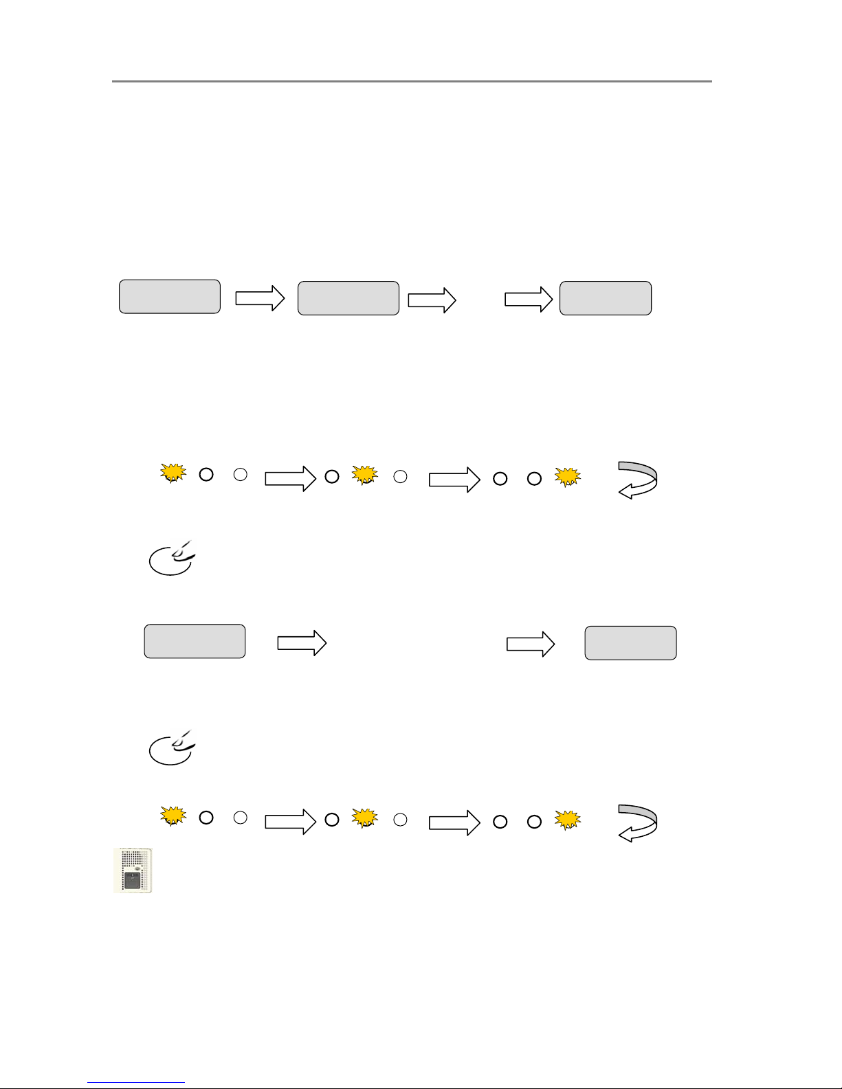
The iJET Panel 2-3
2.4 Power ON/OFF
These power on/off instructions apply only after you have setup and configured your
system as described in the relevant sections under “Scanner Configuration and setup”.
First time during setup (hard power ON)
1. Connect the scanner to the power outlet and turn on the outlet switch (scanner’s back).
2. The scanner runs a self-test and init procedure and after warming up it is ready to scan.
3. The text in the display window will tell you what the scanner is doing and when the
scanner is ready to scan. Prior to the “Ready” message the scanner will need to self adjust.
Normally, after powering up for the first time as described above, you will leave the outlet switch
permanently in the ON position, and turn scanner power on and off in the “soft” manner from
the iJET Panel as described below. This is the method recommended for daily use as it is faster
than hard power on.
To turn power ON from the iJET Panel (wake-up mode)
1. The scanner must be OFF in Sleep mode. When the scanner is in Sleep mode, you will see
the 3 Print Quality LEDS flashing alternately as shown below.
Press and hold down the STOP button for a few seconds until the iJET Panel’s display
window becomes active (lights up).
2. The text in the display window will tell you what the scanner is doing and when the scanner
is ready to scan. Prior to the “ready” message the scanner may need to initialize itself and
warm up.
To turn power OFF (Sleep) from the iJET Panel
1. Press and hold down the Stop button
for a few seconds until the iJET Panel’s display
window light goes off.
When the scanner goes in OFF in Sleep mode, the 3 Print Quality LEDS light alternately as
shown below.
NOTE: The outlet switch at the back of the scanner must be constantly flipped to the ON
position in order to control power with Wake-up and Sleep modes.
NOTE: Power management through Wake-up Sleep modes can be controlled automatically
with WIDEsystem. See the WIDEsystem help for details.
Stop
Initializing
FW:xxxx
…….
Ready
Fast Normal Best
Fast Normal Best
Fast Normal Best
Stop
Fast Normal Best
Fast Normal Best
Fast Normal Best
Initializing
FW:xxxx
Adjusting
Ready
…….
Page 76

The iJET Panel 2-4
2.5 The iJET Panel Buttons - Overview
The Menu button
Menu button - The Menu button leads to the total range of options for copying and also the
Advanced menu with all the system setup and configuration functions.
A complete description on how to navigate the menu and select options follows below.
The Back button
Control Button – for moving one level up when in a menu or for returning to an option’s current
(active) setting while in the process of editing the option’s value.
The Enter button
Control Button – for entering the menu functionality for changing an option’s value and for
setting (accepting) the value once it is selected.
The Size button
Settings button - For setting the size of the original. The Size button is used for both copy and
scan-to-file operation. Press the button to activate option setting. You then change the value
each time you again press the button or with the arrow up/down buttons. You can select Auto
detection or a standard size setting.
NOTE that Size is a global system variable that can be changed in 3 different ways: 1. With the
Size button 2. With the Menu button > Size option and 3. With the Scan-to button > Size option.
This means that when you change the size for a copy job, it will also apply for a scan-to-file job
and vise versa unless you change it again.
The Lightness button
Settings (quick) button - For increasing or decreasing lightness in the copy. Press the button to
activate option setting. You then change the value each time you again press the button or with
the arrow up/down buttons.
The Quality button
Settings (quick) button - For setting copy quality to Fast, Normal or Best. Press the button to
activate option setting. You then change the value each time you again press the button or with
the arrow up/down buttons.
The Copies button
Lightness
Copies
Quality
Menu
Back
Enter
Size
Page 77

The iJET Panel 2-5
(…Copies button) Settings (quick) button - For setting the number of (how many) copies you
want output. Press the button to activate option setting. You then change the value each time
you again press the button or with the arrow up/down buttons.
The Scale button
Option button - For setting a value that defines the output size in relation to the input size. For
making copies larger or smaller than the original. Press the button to activate option setting.
You then change the value to predefined scale ratios each time you again press the button. Use
the arrow up/down buttons for fine tuning - 1 step increments of the currently displayed value.
Press the Enter button to save.
The B&W Copy button
Action Button: The B&W Copy button will start the copy job using the settings made for B&W
copying through the Menu button and the Size, Quality, Copies, Lightness and Scale buttons.
The Color Copy button
Action Button: The Color Copy button will start the copy job using the settings made for Color
copying through the Menu button and the Size, Quality, Copies, Lightness and Scale buttons..
The Scan to button.
Menu Button - For selecting a scan-to-file target (PC on the network) and for setting scan-to-file
options. You change the scan target each time you press the button. Keep pressing until you
see the right target in the window. Then, pressing will lead to the Scan Menu with its
wide range of scan-to-file options you can select for the job. Scan-to-file options include modes,
formats, and resolution.
The Scan button
Action button - The Scan button will start a scan job using the settings made for scanning
through the Scan To button.
The Stop button
Action Button – This button has 2 functions: 1. For interrupting and terminating a scan or copy
job before it is finished. 2. For turning the scanner ON, OFF into Wake-up and Sleep modes.
More details on using the iJET Panel buttons with copy and scan-to-file tasks are
described in the relevant sections in the chapters “How do I Make a Copy” and “How do I Scan
to File?”.
Color
Copy
B&W
Copy
Scan
Stop
Scan to
Scale
Ente
r
Page 78
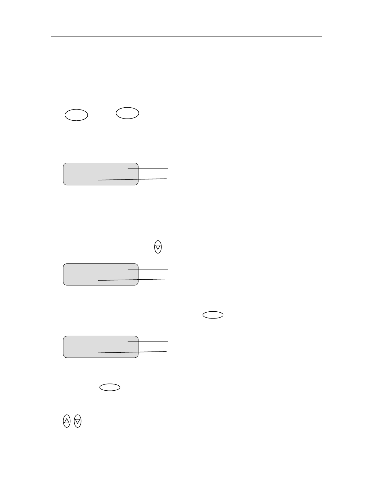
The iJET Panel 2-6
2.6 How do I Navigate the iJET Panel Menus?
This section explains how you find and set the many options behind the Menu button and the
Scan to button. You will learn here how menu options and values are shown in the display
window and how you use the control buttons Back, Enter and arrows up/down to reach them for
setting and changing their values.
2. When you press the one of these buttons you start its underlying menu.
or…
3. A menu contains an ordered list of menu option items and each of these menu option items
can be set to different values. Only one menu option item can be shown at a time in the
display window. When you start a menu, its first menu option item and its current value is
shown in the display window as shown below for the Menu button.
4. The first line in the display is the menu option item and the second line is its current value.
In the example above, the current menu option item is “Org. Type Color” and its value is
“Photo”. The “>” marks which one of the two lines is currently active for changing with the
arrow up/down buttons. In the example above, the first line, i.e the menu option item line is
active.
Pressing the down arrow button in this case will move the menu forward to the next
menu option item and that option’s own current setting as shown below:
5. The “>” marker in the example above shows that the menu option item “Org, Type B&W” is
now active and “Sepia” is its current setting. To enter the menu option in order to make
changes to its setting, you press the Enter button.
In the display panel the “>” mark will move down to the next line as shown below.
6. The “>” marker now indicates that the setting for “Org. Type B&W” option can be changed.
Pressing the up/down arrow buttons will move through the available settings. Press the
Enter button when the right setting is displayed to the right of the “>” marker. The
selected setting will then become the option’s active setting and the “>” marker will hop
back to the menu level (top line) so you can resume leafing through the menu option items
with the arrow up/down buttons.
Org. Type B&W
> Se
p
ia
Menu option item
Current settin
g
for the option item
> Org. Type B&W
Se
p
ia
Menu option item
Current settin
g
for the option item
Menu
Scan to
Ente
r
Ente
r
> Org. Type Color
Photo
Menu option item
Current setting for the option item
Page 79
The iJET Panel 2-7
7. From the display window shown above to the display window below: The user pressed the
arrow down button until the value “Line” was displayed and then pressed to accept
that value as the new setting for the “Org. type B&W” option. The “>” marker moved back to
the menu option item level enabling the user to continue navigating the menu with the arrow
up/down buttons.
8. When in a menu, you can press the Back button
to return to a previous menu
level or to reset the active option item to its last saved value.
9. Press the Stop button if you need to cancel a started scan-to-file or copy job.
10. The copy area quick buttons Lightness, Quality, Copies and Scale are shortcuts to option
items behind the Menu button. Their values can be changed through repeated pressing of
the quick button or else in the traditional manner with the arrow up/down buttons as with
other menu option items.
The quick buttons Lightness, Quality, Copies and Scale are described in detail in the
relevant sections of the chapter “How do I Make a Copy”.
> Org. Type B&W
Line
Menu option item
Current settin
g
for the option item
Stop
Back
Enter
Page 80
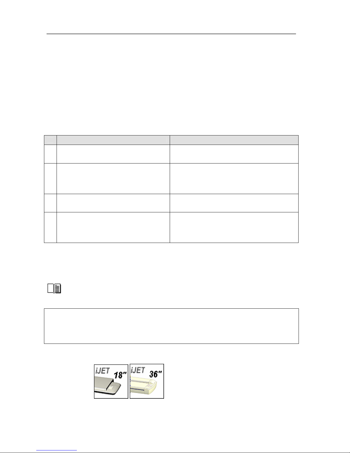
Configuration and Setup 3-1
3. Scanner Configuration and Setup Instructions
Your Copy scanner supports iJET technology for copy and scan-to-file functionality. The iJET
panel enables you to set options on the scanner so you can copy straight from the device
without a controller-PC and software. Furthermore, your scanner can be connected directly to
the LAN enabling it to function with other devices such as printers and PCs that are on the
same network. Finally, your scanner supports both USB device (input) and USB host (output)
interfaces for direct connection to a printer and to a PC that can control the scanner through
scan/copy software.
This wide range of connection and operation capabilities means that your scanner can be set
up in many different ways or “configurations” to match the needs of your business. For clarity,
we have termed the main configuration possibilities and their components as follows:
Configuration Type Components - Description
1 Stand Alone Copier Configuration Scanner connected directly (no PC) to one or two printers.
2 Network Scan/Copy Device
Scanner connected directly (no PC) to the network. The
scanner is set up to be recognized on the network by
network PCs and also setup to recognize/use network PCs
as scan targets. The scanner is setup to use network
printers.
3 Scan/Copy Station on Local PC
Scanner connected to a PC through USB interface.
Scan/copy software is installed on the PC.
4 Combinations of the above for Multiple Functionality
The scanner is connected to a local PC and a local printer.
The scanner is also connected directly to the network in
order to be shared by network PCs and to use network
PCs as scan targets. The scanner can also use network
printers.
This operator’s guide section describes each of these configurations, including its components,
requirements and step-by-step installation instructions. Please note that combinations of the
first three configurations (present in above list as configuration nr. 4) are not only possible, but
in many cases also recommended in order to get the full range of scan-to-file and copy
functions out of your device and maximum flexibility for your business .
More on combining configurations in the section “Combining Configuration Types for
Multiple Functionality.”
NOTE: About interface connection cables: Your scanner came with a number of interface
cables. Refer to the supplied document: “NOTE ON INTEFACE CABLES” for instructions on
which cables to use with your specific configuration.
All the configurations described in the following sections apply…
On All Scanners
Page 81
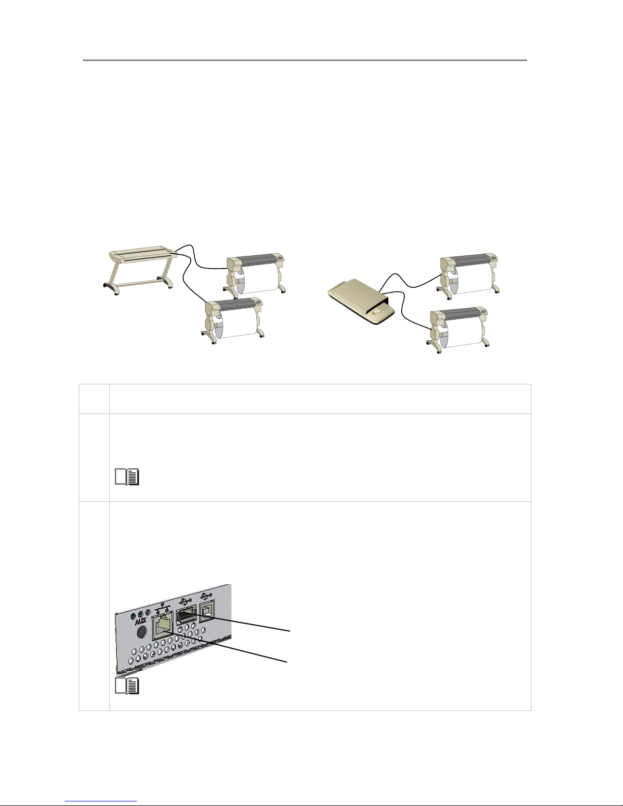
Configuration and Setup 3-2
3.1 Connect the scanner directly to printer(s) - Stand Alone Copier
Components: Wide format copy scanner and one or two large format printers. The Scanner is
connected directly (no PC or network) to one or two printers.
Usage: For copying large format documents. This configuration can create printed output only.
All operation takes place from the iJET Panel (scanner).
System Requirements:
• Wide Format Copy scanner
• Compatible large format printer(s)
• USB cable or twisted LAN cable or both. - for connecting the scanner to the printer(s)
Printers are connected through USB or LAN interface
Step Description – Stand Alone Copier Configuration
1 Set up your scan station and control the smart card
Your wide format copy scanner should be placed either on the specially designed stand-alone floor stand or on
a sturdy table. For sheet-feed models, make sure there is enough space behind the scanner to allow the media
to run out.
Make sure that the scanner’s smart card is in place.
See the sections “Physical Placement of the Scan Station” and “Maintenance-Locate the Smart Card” for
detailed instructions for your specific scanner model.
2 Connection – scanner end
Connect the USB cable or LAN cable to the scanner. Check your printer’s interface options to select which of
these to use. For USB use the USB host (output) port which is the flat rectangle shaped socket. See the
document: “NOTE ON INTERFACE CABLES” for instructions on the specific interface cable types to use with
this configuration.
You can attach two printers at a time – a B&W printer and a Color printer. Note that the scanner has only one
USB out connection so a second printer will have to be able to use the LAN connection.
LANport
USB host port
(output to printer)
See the section “Locating the Interface Cable Connector Panel” for instructions regarding your specific
scanner model.
Page 82
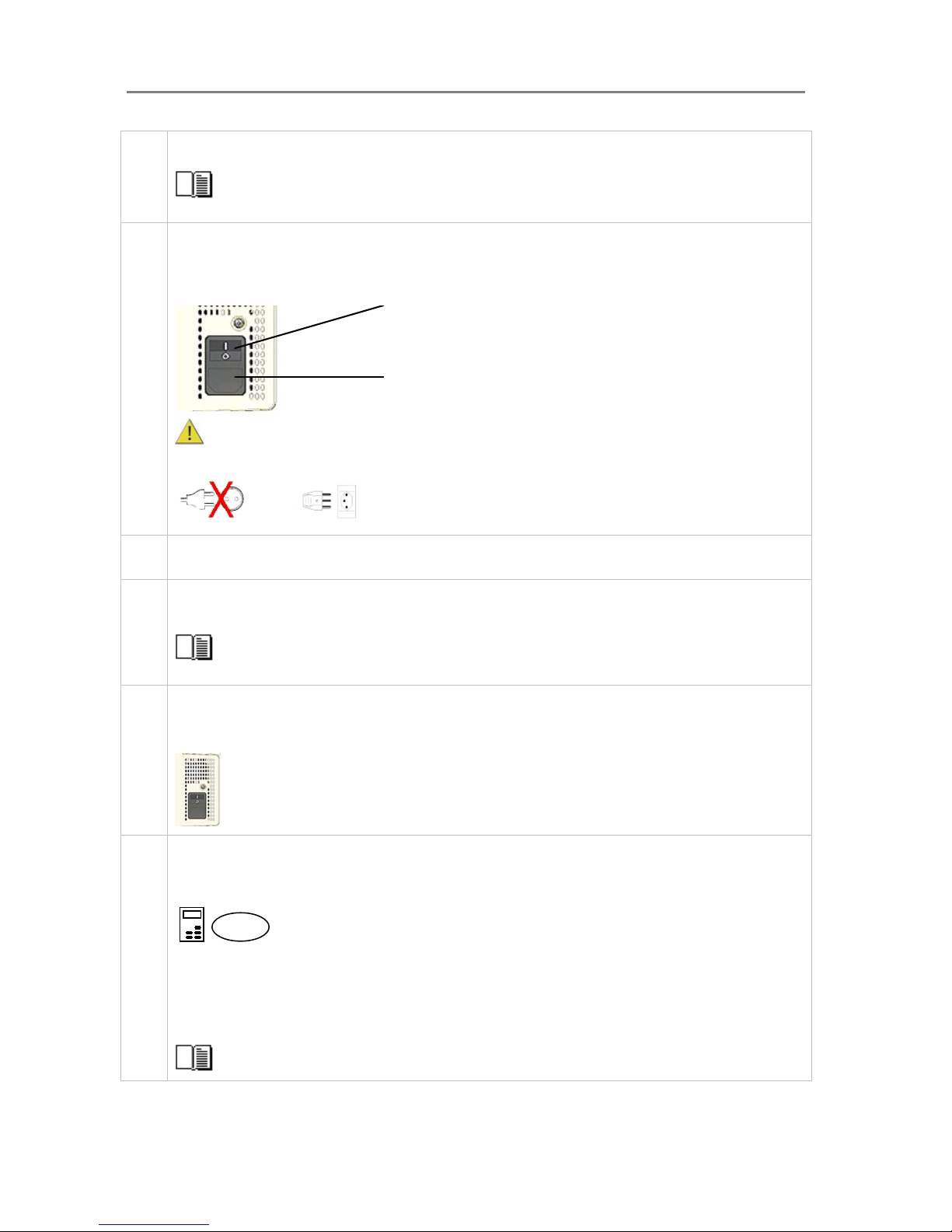
Configuration and Setup 3-3
3 Connection - printer end
Connect the other end of the USB interface cable or LAN cable to the large format printer.
See the section “Locating the Interface Cable Connector Panel” for detailed instructions for your specific
scanner model.
4 Connect scanner power cable
At back of the scanner, you will find the scanner-end power cable socket, just below an Outlet switch. Connect
the cable to the scanner plug socket and the grounded power source. Do not yet turn on the Outlet switch on
the scanner.
Scanner-end power socket
Caution: The scanner is equipped with a three-wire (pin) grounding type plug. If you cannot insert the
plug into your outlet, contact your electrician to replace the outlet and ensure a grounded power connection. Do
not try to defeat or ignore the purpose of the grounding-type plug.
5 Connect the printer’s power cable.
6 Perform Preliminary Maintenance – Cleaning
Clean your scanner’s flat surface so dirt and dust are not dragged into the scan area with the original. Clean the
internal Scan area.
See the section “Scanner Maintenance” for instructions on accessing the scan area and cleaning for your
specific scanner model.
7 Turn (power) on the scanner and the printer
To turn on the scanner - at back of the scanner, above the scanner-end power cable plug you will find an Outlet
switch. Flip the Outlet Switch to ON. The scanner starts the init and self test sequence and you must wait until
these are finished.
Power outlet and switch is found at the back of the scanner
Perform Preliminary Maintenance - Calibration
Some scanner models support calibration from the iJET panel. For other models you will need to use a PC with
WIDEsystemNET and Scanner Maintenance software installed
.
To run scanner maintenance:
On the iJET Panel
Select Menu > Advanced > Options > Calibrate Scanner > Yes to start calibration. If the option is not present in
the iJET panel menu:
Use a local or LAN connected PC with WIDEsystem and Scanner Maintenance installed. Left click on the
WIDEsystem scanner Icon and select Launch Scanner Maintenance from the menu. Follow the instructions on
your screen.
See the section “Scanner Maintenance” for detailed instructions.
Menu
Page 83
Configuration and Setup 3-4
8 Set localization Preferences
On the iJET Panel - Select Menu > Advanced > Options >… to set preferences for language, paper series and
media handling (loading).
See the section on options for ”Personalizing and localizing the system” for details.
9 Make Printer Setup settings on the scanner
You can setup for two printer types – a B&W printer and a color printer. After you setup your printers, pressing
the Color Copy button will send the output to your color printer and pressing the B&W Copy button will send the
output to your B&W printer.
On the iJET Panel
Printer set up is described for Color Printer below. The same rules and method applies for B&W Printer setup.
Select Menu > Advanced > Printer Setup > Color Printer to make settings.
Select Menu > Advanced > Printer Setup > Color Printer > Interface > USB if you used a USB connection
between the scanner and the printer and LAN if you used a LAN connection. If you selected LAN, use the arrow
up/down buttons to enter the printer’s IP address.
Select the Printer Model setup method – Auto Configure, Printer List or Custom Setup and apply the additional
setting(s) attached to the Printer Model setup method you selected.
See the section on “Printer Setup on the Scanner” for more details.
10 Turn On and Prepare the Printer
Perform actions and settings on the printer device such as check that the right paper is loaded and the printer is
ON. See your printer’s documentation for help.
11 Create a system media type for your printers media (Closed Loop Calibration)
For the color printer only - You must create a system media type profile in order to color match paper media,
printer and scanner before using the system. Identify the media type (Coated, Glossy, Semi-Glossy) you use
with the printer then perform closed loop calibration (3 steps).
On the iJET Panel
Select Menu > Advanced > Options > Closed Loop Cal.
Press Enter and then use the arrows up/down buttons to reach the right media type and Enter to select.
On “Print Sheet” select Enter. The system will print a color patch sheet.
Feed the sheet into the scanner
On “Scan Sheet” select Enter. The system will scan the color patch sheet and calculate color matching values
for future jobs with the current media type.
See the section on “how do I… Create a New Media Type” for more details.
12 Test your system
Make a simple copy to test your system.
See the section on “how do I… Make a Copy” for details.
Menu
Menu
…..
Page 84
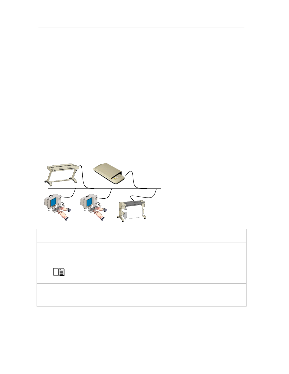
Configuration and Setup 3-5
3.2 Connect the Scanner to LAN – Network Scan/Copy Device
Components: Wide format copy scanner and Local network. Peripheral devices such as PCs
and printers are setup and active on the network. The scanner will be setup to recognize PCs
on the network as scan-to-file targets. The scanner will also be setup to be recognized and
accessed by PCs on the network (sharing). The scanner will be setup to recognize and use
network printers.
Usage: For copying and digitizing large format documents. For creating both printed and file
(digitized) output. Operation is from the iJET Panel (scanner) or from network PCs. Users
operating from the panel can copy to printers on the network and scan-to-file to PCs on the
network. Network PCs with compatible scan or copy software installed can “share” the scanner
and use it with network printers or for scan-to-file tasks.
System Requirements:
• Wide Format Copy scanner
• Compatible large format printer on the network (for copy functionality).
• LAN cable connecting the scanner to the network.
• One or more PCs on the network (for scan to file and shared scanner functionality).
• The PCs need: compatible operating system (see ws/readme.htm on WIDEsystem TOOLS
CD).
Scanner’s LAN interface
Step Description
1 Set up your scan station and control the smart card
Your wide format copy scanner should be placed either on the specially designed stand-alone floor stand or on
a sturdy table. For sheet feed models, make sure there is enough space behind the scanner to allow the media
to run out.
Make sure that the scanner’s smart card is in place.
See the sections “Physical Placement of the Scan Station” and “Maintenance-Locate the Smart Card” for
detailed instructions for your specific scanner model.
2 Connection – scanner end
Connect the LAN cable to the scanner’s LAN port. See the document: “NOTE ON INTERFACE CABLES” for
instructions on the specific interface cable type to use with this configuration.
Page 85
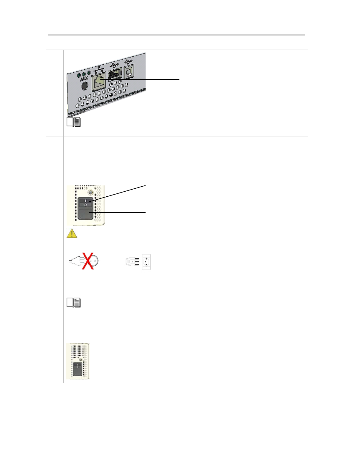
Configuration and Setup 3-6
LAN port
See the section “Locating the Interface Cable Connector Panel” for instructions regarding your specific
scanner model.
3 Connection – network end.
Connect the other end of the LAN cable to the network or switch.
4 Connect scanner power cable
At back of the scanner, you will find the scanner-end power cable socket, just below an Outlet switch. Connect
the cable to the scanner plug socket and the grounded power source. Do not yet turn on the Outlet switch on
the scanner.
Scanner-end power socket
Caution: The scanner is equipped with a three-wire (pin) grounding type plug. If you cannot insert the
plug into your outlet, contact your electrician to replace the outlet and ensure a grounded power connection. Do
not try to defeat or ignore the purpose of the grounding-type plug.
5 Perform Preliminary Maintenance – Cleaning
Clean your scanner’s flat surface so dirt and dust are not dragged into the scan area with the original. Clean the
internal Scan area.
See the section “Scanner Maintenance” for instructions on accessing the scan area and cleaning for
your scanner model.
6 Turn (power) on the scanner and the printer
To turn on the scanner - at back of the scanner, above the scanner-end power cable plug you will find an Outlet
switch. Flip the Outlet Switch to ON. The scanner starts the init and self test sequence and you must wait until
these are finished.
Power outlet and switch is found at the back of the scanner
Page 86
Configuration and Setup 3-7
Perform Preliminary Maintenance – Calibration
Some scanner models support calibration from the iJET panel. For other models you will have to use a PC with
WIDEsystem and Scanner Maintenance software installed
. To run scanner maintenance:
On the iJET Panel
Select Menu > Advanced > Options > Calibrate Scanner > Yes to start calibration. If the option is not present in
the iJET panel menu:
Use a local or LAN connected PC with WIDEsystem and Scanner Maintenance installed. Left click on the
WIDEsystem scanner Icon and select Launch Scanner Maintenance from the menu. Follow the instructions on
your screen.
See the section “Scanner Maintenance” for detailed instructions.
7
Set localization Preferences
On the iJET Panel - Select Menu > Advanced > Options >… to set preferences for language, paper series and
media handling (loading).
See the section on options for ”Personalizing and localizing the system” for details.
8 Make Printer Setup settings on the scanner
You can setup for two printer types – a B&W printer and a color printer. After you setup your printers, pressing
the Color Copy button will send the output to your color printer and pressing the B&W Copy button will send the
output to your B&W printer. In this configuration, both printers are on the network.
On the iJET Panel
Printer set up is described for Color Printer below. The same rules and method applies for B&W printer setup.
Get the network id information for the printer(s) you want to use from your network administrator.
Select Menu > Advanced > Printer Setup > Color Printer to make settings.
Select Menu > Advanced > Printer Setup > Color Printer > Interface > LAN. Use the arrow up/down buttons to
enter the printer’s IP address.
Select the Printer Model setup method – Auto Configure, Printer List or Custom Setup and apply the additional
setting(s) attached to the Printer Model setup method you selected.
See the section on “Printer Setup on the Scanner” for more details.
9 Make Scanner Network Setup settings on the scanner
On the iJET Panel
Select the Menu > Advanced > Network Setup. You can use DHCP network setup if your network supports it.
Otherwise you need to enter the network address information manually. Contact your network administrator for
the correct address values. Select Menu > Advanced > Network Setup > Share Scanner > Yes if you want to
enable PCs on the network to use the scanner.
See the section on “Scanner on Network Setup Settings” for details.
10 Turn On and Prepare the Printer
Perform actions and settings on the printer device such as check that the right paper is loaded and the printer is
ON. See your printer’s documentation for help.
11 Create a system media type for your printers media (Closed Loop Calibration)
You must create a system media type profile in order to color match paper media, printer and scanner before
using the system. Identify the media type (Coated, Glossy, Semi-Glossy) you use with the printer then perform
closed loop calibration (3 steps).
Menu
Menu
Menu
Menu
Page 87
Configuration and Setup 3-8
On the iJET Panel
Select Menu > Advanced > Options > Closed Loop Cal.
Press Enter and then use the arrows up/down buttons to reach the right media type and Enter to select.
On “Print Sheet” select Enter. The system will print a color patch sheet.
Feed the sheet into the scanner
On “Scan Sheet” select Enter. The system will scan the color patch sheet and calculate color matching values
for future jobs with the current media type.
See the section on “how do I… Create a New Media Type” for more details.
12 Test your system
Make a simple copy to test your system.
See the section on “how do I… Make a Copy” for details.
13
Verify Scan to File functionality
Scan to a network PC to test Scan to file functionality. The PC must have WIDEsystemNET installed and must
be setup for network scanning.
See instructions on setting up a PC for scan2net in WIDEsystemNET on-line help. See more on
scanning to a PC in the section “How do I…
Control from the iJET Panel – Scan to local or network PC”
14
Verify Shared Scanner functionality
The netwok PC must have WIDEsystemNET and compatible scan/copy software installed. Check that you can
identify the scanner from the PC and perform a test scan.
See instructions on setting up a PC for scan2net in WIDEsystemNET on-line help. See more on using a
shared scanner in the scan or copy application’s on-line help.
Menu
Page 88
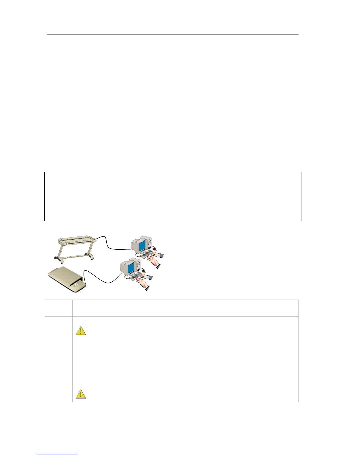
Configuration and Setup 3-9
3.3 Connect the Scanner to a PC - Scan/Copy workstation
Components: Wide format copy scanner and PC. For scanning to file and saving on local PC.
If this configuration is to be used for copying purposes, it must include a printer that is either
connected directly to the PC (local printer) or the PC can be connected to the network and have
access to network printers.
Usage: For digitizing large format documents. Used for scan-to-file (digitized) output only
unless a printer is attached to the PC or PC to network printers. Operation is possible both from
the iJET Panel and from the PC.
System Requirements:
• Wide Format Copy scanner
• PC with Compatible operating system (see ws/readme.htm on WIDEsystem TOOLS CD)
• USB port on the PC
• The WIDEsystem TOOLS CD supplied with your scanner.
• Scanning software or compatible third party software.
NOTE: Scanning and Copying in this configuration would often be performed through scan
and copy software installed on the PC rather than through the scanner’s iJET Panel.
Usage of scan and copy software is not within the scope of this operator’s guide. Please refer to
the software’s documentation and on-line help for instructions on using the software with the
scanner.
Users can scan-to-file to the PC from the iJET Panel in this configuration. See the section “How
do I Scan to File?” in this guide.
Scanner’s USB device (input) interface
Step Description
1 Insert the WIDEsystem TOOLS CD-ROM into your PC.
IMPORTANT : DO NOT YET CONNECT THE SCANNER TO POWER OR PC. install WIDEsystem
before you connect the scanner or install any scanner software applications. Your scanner drivers are
automatically installed with WIDEsystem and your PC will then be fully prepared to detect and setup the
newly connected scanner device.
Start up the WIDEsystem TOOLS CD-ROM by inserting the CD-ROM into your PC. Normally the setup
program interface will start automatically. If it does not, perform the following steps to activate it.
Click the Start button on the Taskbar and choose Run from the menu.
Type D:\setup in the Command Line Box (where D: represents the name of your CD-ROM
drive).
Choose the OK button.
Important: Be sure to use the WIDEsystem TOOLS CD-ROM that came with your scanner or a
Page 89
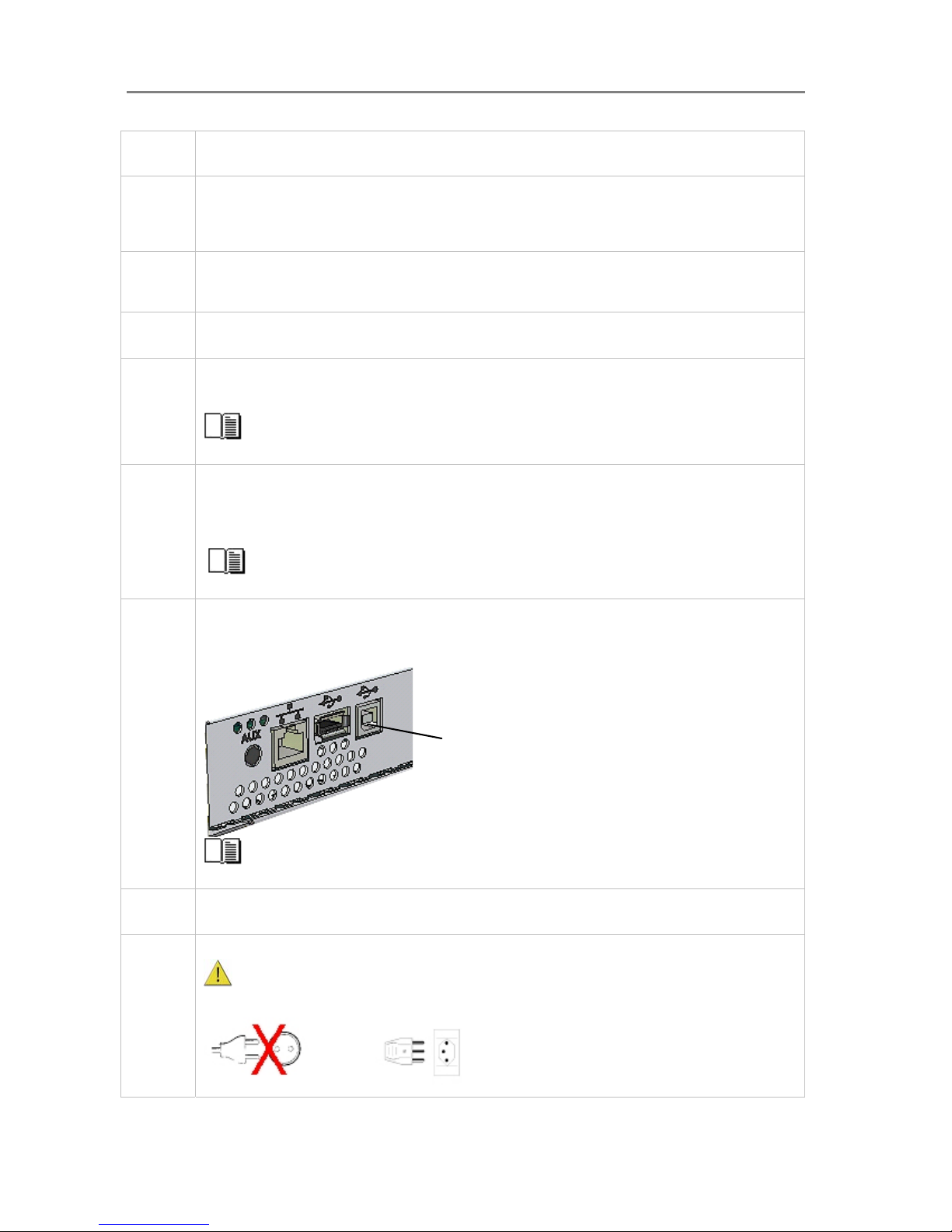
Configuration and Setup 3-10
newer version. Out-of-date versions of WIDEsystem software may not detect your scanner model.
2 Install WIDEsystem Software
Click on the option Install WIDEsystem Software from CD main menu or run the setup.exe program
directly from the WIDEsystem (ws) folder on the CD-ROM. Follow the installation instructions that appear
on your screen.
3 Install Scanner Maintenance Software
Click on the option Install Scanner Maintenance Software from CD’s menu. Follow the instructions that
appear on your screen.
4 Shut down (power off) the PC
Your PC is now prepared and must be powered off before connection with the scanner.
5 Perform Preliminary Maintenance – Cleaning
Clean your scanner’s flat surface so dirt and dust are not dragged into the scan area with the original.
Clean the internal Scan area.
See the section “Scanner Maintenance” for instructions on accessing the scan area and cleaning
for your specific scanner model.
6 Set up your scan station and control the smart card
Your wide format copy scanner should be placed either on the specially designed stand-alone floor stand
or on a sturdy table. For sheet feed models, make sure there is enough space behind the scanner to
allow the media to run out.
Make sure that the scanner’s smart card is in place.
See the sections “Physical Placement of the Scan Station” and “Maintenance-Locate the Smart
Card” for detailed instructions for your specific scanner model.
7 Connect the interface cable – scanner end
Connect the USB interface cable to the scanner’s USB device (input) port (squared formed socket). See
the document: “NOTE ON INTERFACE CABLES” for instructions on the specific interface cable type to
use with this configuration.
USB device (input) port
See the section “Locating the Interface Cable Connector Panel” for instructions relating to your
specific scanner model.
Connect the interface cable – PC end
Connect the other end of the USB cable to the PC’s USB connection port (flat rectangle socket).
8 Connect scanner power cable
The scanner is equipped with a three-wire (pin) grounding type plug. If you cannot insert the plug
into your outlet, contact your electrician to replace the outlet and ensure a grounded power connection.
Do not try to defeat or ignore the purpose of the grounding-type plug.
Page 90
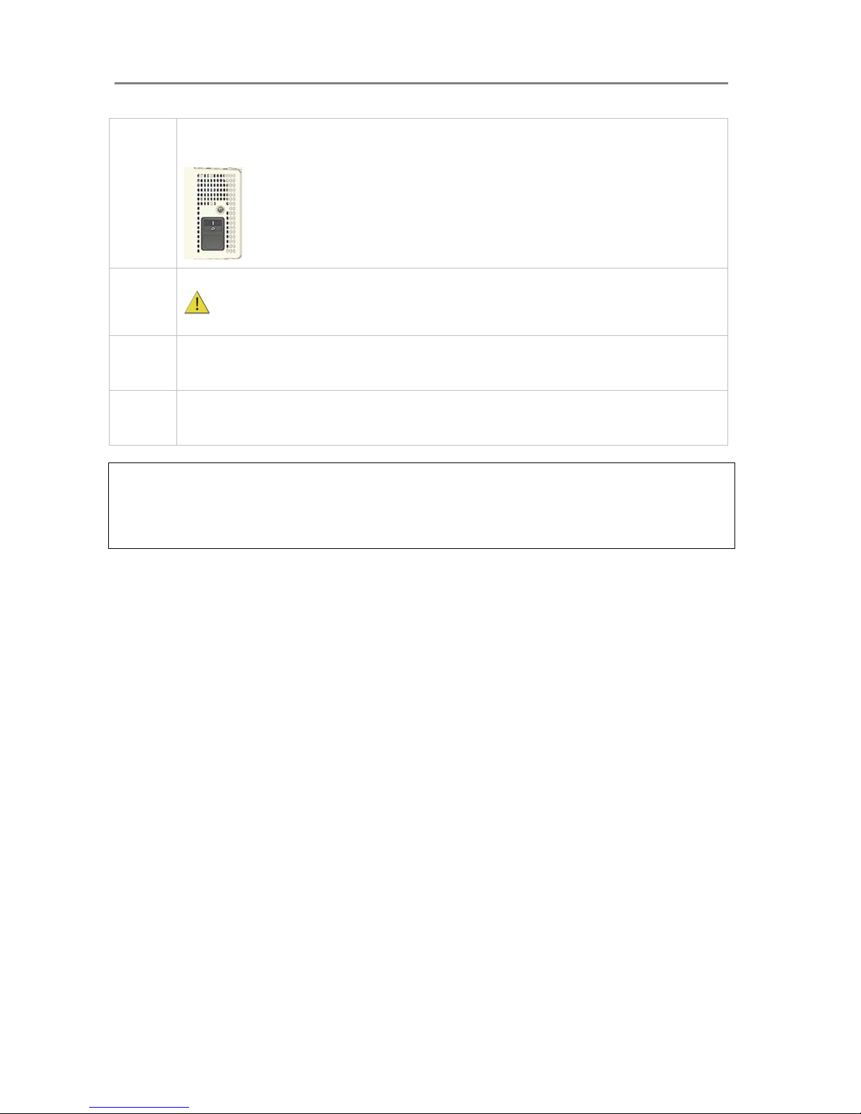
Configuration and Setup 3-11
9 Turn on the Scanner
To turn on the scanner - at back of the scanner, plug in the power cable and flip the Outlet Switch to ON.
The scanner starts the init and self test sequence.
Power outlet and switch is found at the back of the scanner
10 Turn on the PC
Make sure the PC connected to the scanner is likewise power-connected to a grounding-type power
outlet with a three-wire (pin) grounding type plug.
11 Verify installation of new hardware
Double click on the WIDEsystem scanner icon on the Windows system tray. The program should detect a
Selected Scanner in the dialog.
12 Run preliminary Scanner Maintenance - Maintenance program
Left click on the WIDEsystem scanner Icon and select Launch Scanner Maintenance from the menu.
Follow the instructions on your screen.
NOTE: On Windows Compatibility - Your scanner and drivers are tested and developed to
support the most current active Microsoft Windows version OS systems. Drivers and interface
support in regard to specific Windows versions will follow the Microsoft Support Lifecycle Policy.
The compatibility specifications can therefore change accordingly. The most current OS
compatibility specifications and drivers will be available on your manufacturer’s website.
Page 91
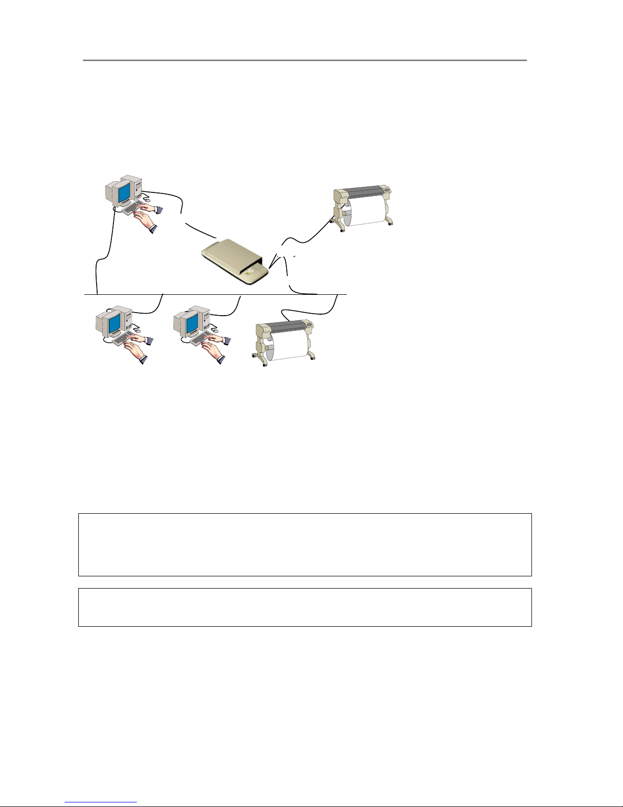
Configuration and Setup 3-12
3.4 Combining Configuration Types for Multiple Functionality
Although they were described separately, the three configurations: Stand alone copier, Scan/
Copy device on a network, Scan/ Copy station on local PC can be combined to provide multiple
functionality. For most companies, a combined solution would be recommended to get the
most out of the scanner and provide a flexible, multi-purpose device.
Scanner’s USB device (input) interface
Scanner’s USB host (output) interface
Scanner’s LAN interface
In the example illustrated above, we have connected both a printer and a PC directly to the
scanner and both the scanner and the PC are each attached directly to the network. This
means that the configuration can be used as a stand alone copier, a stand alone scan-to-file
station, a device for saving scans to network PCs and a shared device that can be controlled
and used by network PCs. The scanner can use both the local printer and printers on the
network. Both scan-to-file and copying can be performed either through the iJET Panel or
through scan/copy software.
Use the instructions for each configuration in the previous sections for setting up a combined
solution. You will find that many of the steps are general and apply for all configurations so you
only need to perform them once.
NOTE: Your Copy Scanner supports a single LAN connection port. This means that if you
connect a printer directly through this port, you will not be able to set up a combined solution
with network accessibility. You can use LAN switch boxes to work around this problem. It is
advisable to use the USB host (output) port for direct printer connection if USB connectivity is
supported on the printer.
Regulatory Notice: Your scanner product has been tested to comply with the EMC Standards
EN55022 and FCC, Part 15. To maintain compliance, only use the interface cables supplied
with the scanner.
Page 92

Configuration and Setup 3-13
3.5 Physical Placement of the Scanner
Please follow the guidelines below for optimal safety, scanner functionality, and scanning
results.
Physical placement of the scan station:
On Scanners:
Your wide format flatbed scanner should be placed on a stabile, level and completely flat
(plane) surface such as a sturdy table. If convenient, you can place the backend of the scanner
against a wall. The lid will not open all the way back and stops at an approximate 65
0
angle.
It is very important to follow the instructions below to ensure the scanner is setup with optimal
stability and without tension on the scanner’s frame. Failure to do so can produce poor
scanning results and cause damage to the scanner device over time.
The scanner rests on feet placed at the bottom of the scanner. Some flatbed scanner models
support 4 adjustable feet while later flatbed models have 3 fixed feet and 2 adjustable feet (total
of 5 feet). See the instructions below for each type of feet-configuration.
4 feet models
1. These scanners are more sensitive to uneven surfaces and it is best to ensure that you
have a completely plane surface.
2. Position (tighten) all four feet all the way up so they all have an equal height.
3. Place the scanner on the flat surface aligned in its optimal position for usage.
4. You can make slight adjustments to the feet if necessary. Use a long object to get in
under the scanner and rotate the feet to lengthen them. Only very slight adjustments
are acceptable. If major adjustments are required, you should find another table with a
flatter surface.
5 feet models
1. The two outer feet closest to the operator’s panel side are adjustable. The middle foot
on the same side and the two feet on the other side are fixed. See the illustration
below.
2. The 2 adjustable feet should be positioned (tightened) all the way up when setting up
the scanner on its new surface. They are delivered in that position from the
manufacturer.
3. The 2 adjustable feet (in their original position as described in step 2) are slightly
shorter than the 3 fixed feet. Therefore the scanner will at first rest only on the 3 fixed
feet (1 on the operator panel side and 2 on the opposite side).
4. Use a screwdriver or an alternative long slim object to access and rotate the 2
adjustable feet until they touch the surface so all 5 feet are in contact with it.
5. If the scanner is moved, the 2 adjustable feet must be retightened to their original
(shortest) position and the steps above must be repeated.
Page 93
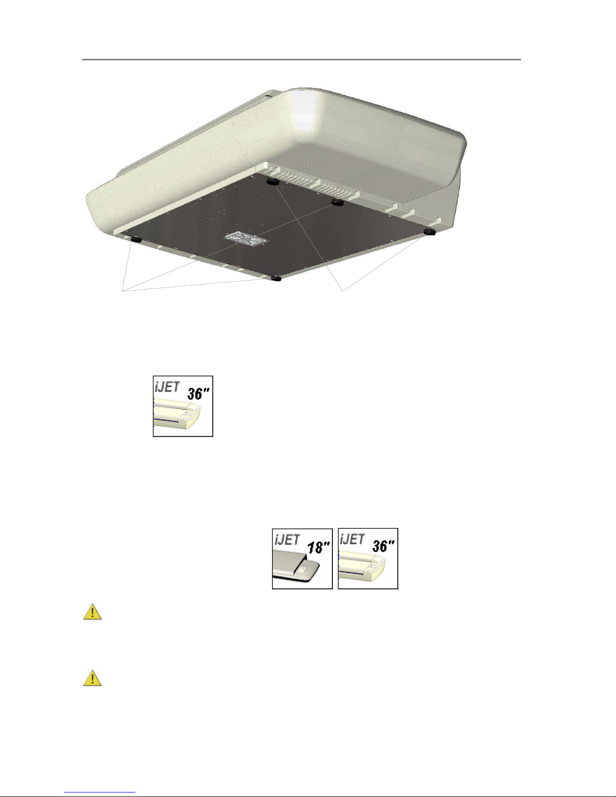
Configuration and Setup 3-14
2 adjustable feet
Original position must be all the way up (shortest feet)
3 fixed feet
Physical placement of the scan station:
On Scanners:
Your wide format scanner should be placed either on the specially designed stand-alone floor
stand or on a sturdy table. Make sure there is enough space behind the scanner to allow the
media to run out. Thick stiff media naturally requires space that is at least as large as the media
length.
Physical placement of the scan station:
Guidelines that apply for all scanners:
Slots and openings in the cabinet at the back and bottom are provided for ventilation. This
ensures reliable operation of the product and protects it from overheating. These openings must
never be blocked or covered by placing the unit on a bed, sofa, rug, or other similar soft
surface.
Your scanner should never be placed near or over a radiator or heat register.
Page 94
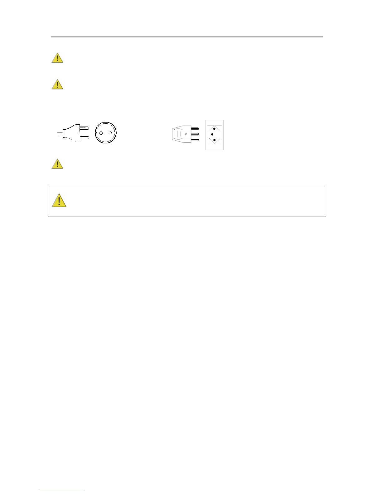
Configuration and Setup 3-15
You should not place the scanner in a built-in installation unless proper ventilation is
provided.
The scanner is equipped with a three-wire (pin) grounding type plug. This plug will fit only
into a grounding-type power outlet. This is a safety feature. If you cannot insert the plug into
your outlet, contact your electrician to replace the outlet and ensure a grounded power
connection. Do not try to defeat or ignore the purpose of the grounding-type plug.
X
Make sure the PC connected to the scanner is likewise power-connected to a groundingtype power outlet with a three-wire (pin) grounding type plug.
See also the Safety Instructions at the end of this operator’s guide.
Page 95
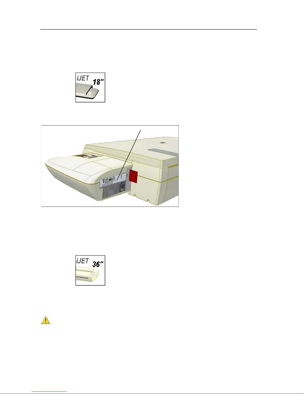
Configuration and Setup 3-16
3.6 Locating the Interface Cable Connector-Panel
Your scanner’s interface cable connectors are grouped in a cable connector panel. You will
need to locate the cable connector panel in order to insert interface cables when setting up the
system. You can find your scanner’s cable-connector-panel as follows:
On Scanners:
The scanner has LAN, USB device (input) and USB host (output) interface connectors grouped
in a cable-connector-panel. The cable-connector-panel is found at the back of the scanner.
The cable-connector-panel is found on the scanner’s back.
Locate the cable-connector-panel
On Scanners:
The scanner has LAN, USB device (input) and USB host (output) interface connectors grouped
in a cable-connector-panel. You will find the cable-connector-panel by removing the scanner’s
right side cover. You feed the interface cable through the opening in the back of the scanner
until it emerges in front of the cable-connector-panel.
Be sure to reattach the cover after you connect the interface. The cover must always be
closed before you turn the scanner ON.
Page 96
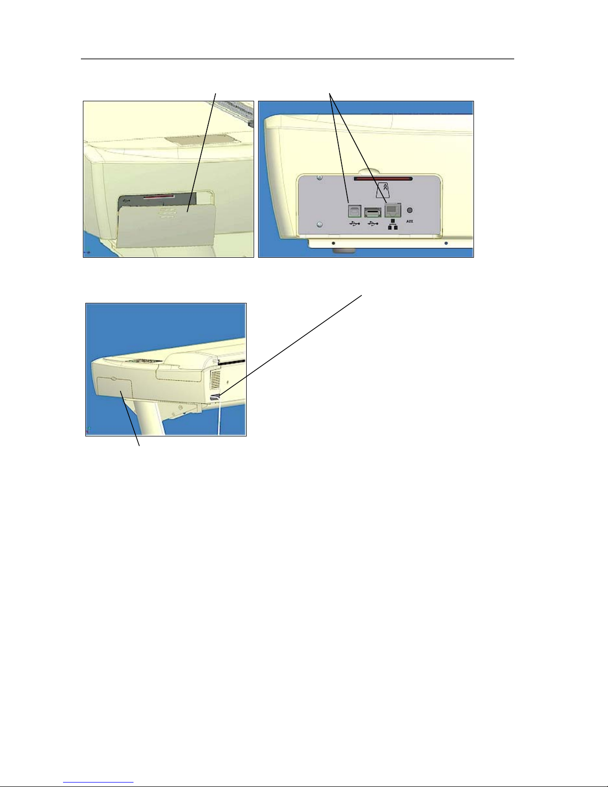
Configuration and Setup 3-17
Remove the scanner’s right side cover
Interface connectors (cable-connector-panel)
Feed the interface cable through the hole in the back until it emerges in interface are a.
Interface area is behind the cover
Page 97
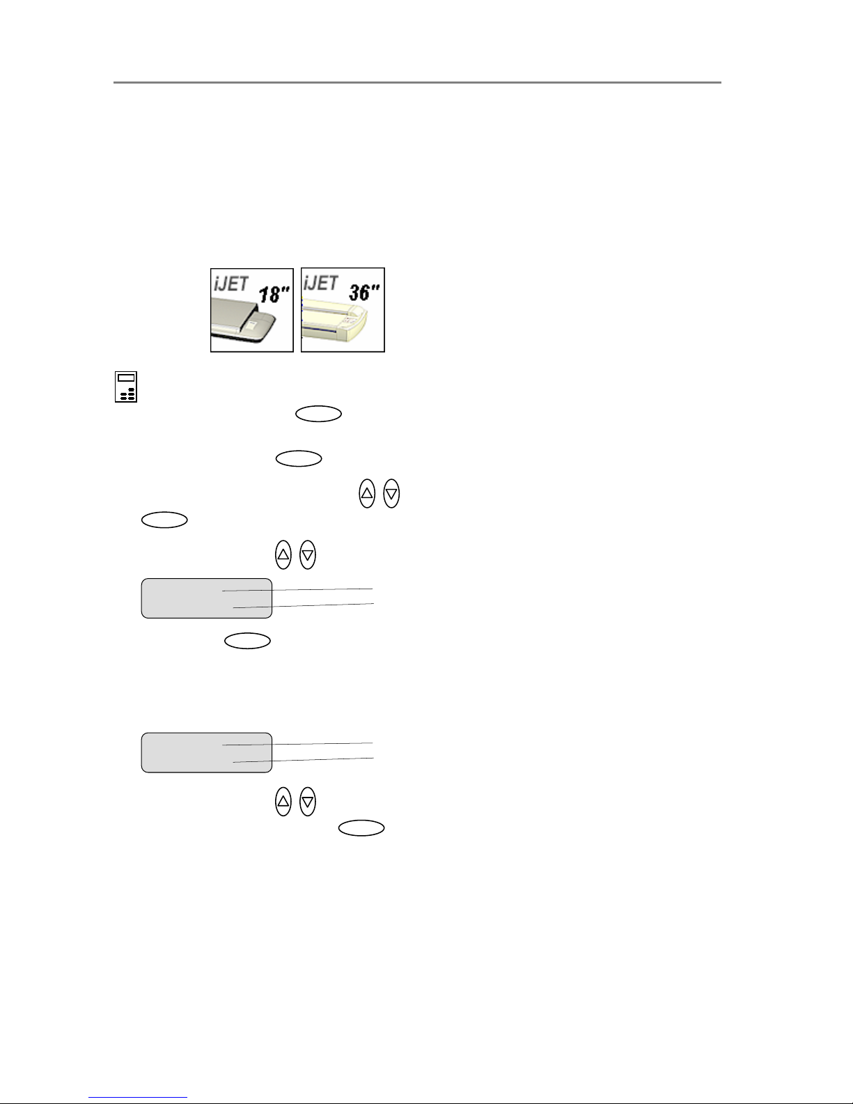
Configuration and Setup 3-18
3.7 Personalizing and Localizing Your System
The iJET Panel options can be configured to match your local standards regarding the
language displayed in the menus, paper size series (preferred standard size systems such as
“ARCH” and ISO A) and media handling (original’s loading method).
NOTE: The number of languages available for the panel is limited.
3.7.1 Setting the iJET Panel’s Display Language
On scanners:
On the iJET Panel
1. Select the Menu button.
2. Use the arrow button up or down until the display windows shows Advanced and confirm
with the Enter button .
3. Use the arrow buttons up or down until the display shows Options and confirm with
.
4. Use arrows down/up until the display shows Language. .
5. Confirm with . The “>” marker will move down to the option setting line so you can
change it.
6. Your display should look like this (the actual text to the right of the “>” will show the current
setting for the option and may be different than the one shown below).
7. Use arrows down/up to select the language you want to use for the texts in the iJET
panel’s disply and confirm with .
Ente
r
Menu option item
Current setting for option item
> Language
English
Menu option item
Current setting for option item
Language
> En
g
lish
Ente
r
Enter
Menu
Enter
Page 98
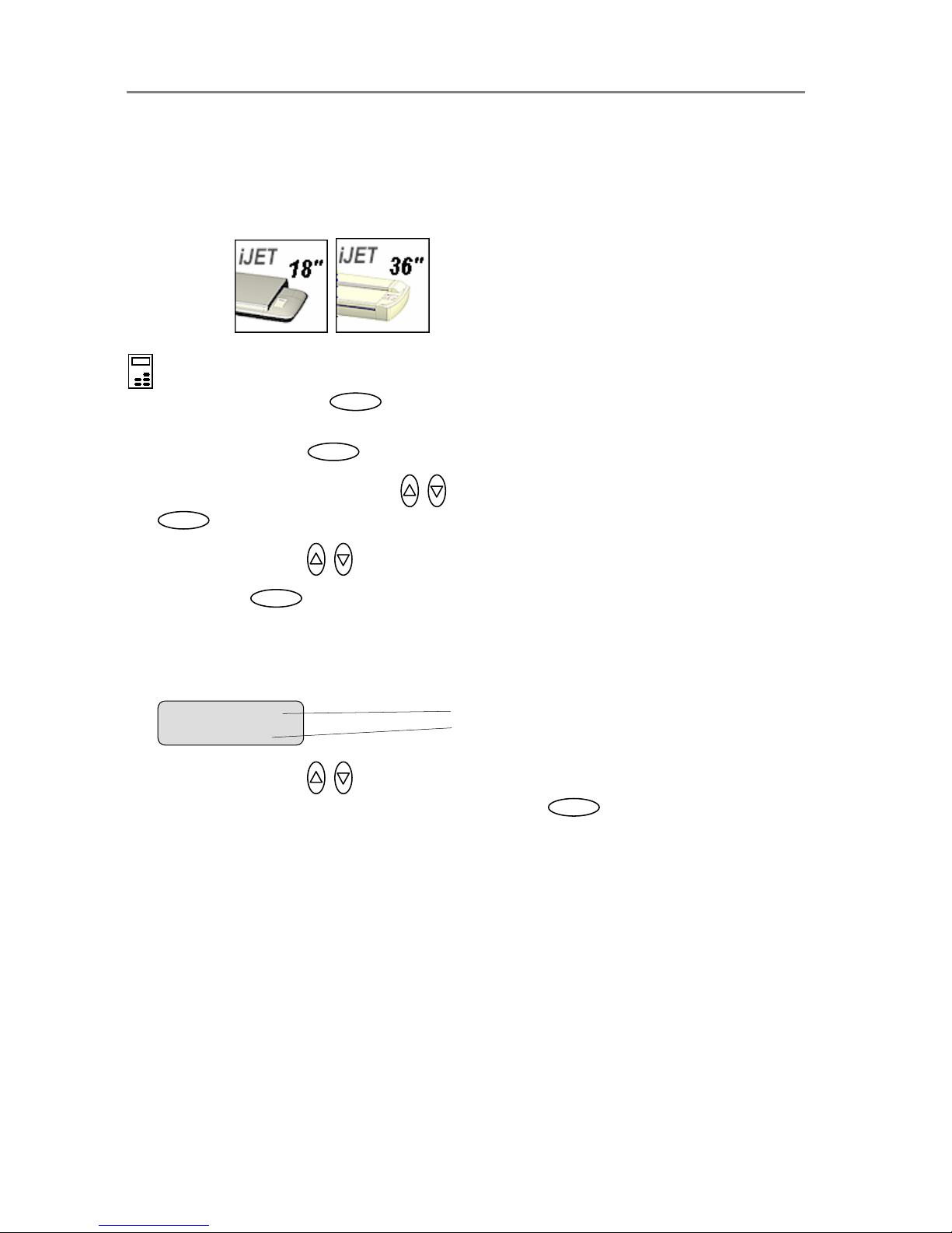
Configuration and Setup 3-19
3.7.2 Setting the Paper Series Preference
Depending on your location and business, you may usually work with a specific standard paper
series. This option lets you tell the system which paper series you want displayed when you set
the Size (input size) option. You can also tell the system to always display all the paper series’
in the system.
On scanners:
On the iJET Panel
1. Select the Menu button.
2. Use the arrow button up or down until the display windows shows Advanced and confirm
with the Enter button .
3. Use the arrow buttons up or down until the display shows Options and confirm with
.
4. Use arrows down/up until the display shows Paper Series.
5. Confirm with . The “>” marker will move down to the option setting line so you can
change it.
6. Your display should look like this (the actual text to the right of the “>” will show the current
setting for the option and may be different than the one shown below).
7. Use arrows down/up to select the paper series (...ARCH, ANSI, ISO A...) you want to
use when setting the paper size and confirm with Enter . You can also select ALL if
you need to use more than one paper series.
Ente
r
Menu option item
Current setting for option item
Paper Series
> ALL
Ente
r
Enter
Menu
Enter
Page 99

Configuration and Setup 3-20
3.7.3 Setting the Media Handling (load) Method Preference
This option lets you tell the system how you want to load originals into the scanner.
On scanners:
(not relevant on flatbed models)
On the iJET Panel
1. Select the Menu button.
2. Use the arrow button up or down until the display windows shows Advanced and confirm
with the Enter button .
3. Use the arrow buttons up or down until the display shows Options and confirm with
.
4. Use arrows down/up until the display shows Media Handling and confirm with
.
5. Your display should look like this (the actual text to the right of the “>” will show the current
setting for the option and may be different than the one shown below).
6. Use arrows down/up to select the method you want to use and confirm with .
Auto Load means the scanner will pull the original into the scan area as soon as you insert
it into the slot. You can set a Load Delay factor with Auto Load (see next step). Manual
Load means you insert the original and press on the panel’s feed forward button.
7. If you selected Auto Load and want to change the delay factor – Make sure the Media
Handling option is marked with the “>”. If not press enter to move it up. Use arrow down
to reach the Load Delay option. Confirm with Enter . Use the arrows to set a
Load Delay factor and confirm with . These steps are illustrated below.
Press
Enter
to confirm
A
uto Load
Media Handling
> Auto Load
The the ‘>’ mark will have moved
up to the menu option line - Media
Handlin
g
.
> Media Handling
Auto Load
Menu option item
Current setting for option item
Media Handling
>Auto Load
Ente
r
Ente
r
Enter
Enter
Enter
Menu
Enter
Page 100
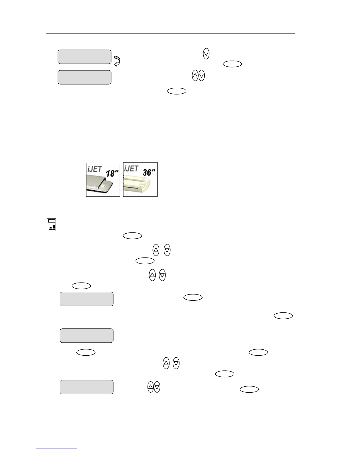
Configuration and Setup 3-21
3.8 Printer Setup on the Scanner
In order to be operated from the iJET Panel, your copy scanner needs to recognize a printer.
The setup procedure depends on whether you connect a printer through the USB host (output)
port or through a LAN port (either directly or indirectly). Direct connection through the LAN port
will require that you enter the local printer’s IP address. If you connect to the network through
the LAN port and want to use a printer on that network, you will have to enter the network
printer’s IP address.
On scanners:
To apply printer setup settings:
On the iJET Panel
1. Select the Menu button.
2. Use the arrow button up or down until the display window shows Advanced and
confirm with the Enter button .
3. Use the arrow buttons up or down until the display shows Printer Setup and confirm
with .
4. You can set up a Color Printer and a B&W Printer (max 2 printers at a time). Press
to reach the Color Printer option.
5. Press to confirm Color Printer and reach the Interface option and again to
confirm Interface. Use arrows down/up to select USB or LAN, depending how you
connected your color printer and confirm your selection with .
Interface
> USB
Use arrows to change the Interface setting. Press
Enter
to confirm.
> Color Printer
…
Press
Enter
to confirm
Printer setup
> Printer Setup
…
Enter
Load Delay
> 3
Use arrows to change the
Load Delay value and confirm with
Enter
.
> Load Delay
0
Use arrow down to reach the
Load Dela
y
option. Press
Enter
Enter Enter
Ente
r
Enter
Menu
Ente
r
 Loading...