

Page 1
Page 2

Internet info:http://www.contex.com
Contex document no.: FSS/USM/004 (2.1)
Copyright Contex A/S, Denmark, January 26, 2001
No part of this publication may be reproduced, stored in a retrieval
system, or transmitted, in any form or by any means, electronic,
mechanical, photocopying, recording or otherwise, without the prior
written permission of the publisher. Contex A/S reserves the right to
modify the information given in this publication without prior notice.
Page 3

I
Preface
The Contex Full Scale Monochrome Scanners provide a complete
solution for scanning drawings, documents and pictures for use with
CAD, DTP, COPY and Drawing Archival applications.
The built-in dedicated high-speed Digital Signal Processor (DSP)
performs image processing and enhancement in real time.
The fast industry standard SCSI I/F and WIDEimage software makes
the Full Scale Scanner truly multi-platform.
The WIDEimage scanning software is available in Windows-98,
Windows SE, Windows ME, Windows 2000 and Windows NT4.0
editions for PCs.
This guide explains how to operate and maintain the Full Scale
Scanner. It assumes a basic knowledge of your computer and
operating system and does not repeat material from their
documentation.
SYSTEM REQUIREMENTS
• WIDEimage scanning software
• PC that fulfils WIDEimage’s minimum requirements
• SCSI interface kit matching your workstation.
RELATED PUBLICATIONS
The "OPERATIONS GUIDE" which came with your computer.
The "OPERATING SYSTEM USER MANUAL" for your workstation.
The "WIDEimage USER's GUIDE".
The "README.TXT" file on the distribution diskettes. Use your text
editor to look for latest news and updates.
Page 4

II
How To Use This Guide
This guide contains six chapters, and six appendices. Make sure you
read the chapter on: "Installation" , before attempting to install or use
the Full Scale Scanner and software described in this guide.
Chapter 1. Is an introduction to the Full Scale Scanner and gives an
overview of its use with different professional applications.
Chapter 2. Gives an overview of the Full Scale Scanner system and
features.
Chapter 3. Describes the functions and the use of the Full Scale
Scanner operator panel and indicators.
Chapter 4. Discusses the Full Scale Scanner’s operating modes.
Chapter 5. Describes installation of the Full Scale Scanner onto your
system.
Chapter 6. Describes how to perform user maintenance on the Full
Scale Scanner.
Appendix A. Lists the Full Scale Scanner Specifications.
Appendix B.. Contains a glossary.
Appendix C. Contains the regulations applicable for the Full Scale
Scanner.
Appendix D. Full Scale Scanner License Agreement.
Appendix E. Important safety information.
Appendix F. Index.
Page 5

III
Table of Contents
1.
Introduction 1-1
1.1 Computer Aided Design 1-2
1.2 Copying 1-3
1.3 Desk Top Publishing Systems 1-3
1.4 Drawing Archival and Management 1-4
1.5 Satellite Photo Scanning 1-4
2. System Overview 2-1
2.1 Software 2-3
3. Operator Panel and Indicators 3-1
4. Operating Modes 4-1
4.1 Line Mode 4-1
4.2 Graytone Mode 4-3
4.3 Photo Mode 4-3
5. Installation 5-1
5.1 Installation of the SCSI board in the PC. 5-2
5.2 Installation Verification 5-2
5.3 Scanner DIL-switch Setup 5-3
5.4 SCSI Termination on FSS Scanners 5-5
6. Maintenance 6-1
6.1 Cleaning the Original’s Scanning Area 6-1
6.2 Adjusting the height of the CCD Cameras 6-2
6.3 Camera Out of Light Error 6-5
7. Appendix A: Specifications 7-1
8. Appendix B: Regulations 8-1
8.1 FCC Regulations 8-1
8.2 EU Regulations 8-2
9. Appendix C: Program License Agreement 9-1
10. Appendix D: Important Safety Instructions 10-1
11. Appendix E: Index 11-1
Page 6

Introduction 1-1
1. Introduction
The Contex Full Scale Scanner x300 models: FSS18300
DSP
,
FSS12300
DSP
, FSS8300
DSP
, FSS8300PLUS
DSP
and FSS4300
DSP
are
monochrome scanners and their drawing width size and resolution
ranges vary as follows:
• FSS18300
DSP
: E-Size(A0) scanning width and up to 1800 dpi
resolution.
• FSS12300
DSP
: E-Size(A0) scanning width and up to 1200 dpi
resolution.
• FSS8300
DSP
: E-Size(A0) scanning width and up to 800 dpi
resolution.
• FSS8300PLUS
DSP
: E-Size(A0) scanning width and up to 800 dpi
resolution. Very high scanning speed. The resolutions can be set
in 1 dpi increments. Includes Area Diffusion Logic (ADL).
• FSS4300
DSP
: E-Size(A0) scanning width and up to 400 dpi
resolution.
The Full Scale Scanner line is produced by Contex, the leading
manufacturer of large format scanners, with many thousands of
installations world-wide.
The Full Scale Scanners are designed to work with all types of
technical scanning applications.
Page 7
1-2 Introduction
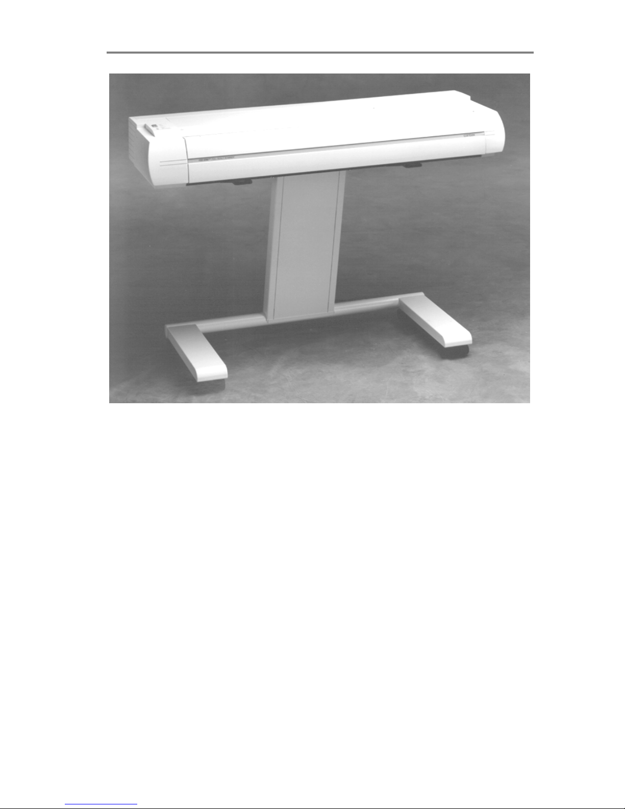
Figure 1-1 Full Scale Scanner
1.1 Computer Aided Design
The Full Scale Scanners (FSS) offer CAD-Systems users easy access
to architectural, civil and mechanical drawings, bridging the gap
between CAD and hard-copy drawing media.
The FSS with its WIDEimage program scans hard-copy originals
directly into the workstation. Formats up to E-Size(A0) can be
scanned, allowing you to capture drawings for modification, storage, or
transmission, or to bring hard-copy drawings on-line.
The FSS scans original line art, maps, blueprints, sepias, vellum and
mylar drawings in high resolution. The Full Scale Scanners have a
built-in white, spring-loaded background pressure platen to support
scanning of transparent originals.
The unique two-dimensional 2D-Adaptive Thresholding and built-in
high-speed Digital Signal Processor provides clean crisp scans from
poor quality drawings on-line, without the need for pre-scan. It
Page 8

Introduction 1-3
automatically adapts to the drawing, compensating for varying
background, faded areas and stains.
CAD-systems such as AutoCAD, VersaCAD, etc., can make full use of
the Full Scale Scanners, either directly or together with raster-editors,
archiving, overlay or raster-to-vector conversion programs. The FSS is
a time saving way to capture the machine-drawn or hand-drawn
originals onto an electronic medium.
1.2 Copying
Using the FSS and WIDEimage with a laser printer provides an
inexpensive and convenient way to transform any large format
technical drawing into standard-sized copy for enclosure in reports or
documentation; or you can output them to an inkjet or laser plotter for
a full size copy.
1.3 Desk Top Publishing Systems
With the FSS you can now scan originals of almost any size into the
computer so their images can be included in technical documents,
user manuals, sales brochures, spare parts catalogues, proposals,
bids, etc., using popular desk top publishing applications such as
Aldus PageMaker or Ventura Desk Top Publisher.
Through WIDEimage the FSS is compatible with most software and
standard DTP file formats. The FSS Window Scan feature allows you
to cut and crop areas of interest out of larger drawings.
With its ease of use and flexibility regarding original sizes and file
formats, the FSS is the scanner of choice for the technical publishing
office.
Page 9

1-4 Introduction
1.4 Drawing Archival and Management
Many of an organization's resources are held in its archives. Electronic
Drawing Management Systems allow on-line access and control of
vital company assets such as scanned mechanical drawings, electrical
schematics and facility plans on hard- or optical disks.
A single CD-ROM can store 800 to 1000 E-Size drawings, meaning
that your archives could contain several hundreds of thousands of
drawings.
Electronically accessing, viewing, modifying, converting and printing or
plotting your drawings saves you time and money.
The FSS supports the Computer Acquisition and Logistics (CALS) and
ISO-ODA standard CCITT Group4 (MIL 28002) drawing archival
formats.
1.5 Satellite Photo Scanning
Use the Full Scale Scanners’ graytone scanning capability of 256
levels, together with applications like CADOverlay GS, to directly
overlay satellite photos in AutoCAD, with image correction facilities.
Page 10

System Overview 2-1
2. System Overview
The Full Scale Scanner uses single, dual, triple, or quadruple 8000
pixel CCD Cameras with individual adaptive light compensation on
each pixel. The FSS includes the following features:
• FSS18300
DSP
: Up to 1800 dpi scan resolution at all original sizes;
64.800 dots at 1800 dpi, scanned at the max. scan width 36" (914
mm), by graytone interpolation and re-sampling of the physical
32.000 pixels (four cameras).
• FSS12300
DSP
: Up to 1200 dpi scan resolution at all original sizes;
43.200 dots at 1200 dpi, scanned at the max. scan width 36" (914
mm), by graytone interpolation and re-sampling of the physical
24.000 pixels (three cameras).
• FSS8300
DSP
: Up to 800 dpi scan resolution at all original sizes;
28.800 dots at 800 dpi, scanned at the max. scan width 36" (914
mm), by graytone interpolation and re-sampling of the physical
16.000 pixels (two cameras).
• FSS8300PLUS
DSP
: Up to 800 dpi resolution, setable in 1 dpi
increments, at all original sizes; 28.800 dots at 800 dpi, scanned
at the max. scan width 36" (914 mm), by graytone interpolation
and re-sampling of the physical 16.000 pixels (two cameras).
• FSS4300
DSP
: Up to 400 dpi resolution at all original sizes; 14.400
dots at 400 dpi, scanned at the max. scan width 36" (914 mm), by
graytone interpolation and re-sampling of the physical 8.000
pixels (one camera).
• Connection to the computer via standard SCSI Interface
• Scanning area sized from A5 up to A0 and E-Size (from 152 mm
up to 914 mm wide). Media size: 152 to 1016 mm.
• Image processing and enhancement options include: 2D-
Adaptive thresholding, histogram analysis, and on-line threshold
variation.
• On-line de-skewing and de-speckling, during simultaneous
scanning of the drawing, producing perfectly horizontally aligned
and speckle-free scans.
Page 11
2-2 System Overview
Scanning Application
Scanning /Image Enhancement.
Prescanning and Previewing.
Selectable Scan Modes.
Standard and custom sizes.
Scaling.
Conversion to over 50 File Formats.
De-speckling.
Rotation & Alignment.
Precision Measuring.
Viewing and Zooming.
Fast Printing.
LARGE FORMAT
PRINTER
Contex Copy and Scanning System
Copy Application
Straightforward User Interface.
Enhancement modes for B/W Sepia,
Photo, and Normal drawings.
Standard Printer – Media Presets.
On-Screen WYSIWYG Previewing.
Tonal adjustment.
Collate Copy.
Additional in JETimage Pro :
Paneling, Tiling Nesting.
Scan to File, Print from File.
Copy Job Accounting.
FSS x300 MONOCHROME
SCANNER
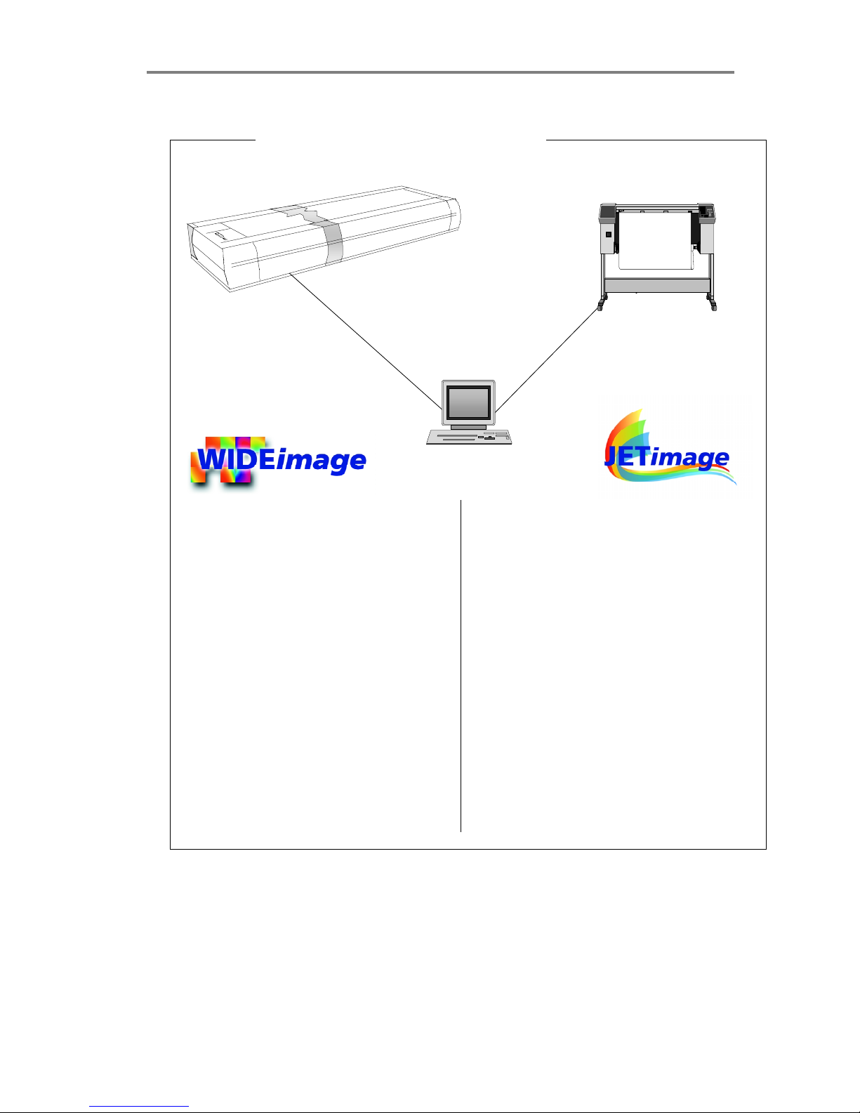
Figure 2-1 Full Scale Scanner System Overview
Page 12

System Overview 2-3
• 256 graytone levels ( 1 Byte, 8 bit per pixel ).
• WIDEimage interface software: Scanning, Conversion, Rotation,
Cropping, Alignment, View, Zoom and Print/Plot of large format
drawings to/between/from multiple industry standard file formats.
SCSI Interface. The supplied interface kit contains a SCSI-PC
extension board that interfaces between the PC bus connector and the
Full Scale Scanner.
2.1 Software
The WIDEimage scanning program produces a multitude of industry
standard graytone and B/W output image file formats compatible with
CAD, GIS, Raster-Editor, Raster-to-Vector, Digitize, Overlay, and
Archiving programs. The application gives users complete control of
the scanner’s advanced functions from the workstation.
WIDEimage is a complete scanning tool that enables scanning,
enhancing, converting, viewing, zooming and printing of wide format
documents.
The JETimage copy program enables you to make large format copies
in quality enhanced graytones and black and white. Your output goes
to a printer via the PC. Available in two editions: JETimage BASE and
JETimage PRO.
JETimage is available in touch-screen and traditional mouse/keyboard
configuration versions. Easy and fast copying can be achieved with a
scanner, a printer with JETimage incorporating all copy functions in
simple and logical buttons.
Easy-to-use interface with predefined settings for the most common
copy jobs, printing media and printers.
Page 13

2-4 System Overview
With JETimage you can perform high quality copying in five easy
steps. Select the type of original you are copying – Photo, Brochure,
etc, and the application finds the best scanning and printing settings
for you. The application make large format reproduction as easy as
using your office copy machine.
JETimage takes full advantage of the CRYSTAL’s graytone
reproduction in printed output using built-in ADL+ Error diffusion
halftoning.
WIDEcapture for Photoshop
Wide Format Scanning Software for Macintosh and Windows as a
Plug-in for Adobe Photoshop. WIDEcapture is a compact application
designed to interface your scanner with advanced graphics software
on an Apple Macintosh or Windows-based platform. The application is
developed for usage with Adobe Photoshop – a leading image
software application among graphics professionals. The software is
designed as a plug-in, meaning it is a full software program that
extends the functionality of the Adobe Photoshop program by enabling
access to Wide Format Scanning. You install the program into Adobe
Photoshop’s plug-in folder and just select the application through
Photoshop’s File menu. WIDEcapture imports images from the
scanner into the Photoshop image editor. You can then use
Photoshop’s wide range of image manipulation options, just as if you
had opened an image file from your hard disk.
WIDEcapture for AutoCAD
Wide Format Scanning Software for direct scanning into AutoCAD
2000 on Windows platforms. WIDEcapture for AutoCAD is a compact
application designed to interface your Wide Format Scanner with the
advanced CAD software AutoCAD 2000. When you install this plug-in
software, a new menu item called "Scanned Raster Image" is entered
in the Insert Menu on your AutoCAD interface. Selecting this item
activates a Wide Format Scanning interface that contains all the
features known from the WIDEimage Scan Screen, including the split
preview screen and special tool buttons.
Page 14

Operator Panel and Indicators 3-1
3. Operator Panel and Indicators
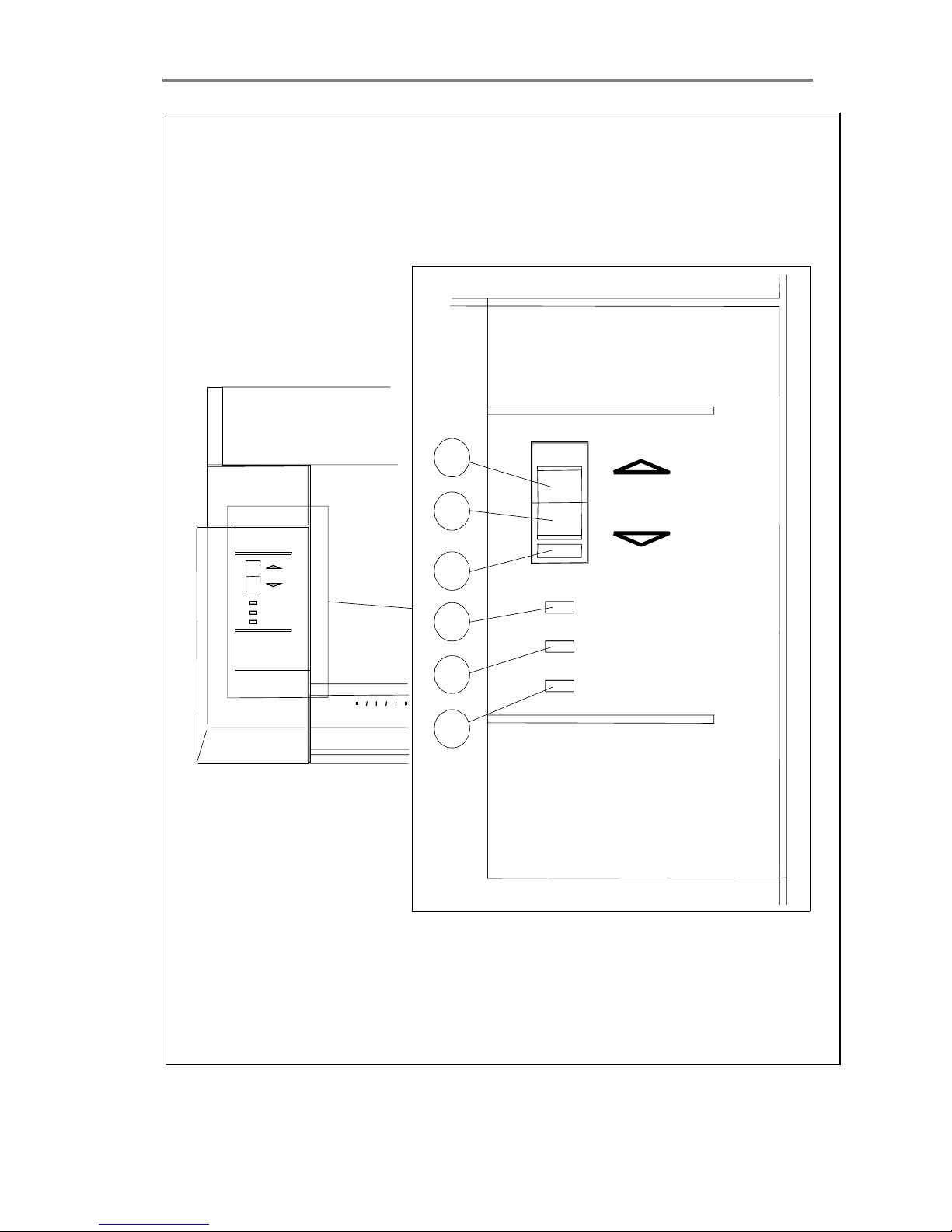
The Full Scale Scanner’s Operator Panel layout shown overleaf is
divided into two keys and four indicators. The two operating keys are
positioned at the top: The Paper Reverse key (C), and the Paper
Feed/Forward key (A) with a Ready Indicator (B) attached. Three
indicators at the bottom: Power on (D), Wait (E), and Diagnostic (F).
The detailed function of the keys and indicators are as follows:
A, B : Paper Feed/Forward Key and Ready indicator.
Insert the drawing face down into the scanner’s insertion slot. The
green Ready Indicator (B) turns on (lights) when the drawing is
correctly positioned. Now press the Feed Forward key (A), and the
drawing will move into the start-of-scan position. The Ready
Indicator stays on (lighted), signifying that the scanner is ready to
be controlled from the computer.
During scanning the Ready Indicator blinks.
At end of scanning the Ready Indicator is again tuned on (lighted
without blinking) signifying that scanning can be repeated from the
computer, or else terminated by the operator if the Paper
Feed/Forward key is pressed to eject the drawing from the
scanner.
Pressing the Paper Feed/Forward key during scanning, stops the
current scanning process and feeds the original as long as the key
is held down.
NOTE : If the drawing is removed from the scanner manually
without pressing the Paper Feed/Forward key to eject, the Ready
Indicator will stay on. This condition can be reset by pressing the
Paper Feed/Forward key.
C : Paper Reverse Key.
The reverse key stops the current scanning process and reverses
the original as long as the key is held down.
D : Power On Indicator
Lights up when the scanner power is on.
Page 15
3-2 Operator Panel and Indicators
DIAGNOSTI
WAI T
POWER
DIAGNOSTIC
WAIT
POWER
0
C
A
D
E
F
B
Figure 3-1 Operator Panel
Page 16

Operator Panel and Indicators 3-3
E : Wait Indicator (Warm Up).
Lights up when the Full Scale Scanner’s power is turned on. The
light stays on during the internal diagnostic and stabilization phase.
Keyboard input is prevented during this time.
F : Diagnostic Indicator.
Flashes if an error is detected by the built-in diagnostic.
If both the Diagnostic and the Wait (Warm Up) indicators flash
then an inadequate amount of light is registered by the cameras.
This is probably because the height of the camera brings it out of
the light’s range and must be adjusted. See the chapter:
"Maintenance" for instructions.
Page 17
3-4 Operator Panel and Indicators
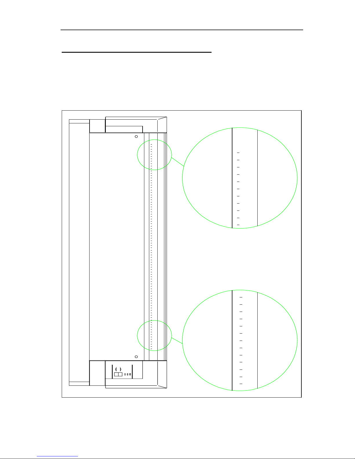
Original’s Insertion Slot and Ruler
The original’s insertion slot shown below is marked with a
measurement ruler from 0 to 8.5. The units correspond to the scanwidth setup options in the WIDEimage scanning application dialogs. A
a second centered ruler is positioned on top, for optional centered
paper loading with standard sizes.
0
DIAGNOSTIC
POWER
WAIT
1.0 2.0 4.03.0 5.0 6.0 7.0 8.0
0 1.0
8.0
Figure 3-2 Original's Insertion Slot and Ruler
Page 18

Operating Modes 4-1
4. Operating Modes
The Full Scale Scanners work in three operating modes:
• Line mode (bitmapped, 2-level)
• Graytone mode (256 graytones)
• Photo mode (halftone dither)
4.1 Line Mode
In this mode, the Full Scale Scanner will output each scanned pixel as
a single bit, either black (1) or white (0) depending on whether its gray
level is below or above the threshold level.
For CAD usage : The distance (both horizontal and vertical) between
each pixel at different resolutions* is given below:
200 dpi: 0.1270 mm
300 dpi: 0.0846 mm
400 dpi: 0.0635 mm
600 dpi: 0.0423 mm
800 dpi: 0.0317 mm
1200 dpi: 0.0212 mm
*Lower and higher resolutions are also available.
The resolution in dpi is always set from the WIDEimage application.
The scan-width is likewise set from WIDEimage, measured by the
ruler units printed on top of scanner near the original’s insertion slot.
Insertion (loading) alignment of the original can be either left side
aligned or centered. Left or center loading is selected through
WIDEimage. The lower (front) ruler is used with side-aligned loading
(the ruler with zero at its left side), and the upper ruler is used with
centered loading.
Page 19

4-2 Operating Modes
The following table shows the number of pixels per scan line resulting
from various combinations of resolution and scan-width on the sidealigned (lower) ruler:
Resolution: 600 dpi 400 dpi 300 dpi 200 dpi
Scanwidth:
8.5 21,600 14,400 10,800 7,200
8.0 20,352 13,568 10,176 6,784
6.0 15,240 10,160 7,620 5,088
4.0 10,176 6,784 5,088 3,392
3.0 7,620 5,080 3,810 2,544
2.0 5,088 3,392 2,544 1,696
The following table shows some common drawing widths and their
required scan-width settings:
Scan- Original Drawing Width*:
width:
Minimum media size of the FSS 6.0"/152mm
1.4 Minimum Scan-Width (A5) 6.0"/152mm
2.0 A-Size (letter) and approx. A4 8.5"/216mm
2.6 B-Size (11") 11.0"/280mm
2.8 A3 (297mm) 11.9"/302mm
3.0 Approx. A3 and approx. B-Size 12.7"/323mm
3.9 A2 (420mm) 16.5"/420mm
4.0 C-Size and approx. A2 17.0"/430mm
5.2 D-Size (22") 22.0"/560mm
5.5 A1 (594mm) 23.3"/592mm
6.0 Approx. A1 and approx D-Size 25.4"/646mm
7.8 A0 (841 mm) 33.1"/840mm
8.0 E-Size and approx. A0 34.0"/862mm
8.5 Maximum Scan-Width of the FSS 36.0"/914mm
Maximum Media size of the FSS 40.0"/1016mm
*The required setting for an original drawing can be measured when
the originals are inserted into the FSS using the ruler printed on top of
the original insertion slot on the Full Scale Scanner.
Page 20

Operating Modes 4-3
4.2 Graytone Mode
In Graytone mode, the actual gray level of each pixel is scanned; 256
levels are recognized, corresponding to 1 Byte (8 bits) per pixel. This
results in graytone files that are 8 times larger than uncompressed
files scanned in Line mode at the same resolution. For example, an ESize drawing scanned in Graytone mode at 300 dpi has a file size of
150 MByte, compared with typical 0.4 -1.0 MByte for a compressed file
in Line mode).
4.3 Photo Mode
In Photo mode, the gray levels of the scanned pixels are converted
into halftones by dithering. This results in very high density Line mode
files that are many times larger than uncompressed files scanned in
Line mode at the same resolution.
Page 21
Installation 5-1
5. Installation
The Full Scale Color Scanner should be placed on a table in such a
way that the front of the machine overhangs the table’s edge by
approximately 1 cm. This ensures that the scanned original can hang
freely from the exit slot at the front of the machine. The table should be
placed a few centimeters from the wall, to allow large sized originals to
hang down freely behind the table. You can also place the FSS
scanner on the specially designed stand-alone floor stand which can
be purchased separately.
Important: Before connecting the power cord to an electrical outlet,
ensure that the voltage selector switch (just above the mains inlet) is
set to the correct voltage.
Make sure that power is turned off, and connect the SCSI cable that
came with your interface kit to one of the two SCSI connectors found
at the back of the Full Scale Color Scanner.
If the scanner is the last device on the SCSI bus, turn on the built-in
active SCSI terminator (see Scanner SCSI DIL-switch setup),
otherwise make sure it is turned off.
You must install the SCSI interface board on your PC. The SCSI
interface board is part of your interface kit that came with your
scanner. Read carefully the following sections and the documentation
that came with interface kit. If your PC already has a built in ASPI
compatible SCSI board you might be able to use that instead. For best
performance, we strongly recommend that you use the board
delivered with the Full Scale Color Scanner.
For UNIX workstations with a built-in SCSI interface, simply turn power
off and connect the scanner SCSI cable.
Set up the SCSI address of your scanner. See instructions on SCSI
DIL-switch setup at the end of this chapter.
Install the WIDEimage scanner software. Installation instructions are
described in the WIDEimage User Manual.
Page 22

5-2 Installation
5.1 Installation of the SCSI board in the PC.
1. Set the PC-system unit power switch to OFF.
2. Set any external option power switches to OFF (such as printers,
displays etc.).
3. Unplug the PC-system unit and all other options from the wall outlet.
4. Remove the cover of your computer to expose the expansion slots.
5. Align and insert the SCSI host adapter board into an empty slot, and
use the expansion slot panel screw to secure the host adapter to the
computer frame.
6. Connect the SCSI cable from the FSS Scanner to the connector on
the SCSI board back panel.
7. Set the scanner DIL Switch as described overleaf in the section:
"Scanner SCSI address setup ".
For further installation description and installation of SCSI driver*
please see the documentation that came with your interface kit.
*Note: SCSI driver installation will be dependent on your Windows
operating system.
5.2 Installation Verification
Install the WIDEimage program as described in the WIDEimage User
Guide that came with the software package.
Run the Height Adjustment of the CCD Cameras as described in this
guide’s Chapter 6 on "Maintenance" to verify the above installation.
Page 23

Installation 5-3
5.3 Scanner DIL-switch Setup
The DIL-switch is used for setting up the scanner’s SCSI connection
port, and for selection of the “Scanner test” modes and the “Scanner
forced boot start up” mode.
Turn off the power to the computer and scanner when setting the SCSI
device number, as the switch settings are only read from the DILswitch during the scanner’s power up.
Set up the SCSI device no. on the DIL-switch found besides the SCSI
connectors on the scanner to an unused SCSI device address no.
according to the table below:
Switch no:
1 2 3 4 5 6 7 8
SCSI device no. 0
ON ON ON X
X X X X
SCSI device no. 1
OFF ON ON X
X X X X
*SCSI device no. 2
ON OFF ON ON OFF OFF OFF OFF
SCSI device no. 3
OFF OFF ON X
X X X X
SCSI device no. 4
ON ON OFF X
X X X X
SCSI device no. 5
OFF ON OFF X
X X X X
SCSI device no. 6
ON OFF OFF X
X X X X
SCSI device no. 7
OFF OFF OFF X
X X X X
Built-in SCSI termination
X X X
ON X
X X X
No Synchronous transfer
X X X X
OFF X
X X
No disconnect
X X X X X
OFF X
X
Force boot start up
X X X X X X
OFF X
Continuous test mode
X X X X X X X
OFF
* Factory Default X: Insignificant
If the scanner is the last device on the SCSI bus, make sure the builtin active SCSI termination is turned on (switch 4 above). If it is not the
last device make sure switch 4 is turned off (see following section on
SCSI termination for details).
Make sure that none of the troubleshooting and test switches are on
(switches 5, 6, 7 and 8).
Page 24

5-4 Installation
Turn on power to the computer and the scanner, and verify the
installation.
Description of the troubleshooting and test switches:
Switch 5. No synchronous transfer: Disables SCSI synchronous
transfer mode (reverts to asynchronous transfer). Use this mode only
for tests as it slows the scanner down.
Switch 6. No disconnect: Disables the SCSI disconnect command.
Use this mode only for tests as it slows the scanner down.
Switch 7. Force boot start up: If a malfunction occurred during an
update of the scanner firmware, this switch forces the scanner into
firmware boot mode, enabling you to download the firmware again.
Switch 8. Continuous test mode: The continuous test mode is only
used for maintenance and renders the scanner inaccessible.
Page 25
Installation 5-5
5.4 SCSI Termination on FSS Scanners
The FSS scanners have a built in active SCSI termination that works
better than a passive terminator at the high transfer rates such as
performed by this scanner.
The built in active termination is enabled by setting switch 4 on the
SCSI switch to ON and disabled by setting it to OFF.
Note: Never set switch 4 to ON and use a terminator block at the
same time.
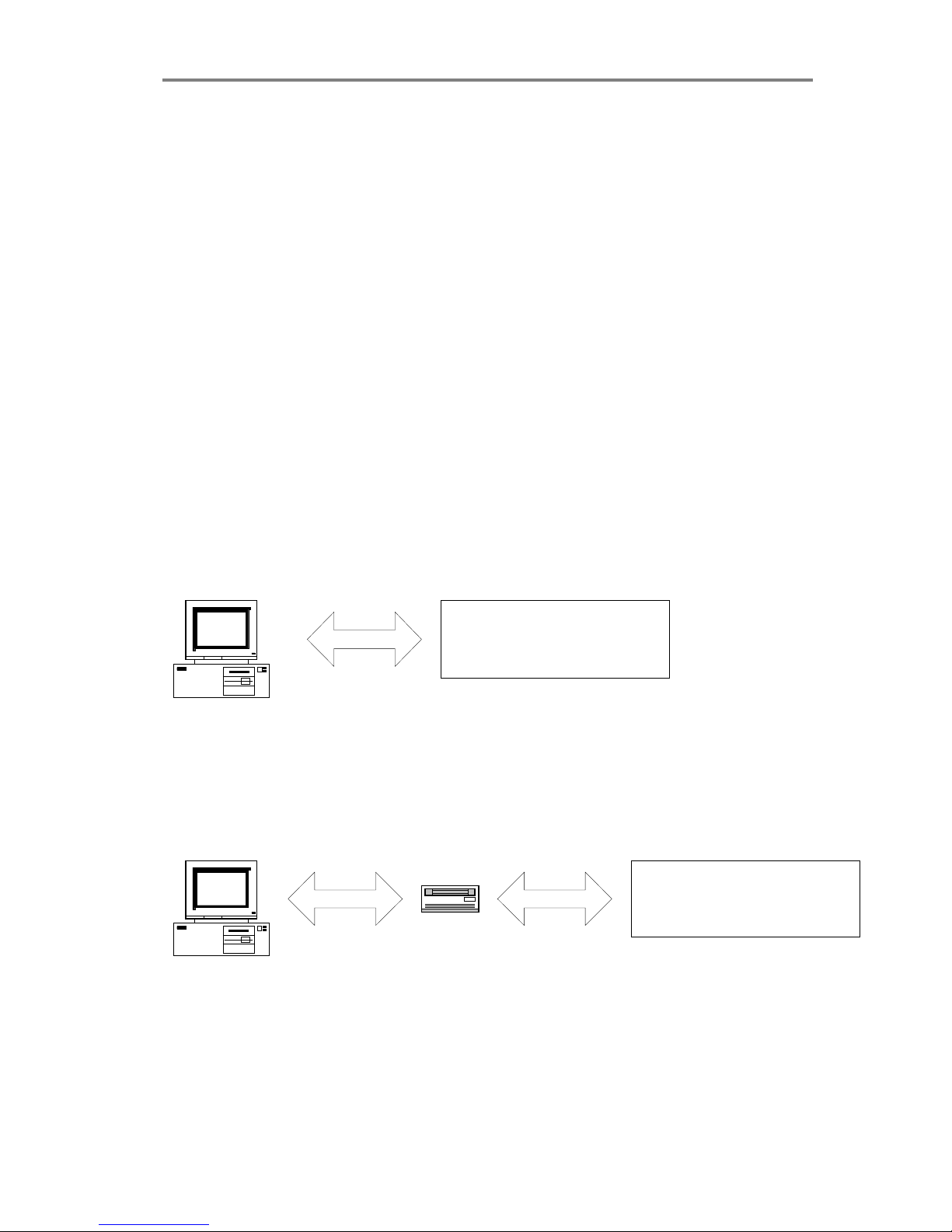
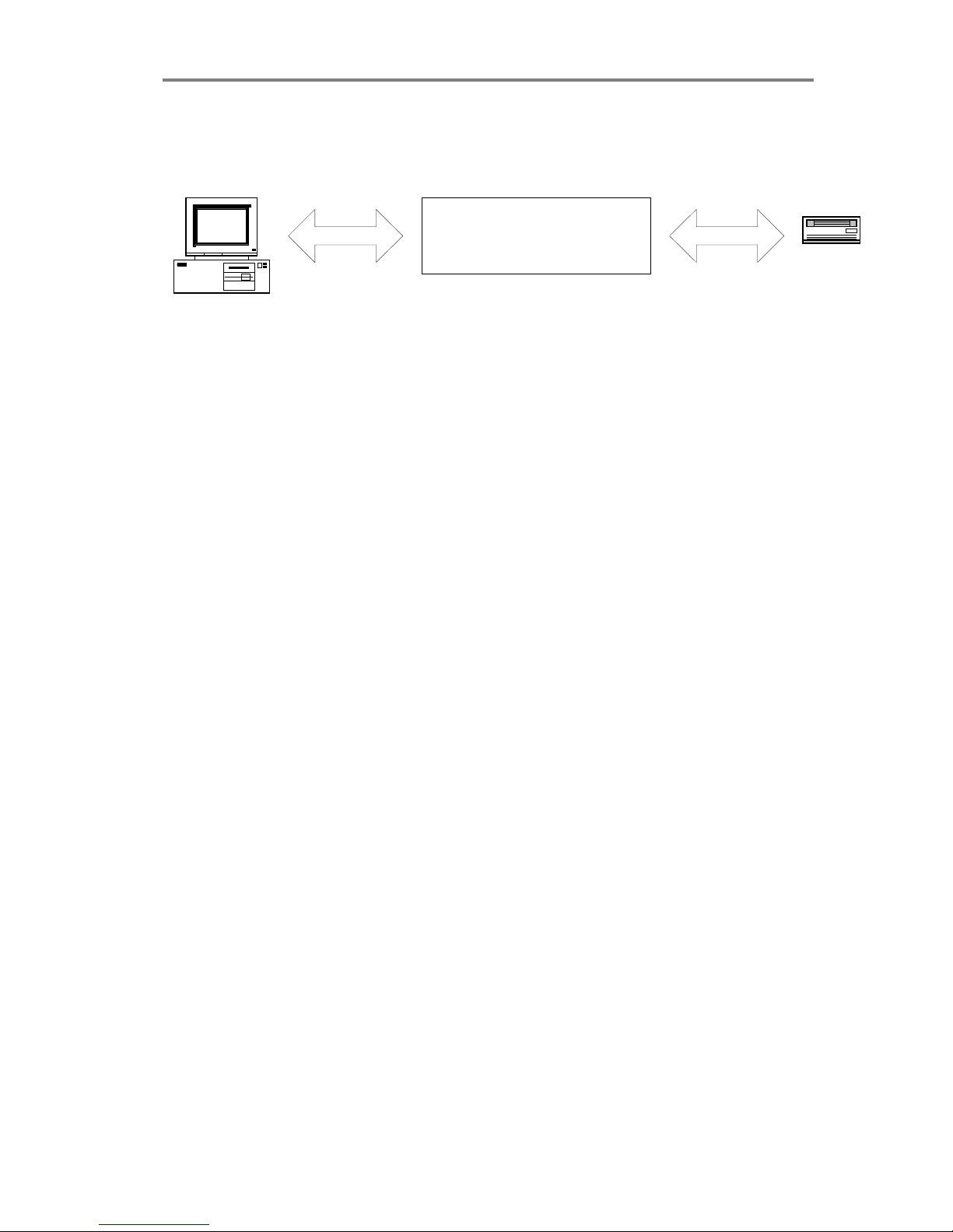
The following 3 scenarios shows how to terminate the SCSI bus
correctly:
A. The Scanner is the only external device on the SCSI bus
Host Computer
SCSI SCANNER
Switch 4 must be ON
B. The Scanner is the last device on the SCSI bus
SCANNER
Switch 4 must be ON
Host Computer
SCSI
CD-ROM
SCSI
Page 26
5-6 Installation
C. The Scanner is not the last device on the SCSI bus
SCANNER
Switch 4 must be OFF
Host Computer
SCSI
CD-ROM
SCSI
Must be
terminated
Note: If the scanner is connected to an existing SCSI controller board
that is used together with an internal SCSI device (f.ex. a hard
disk), make sure that the on-board SCSI termination is removed
before attaching the scanner.
.
Page 27
Maintenance 6-1
6. Maintenance
The main maintenance tasks involve :
• Cleaning the original’s scanning area
• Adjusting the height of the CCD-cameras at regular intervals
6.1 Cleaning the Original’s Scanning Area
Make sure you turn the power switch OFF and disconnect the power
plug when cleaning the original’s scanning area .
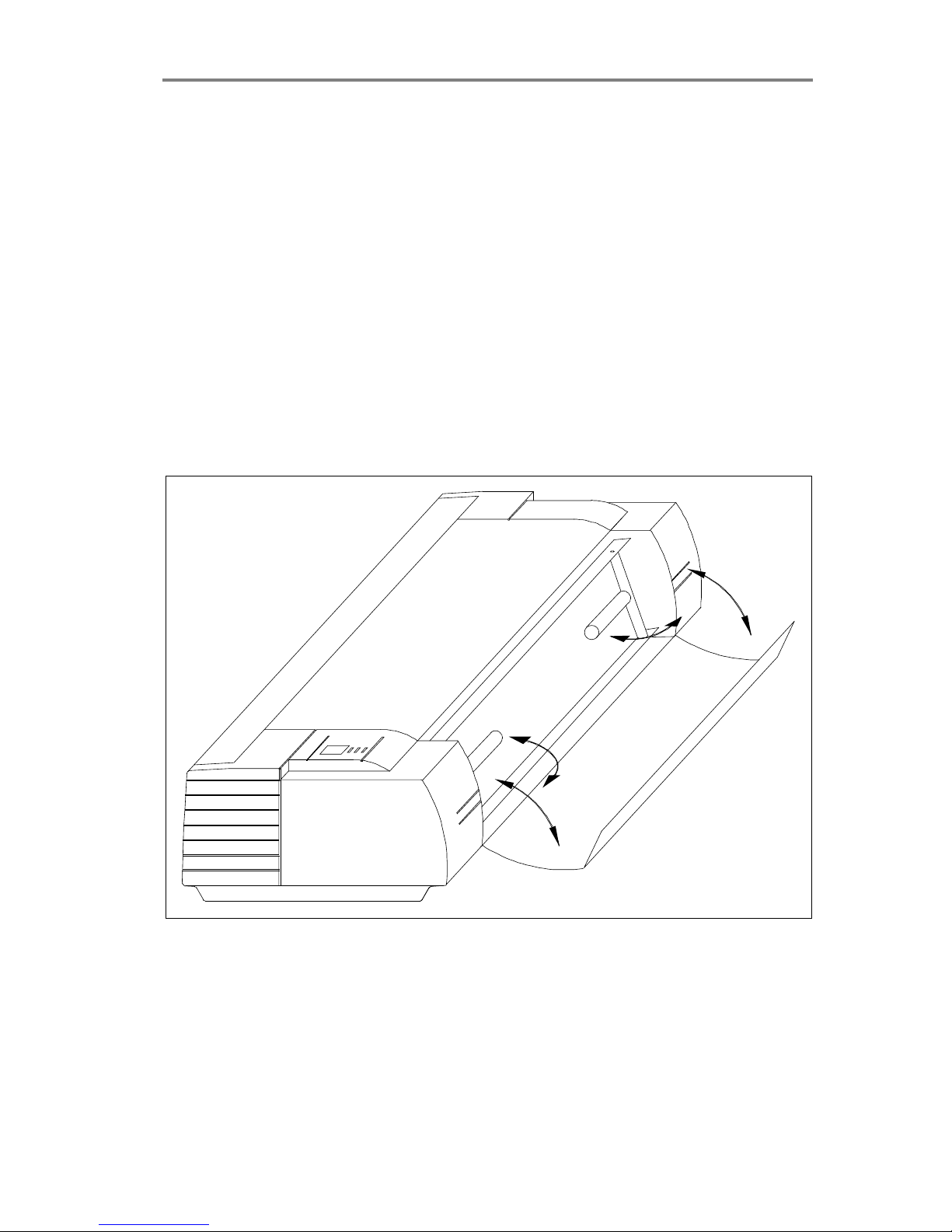
1. Open the scanner’s front cover by gently pulling at its top.
2. Remove the original’s guide plate and gently wipe the glass plate
and the white area on the original’s guide plate until they are clean.
Figure 6-1 Opening the front cover
Page 28
6-2 Maintenance
6.2 Adjusting the height of the CCD Cameras
The steps for camera height adjustment vary from model to model.
Find your model in the sections below:
The FSS8300 :
1. Insert the Height Alignment Chart delivered with the scanner into
the original’s insertion slot and press the Paper Feed/Forward key.
In WIDEimage select a scan-width size of 8.5, and start
prescanning by clicking WIDEimage’s Forward button in the scan
dialog. Click Halt to stop the prescanning operation when it comes
over the horizontal lines in the chart. Set the application’s "detail
window" so you view the area in the middle of the "overview
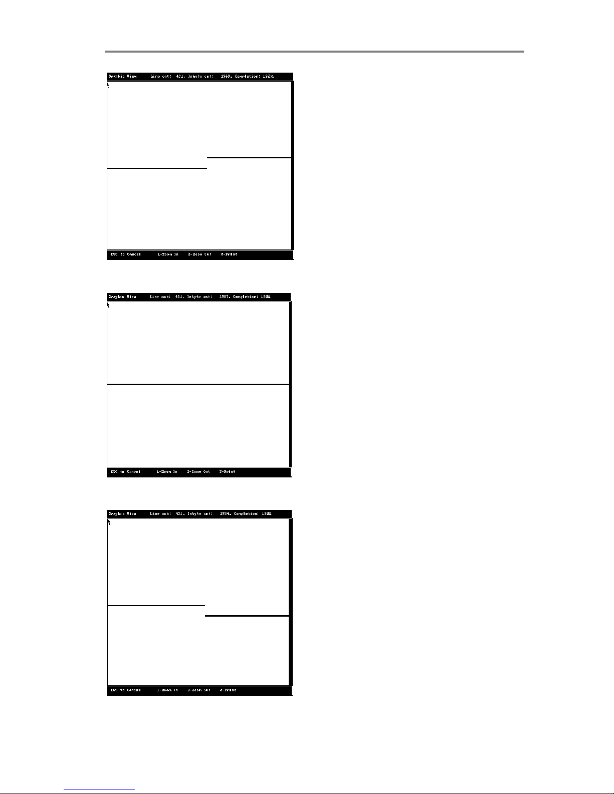
window". The "detail window" should show an image similar to one
of the three figures overleaf.
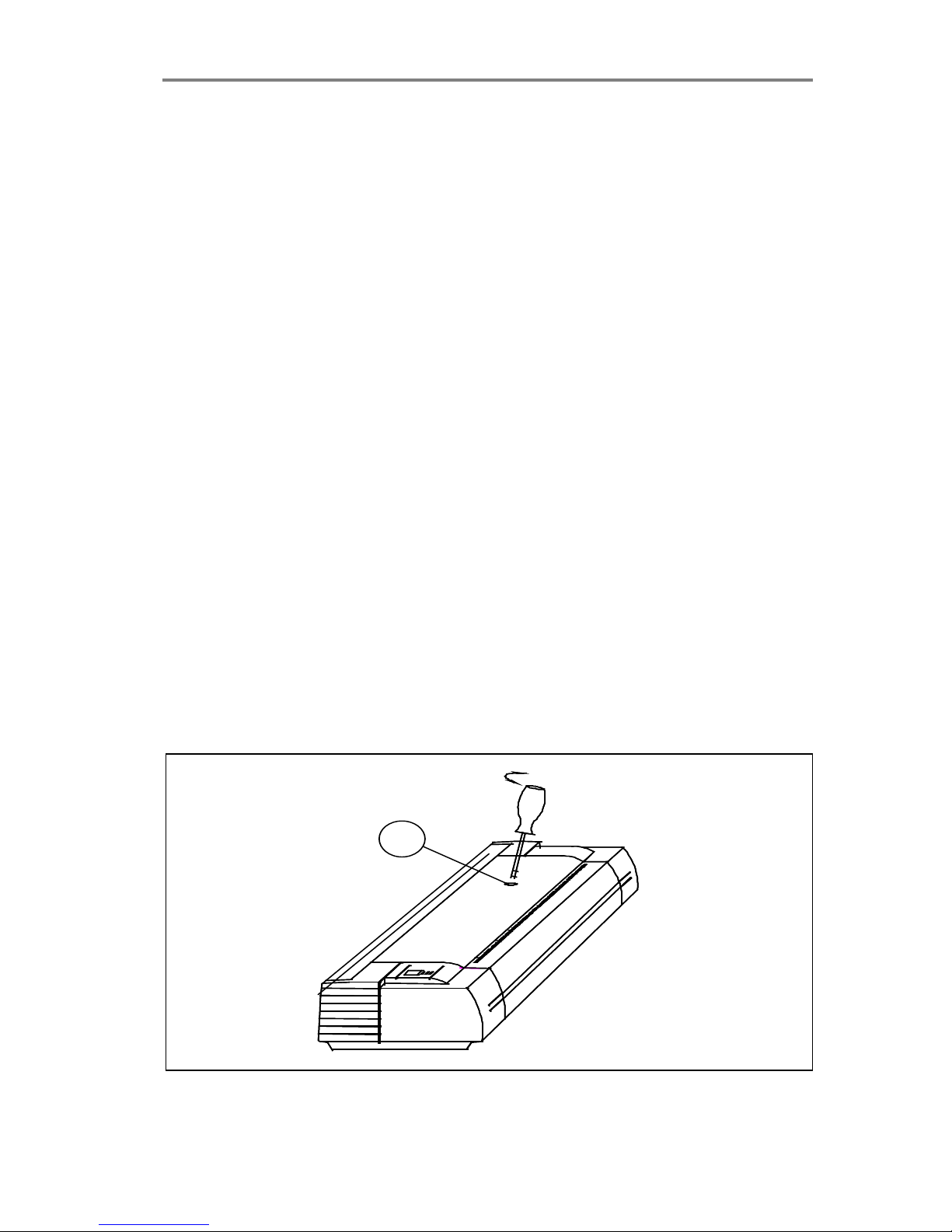
2. Use a slim screw-driver to turn the height adjustment screw
through the hole (1) on the top of the FSS (see figure overleaf).
Screw clockwise or counter-clockwise so that the lines from the
left and right CCD-Cameras make a continuous line on the ”downscans” on the screen:
Clockwise: Line at right side of screen moves down.
Counter Clockwise: Line at right side of screen moves up.
Note: To omit angle errors, only judge camera height adjustments on
the repeated ”down-scans” on the screen.
1
Figure 6-2 Camera Height Adjustment
Page 29
Maintenance 6-3
Figure 6-3 Height adjustment (turn clockwise)
Figure 6-4 Height Adjustment (correctly aligned)
Figure 6-5 Height Adjustment (turn counter clockwise)
Page 30

6-4 Maintenance
FSS12300 Models:
1. For adjusting the left CCD Camera (when facing the front of the
scanner), follow the procedure given above for the FSS8300
models, but select a "detail window" centered about one-third in
from the left in the "overview window".
Clockwise: Line at Left side of Screen moves Down.
Counterclockwise: Line at Left side of Screen moves Up.
2. For adjusting the right CCD Camera, follow the procedure given
above for the FSS8300 models, but select a "detail window"
centered about two-third in from the left in the "overview window".
Clockwise: Line at Right side of Screen moves Down.
Counterclockwise: Line at Right side of Screen moves Up.
FSS18300 Models:
1. For adjusting the left CCD Camera (when facing the front of the
scanner), follow the procedure given above for the FSS8300
models, but select a "detail window" centered about one-quarter in
from the left in the "overview window".
Clockwise: Line at Left side of Screen moves Down.
Counterclockwise: Line at Left side of Screen moves Up.
2. For adjusting the third CCD Camera (second adjustment knob)
follow the procedure given above for the FSS8300 models, but
select a "detail window" centered about halfway in from the left in
the "overview window".
Clockwise: Line at Right side of Screen moves Down.
Counterclockwise: Line at Right side of Screen moves Up.
3. For adjusting the right CCD Camera, follow the procedure given
above for the FSS8300 models, but select a "detail window"
centered about three-quarter in from the left in the "overview
window".
Clockwise: Line at Right side of Screen moves Down.
Counterclockwise: Line at Right side of Screen moves Up.
Remember: To omit angle errors, only judge the camera height on the
repeated ”down-scans” on the screen .
Page 31

Maintenance 6-5
6.3 Camera Out of Light Error
If both the Diagnostic and Wait (Warm Up) indicators start blinking on
the Operator Panel, then one of the CCD cameras has moved out of
range while making adjustments or during transportation. This means
that the camera receives an inadequate amount of light.
The number of flashes per second on the Wait indicator shows which
camera is “out of light” and needs readjustment. The camera numbers
given below are indexed starting from the left side of the machine
when facing its front:
Camera 1: 1 flash per period.
Camera 2: 2 flashes per period.
Camera 3: 3 flashes per period.
Camera 4: 4 flashes per period.
Before proceeding with the CCD camera height adjustment
procedures, carry out the following for the indicated camera that is “out
of light”:
1. Turn its height adjustment screw completely clockwise.
2. Turn its height adjustment screw one quarter of a turn counter
clockwise
3. Turn the scanner’s power off, and then on. If the error is still
displayed by the blinking indicators, then repeat step 2 and 3.
FSS4300: Camera not user adjustable.
FSS8300: First Camera (1), not user adjustable.
FSS12300: Middle Camera (2), not user adjustable.
FSS18300: Second Camera (2) from the left, not user adjustable.
After clearing the "Camera out of light error", proceed with the CCD
camera height adjustments described in the previous section.
Page 32

A: Specifications 7-1
7. Appendix A: Specifications
To ensure state of the art products and design, Contex reserves the
right to change specifications at any time.
Model FSS18300
DSP
FSS12300
DSP
Sensors: Quadruple CCDs Triple CCDs
32.000 pixels 24.000 pixels
Image Resolution (dpi):
1800, 1600, 1400, 1200, 1000, 800
1200, 1000, 800, 600, 500, 400, 300
600, 500, 400, 300 200, 150, 150, 75,
200, 150, 75, 50 & 25 50 & 25
Image Size:
Media Width: 6.0 to 40.0" 6.0 to 40.0"
(1016mm.) (1016mm.)
Scan Width: 36 Inches 36 Inches
(max.) (914 mm) (914 mm.)
Scanner Measurements (inches/mm):
Width: 47.25"/1200 47.25"/1200
Depth: 15.0"/380 15.0"/380
Height: 7.9"/200 7.9"/200
Power:
Consumpt.: 130W
Voltage: 100/115/220/240V-50/60Hz
Weight: 44 kg. 43 kg.
Light Source: Stabilized Fluorescent Lamp
Interface: Industry standard SCSI-2 I/F
Graylevels: Up to 256 levels recognized (1Byte, 8Bits
per pixel).
Window Scan: Adjustable Horizontal and Vertical Offset
and scan-window size.
Image Processing:
Digital Signal Processor, 2D-Adaptive Threshold.
On-line threshold, deskewing, despeckling and holefilling.
Individual pixel adaptive ampl. correction and graytone
interpolation. Image rotation, alignment, mirroring and reverse.
On-screen view, zoom, and print functions.
More than fifty industry standard image file formats supported.
Side-aligned or centered insertion of the original.
Page 33

7-2 A: Specifications
Model FSS8300
DSP
FSS4300
DSP
Sensors: Dual CCDs Single CCD
16.000 pixels 8.000 pixels
Image Resolution (dpi):
800, 600, 500,
400, 300, 200, 400, 300, 200,
150, 75, 50 & 25 150, 75, 50 & 25
Image Size:
Media Width: 6.0 to 40.0" 6.0 to 40.0"
(1016mm.) (1016mm.)
Scan Width: 36 Inches 36 Inches
(max.) (914 mm) (914 mm.)
Scanner Measurements(inches/mm):
Width: 47.25"/1200 47.25"/1200
Depth: 15.0"/380 15.0"/380
Height: 7.9"/200 7.9"/200
Power:
Consumpt.: 130W
Voltage: 100/115/220/240V-50/60Hz
Weight: 42 kg. 42 kg.
Light Source: Stabilized Fluorescent Lamp
Interface: Industry standard SCSI-2 I/F
Graylevels: Up to 256 levels recognized (1Byte, 8Bits
per pixel).
Window Scan: Adjustable Horizontal and Vertical Offset
and scan-window size.
Image Processing:
Digital Signal Processor, 2D-Adaptive Threshold.
On-line threshold, deskewing, despeckling and holefilling.
Individual pixel adaptive ampl. correction and graytone
interpolation.
Image rotation, alignment, mirroring and reverse.
On-screen view, zoom, and print functions.
More than fifty industry standard image file formats supported.
Side-aligned or centered insertion of the original.
Page 34

A: Specifications 7-3
Model FSS8300PLUS
DSP
Sensors: Dual CCDs
16.000 pixels
Image Resolution (dpi):
25 to 800
Setable in
1 dpi incre-
ments.
Image Size:
Media Width: 6.0 to 40.0"
(1016mm.)
Scan Width: 36 Inches
(max.) (914 mm)
Scanner Measurements(inches/mm):
Width: 47.25"/1200
Depth: 15.0"/380
Height: 7.9"/200
Power:
Consumpt.: 130W
Voltage: 100/115/220/240V-50/60Hz
Weight: 42 kg.
Light Source: Stabilized Fluorescent Lamp
Interface: SCSI-2 I/F (Workstation)
Graylevels: Up to 256 levels recognized (1Byte, 8Bits
per pixel).
Window Scan: Adjustable Horizontal and Vertical Offset
and scan-window size.
Image Processing:
High Scanning speed (dependent on dpi setting and host)
Digital Signal Processor, 2D-Adaptive Threshold.
Advanced "Area Diffusion Logic (ADL)" preserves tones of grey
in copies, maintains compact print-ready files.
On-line threshold, deskewing, despeckling and holefilling.
Individual pixel adaptive ampl. correction and graytone
interpolation.
Image rotation, alignment, mirroring and reverse.
On-screen view, zoom, and print functions.
More than fifty industry standard image file formats supported.
Side-aligned or centered insertion of the original.
Page 35

B: Regulations 8-1
8. Appendix B: Regulations
8.1 FCC Regulations
This equipment has been tested and found to comply with the limits for
a class A digital device, pursuant to Part 15 of the FCC Rules. These
limits are designed to provide reasonable protection against harmful
interference when the equipment is operated in a commercial
environment. This equipment generates, uses, and can radiate radio
frequency energy and, if not installed and used in accordance with the
instruction manual, may cause harmful interference to radio
communications. Operation of this equipment in a residential area is
likely to cause harmful interference in which case the user will be
required to correct the interference at his own expense.
Page 36
8-2 B: Regulations
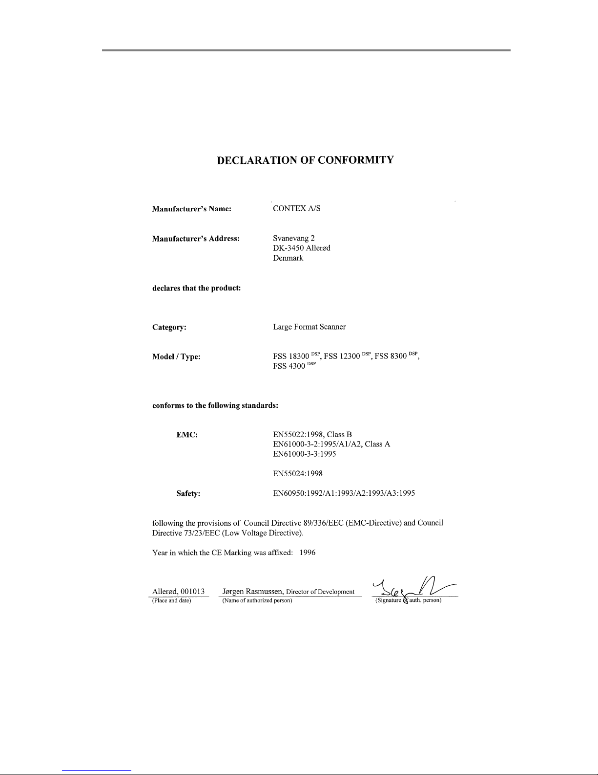
8.2 EU Regulations
Page 37

C: License 9-1
9. Appendix C: Program License Agreement
You should carefully read the following terms and conditions before opening the
diskette package. Opening the diskette package indicates your acceptance of the terms
and conditions. If you do not agree with them you should promptly return the package
unopened, and your money will be refunded.
Contex provides this program and licenses its use. You assume responsibility for the
selection of the program to achieve your intended results, and for the installation, use
and results obtained from the program.
License:
1. You may use the program on a single machine.
2. You may modify the program and/or merge it into another program for your use on
the single machine.
3. You may copy the program into any machine readable or printed form for backup
or modification purposes in support of your use of the program on the single
machine.
4. You may not use, copy, modify or transfer the program, or any copy, modification
or merged portion, in whole or in part, to another party, except as expressly
provided for in this license. If you do so you terminate your license.
Term:
The license is effective until terminated. You may terminate it at any time by
de¬stroying the program together with all copies. The license will also terminate upon
conditions set forth elsewhere in this Agreement or if you fail to comply with any term or
condition of the Agreement. You agree upon such termination to destroy the program
together with all copies, modifications and merged portions in any form.
Limited Warranty:
This program is provided as is, without warranty of any kind, either stated or implied,
including but not limited to the implied warranties of merchantability and fitness for a
particular purpose. The entire risk as to the quality and performance of the program is
with you. Should the program or hardware provided with the program prove defec¬tive,
you (and not Contex or an authorized dealer) assume the entire cost of all necessary
servicing, repair or correction.
Some states do not allow the exclusion of implied warranties, so the above exclusion
may not apply to you. This warranty gives you specific legal rights; you may also have
other rights which vary from state to state. Contex does not warrant that the functions
or the operation of the program will be uninterrupted or error free.
However, Contex warrants the diskette on which the program is furnished to be free
from defects in materials and work¬manship under normal use for a period of one (1)
year from the date of delivery to you, as evidenced by a copy of your receipt.
Limitations of Remedies:
Contex's entire liability and your exclusive remedy shall be:
Page 38

9-2 C: License
The replacement of any diskette not meeting the Contex "Limited Warranty" and which
is returned to Contex or an authorized Contex dealer with a copy of your receipt, or
If Contex or the dealer is unable to deliver a replacement diskette which is free of
defects in materials or workmanship, you may terminate this Agreement by returning
the program and your money will be refunded.
In no event will Contex be liable to you for any damages including any lost profits, lost
savings, or other incidental or consequential damages arising out of the use or inability
to use such program, even if Contex or an authorized Contex dealer has been advised
of the possiblity of such damages, or for any claim by any other party. Some states do
not allow the limitation or exclusion of liability for incidental or concequen¬tial damages,
so the above limitation or exclusion may not apply to you.
General:
You may not sublicense, assign or transfer the license of the program except as
expressly provided in this Agreement. Any attempt otherwise to sublicense, assign or
transfer any of the rights, duties or obligations hereunder is void.
This Agreement will be governed by the laws of Denmark. Should you have any
questions concerning this Agreement, you may contact Contex.
You acknowledge that you have read this Agreement, understand it, and agree to be
bound by its terms and conditions. You further agree that it is the complete and
exclusive statement of the agreement, oral or written and any other communications
between us relating to the subject matter of this Agreement.
CONTEX
Page 39

D: Safety 10-1
10. Appendix D: Important Safety Instructions
Read all of these instructions and save them for later use. Please
follow all warnings and instructions marked on the scanner.
A. Do not place the scanner on an unstable surface, stand, cart, or
table. Serious damage can be caused if the unit falls.
B. Turn off all power to the unit before cleaning. Do not use liquid
cleaners or aerosol cleaners.
Use a damp cloth for cleaning.
C. The scanner should be operated from the type of power source
indicated on the marking label. If you are not sure of the type of power
available, consult your dealer or local power company.
D. The scanner is equipped with a three-wire grounding type plug. This
plug will fit only into a grounding-type power outlet. This is a safety
feature. If you are unable to insert the plug into the outlet, contact your
electrician to replace your obsolete outlet. Do not defeat or ignore the
purpose of the grounding-type plug.
E. Do not allow anything to rest on the power cord. Do not locate the
scanner where people may walk over or step on the cord.
F. If an extension cord is used with the scanner, make sure that the
total of the ampere ratings of the products plugged into the extension
cord does not exceed the extension cord ampere rating. Also, make
sure that the total of all products plugged into the wall outlet does not
exceed 15 amperes.
G. Slots or openings in the cabinet at the back or bottom are provided
for ventilation. These are to ensure reliable operation of the product
and to protect it from overheating. The openings must never be
blocked or covered. The openings should never be blocked by placing
the unit on a bed, sofa, rug, or other similar soft surface. This product
should never be placed near or over a radiator or heat register. This
product should not be placed in a built-in installation unless proper
ventilation is provided.
Page 40

10-2 D: Safety
H. Never push objects of any kind into the scanner through cabinet
slots since they may touch dangerous voltage points or short out parts
that could result in a fire or electrical shock. Avoid spilling liquid of any
kind on the scanner and keep liquids far from the unit.
I. Do not attempt to service the scanner yourself. Any covers that
require tools to get opened or removed, may expose you to dangerous
voltage points or other risks. Refer all servicing in those compartments
to authorized service personnel.
J. Unplug the scanner from the wall outlet and refer servicing to
authorized service personnel under the following conditions:
• When the power cord or plug is damaged or frayed.
• If liquid has been spilled into the scanner.
• If the scanner has been exposed to rain or water.
• If the scanner does not operate normally when operating
instructions are followed. Adjust only those controls that are
covered by the operating instructions since improper adjustment
of other controls may result in damage and will often require
extensive work by a qualified technician to restore this product to
normal operation.
• If the scanner has been dropped or the cabinet has been
damaged.
If the scanner exhibits a distinct change in performance, indicating a
need for service
Page 41

E: Index 11-1
11. Appendix E: Index
2D-Adaptive Threshold.....1-2, 7-1
Aerosol cleaners.................... 11-1
Alignment ................................7-1
Area Diffusion Logic ......... 1-1, 7-3
Blueprint .................................. 1-2
Camera out of Light error ........6-5
CCD-Cameras......................... 6-1
Computer Aided Design .......... 1-2
Desk Top Publishing ...............1-3
Deskewing............................... 7-1
Despeckling............................. 7-1
Device number ........................ 5-3
Diagnostic Indicator................. 3-3
Drawing Archival .....................1-4
Drawing widths ........................ 4-2
EC Regulations .......................9-2
FCC Regulations ..................... 9-1
File formats.............................. 7-1
Format ..................................... 9-2
Glossary .................................. 8-1
Graylevels ...............................7-1
Graytone Mode........................ 4-3
Grounding-type power outlet . 11-1
Height adjustment ............6-2, 6-3
Holefilling................................. 7-1
Image Processing.................... 7-1
Installation ............................... 5-1
Installation verification............. 5-2
Interface ..................................7-1
Light Source ............................ 7-1
Line Mode................................ 4-1
Liquid cleaners ...................... 11-1
Media Width ............................7-1
Mirroring .................................. 7-1
Mylar........................................ 1-2
On-line threshold..................... 7-1
Operating Modes..................... 4-1
Operator Panel ........................ 3-1
Original Scanning Area ...........6-1
Paper Feed/Forward Key ........ 3-1
Paper Reverse Key ................. 3-1
Photo Mode ............................. 4-3
Pixel adaptive ampl. correction7-1
Power ...................................... 7-1
Power On indicator.................. 3-1
Power source ........................11-1
Program License Agreement. 10-1
Ready indicator ....................... 3-1
Resolution .................2-1, 4-2, 7-1
Reverse ................................... 7-1
Rotation ................................... 7-1
Ruler........................................ 3-4
Safety .................................... 11-1
Satellite Photo ......................... 1-4
Scan Width.............................. 7-1
Scanner DIL-switch ................. 5-3
Scanner Measurements .......... 7-1
Scan-width settings ................. 4-2
SCSI .... 2-3, 5-1, 5-2, 5-3, 5-4, 5-5
SCSI Termination .................... 5-5
Sepias .....................................1-2
Vellum .....................................1-2
Wait Indicator (Warm up) ........ 3-3
Weight ..................................... 7-1
 Loading...