

Page 1
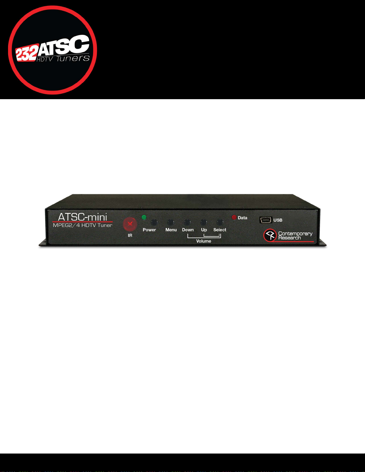
ATSC-mini HDTV Tuner
QIP-D Installation Manual
Product Manual
972-931-2728 | 888-972-2728 | www.contemporaryresearch.com
Page 2

Contents
Overview ............................................................................................................................................................................................. 3
Installing the ATSC-mini ....................................................................................................................................................................... 4
ATSC-mini Control and Setup .............................................................................................................................................................. 4
Front Panel Operation ......................................................................................................................................................................... 5
Rear Panel Connections ....................................................................................................................................................................... 6
Setup Notes ......................................................................................................................................................................................... 7
On-Screen Text Menus ........................................................................................................................................................................ 8
HD2-RC IR Remote .............................................................................................................................................................................10
On-Screen Graphical AV Menus ........................................................................................................................................................11
Web Pages .........................................................................................................................................................................................15
RS-232/Telnet/UDP Control Protocol ...............................................................................................................................................19
Firmware Update ..............................................................................................................................................................................25
ATSC-mini Specifications ...................................................................................................................................................................26
Safety Instructions and Warranty ......................................................................................................................................................28
Page | 2 ATSC-mini HDTV Tuner Product Manual 072022
Page 3

Overview
The Contemporary Research ATSC-mini HDTV Tuner is a full featured ATSC/NTSC HDTV tuner for professional applications. The ATSC-mini
will tune ATSC air, clear QAM cable, and NTSC air and cable channels. The low-profile design allows for mounting behind flat panel displays.
The HDTV tuner supports full 2-way RS-232 control, configuration, and status monitoring via rear panel serial port, IP Telnet, and UDP for
integration with third-party control systems.
Front panel controls are available for channel selection, volume, power, and menu. The unit may also be controlled by the optional HD2-RC
IR remote via the front panel IR sensor or remote IR sensor connected to the rear panel IR port.
On-board web pages allow for remote configuration, control, and monitoring from a web browser.
When used as part of an Ethernet based iCC-Net control system, the tuner will respond to power, channel, and volume commands. The
control interface may be the Display Express Lite application included with an ICE-HE-DXL or IP-DXL Display Control Center, Display Express
software, or a third-party control system.
Features
Tuning
ATSC air and Clear QAM cable channels
NTSC air and cable channels
Air channels 2-69
Cable channels 2-135, Standard, HRC, and IRC
Decoding
MPEG-2 or H.264 digital channels
Supports AC-3, MPEG-1 Layer 2, or AAC audio formats
Supports multiple audio programs
Video
HDMI Type A, Version 1.4b
Output scaling to 480i, 480p, 720p, 1080i, 1080p, and 2160p
Adjustable overscan
Audio
HDMI embedded AC-3 pass-through, PCM Fixed, or PCM Variable
S/PDIF optical digital audio output
Variable analog stereo
Closed Captions
Decodes analog and digital closed captioning
Setup and Control
Control via front panel, optional HD2-RC IR remote, on-board web pages or RS-232 commands
Two-way control via RS-232, Telnet, or UDP
One-way control via ICC-Net UDP commands
CEC control available on HDMI output
Setup via on-screen menus, web pages, or RS-232 commands
Receives iCC-Net protocol control commands over Ethernet for power, channel selection, and volume
Firmware updatable over Ethernet with CR Toolbox software for PC
Page | 3 ATSC-mini HDTV Tuner Product Manual 072022
Page 4

Installing the ATSC-mini
The slim profile of the ATSC-mini allows for mounting behind a flat panel display. The unit may be attached to the flat panel display with
user provided hook and loop fastener adhesive tape or attached to the wall using the mounting ears. The unit may also be set flat on a
suitable shelf or other stable flat surface.
Connect the HDMI output to a video display. Analog and S/PDIF digital audio outputs are available for connection to an amplifier or audio
system processor. Connect a coaxial cable from the CATV or antenna source to the Air/Cable input connector. The ATSC-mini will need to
be connected to an appropriate power source. Power may be supplied from the included PS-12-1.0 power supply or PoE from a compatible
network switch or PoE injector.
Following the completion of the physical installation of the ATSC-mini, a channel scan will need to be performed prior to viewing programs.
The channel scan may be initiated in the on-screen text A/V menu, the on-screen graphical menu, control web page, or via RS-232 or iCC-Net
command.
ATSC-mini Control and Setup
The control and setup functions of the ATSC-mini may be accessible by various methods.
On-Screen graphical and text menus accessible from front panel or optional handheld IR remote
On-board web pages
Two-way RS-232 protocol control and configuration commands via rear panel DB-9 serial port or Telnet
One-way iCC-Net protocol commands delivered over the Ethernet through an ICE-HE-DXL or IP-DXL display control center, Display
Express Server PC, or third-party control system
Page | 4 ATSC-mini HDTV Tuner Product Manual 072022
Page 5
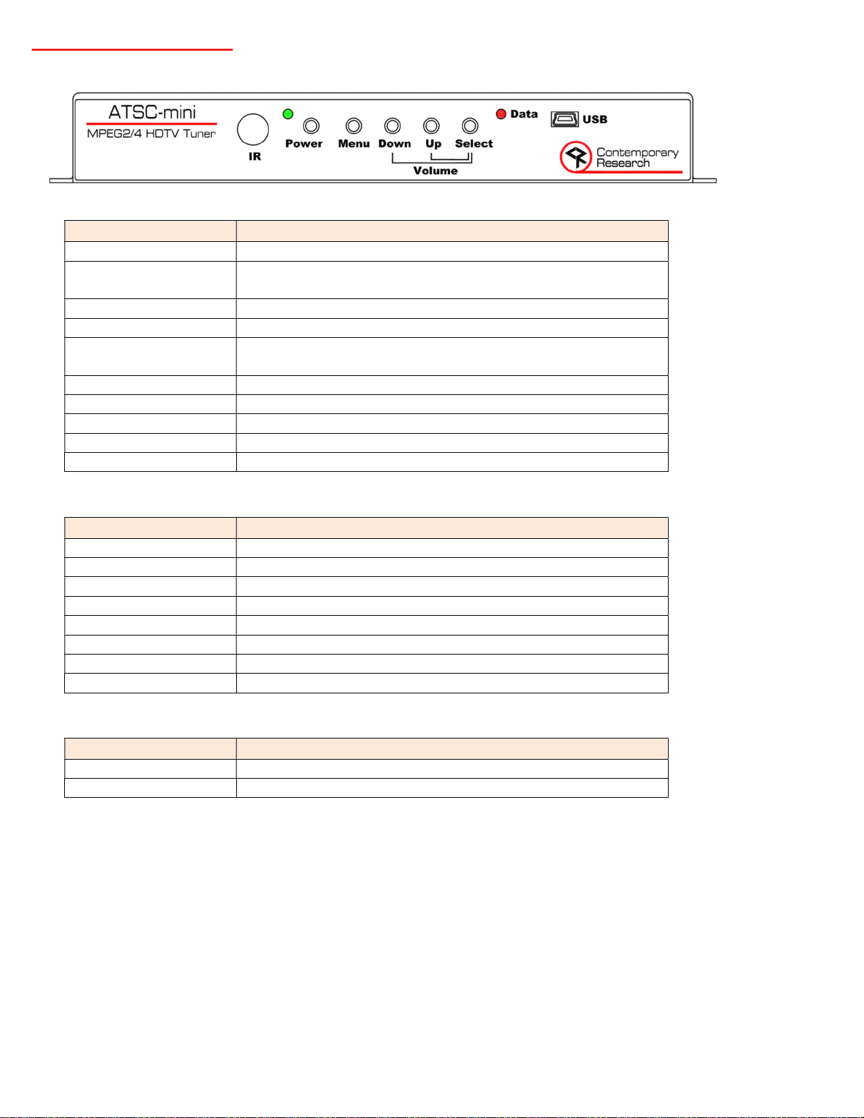
Front Panel Operation
Button
Operation
Mode
Status
Mode
Status
Front Panel Button Operation
Power Toggles On | Off
Menu Push to display on-screen Graphical Audio/Video menu
Hold to display on-screen Text Setup menu
Down
Up Channel Up
Select Push to select menu item
Select + Down Volume Down
Select + Up Volume Up
Down + Up Toggles Audio Mute
Menu + Up Unlocks previously locked buttons until power cycle
Menu + Select Restore factory default video settings
Power LED Operation
Channel Down
Hold to display current IP address on-screen
Red Solid On Unit is Off
Green Solid On Unit is On and channel is locked
Green Slow Blink Unit is On and is searching for signal (1 second on, 1 second off)
Green Fast Blink Powering up (¼ second on, ¼ second off)
Red Flash IR remote button press
Green, Staggered Blink On-screen Menu (Blink-Blink-Pause sequence)
Red Fast Blink Bootloader Mode (uses RS-232 connector)
Red/Green Alternating Firmware Update Mode
Data LED Operation
Red Flash RS-232 Data Transmit
Green Flash RS-232 Data Receive
Page | 5 ATSC-mini HDTV Tuner Product Manual 072022
Page 6
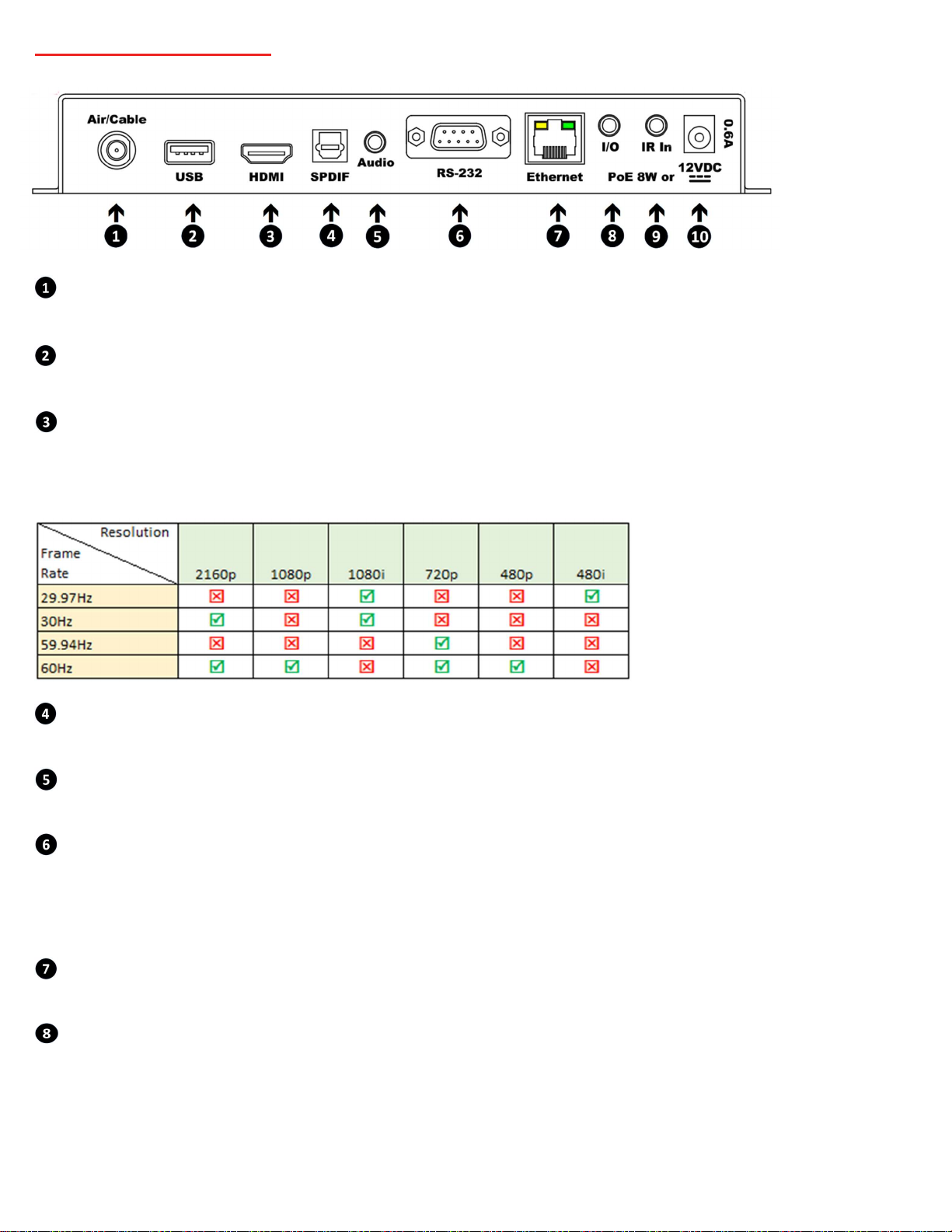
Rear Panel Connections
Air/Cable
“F” female connector for RF Input to tuner.
USB
USB-A service port. May be used for tuner/decoder firmware updates.
HDMI
HDMI receptacle, Type A, Version 1.4b. The output normally automatically detects an HDMI or DVI display. The audio format follows the
digital audio output format setting.
Available Output Formats:
SPDIF
JIS F05 jack for optical S/PDIF digital audio output. The audio format follows the digital audio output format setting.
Audio
3.5 mm TRS jack for variable level stereo analog audio output
RS-232
DB-9 port for RS-232 data link to control system, 1200 to 230K baud, 8 data bits, no parity, 1 stop bit
Pin 2= Data Receive
Pin 3= Data Transmit
Pin 5= Ground
Ethernet
RJ-45 jack, 100Mbps, PoE
I/O
For future use
Page | 6 ATSC-mini HDTV Tuner Product Manual 072022
Page 7

IR In
3.5 mm TRS jack for optional external IR receiver or wired IR from a control system processor.
Tip= +5v DC (50mA max)
Ring= Input
Sleeve= Ground
12VDC
Power input 2.1mm coaxial jack (inside center conductor positive)
Setup Notes
Channel Scan
A channel scan will be required prior to initial use and subsequently following any changes to the received channel line-up. The channel
scan may be initiated in on-screen graphical menu, on-screen text menu or by RS-232 command. The Air or Cable scan mode should be
selected for the intended application prior to initiating the scan.
Tuning Cable Channels
The ATSC-mini will skip encrypted channels automatically during a channel scan.
Air/Cable
The ATSC-mini has separate channel memories for air and cable channels. It is possible to toggle between the two channel memories. A
separate channel scan for each mode will be required. The scan of analog channels may be skipped by pressing Select after the scan has
started.
The Air/Cable mode may be toggled by:
A/C button on optional HD2-RC infrared remote control
A/C button on Control web page
Air/Cable button on A/V web page
Press Menu + Down simultaneously on the front panel
RS-232 command
DVI
The HDMI output is compatible with DVI input devices using an appropriate adaptor cable. DVI mode is normally automatically detected
when Auto is selected in the HDMI-DVI menu. Forced DVI or forced HDMI may be selected from the HDMI-DVI menu.
Audio
All audio outputs are active simultaneously. The audio format options are AC-3, PCM, and PCM variable. The volume level settings do not
affect the level of digital audio when set for AC-3 or PCM. PCM Variable supports volume control on all audio outputs. The analog audio
output will follow the volume level settings and is independent of the audio format selected. If there is no audio, make sure the volume is
all the way up (and not muted). A “motorboat” sound may indicate that the display does not support AC-3, and the mode should be
changed to PCM or PCM variable.
IR Control
Interference from room fluorescent lights can cause problems with IR remote operation. If this occurs, the frequency of the IR may
be changed in the HD2-RC remote. Hold Select and press “9” to set the IR frequency at 57 KHz. Hold Select and press “4” to set the
IR to the normal 38 KHz frequency.
If there is significant IR interference, an IR-RXD Remote Sensor may be required. Cover the front-panel IR sensor to reduce
interference.
Disabling the IR sensor in the configuration settings will disable the front panel IR sensor and the rear panel IR In jack.
The ATSC-mini will respond to a universal remote with the TV type set to Sharp.
Page | 7 ATSC-mini HDTV Tuner Product Manual 072022
Page 8

HDMI CEC Display Control
Button
Function
HDMI CEC may be enabled for controlling display power. HDMI CEC sends standardized control commands over the HDMI cable. CEC
functionality is available in many TVs and displays designed for the consumer market. If control of the TV or display via HDMI CEC is desired,
it is important to check the TV or display’s documentation to determine if CEC is supported.
It is common for manufacturers to use their own unique term to refer to HDMI CEC. For example, Samsung refers to CEC as Anylink. LG
refers to it as SimpLink.
CEC may need to be enabled in the display. Some displays will automatically detect that a CEC supported device has been connected and
prompt for confirmation.
Although the industry strives for standardization relating to CEC, it is possible that some or all CEC control communication between the
ATSC-mini and connected display may not function depending on display make and model.
Restore Factory Default AV Settings
The video and audio default settings may be restored from the front panel in the event that a resolution is selected that is not supported by
the connected display. The default output resolution is 720p/59.94 as this is supported by a wide variety of display types.
The default AV settings may be restored by simultaneously pressing Menu and Select buttons on the front panel.
Restore Factory Default Settings
The password will be reset to the default by reloading the factory default settings. This may be performed from the System web page. Click
on the Restore button next to Restore Factory Default Values. It is recommended to perform a hard power cycle after the default settings
are restored.
If access to the web page is not available, the factory default settings may be restored from the on-screen text System Setup menu.
Follow the steps below to reload the factory default settings.
Hold the Menu button to display the on-screen text menu.
Press Up or Down to step through the menu options until System Setup is displayed, then press Select.
Press Up or Down until Firmware is displayed, then press Select.
Press Up or Down until ATSC-mini V1.xx is displayed in the lower row of text.
Simultaneously press Power and Up.
Alternately, the factory default settings may be reloaded by RS-232 command. Refer to the section starting on page 18 for additional
information.
On-Screen Text Menus
The on-screen text menus contain settings for communication and control as well as some A/V related settings. The menus may be
accessed by holding the Menu button on the front panel or handheld IR remote.
On-Screen Setup Menu Button Operation
Power Exit OSD Menu Mode
Menu Hold to enter OSD Menu Mode
Push to exit OSD Menu Mode
Down Next menu item
Up Previous menu item
Select Data Entry Mode See table below
Page | 8 ATSC-mini HDTV Tuner Product Manual 072022
Page 9
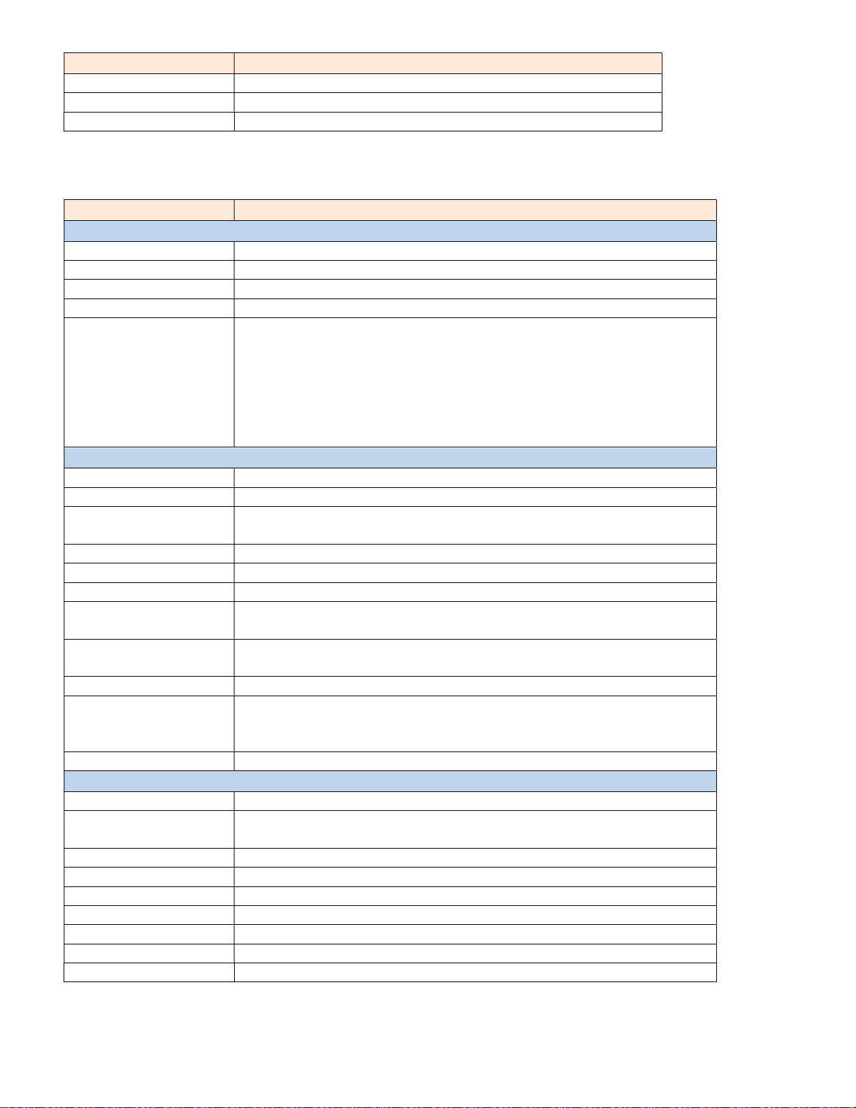
Data Entry Mode Button Operation
Button
Function
Setting
Options
(default settings in
Bold
) System
Menu
A/V Menu
Network Menu
Menu Go to previous field, back to Menu, or exit Menu
Up / Down Change selected data
Select Go to next field or save selected data and go back to Menu
On-Screen Text Menu Settings
Baud Rate 1200 | 2400 | 4800 | 9600 | 19.2K | 38.4K | 115.2K | 230.4K
Pnl Lockout None | Ch+Menu | Vol+Menu | CH+Vol+Menu |Power | Menu | All | Pwr+Menu
IR Receive On | Off
CEC Mode Disabled | Display On | Display OnOff
Firmware Press Select, then Up/Down to scroll through versions
ATSC-mini V1.03 – System Firmware
Volt In 11.8 – Power Supply voltage
HW Rev A0 – Hardware Version
HD Vers V1.03 – Demodulator/Decoder Firmware
Enter Boot Mode
Boot Ldr V1.00 – Bootloader Version
HD Output YPbPr | RGB
Output Resolution 480i | 480p |720p | 1080i |1080p | 2160p60 | Auto | 2160p30
Refresh Rate 59.94Hz | 60Hz
Applicable to 720p, 1080i only
Overscan % Sets the image overscan 0 – 9%
HDMI-DVI Auto | HDMI | DVI
HDMI Audio On | Off
AC3 Cmpr Mod Sets the compressor mode for the AC-3 downmix
Line | RF
Channel Box Enables the channel box on-screen graphic that appears during a channel change
Enable | Disable
Tune Mode Off-Air | CATV | Cable Auto | HRC | IRC
Scan Mode Sets the mode for the channel scan
Analog & Digital | Analog, Keep Digital | Analog, Del Digital
Digital, Keep Analog | Digital, Del Analog
Chan Scan Press Select to initiate channel scan
IP Address 192.168.1.231
IP Mode Select Static |DHCP
Gateway and Subnet Mask settings remain when toggled from DHCP to Static
Gateway 192.168.1.1 Set automatically when DHCP is selected
Subnet Mask 255.255.255.000
IP Port 23 Sets the port for Telnet communication
iCC-Net Device 00257 Sets the display device number for receiving iCC-Net control commands
MAC/SN 00:14:C8:1E:xx:xx
UDP Reply Off | On
Reset Network Password Press Select to clear the password for web page access
Page | 9 ATSC-mini HDTV Tuner Product Manual 072022
Page 10
HD2-RC IR Remote
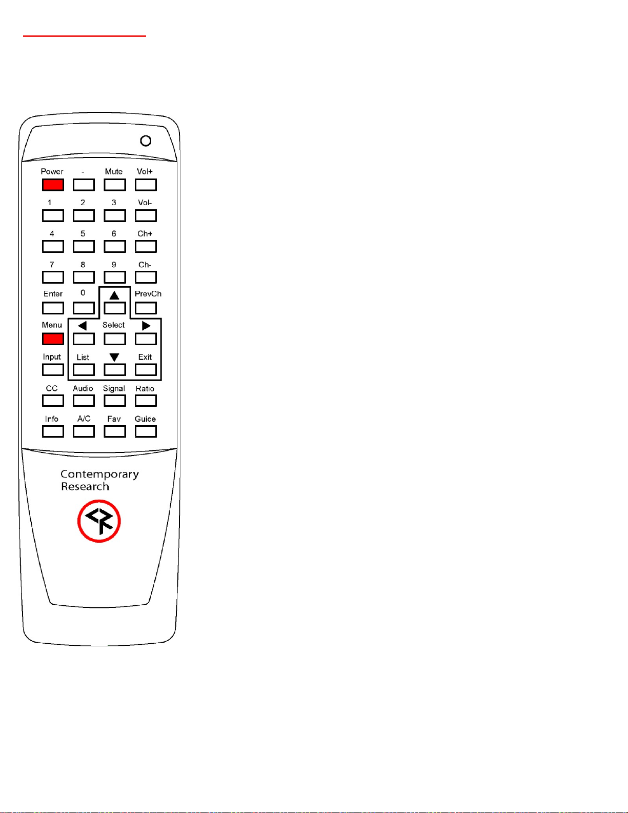
The optional HD2-RC IR Remote (5024-004) may be used to setup the ATSC-mini and for daily operation. The ATSC-mini is equipped with a
front panel IR sensor and a rear panel IR input jack for connection to an optional IR-RXD (5034-001) or compatible remote IR receiver. Each of
the functions on the remote have equivalent commands in RS-232 and wired IR formats.
Power
Press to toggle on and off.
Volume Control
Use the Vol+, Vol- and Mute buttons to control volume.
Channel Selection
Two-part major/minor channel numbers are separated by a – (dash). Example 21-3
One-part channels are accessed by entering the channel numbert digital channels are
Ch+, Ch- and PrevCh can be used to access and recall channels
Menu Operation
Press Menu to access the on-screen menus.
Use the directional arrows, Select and Exit to navigate the on-screen menus.
Exit closes the on-screen menu
Menu reverts to the previous menu or closes the on-screen menu from the Main
Menu
Enter selects the menu choice
Special Functions
CC steps through available closed-captioning options
Audio steps through main and SAP audio options
Signal launches up on-screen signal strength meter (digital channels only)
Ratio steps through aspect ratio options.
Input steps through the display inputs set with ER command
Info launches on-screen information banner.
A/C toggles air or cable tuning
Fav displays list of favorite channels
Guide launches on-screen guide, select a program and press Info to display program
information
Some features of the special function commands may only be available if supported
in the received channel.
Hold the Select button and press “9” to set the IR frequency at 57 KHz. Hold the
Select button and press “4” to set the IR to the normal 38 KHz frequency.
Page | 10 ATSC-mini HDTV Tuner Product Manual 072022
Page 11
On-Screen Graphical AV Menus
Main Menu
Channel Menus
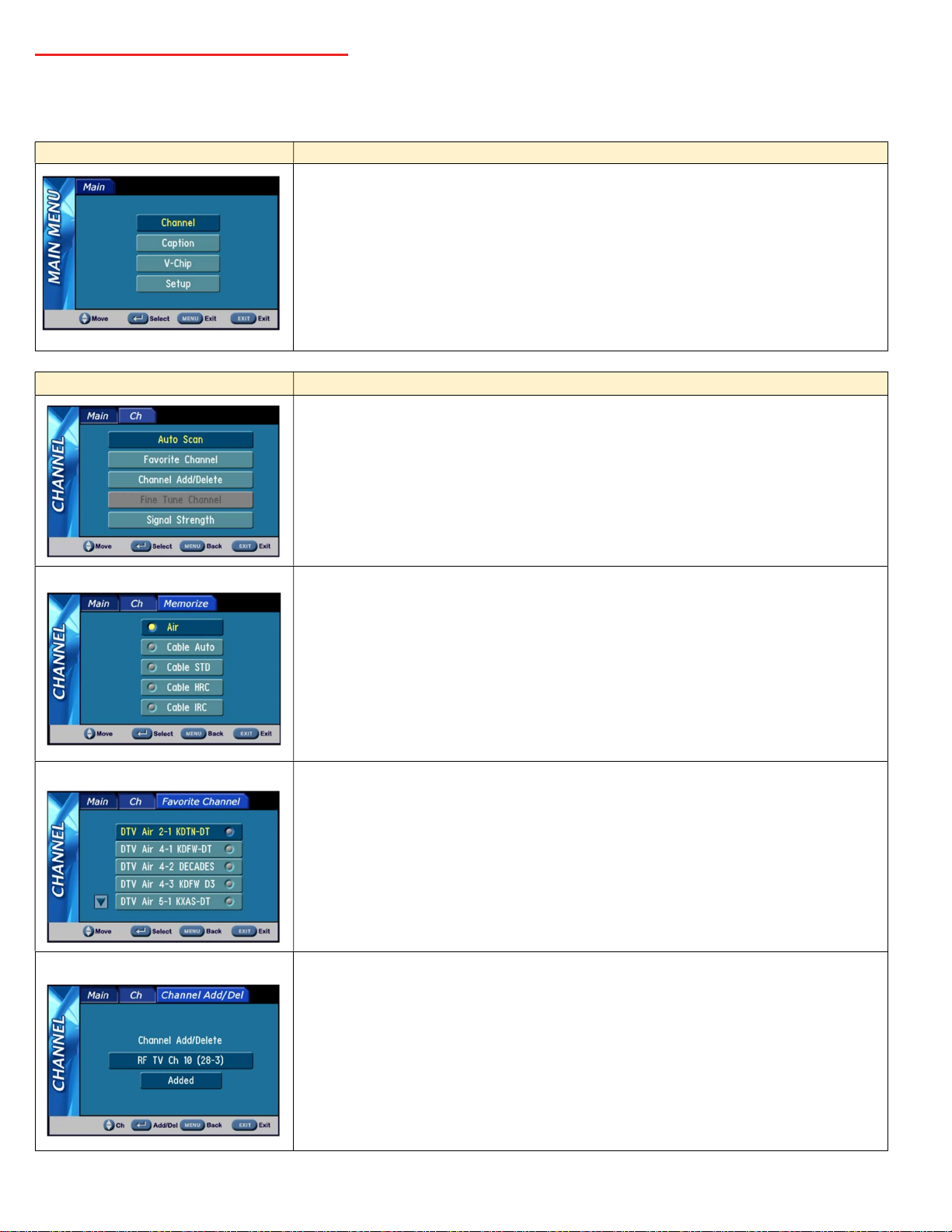
On-screen Graphical AV Menu may be accessed by Menu button on the front panel, Control web page, or optional HD2-RC handheld
infrared remote.
Select Sub Menus
Down or Up highlights option
Select + Down moves left (front panel control only)
Select + Up moves right (front panel control only)
Select chooses Option
Menu steps back or exits menu
Sub menu for Channels offers options for:
Channel Auto Scan
Favorite Channels
Channel Add/Delete
Fine Tune Channel (Analog Channels Only)
Signal Strength (Digital Channels Only)
Auto Scan
Favorite Channels
Channel Add/Delete
Press Up/Down to highlight scan mode
Press Select to initiate channel scan
Analog channels will be scanned first, then digital channels. The channel list will be
populated as channels are found. Press Select during scan to skip analog channels.
Menu page for creating a list of favorite channels. Channels will be advanced by FAV
button or favorite channel commend
Press Up/Down to highlight channel
Press Select to Add//Delete from list
Channels may be added or deleted from the list of memorized channels. Channel
Up/Down will step through the physical RF channels displaying the virtual channel
numbers of received channels. Select will add or delete the selected channel. Note that in
the case of multiple sub channels on a physical channel, only the displayed sub channel will
be added or deleted.
Page | 11 ATSC-mini HDTV Tuner Product Manual 072022
Page 12
Signal Strength
Caption Menu
s
Version Info
V-Chip Menu
US Rating Setting
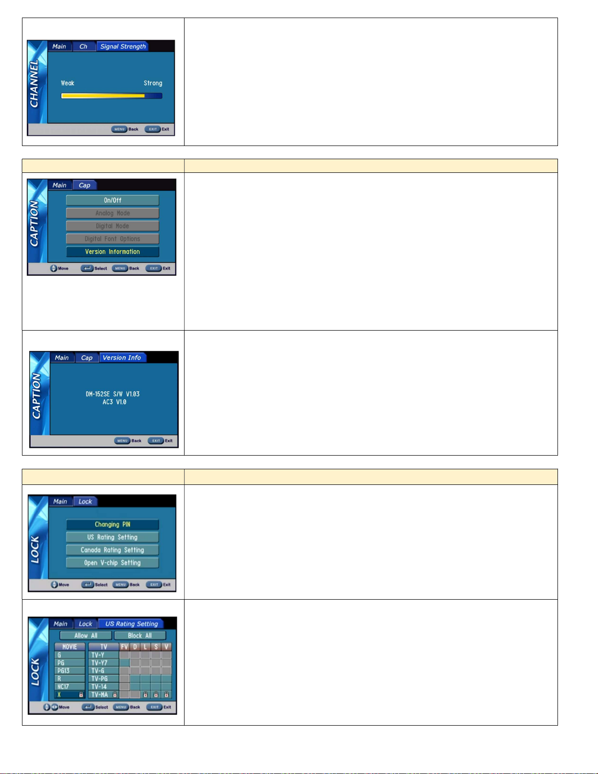
This page can also be displayed from the Signal remote command. The graphic shows the
current signal strength and changes in real time. The strength of a channel may be
monitored as the antenna positioning is adjusted for optimum reception.
This menu accesses captioning features:
On/Off — turns captions on/off
Note: Other options are not available if captions are off.
Analog Mode — CC 1-4 and Text 1-4
Digital Mode — Service 1-6
Digital Font Options
o Size — Standard (15 pixels), Large (21 pixels), or Small (11 pixels)
o Style — 1-6
o Color — 8 shades of background, foreground, and edge colors
o Opacity — foreground and background
o Edge — 6 style options
Displays the hardware type of the decoder/demodulator board and HD firmware version.
Also displays the AC-3 firmware version.
This menu manages access to programming based on US and Canadian ratings standards.
A PIN number is required to access any of the sub menus. The default PIN number for
access is 0000 (four zeros).
Changing PIN accesses menu to create new PIN
Open V-chip Setting clears all rating settings
Use navigation and Select buttons to select/deselect options. The padlock symbol
indicates channels with the selected rating will be blocked and the PIN will be required for
viewing.
Page | 12 ATSC-mini HDTV Tuner Product Manual 072022
Page 13
Canada Rating Setting
Setup Menus
Screen Format
Time
Time Zone
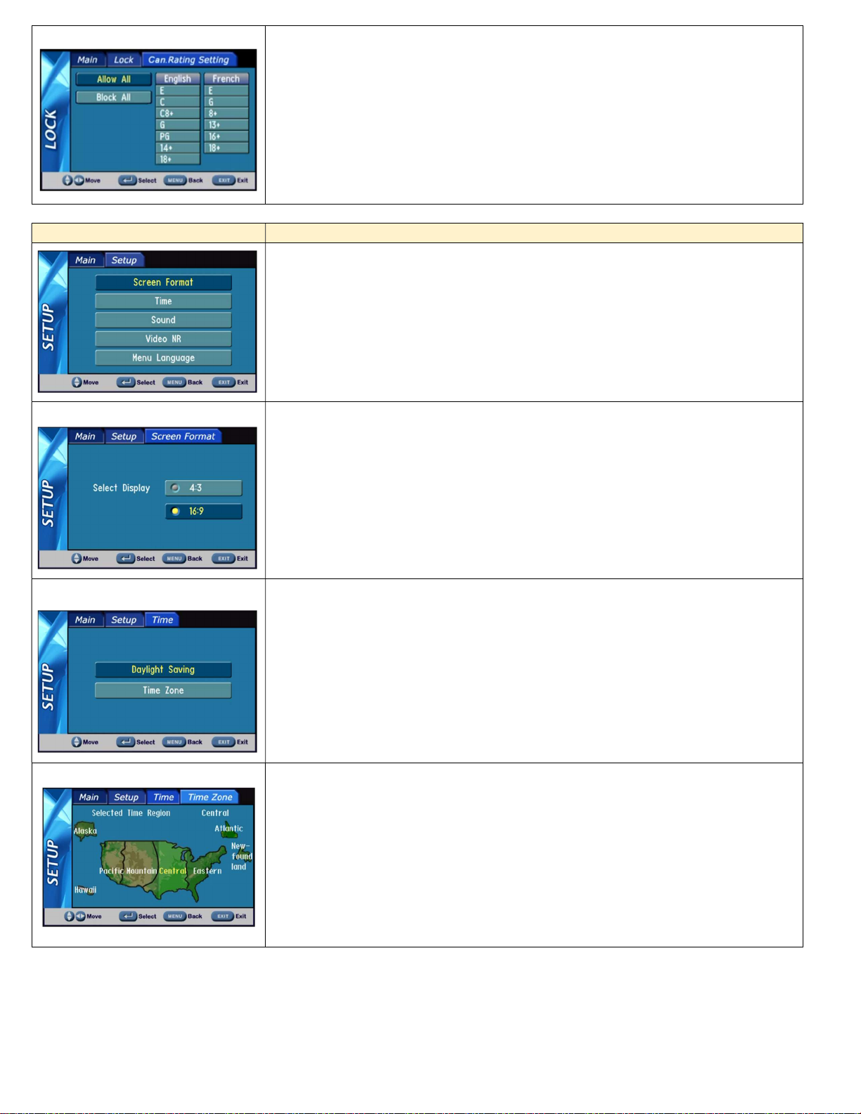
Sub menu equivalent to US Rating setting for Canadian applications.
This series of menus select the options for tuner operation:
Screen Format —16:9 or 4:3
Time
Sound Settings
Video Noise Reduction — Available only for analog channels
Menu Language
Select the appropriate aspect ratio for the connected display.
Sub menus for time settings.
Time data is extracted from the System Time Table in the digital channel’s transport stream
if available.
When Daylight Saving is enabled, the tuner will adjust the time as needed if the daylight
savings flag is enabled in the System Time Table.
Move cursor left and right to select the time zone. Select stores the highlighted zone.
Front panel navigation
Select + Down to move left
Select + Up to move right
Page | 13 ATSC-mini HDTV Tuner Product Manual 072022
Page 14
Sound
Menu Language
Info Banner
Guide
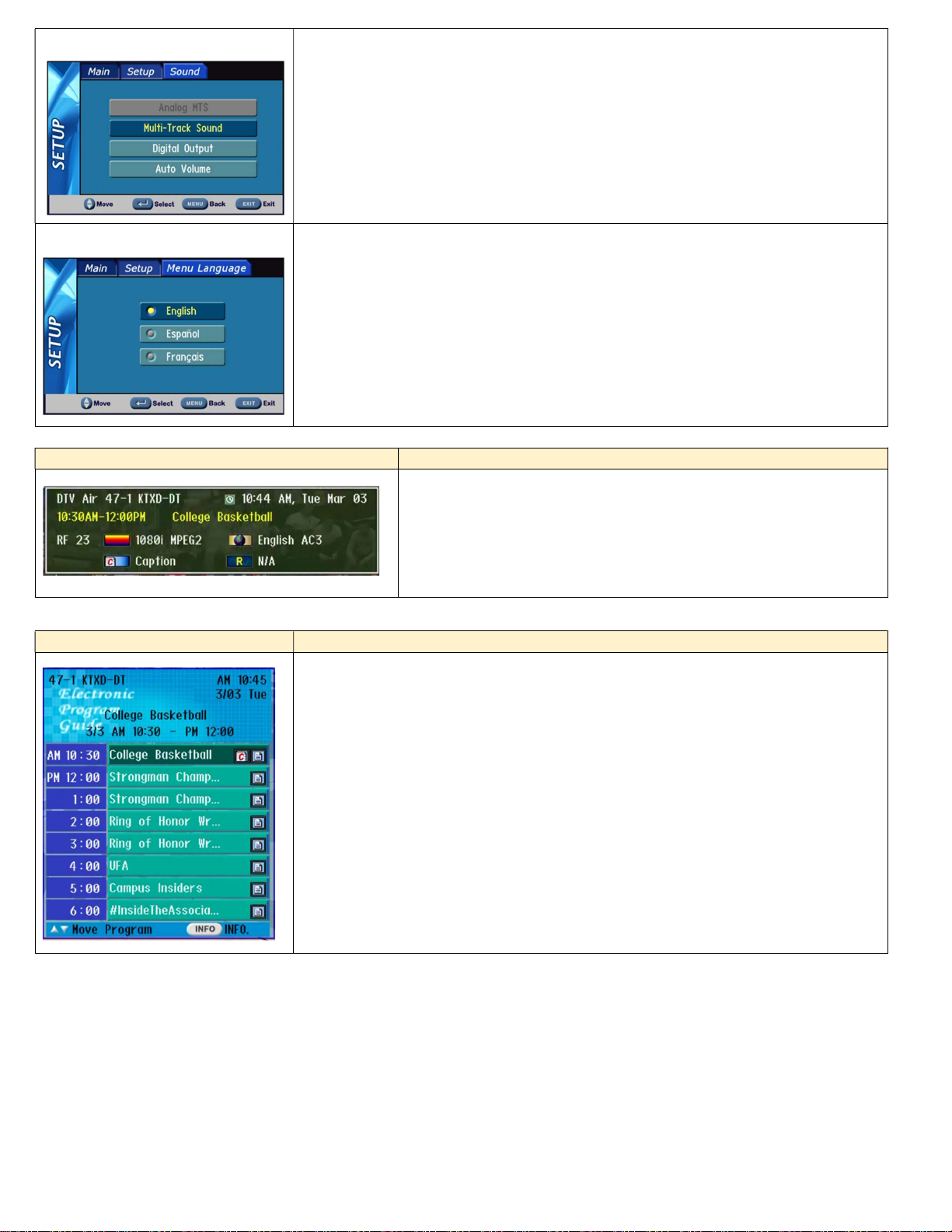
Select from a variety of options:
Analog MTS — Mono, Stereo, SAP
Multi-Track Sound — English, French, Spanish
Digital Out — AC-3, PCM, or variable-level PCM.
Auto Volume — On or Off
Select the language for the on-screen A/V graphical menus.
On-screen Info banner may be accessed by the following:
Info button press on IR remote or control web page
Hold Select button on the front panel
RS-232 command
On-screen Guide with a list of upcoming programs may be accessed by the following:
Guide button press on IR remote
RS-232 command
Use Up/Down to highlight a program. Info button press or equivalent will bring up a
program description. Guide list is limited to twelve hours of programming.
Page | 14 ATSC-mini HDTV Tuner Product Manual 072022
Page 15
Web Pages
The ATSC-mini has on-board web pages for control, monitoring, and configuration. The web pages may be accessed using a web browser by
entering the unit’s IP address in the browser’s address field. The web pages may also be accessed through CR Toolbox. Double-clicking on a
tuner in the equipment list will launch the default web browser and navigate to the tuner.
Beginning with Application firmware v1.10, access to the on-board web pages will be password protected by default.
Three modes of protection are available.
Password will be required to access all web pages (default).
Free access to the Control web page, but password will be required to access all other web pages.
Free access to all web pages.
For increased security when password protection of the web pages is desired, it is recommended to lock out the Menu button on the front
panel of the tuner.
Default Password
The default password is based on the last six digits of the unit’s MAC address. The MAC address may be found on the SN/MAC sticker on
the rear of the tuner. The MAC address information is also available in the on-screen text Network Setup menu. To access the on-screen
text Network Setup menu, follow these steps below.
Hold the Menu button to display the on-screen text menu.
Press Up or Down to step through the menu options until Network Setup is displayed, then press Select.
Press Up or Down to step through the menu until MAC/SN is displayed.
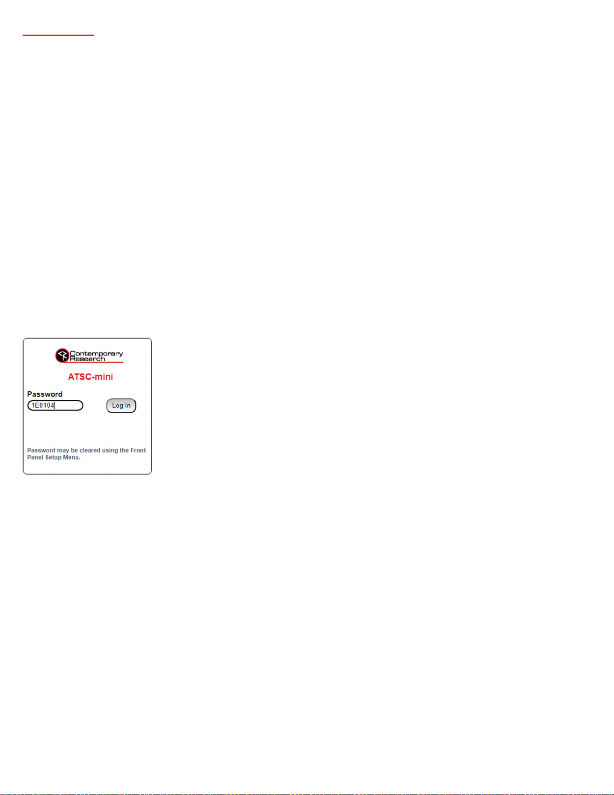
When the web page is first accessed, the browser will be directed to the login page. Enter the last six
digits of the MAC address in the password field, then click the Log In button. The characters should be
entered with no punctuation or spaces. Letters should be entered as upper case. i.e.: 1E0104
Update Password
The password can be updated in the System web page. Enter the new password in the New Password field and click the Change button.
The password may consist of up to 20 characters. The characters can be any combination of numbers, upper- and lower-case letters, and
special characters.
Page | 15 ATSC-mini HDTV Tuner Product Manual 072022
Page 16
Free Access to Control Web Page Only
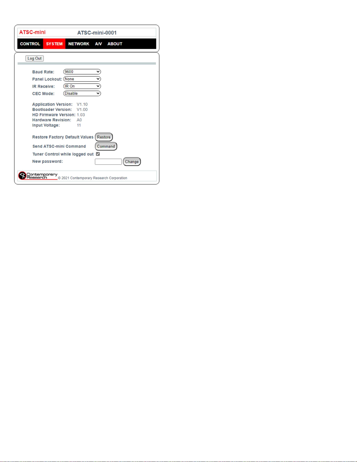
An option is available that will allow password free access to the Control
web page while maintaining password protected access to the web pages
related to setup and configuration. To enable this option, log in and
navigate to the System web page. Click the checkbox next to Tuner Control
while logged out near the bottom of the page.
If this option is enabled, a Tuner Control button will appear on the log-in
page. Clicking on the Tuner Control button will navigate to the Control web
page without entering a password. Log in will be required to navigate to
any other web page.
Free Access to All Web Pages
Clearing the password will allow password free access to all web pages.
The password may be cleared in the System web page. Clear the contents of the New Password field and click the Change button.
The password may also be cleared in the tuner’s on-screen text System Setup menu. Follow the steps below.
Hold the Menu button to display the on-screen text menu.
Press Up or Down to step through the menu options until Network Setup is displayed, then press Select.
Press Up or Down until Clear Network Password is displayed.
Press the Select button to clear the password.
Reset Default Password
The password will be reset to the default by reloading the factory default settings. This may be performed from the System web page. Click
on the Restore button next to Restore Factory Default Values. It is recommended to perform a hard power cycle after the default settings
are restored.
If access to the web page is not available, the factory default settings may be restored from the on-screen text System Setup menu.
Follow the steps below to reload the factory default settings.
Hold the Menu button to display the on-screen text menu.
Press Up or Down to step through the menu options until System Setup is displayed, then press Select.
Press Up or Down until Firmware is displayed, then press Select.
Press Up or Down until ATSC-mini V1.xx is displayed in the lower row of text.
Simultaneously press Power and Up.
Alternately, the factory default settings may be reloaded by RS-232 command. Refer to the section starting on page 19 for additional
information.
Page | 16 ATSC-mini HDTV Tuner Product Manual 072022
Page 17
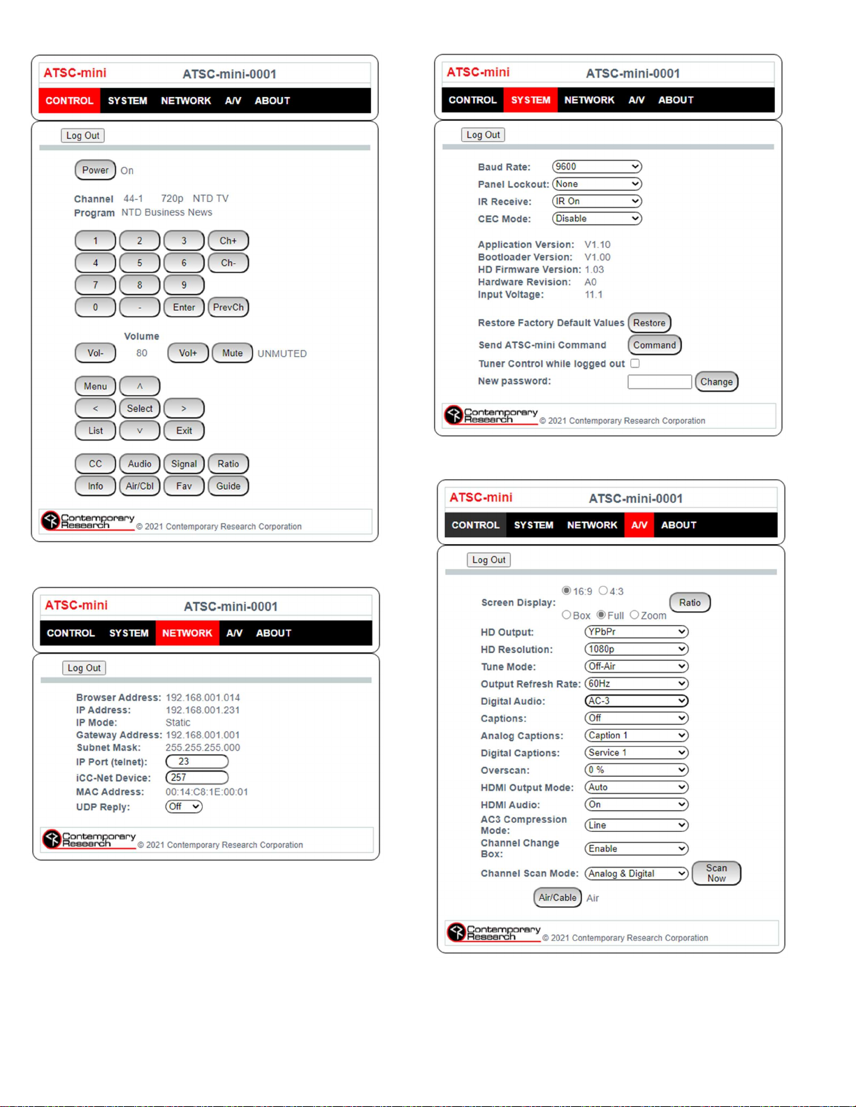
Control Web Page System Web Page
A/V Web Page
Network Web Page
Page | 17 ATSC-mini HDTV Tuner Product Manual 072022
Page 18
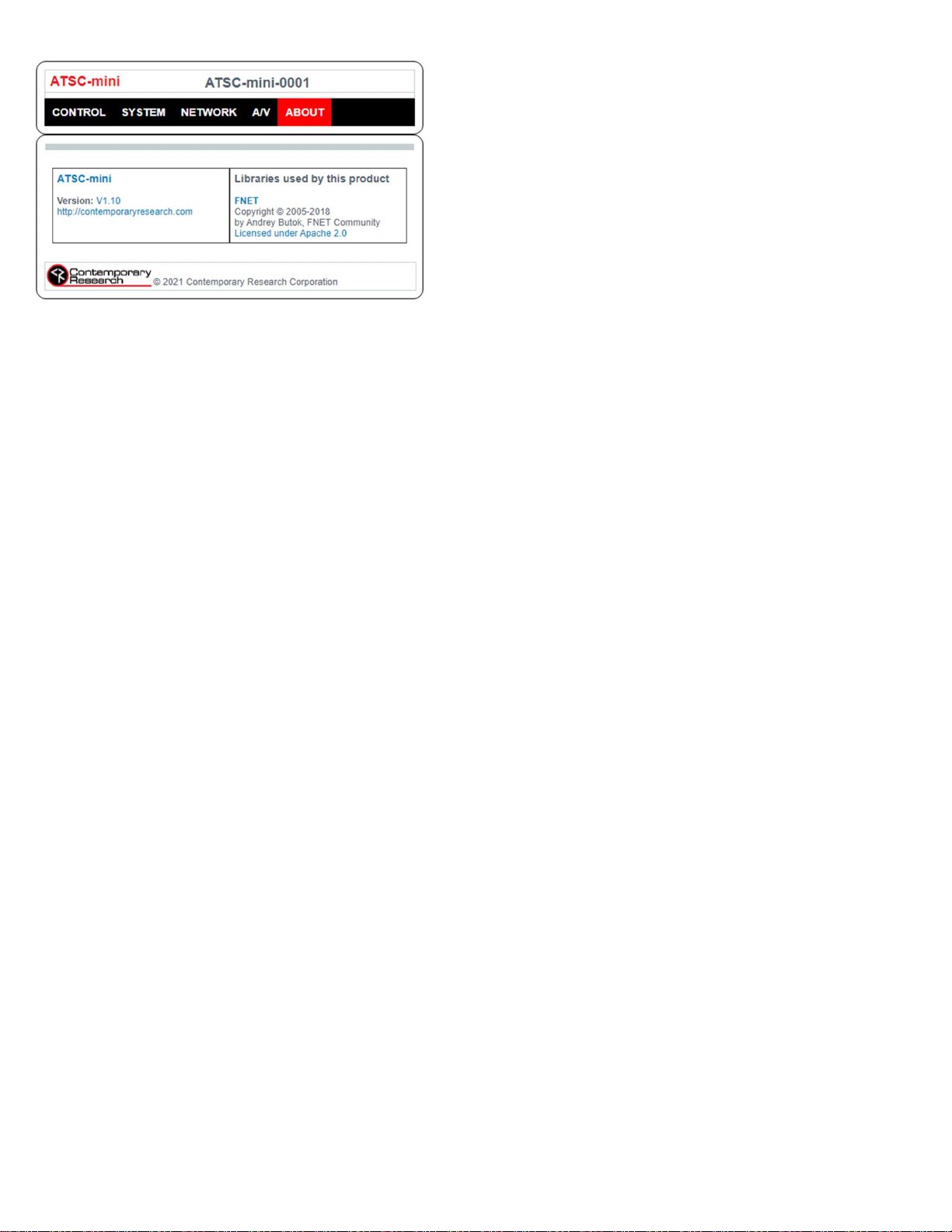
About Web Page
Page | 18 ATSC-mini HDTV Tuner Product Manual 072022
Page 19

RS-232/Telnet/UDP Control Protocol
The ATSC-mini full duplex RS-232/Telnet protocol enables a system programmer to control all tuner functions, configure the tuner, and
monitor tuner status. All commands are sent as ASCII strings. No delays between characters or commands are required, as data is interrupt
driven and buffered.
Communications parameters are 1200 to 230,400 baud, 8 data bits, no parity, and 1 stop bit. Factory default is 9600 baud. All settings are
saved to NVRAM in the ATSC-mini tuner. The RS-232 port will accept non-standard control such as voltage that swings from 0 to +5 VDC,
commonly found when IR ports are used to send RS-232 commands.
The same commands can be sent over IP Telnet (up to two sessions) and via UDP to the tuner’s IP address to port 31931 (fixed). UDP
responses are disabled by default. Responses will be sent to port 31932 at the directed broadcast IP address of the tuner’s subnet. UDP
responses may be enabled in the on-screen text menu, web page Network Settings menu, or RS-232 command. See our Support Blog
Testing 232-ATSC Series UDP Control at https://contemporaryresearch.com/testing-232-atsc-udp-control/ to learn more about UDP control.
General Protocol Specifications
Characters in command strings to the ATSC-mini are common ASCII keyboard characters. Command strings sent to the ATSC-mini begin with
the ASCII > (greater than symbol) as an ‘Attention’ character and end with carriage return - ASCII CR, Hex $0D, or keyboard Enter - as an
‘End-of-command’ character.
For commands that require a parameter value, the = (equals symbol) shown in the examples is optional.
Responses from the ATSC-mini begin with the ASCII < (less than symbol) as an ‘Attention’ character and end with a carriage return followed
by a line feed - ASCII LF or Hex $0A as an ‘End-of-command’ character.
A carriage return is required at the end of each command and is assumed in all examples.
Command String Structure
[Attention] [Command] (Parameters) [Return]
Attention Single character (>) starts the string
Command A two-character command
Parameters Added attributes to some commands
Return A carriage return ends the command string. ASCII CR, Hex $0D, or keyboard ‘Enter’ may be used in programming. For
simplicity, the programming examples in the manual will not show the ‘CR’.
Command and Status Response
Commands can be sent back-to-back at any time without any delay. To allow for rapid, multiple commands, status responses are
intentionally delayed by about 125 mS, sending the most recent status in response to control commands or user actions.
String Example
The example below is a command for a channel change to 6-2 followed by the response string.
>TC=6-2
<1TU006Uxx1002x0
The status of a setting may be queried by omitting the = (equals symbol) and the parameter value. The following command queries the 63
step volume level.
>VL
<VL=62
Page | 19 ATSC-mini HDTV Tuner Product Manual 072022
Page 20
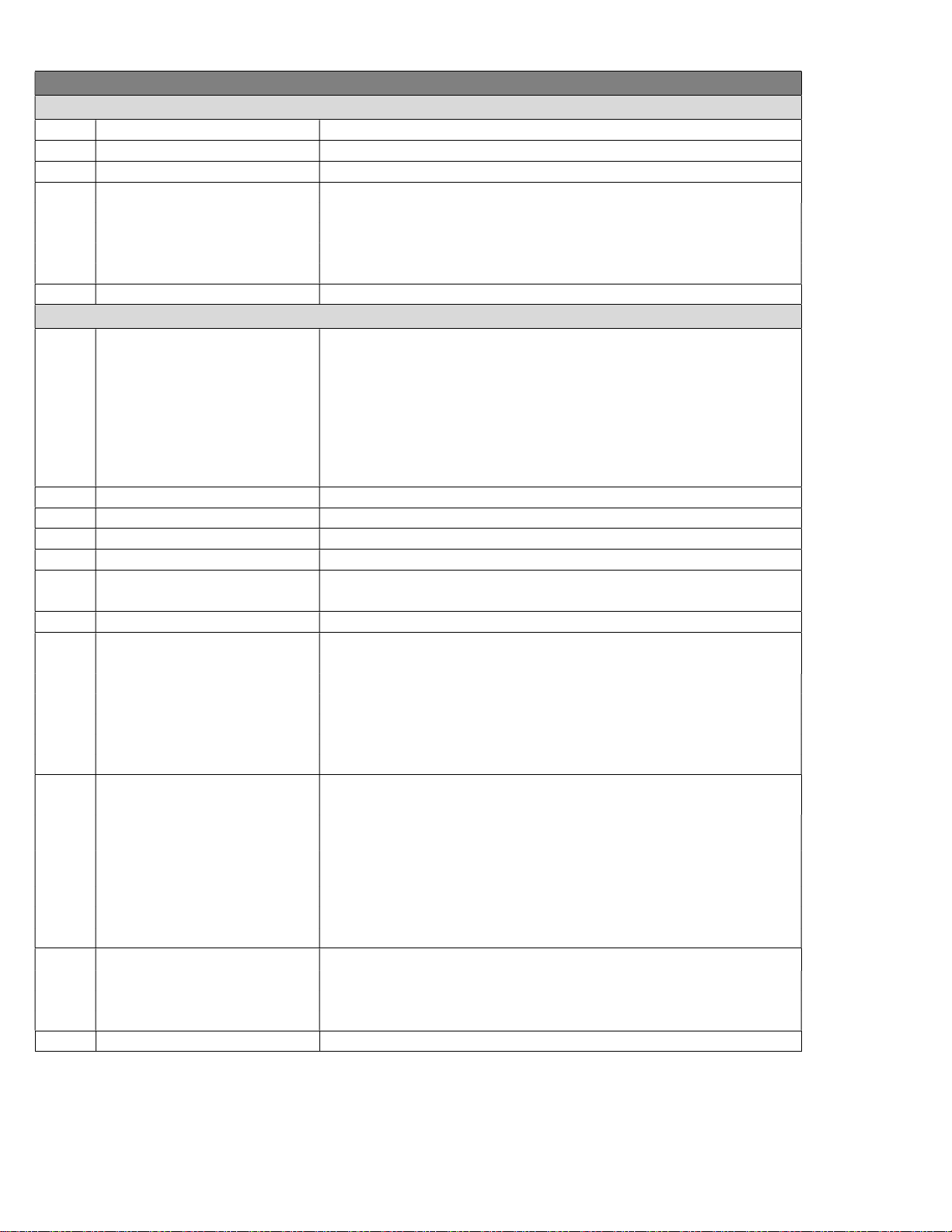
Control Commands
Code Function Operation
Front Panel
P1 Power On Brings unit out of standby
P0 Power Off Places unit in standby, mutes audio and video
PT Power Toggle Toggles standby mode
S4= Set Front Panel Lockout Mode 0=None 4=Power
1=Ch+Menu 6=Menu
2=Vol+Menu 7=All
3=Ch+Vol+Menu
Q5= Set IR Receive Mode 0=IR receive disabled 1=IR receive enabled
TC= Select Channel Tunes analog and digital channels, leading zeros OK, up to 4 characters for
Press Menu and Up key to unlock temporarily
Tuning
analog or one-part digital channel, 3 characters each for digital two-part major
and minor channels. For two-part channel commands, the major and minor
channel numbers may be separated by a colon or dash.
Examples:
>TC=28:1, >TC=28-1 Selects digital channel 28-1
>TC=32 Selects digital channel 32, analog channel 32 if no digital
>TC=32-0 Selects analog channel 32
TU Tune channel up Selects next higher channel in channel list
TD Tune channel down Selects next lower channel in channel list
TP Tune previous channel Selects previously viewed channel
NC Channel Name status Returns channel name as entered in channel list, up to 7 characters
NP Program Name status Returns program name, up to 30 characters, 15 additional if non-ASCII
characters are present, such as ñ
T^ Start Channel Scan Initiates a new channel scan, scan operation set by D0 and S0
S0= Tuning Format Sets tuning format for channel scan initiated from T^ command or front panel
Setup Menu
0=CATV -Switches to Cable Mode, sets standard channel spacing
1=Off-Air -Switches to Air Mode
2=IRC -Switches to Cable Mode, sets IRC channel spacing
3=HRC -Swichtes to Cable Mode, sets HRC channel spacing
4=Cable Auto -Switches to Cable Mode, auto detects channel spacing
D0= Analog/Digital scan mode Sets channel type for channel scan initiated from T^ command or front panel
Setup Menu
0=All -Scan for analog and digital channels, delete existing analog and digital
channels (default)
1=Digital -Scan for digital channels only, delete existing analog channels
2=Digital -Scan for digital channels only, keep existing analog channels
3=Analog -Scan for analog channels, delete existing digital channels
4=Analog -Scan for analog channels, keep existing digital channels
XA= Channel add XA=<major>,<minor>,<physical> Adds channel to list
Examples:
>XA=38,1,0 adds 38-1, physical channel 0 will be the same as major
>XA=8,0,13 adds virtual channel 8, found on physical channel 13
XD= Channel delete XD=<major>,<minor> Removes channel from list
Page | 20 ATSC-mini HDTV Tuner Product Manual 072022
Page 21
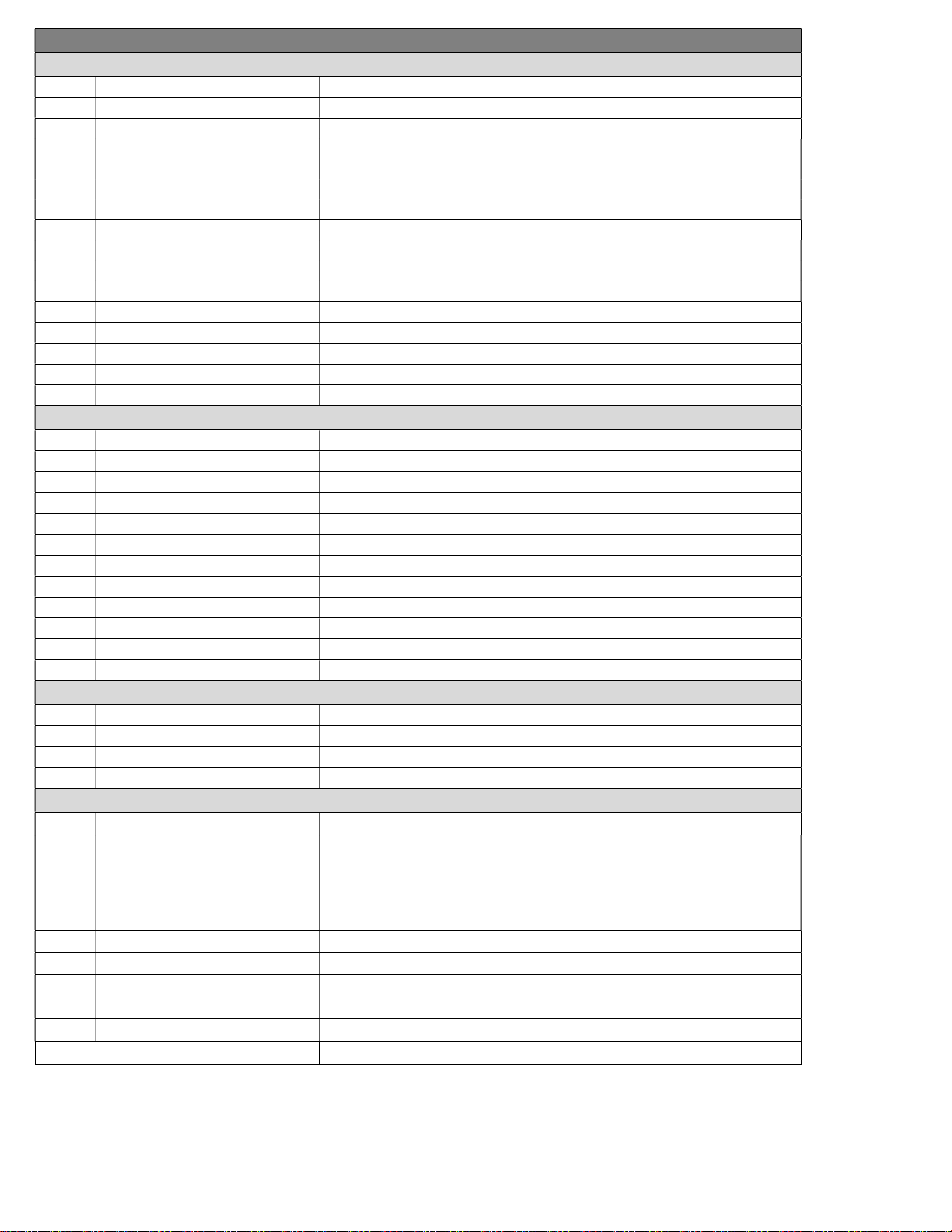
Code Function Operation
Video Output
D4= Overscan Selects Overscan percentage 0-9
Q0= Display Closed Captions 0=Captions off 1=Captions on
Q1= Analog Caption Service Selects analog caption service 1-8
1=Caption 1 5=Text 1
2=Caption 2 6=Text 2
3=Caption 3 7=Text 3
4=Caption 4 8=Text 4
Q7= Digital Caption Service Selects digital caption service 1-6
1=Service 1 4=Service 4
2=Service 2 5=Service 5
3=Service 3 6=Service 6
R6 Refresh Rate Sets to 59.94 Hz
RM Refresh Rate Sets to 60 Hz
KK=149 Output RGB Sets colorspace to RGB
KK=151 Output YPbPr Sets colorspace to Component
HD= HDMI/DVI mode 0=Auto 1=HDMI 2=DVI
Audio Output
VU Ramp volume up Starts volume ramping up
VD Ramp volume down Starts volume ramping down
VV Stop volume ramp Stops volume ramping
VH= Sets volume level 0-100 Volume level, scaled in 100 steps
VL= Sets volume level 0-63 Volume level, scaled in 63 steps (compatibility mode)
VM Volume Mute Enabled Mutes all audio outputs
VX Volume Mute Disabled Restores audio to previous level
VT Toggle Volume Mute Toggle mute mode
KK=158 AC-3 Sets the digital audio outputs to AC-3
KK=159 PCM Sets the digital audio outputs to PCM fixed
KK=160 PCM Variable Sets the digital audio outputs to PCM Variable
HA= HDMI Audio Mute 0=Audio mute disabled 1=Audio mute enabled
Status Request
ST Request T Mode status Returns T Channel/Source status string
SV Request V mode status Returns V Audio status string
SS Request S Mode status Returns S Front Panel status string
SQ Request Q Mode status Returns Q Mode status string
Network Setup
IP= Sets IP Address IP=xxx.xxx.xxx.xxx Defines IP address, then sends status
>IP returns the current MAC address, current IP address, subnet mask, and
gateway. Response example : $MAC=0014C81A001B
IP=192.168.001.231S IG=192.168.001.001 IM=255.255.255.000 IY=1.
S or D at end of IP signifies DHCP or Static address. 000.000.000.000 indicates
DHCP, but no DHCP server detected.
IM= Subnet Mask >IM=xxx.xxx.xxx.xxx. Defines subnet mask
IG= Default Gateway >IG=xxx.xxx.xxx.xxx. Defines default gateway
IY= IP Mode 1=Static 2=DHCP
IX= Telnet Port >IX=xxxxx Defines Telnet port
UO UDP Reply Enables reply strings to UDP port 31932
UF UDP Reply Disables reply strings to UDP port 31932 (default)
Page | 21 ATSC-mini HDTV Tuner Product Manual 072022
Page 22
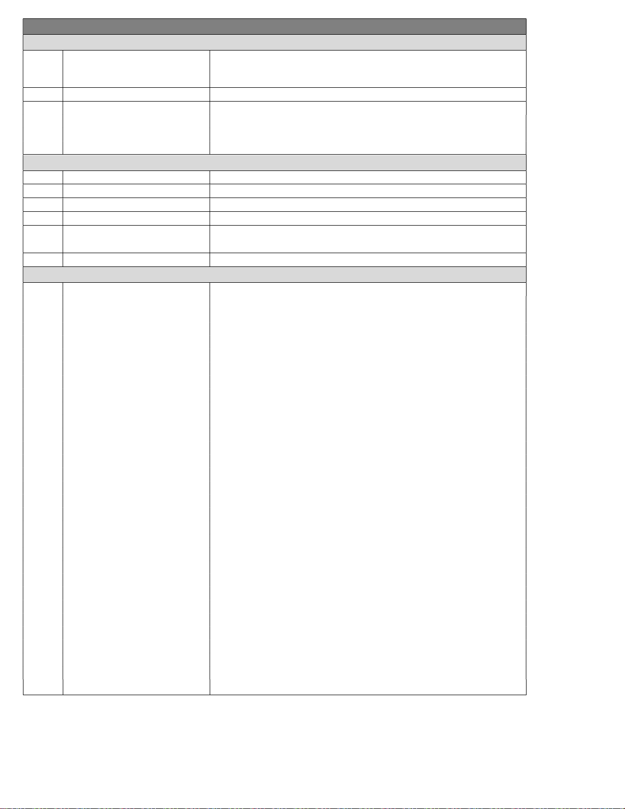
Code Function Operation
Serial Communication
EN Echo On Echo On
This command is not available for Telnet. Enable local echo in the terminal
program.
EF Echo Off Echo Off
R5 Baud Rate 0=1200 4=19.2K
1=2400 5=38.4K
2=4800 6=115.2K
3=9600 (Default) 7=230.4K
Miscellaneous Commands
HE Help Returns a list of serial commands
NW= Set Name Sets the ATSC-mini name. Limited to 20 characters
NM Get Name Returns the ATSC-mini name
ID ID Returns the product model and application firmware version
Z! Reload factory default settings Reconfigures unit for all factory default settings.
IP address will not revert to default until after a Z] command or power cycle.
Z] Reboot Emulates a reboot from a hard power cycle
HD2-RC IR Remote Emulation
KK= Emulate HD2-IR Button Presses 9=Power Toggle 105=Menu
10=0 106=Right
11=1 107=Left
12=2 108=Up
13=3 109=Down
14=4 110=Enter/Select
15=5 111=Exit
16=6 115=CC
17=7 141=Output Resolution 1080i
18=8 142=Output Resolution 720p
19=9 143=Output Resolution 480p
21=Enter/Select 144=Output Resolution 480i
22=Channel Up 145=Output Resolution 1080p
23=Channel Down 146=Output Resolution 2160p/60
24=Volume Up 147=Output Resolution Auto
25=Volume Down 148=Output Resolution 2160p/30
26=Mute Toggle 149=Output RGB
27=Power On 151=Output YPbPr
28=Power Off 153=Air
29=Menu 154=Cable
63=Guide 155=16:9 Ratio Pillar Box
81=Signal 4:3 Ratio Letterbox
82=Ratio 156=16:9 Ratio Full Wide
85=Audio 4:3 Ratio Full
88=Favorite 157=16:9 Ratio V Zoom
95=List 4:3 Ratio H Zoom
96=Add/Delete Channel 158=AC=3
98=Air/Cable 159=PCM
99=Dash 160=PCM Variable
100=Info 161=Display 16:9
101=Previous Channel 162=Display 4:3
Page | 22 ATSC-mini HDTV Tuner Product Manual 072022
Page 23

Response Strings
Typical: [Attention] [Unit#] [data ...data] [cr] [lf]
ATSC-mini status response strings contain ASCII characters similar to those used for the same functions in command strings. An ASCII
‘carriage return’ and ‘line feed’ follow each response string. Functions shown as N/A are not applicable or available in the ATSC-mini.
Characters will appear in status strings as lowercase ‘x’.
Channel/Source Status Response String (T):
Start Unit CMD Power Major
Channel
Fixed U=On
M=Off
< 1 T U 032 U 0 C 0 002 x 0
The ATSC-mini channel status is split into Major Channel and Minor Channel sections. The Minor Channel will always be 000 for analog
channels. The Minor Channel status will display “F00” if the Major channel is a special “one-part” digital channel. Also, as one-part channels
can go higher than 999, the Minor status will indicate how many thousands (up to 63) should be added to the Major number. Example:
Channel 1032 would return 032 for the Major Channel and F01 for the Minor Channel. Two-part channels are limited to 999-999.
Audio Status Response String (V):
Start Unit CMD Power Volume 1 Volume Mute Stereo Volume 2
Fixed U=On
< 1 V U 63 U x 100
Volume 1 emulates legacy 232-series volume level for compatibility with existing applications.
Volume 2 shows actual ATSC-mini level, from 0-100. Audio status will be sent automatically following a volume toggle command from front
panel control, IR remote, or RS-232- command.
Front Panel Mode Status Response String (S):
3 digits Unmuted 0=RF
0-63
M=Off
Emulated level
2 digits
Video
Mute
Input RF Received
U=Unmuted
M=Mute
A=Air
C=Cable
0=1080i
1=720p
2=480p
3=480i
4=1080p
N=No Sig
N/A 0-100
Resolution
Actual level
3 digits
Minor
Channel
3 digits 0=None
NA Function
Start Unit CMD Audio Tune
Mode
Fixed N/A 0=Cable
1=Air
2=IRC
3=HRC
4=Auto
< 1 S x x 0 08 4 2 0 0 xxxx
Lockout Bass Treble Output Output
Resolution
0-9 Fixed
2 digits
Fixed 0=RGB
2=YPbPr
0=1080i
1=720p
2=480p
3=480i
4=1080p
5=2160p/60
7=2160p/30
Output
Setting
0=1080i
1=720p
2=480p
3=480i
4=1080p
5=2160p/60
6=Auto
7=2160p/30
NA
4 digits
Page | 23 ATSC-mini HDTV Tuner Product Manual 072022
Page 24

Q Mode Response String (Q):
Start Unit CMD Q0 Q1 Q2 Q3 Q4 Q5 Q6 Q7 Q8 NA
Fixed CC
0=Off
1=On
< 1 Q 1 1 3 0 2 9 0 1 1 xx
CC
Type
1-8
Video
Detect
(fixed)
AV
Detect
(fixed)
Label
(fixed)
IR
0=Off
9=Normal
1
digit
Digital
CC
0=Off
1=On
Digital
CC
Services
1-6
2
digits
Page | 24 ATSC-mini HDTV Tuner Product Manual 072022
Page 25
Firmware Update
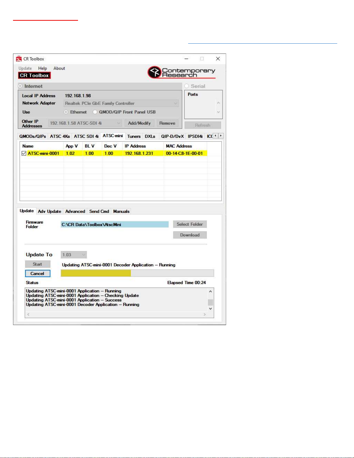
CR Toolbox software for Windows will be required for full firmware updates to the ATSC-mini as well as other supported Contemporary
Research products. CR Toolbox is available for download free of charge at https://www.contemporaryresearch.com/products/cr-toolbox/.
It is best for an internet connection be available when using CR Toolbox. Upon launch, CR Toolbox will scan the local subnet for supported
Contemporary Research devices. When a device tab is selected, CR Toolbox will compare the firmware available if any on the local hard
drive with the firmware available on the Contemporary Research cloud firmware database. If newer firmware is available for download,
the Download button will turn red.
Click on the ATSC-mini to view connected devices. If no devices are found, verify the appropriate network adaptor has been selected from
the drop-down menu and that the network adaptor and ATSC-mini devices are set for the same subnet.
Follow this procedure to perform a firmware update:
Click the checkbox for the ATSC-mini units to be updated
Select the desired version from the Update To drop down menu
Press Start to initiate the update
Status of the update will be displayed in the Status box.
When the process is complete, the status bar will turn green.
The status bar will turn red if any part of the firmware update fails
Page | 25 ATSC-mini HDTV Tuner Product Manual 072022
Page 26
ATSC-mini Specifications
Physical
Size (HWD): 8” [203 mm] wide (8.6” [218 mm] including wings) x 1.150” [29 mm] height x 3.6” [91 mm] deep
Weight: 0.877 lbs [398 g]
Enclosure: Aluminum with black powder coat paint
Mounting: Hook-and-loop fasteners or screw attachment
Front Panel
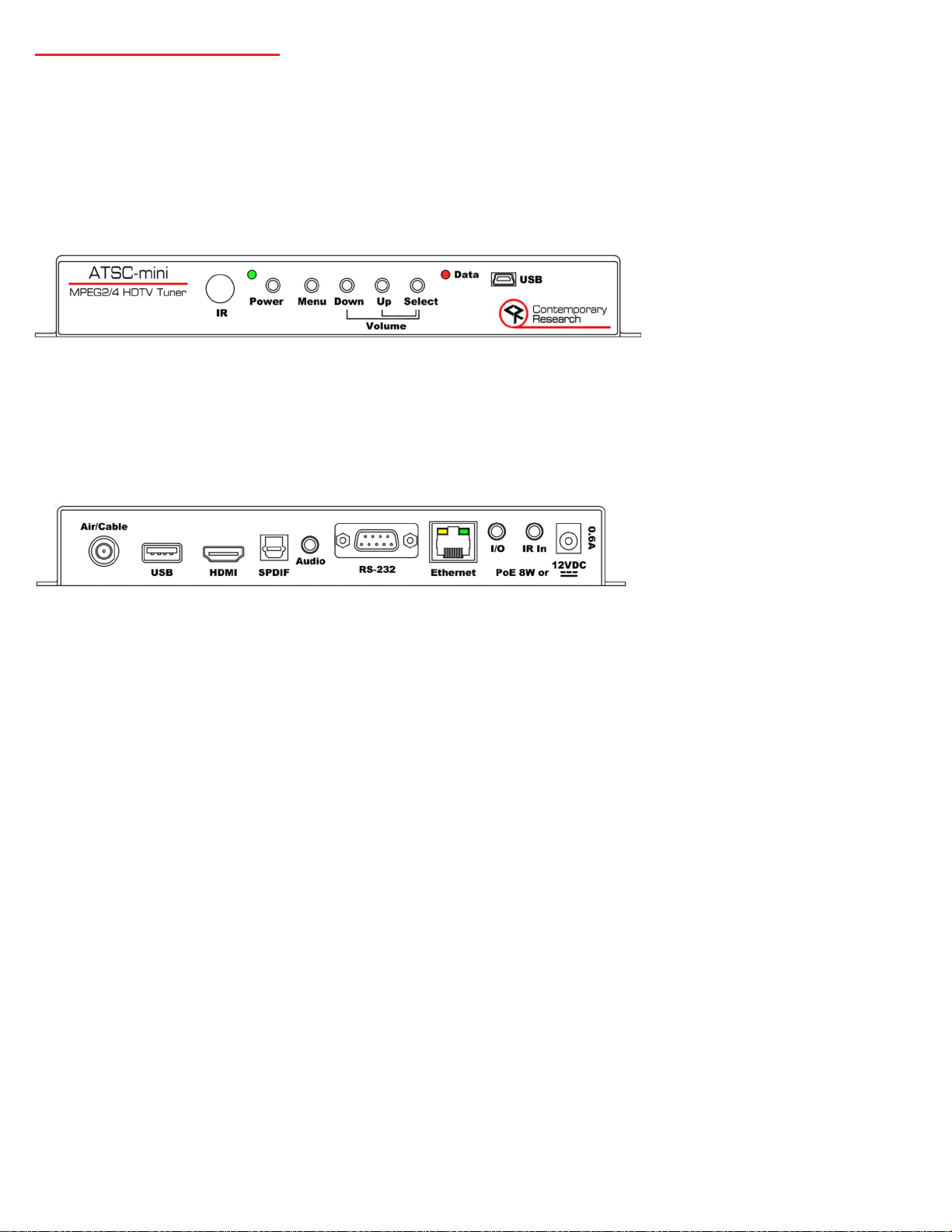
IR: IR Remote Sensor
Status: Red/green status LED
Control: Five button control
Data: Red/green RS-232 data activity indicator LED
USB: Mini-B virtual com port for future use
Back Panel
Air/Cable: “F” female, 75 ohm impedance, -10 to 25 dBmV typical
USB: USB-A port for demodulator/decoder firmware updates
HDMI: HDMI receptacle, Type A, Version 1.4b
Resolutions and Frame Rates:
480i — 29.97 Hz
480p – 60 Hz
720p — 59.94/60 Hz
1080i — 29.97/30 Hz
1080p — 60 Hz
2160p — 30/60 Hz
SPDIF: JIS F05 jack for optical S/PDIF digital audio output
Audio: 3.5mm TRS jack for analog stereo audio
RS-232: DB-9 male data link to control system or for display control, 1200 to 230K baud (9600 default)
Ethernet: RJ-45 10/100 for web page access, Telnet and UDP control, firmware updates, PoE
I/O: 3.5mm TRS jack for future use
IR In: 3.5 mm TRS jack for optional external IR receiver or wired IR
Tip= +5 VDC (50 mA max)
Ring= Input
Sleeve= Ground
12VDC: Power input 11.5 to 15 VDC, 12 VDC typical, 0.6 A max
2.1 mm coaxial jack (inside center conductor positive)
Page | 26 ATSC-mini HDTV Tuner Product Manual 072022
Page 27

Tuning
Frequency Range: 51.0027 to 864 MHz
TV System: ATSC 1.0, clear QAM, NTSC
Channels: Air 2-69 (8-VSB and NTSC) and CATV 2-135 (QAM-64, QAM-256, 8-VSB, and NTSC), Standard, IRC, HRC
V-Chip: Supports parental channel block based on US and Canadian ratings
Decoding
Video: MPEG-2 (480i, 480p, 720p, 1080i), H.264 (480i, 480p, 720p, 1080i, 1080p)
Audio: AC-3, MPEG-1 Layer 2, AAC
Captions
Analog: Decodes Line 21 captions
Digital: Decodes CEA-608 and CEA-708 captions, CEA-708 captions may be customized for font size and style
Includes
PS12-1.0 Power Supply (5401-001)
Options
HD2-RC IR Tuner Remote, 4AAA batteries (5024-004)
CC-COM-B RS-232 Null Modem Serial Cable DB-9 F to DB-9 F 6 ft. (5061-003)
IR-RXD External IR Receiver (5034-001)
Trademarks
HDMI, the HDMI logo, and High-Definition Multimedia Interface are trademarks or registered trademarks of HDMI Licensing, LLC
Manufactured under license from Dolby Laboratories, Dolby and the double-D symbol are trademarks of Dolby Laboratories
Page | 27 ATSC-mini HDTV Tuner Product Manual 072022
Page 28

Safety Instructions and Warranty
Read before operating equipment.
Cleaning - Unplug this product from the wall outlet before cleaning. Do not use liquid cleaners or aerosol cleaners. Use
a damp cloth for cleaning.
Power Sources - Use supplied or equivalent UL/CSA approved low voltage DC plug-in transformer.
Outdoor Antenna Grounding - If you connect an outside antenna or cable system to the product, be sure the antenna
or cable system is grounded so as to provide some protection against voltage surges and built-up static charges. Section
810 of the National Electrical Code, ANSI/NFPA No. 70, provides information with respect to proper grounding of the
mast and supporting structure, grounding of the lead-in wire to an antenna discharge unit, size of grounding
conductors, location of antenna discharge unit, connection to grounding electrodes, and requirements for the
grounding electrode.
Lightning - Avoid installation or reconfiguration of wiring during lightning activity.
Power Lines - Do not locate an outside antenna system near overhead power lines or other electric light or power circuits or
where it can fall into such power lines or circuits. When installing an outside antenna system, refrain from touching such power
lines or circuits, as contact with them might be fatal.
Overloading - Do not overload wall outlets and extension cords as this can result in a risk of fire or electric shock.
Object and Liquid Entry - Never push objects of any kind into this product through openings as they may touch
dangerous voltage points or short out parts, resulting in a fire or electric shock. Never spill liquid of any kind on the
product.
Servicing - Do not attempt to service this product yourself as opening or removing covers may expose you to dangerous
voltage or other hazards. Refer all servicing to qualified service personnel.
Damage Requiring Service - Unplug this product from the wall outlet and refer servicing to qualified service personnel
under the following conditions:
o When the power supply cord or plug is damaged.
o If liquid spills or objects fall into the product.
o If the product is exposed to rain or water.
o If the product does not operate normally by following the operating instructions. Adjust only those controls
that are covered by the operating instructions. An improper adjustment of other controls may result in damage
and will often require extensive work by a qualified technician to restore the product to its normal operation.
o If the video product is dropped or the cabinet is damaged.
o When the product exhibits a distinct change in performance, this indicates a need for service.
Heat – This product should be situated away from heat sources such as radiators, heat registers, stoves, or other
products (including amplifiers) that produce heat.
* Note to CATV system installer: This reminder is provided to call CATV system installer's attention to Article 820-40 of the
National Electrical Code (Section 54 of Canadian Electrical Code, Part I), that provides guidelines for proper grounding and, in
particular, specifies that the cable ground shall be connected to the grounding system of the building as close to the point of
cable entry as possible.
Page | 28 ATSC-mini HDTV Tuner Product Manual 072022
Page 29

Warranty: Three (3) year limited warranty on all parts and labor for Contemporary Research manufactured products.
Contemporary Research warrants its manufactured products against defects in materials and workmanship for a period of
three years from the day of purchase by authorized dealer. If Contemporary Research receives notice of such defects during the
warranty period; Contemporary Research, at its option, will repair or replace products that prove to be defective.
Exclusions: The above warranty shall not apply to defects resulting from improper or inadequate maintenance by the customer,
customers applied software or interfacing, unauthorized modifications or misuse, mishandling, operation outside the normal
environmental specifications for the product, use of the incorrect, modified or extended power supply, acts of God, weather, or
improper site operation and maintenance. Please note Contemporary Research SSV-DX Display Express PC product carries a sixmonth limited warranty.
Product Service: Contemporary Research will test, repair, or replace the product or products without charge if the unit is under
warranty. If the product is out of warranty, Contemporary Research will test, and then repair the product or products. The parts
and labor charge will be estimated by a technician and confirmed by the customer prior to repair. All components must be
returned for testing as a complete unit. Contemporary Research will not accept responsibility for shipment after it has left the
premises.
Technical Support: Contemporary Research technicians will determine and discuss with the customer the criteria for repair
and/or replacement. Contemporary Research Technical Support can be contacted through one of the following resources: email support at [email protected] or phone at: 972-931-2728
Return Material Authorization (RMA) Number: Before returning a product for repair or replacement, request an RMA from
Contemporary Research’s technical support. Provide tech support with a return phone number, e-mail address, shipping
address, product serial numbers and original purchase order number. Describe the reason for repairs or returns as well as the
date of purchase. See the General RMA Terms and Procedures section for more information. RMA’s are valid for 30 days and
will be issued to authorized Contemporary Research dealers only. End users must return products through authorized
Contemporary Research dealers. Include the assigned RMA number in all correspondence with Contemporary Research. Write
the assigned RMA number clearly on the shipping label of the box when returning the product. All products returned for credit
are subject to a restocking charge without exception.
Voided Warranty: The warranty does not apply if the original serial number has been removed or if the product has been
disassembled or damaged through misuse, accident, acts of God, weather, modifications, use of incorrect, modified or
extended power supply, or unauthorized repair.
Shipping and Handling: Contemporary Research will not pay for inbound shipping transportation or insurance charges or accept
any responsibility for laws and ordinances from inbound transit. Contemporary Research will pay for outbound shipping,
transportation, and insurance charges for all items under warranty, but will not assume responsibility for loss and/or damage
by the outbound freight carrier. If the return shipment appears damaged, retain the original boxes and packing material for
inspection by the carrier. Contact your carrier immediately.
Products not under Warranty: Payment arrangements are required before outbound shipment for all out of warranty products.
Page | 29 ATSC-mini HDTV Tuner Product Manual 072022
Page 30

General RMA Terms and Procedures: RMA’s are valid for 30 days and will be issued only to authorized active Contemporary
Research dealers and distributors.
End users must return products through authorized Contemporary Research dealers. End users may be eligible for a
RMA at the discretion of CR Technical Support.
Before a defective product can be authorized to send in for repair, it must first go through the troubleshooting process
with a member of the Contemporary Research Technical Support team.
Products authorized for repair must have a valid RMA (Return Material Authorization) number.
Contemporary Research Technical Support will approve the issue of an RMA number.
An RMA number is to be included in all correspondence with Contemporary Research.
The RMA number must appear clearly on the shipping label when the product is returned.
A packing slip must be included on the inside of the box with the RMA number listed and reason for RMA return.
Products received at Contemporary Research that do not have a valid RMA number clearly marked on the outside of
the shipping container may be refused and returned to sender.
Boxes showing external damage will be refused and sent back to the sender regardless of the clearly marked RMA
number and will remain the responsibility of the sender.
Advanced Replacement Policies:
For Contemporary Research manufactured products, advance replacement will be provided for “out-of-the-box”
failures up to thirty (30) days after the initial shipment of products.
Shipments of equipment that are refused upon attempted delivery, for any reason, are subject to restocking charges.
Page | 30 ATSC-mini HDTV Tuner Product Manual 072022
 Loading...