

Page 1

USB22 Series
ARCNET® Network Interface Modules with USB Interface
INSTALLATION GUIDE
INTRODUCTION
The USB22 Series of ARCNET Network Interface Modules (NIMs)
links Universal Serial Bus (USB) computers with the ARCNET Local
Area Network (LAN). USB has become popular for connecting desktop
or laptop computers to peripherals because of its very high-speed interface
(up to 480 Mbps) and its convenience of a powered exterior interface with
no need to open the computer.
Each USB22 includes a COM20022 ARCNET controller that can
support data rates up to 10 Mbps and a microcontroller to transfer data
between the ARCNET and either USB 2.0 or USB 1.1 devices. The NIM
is powered from a computer USB port or a USB hub. Models exist for
the most popular ARCNET physical layers.
A USB cable and a disk with software for Windows® 2000/XP/Vista/7
is also provided. When a USB cable first connects the NIM to a machine
using Windows 2K/XP/Vista/7 and you are prompted for a driver, use
the USB driver provided on the CD-ROM. Follow the instructions
provided by Windows to install this driver. If Windows reports that this
driver has not been tested, just select “continue” and complete the installation.
Page 2
SPECIFICATIONS
Electrical
Current demand: 400 mA (max)
Environmental
Operating temperature: 0°C to +60°C
Storage temperature: –40°C to +85°C
Humidity: 10% to 95%, non-condensing
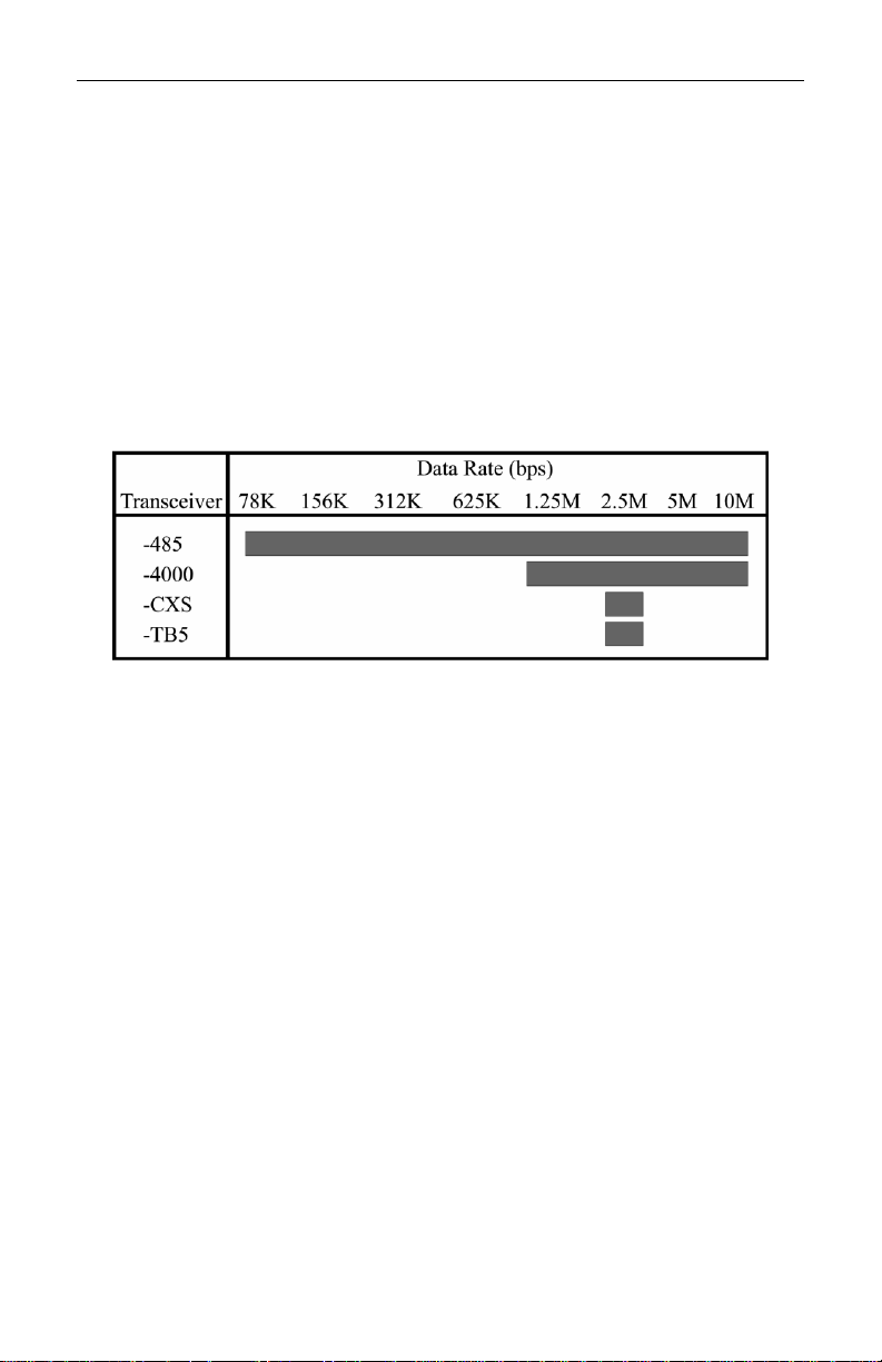
ARCNET Data Rates
Shipping Weight
1 lb. (.45 kg)
Compatibility
ANSI/ATA 878.1
USB 1.1 and USB 2.0
Regulatory Compliance
CE Mark
CFR 47, Part 15 Class A
LED Indicators
ARCNET Activity — green
USB — green
TD040900-0II
2
Page 3
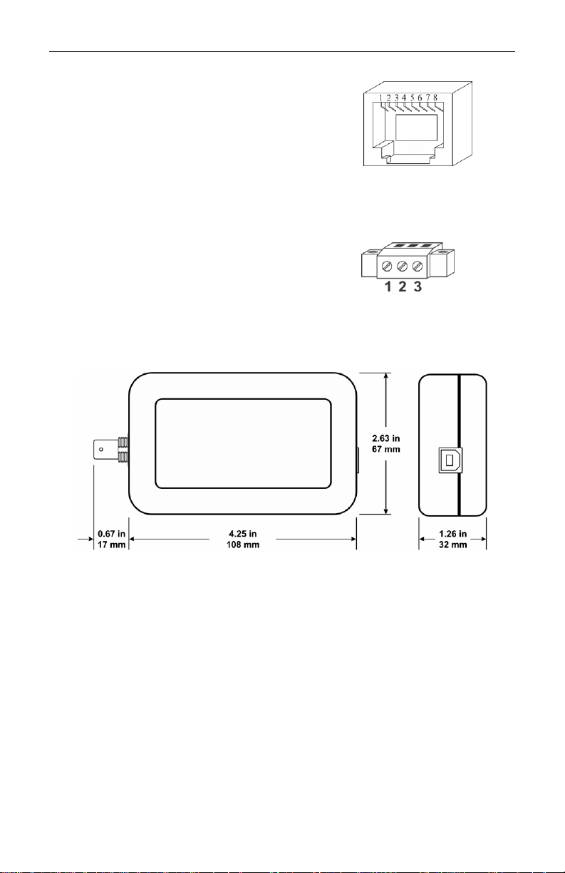
Figure 1 — RJ-45 Connector
Figure 2 — 3-pin Connector
RJ-45 Connector Pin Assignments
4000 485 TB5
4 Line Line – Line –
5 Line Line + Line +
(All other pins are unused.)
Screw Terminal Pin Assignments
4000 485
1 Line Line –
2 Shield Shield
3 Line Line +
Mechanical (The case dimensions shown below are valid for all models.)
ELECTROMAGNETIC COMPATIBILITY
All USB22 models comply with Class A radiated and conducted
emissions as defined by EN55022 and CFR 47, Part 15. This equipment
is intended for use in non-residential areas.
Warning
This is a Class A product as defined in EN55022. In a domestic environment
this product may cause radio interference in which case the user may be
required to take adequate measures.
Figure 3 — USB22-CXB Dimensions
TD040900-0II
3
Page 4

INSTALLATION
SOFTWARE
Driver installation instructions are provided in the readme file located on the
disk that accompanies the product.
INDICATOR LIGHTS
ARCNET: This LED will flash green in response to any ARCNET
activity.
USB: This LED glows green so long as a valid active USB
connection exists to an attached computer.
FIELD CONNECTIONS
The USB22 is available in four models that vary by transceiver type for
connecting to an ARCNET LAN via a particular kind of cable. Each
model’s transceiver is identified by the suffix (-4000, -485, -CXB or TB5) separated from the main number by a hyphen.
-CXB Coaxial Bus
Generally two types of coaxial cables are used with ARCNET: RG-62/u
and RG-59/u. RG-62/u is recommended because it matches the 93-ohm CXB impedance and can thus achieve the maximum 1000-foot segment
distance. Although RG-59/u does not match the -CXB impedance (it is
75-ohm cable), it will still work but the segment length may be limited.
Never attach coax cable directly to the USB22-CXB; always use the
provided BNC “T” connector. The “T” connector allows the coaxial bus
to continue as shown with device A in Figure 43. Apply the provided
93-ohm BNC terminator to the “T” if the USB22 terminates the coax in an
end-of-line situation as shown with device B in Figure 43.
Figure 4 — Possible Connections for the USB22-CXB
TD040900-0II
4
Page 5

-TB5 Twisted-pair Bus
The -TB5 transceiver accommodates twisted-pair cabling via a pair of
RJ-45 jacks which allow the unit to be daisy-chained at any location on
the bus segment Usually IBM type 3 unshielded twisted-pair cable
(UTP) is used, but shielded cable (STP) can also be used to provide
continuous shielding between devices.
When the USB22-TB5 is located at the end of a bus segment, Apply the
provided 100-ohm terminator to the empty RJ-45 jack to match the cable
impedance.
-485 DC-Coupled EIA-485
Two models support DC-coupled EIA-485 segments. The USB22-485
provides dual RJ-45 jacks and the USB22-485/S3 offers a 3-pin screw
terminal. Each segment can be up to 900 feet of IBM type 3 (or better)
STP or UTP cable while supporting up to 17 nodes. Make sure the phase
integrity of the wiring remains consistent throughout the network. All
phase A signals on NIMs and hubs must connect together. The same
applies to phase B. Refer toFigure 1 Figures 1 and 2 for connector
wiring.
Termination
If the NIM is located at the end of a segment, apply 100 ohms of
termination. For the USB22-485, insert a terminator in its empty RJ-45
jack. For the USB22-485/S3, attach a resistor to its 3-pin connector.
Bias
Bias must also be applied to the network to prevent the differential
receivers from assuming invalid logic states when the signal line is
floated. Bias is provided on the USB22-485 by a set of 806-ohm pull-up
and pull-down resistors.
Ground
All devices on the segment should be referenced to the same ground
potential to achieve the common mode voltage (+/–7 Vdc) required for
the EIA-485 specification. A ground connection is not provided by the
NIM. It is assumed adequate grounding is supplied by the existing
equipment. Refer to the existing equipment user manual for a discussion of
grounding requirements.
TD040900-0II
5
Page 6

-4000 AC-Coupled EIA-485
The AC-coupled EIA-485 transceiver offers advantages over the DCcoupled version. No bias adjustments are needed and wiring polarity is
unimportant. Much higher common mode voltage levels can be achieved
with AC coupling because the transformer coupling has a breakdown
rating of 1000 VDC.
However, AC-coupling also has disadvantages. AC-coupled segments
are shorter (700 feet max) and are limited to 13 nodes compared to 17 for
DC-coupling. Also, AC-coupled transceivers operate only at 1.25, 2.5,
5.0 and 10 Mbps, whereas DC-coupled transceivers function over all
standard data rates.
Two models support AC-coupled EIA-485 segments. The USB22-4000
provides dual RJ-45 jacks, whereas the USB22-4000/S3 offers a 3-pin
screw terminal.
Cabling rules are similar to those for DC-coupled NIMs. Wire nodes in a
daisy-chain fashion. Refer toFigure 1 Figures 1 and 2 for connector pin
assignments. Termination should only be applied to devices located at
the two ends of the segment. Do not mix AC-coupled and DC-coupled
devices on the same segment; however, bridging the two technologies is
possible with active hubs that have appropriate transceivers.
TD040900-0II
6
Page 7

NEED MORE HELP INSTALLING THIS PRODUCT?
Technical documents, software drivers and utility programs can be
downloaded from www.arccontrol.com. When contacting one of our
offices by telephone, ask for Technical Support.
Warranty
Contemporary Controls (CC) warrants this product to the original purchaser for two years
from the product shipping date. Product returned to CC for repair is warranted for one
year from the date the repaired product is shipped back to the purchaser or for the
remainder of the original warranty period, whichever is longer.
If the product fails to operate in compliance with its specification during the warranty
period, CC will, at its option, repair or replace the product at no charge. The customer is,
however, responsible for shipping the product; CC assumes no responsibility for the
product until it is received.
CC’s limited warranty covers products only as delivered and does not cover repair of
products that have been damaged by abuse, accident, disaster, misuse, or incorrect
installation. User modification may void the warranty if the product is damaged by the
modification, in which case this warranty does not cover repair or replacement.
This warranty in no way warrants suitability of the product for any specific application.
IN NO EVENT WILL CC BE LIABLE FOR ANY DAMAGES INCLUDING LOST
PROFITS, LOST SAVINGS, OR OTHER INCIDENTAL OR CONSEQUENTIAL
DAMAGES ARISING OUT OF THE USE OR INABILITY TO USE THE PRODUCT
EVEN IF CC HAS BEEN ADVISED OF THE POSSIBILITY OF SUCH DAMAGES,
OR FOR ANY CLAIM BY ANY PARTY OTHER THAN THE PURCHASER.
THE ABOVE WARRANTY IS IN LIEU OF ANY AND ALL OTHER WARRANTIES,
EXPRESSED OR IMPLIED OR STATUTORY, INCLUDING THE WARRANTIES OF
MERCHANTABILITY, FITNESS FOR PARTICULAR PURPOSE OR USE, TITLE
AND NONINFRINGEMENT.
Returning Products for Repair
Return the product to the location where it was purchased by following
the instructions at the URL below:
www.ccontrols.com/rma.htm
DECLARATION OF CONFORMITY
Information about the regulatory compliance of this product can be found at
the URL below:
www.ccontrols.com/compliance.htm
June 2012
TD040900-0II
7
Page 8

[This page was deliberately left blank.]
TD040900-0II
8
 Loading...