

Page 1

QUICKLINK
A Line of External Fixed-Port Active Hubs for ARCNET® Local Area Networks
INST ALLA TION GUIDE
INTRODUCTION
The QuickLink (QL) Series of external fixed port hubs provides a low cost
method of expanding ARCNET local area networks. These eight-port hubs
provide the ultimate in reliability and flexibility for cabling ARCNET
networks. A hub allows for the addition of a segment and support for
distributed star topologies. The QL utilizes the same robust hub timing
electronics found in the Contemporary Controls (CC) MODHUB series for
modular active hubs. This includes precision delay line timing, digitally
controlled timers for dependable operation and reduced bit jitter. Also, a
watchdog timer is included to prevent hub lockup — eliminating the need
to recycle hub power in the event of extraordinary electrical disturbance.
The QL operates from low-voltage AC, requiring a power voltage source in
the range of 8 to 24 volts.
Active hubs increase the robustness of ARCNET networks. They maximize
the distance that can be achieved on each cable segment ⎯ up to 2000 feet
(610 m) feet on coaxial segments. They prevent interference to the network
by squelching reflections caused by open or shorted cable segments attached
to the hub. Unused hub ports need not be terminated. Active hubs allow for
a distributed star topology, thereby minimizing the cabling required in a
facility. Two or more QL hubs may be cascaded.
Page 2
SPECIFICATIONS
Environmental
Operating temperature: 0°C to +60°C
Storage temperature: –40°C to +85°C
Relative humidity: 10 to 95%, non-condensing
Regulatory Compliance
CE Mark
CFR 47, Part 15 Class A
Functional
Compliance: ANSI/A TA 878.1
Hub delay: 300 ns max @ 2.5 Mbps
Unlatch delay time: 5.9 µs max @ 2.5 Mbps
LED Indicators: ACTIVITY ⎯ green
Power Requirements
Input voltage: 8–24 Volts
Input power: 6 VA
Input frequency: 47–63 Hz
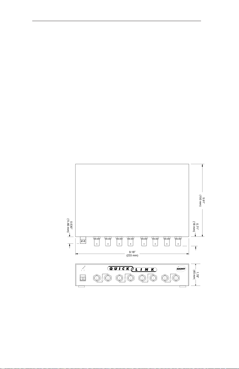
Mechanical
AC
INSTALLATION
The QL was designed as a desktop unit and should be installed on a stable
surface in a horizontal plane. Four rubber feet protect the mounting surface.
Power is derived from a nominal 24 VAC source, either a local power
supply or the wall-mounted transformer provided with the QL. This transformer is normally for a 120 VAC mains, but (-E) models are supplied with
a 230 VAC transformer.
TD990300-0IH
2
Page 3
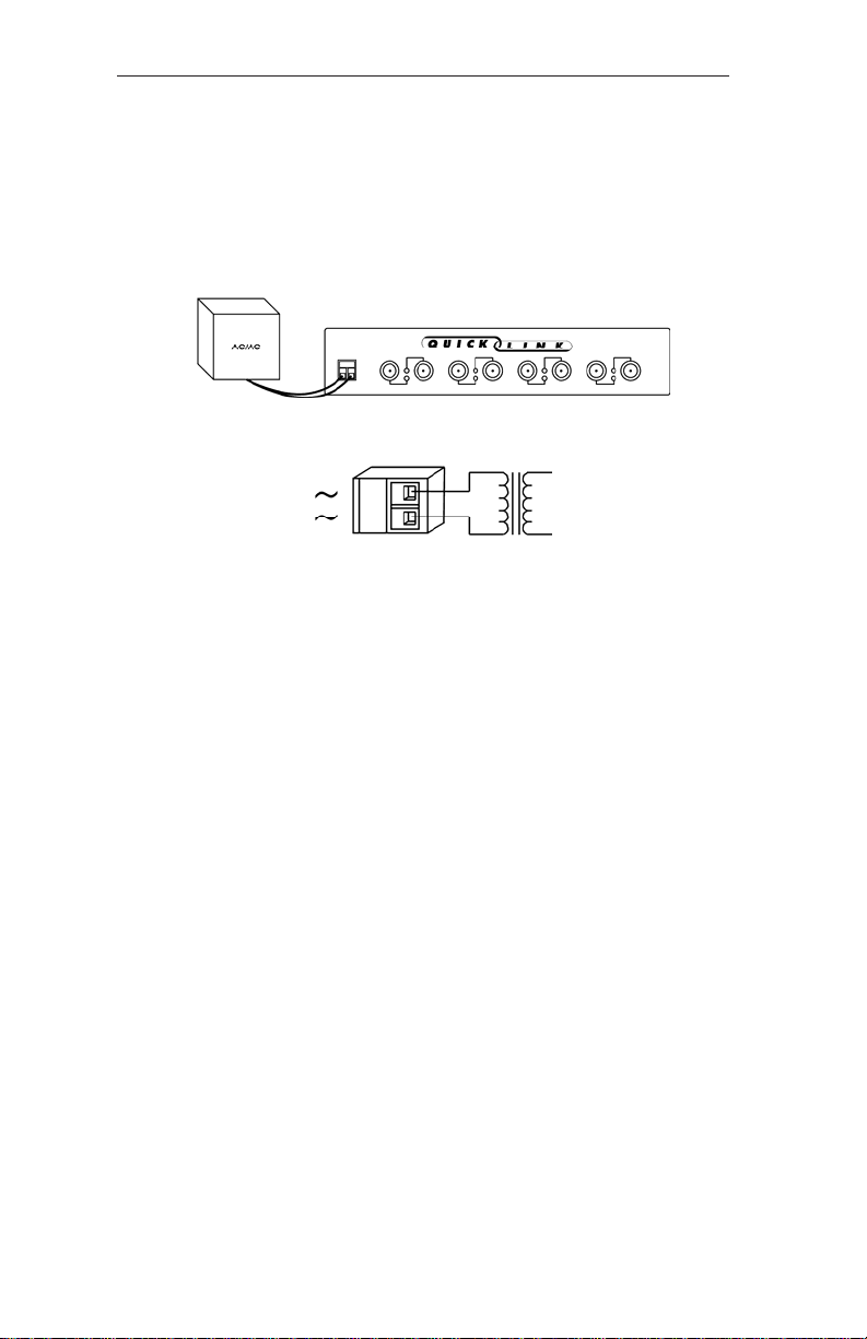
Each transformer comes with a 6-foot cord molded into the transformer. The
other end is stripped and tinned and must be secured to the two-position
removable connector located on the QL. With power removed from the
transformer, attach one wire to one of the terminals and the other wire to the
remaining terminal. Polarity of the wires is of no concern. Once wired,
plug the transformer into the appropriate wall socket to power up the QL.
Figure 1 — The QL can be powered by an external low-voltage transformer.
Figure 2 — The QL must have its companion transformer secondary
leads attached to its two-position removable connector.
The QL supports two transceiver types which are described below:
-CXS Coaxial Star
Typically, ARCNET is cabled with RG-62/u coaxial cable (with BNC
connectors) in a star topology. Each network interface module (NIM)
connects directly to a port on the QL hub. The coaxial star configuration
provides the longest coaxial distance and simplified troubleshooting. A
-CXS port effectively terminates the end of a coaxial bus segment without
the need of a passive terminator. With this configuration, the bus segment
can support up to eight NIMs with a maximum segment length of 1000 feet
(305 m).
-TPS Twisted-Pair Star
Unshielded or shielded twisted-pair wiring such as IBM Type 3 (#24 or #22
AWG solid copper twisted-pair cable or telephone wiring) can be used.
External BALUNs are not required since CC’s twisted-pair NIMs and hubs
have internal BALUNs. Twisted-pair is convenient to install; however, its
attenuation exceeds coaxial, its noise immunity is less, and its maximum
length between a node and a hub is lower. RJ-11 connectors are used with
this cable. A -TPS port effectively terminates the end of a twisted-pair bus
segment without the need of a passive terminator. With this configuration,
the bus segment can support up to eight NIMs with a maximum segment
length of 330 feet (100 m).
TD990300-0IH
3
Page 4

FIELD CONNECTIONS
The QL is available with two transceiver options. Each transceiver, which
is matched to a particular cable type, is identified by a three-character suffix
appended to the model numbers. The capabilities of each transceiver
differs. The QL is equipped with either the -CXS or -TPS option, however,
support for systems with either -CXB or -TPB is possible.
-CXS Coaxial Star
In a coaxial star system, NIMs and hubs are interconnected in a point-topoint fashion using coaxial cable. A NIM can connect to one other NIM or
can connect to an unused port on a hub. Hub-to-hub connections are allowed.
In a two-node system, simply connect the two -CXS NIMs together using
RG-62/u coaxial cable. The length of cable cannot exceed 2000 feet.
If more than two NIMs are used on a network, either an active or passive
hub is required. With passive hubs, a maximum of four NIMs can be
interconnected. Unused ports on the passive hub must be terminated with a
93 ohm (nominal) resistor. The maximum length between a passive hub port
and a NIM is 100 feet.
Active hubs provide overall better performance than passive hubs since
greater distances can be achieved along with a degree of isolation. Connect
each NIM to a port on the hub using RG-62/u coaxial cable. This length of
cable cannot exceed 2000 feet nor can the length of cable between two
cascaded hubs exceed 2000 feet. However, up to ten hubs can be cascaded,
thereby providing an overall cable length of 22,000 feet. Unused ports on
active hubs need not be terminated.
Figure 3 — Point-to-point connections
are required between -CXS NIMs and hubs.
TD990300-0IH
4
Page 5

-CXB Coaxial Bus
For hub-less systems, the -CXB transceiver can be used. NIMs are
interconnected with RG-62/u cables and BNC Tee connectors. Each -CXB
NIM represents a high-impedance connection in both the powered and
unpowered states. Therefore, passive termination must be applied to both
ends of a bus segment. Use BNC style 93 (nominal) ohm resistors at each
end. The maximum segment length is 1000 feet and the maximum number
of NIMs that can be connected to a segment is eight.
To extend a bus segment beyond 1000 feet, an active hub is required. If the
hub port is of the -CXS type, connection can be made if a few simple rules
are followed. Only connect this bus segment at the end of a segment. Do
not connect the hub to the middle of a segment since the hub port is not of
the high-impedance type. Do not terminate the end which attaches to the
hub port since a -CXS port effectively terminates the end of a bus segment.
Simply remove the BNC Tee connector and terminator from the segment end
and attach the cable directly to the hub port. The opposite segment end still
requires termination if no hub connection is being made.
Figure 4 — A hub is required to extend bus segments.
-TPS Twisted-Pair Star
In a twisted-pair star system NIMs and hubs are interconnected in a pointto-point fashion using either shielded or unshielded twisted-pair cable. A
NIM can connect to another NIM or to an unused port on a hub. Hub-to-hub
connections are allowed. A NIM such as the PCX-TPS can connect directly
to a QL-TPS port directly using a non-inverting cable.
Figure 5 — QL-TPS connected in a star configuration.
TD990300-0IH
5
Page 6

-TPB Twisted-Pair Bus
Like the -CXB transceiver, a hub-less cabling segment is possible. The
-TPB transceiver allows a total of eight -TPB NIMs to share a common bus
segment for up to 400 feet. These types of segments can be expanded using
the QL-TPS. Only connect this bus segment at the end of a segment. Do
not connect the hub to the middle of a segment since the hub port is not of
the high-impedance type. Do not terminate the end which attaches to the
hub port since a -TPS port effectively terminates the ends of a bus segment.
Simply remove the terminator from the segment end and attach the cable
directly to the hub port. The opposite segment end still requires termination
if no hub connection is being made.
Issue: the -TPS incorporates built-in BALUNs requiring a phase reversal of
the signals from the -TPB port. Therefore, the use of inverting cable is
required.
Figure 6 — A -TPB segment can be expanded using -TPS ports on a hub.
Wiring Chart
RJ-11 Connector
PIN -TPS -TPB
1 – –
2 N/C N/C
3 LINE+ LINE–
4 LINE– LINE+
5 N/C N/C
6 – –
Electromagnetic Compatibility
The QL series complies with Class A radiated and conducted emissions as
defined by CFR 47, Part 15 and EN55022. This equipment is intended for
use in non-residential areas.
Warning
This is a Class A product as defined in EN55022. In a domestic
environment this product may cause radio interference in which case
the user may be required to take adequate measures.
TD990300-0IH
6
Page 7

NEED MORE HELP INSTALLING THIS PRODUCT?
More information can be found on our web site at www.ccontrols.com. Browse
the Technical Support section of our site for a look at our on-line technical
manuals, downloadable software drivers and utility programs that can test
the product. When contacting us, just ask for technical support.
Warranty
Contemporary Controls (CC) warrants its new product to the original purchaser for two years from the product shipping date. Product returned to CC
for repair is warranted for one year from the date that the repaired product is
shipped back to the purchaser or for the remainder of the original warranty
period, whichever is longer.
If a CC product fails to operate in compliance with its specification during the
warranty period, CC will, at its option, repair or replace the product at no
charge. The customer is, however, responsible for shipping the product; CC
assumes no responsibility for the product until it is received.
CC’s limited warranty covers products only as delivered and does not cover
repair of products that have been damaged by abuse, accident, disaster, misuse, or incorrect installation. User modification may void the warranty if the
product is damaged by the modification, in which case this warranty does not
cover repair or replacement.
This warranty in no way warrants suitability of the product for any specific
application. IN NO EVENT WILL CC BE LIABLE FOR ANY DAMAGES
INCLUDING LOST PROFITS, LOST SAVINGS, OR OTHER INCIDENTAL
OR CONSEQUENTIAL DAMAGES ARISING OUT OF THE USE OR
INABILITY TO USE THE PRODUCT EVEN IF CC HAS BEEN ADVISED
OF THE POSSIBILITY OF SUCH DAMAGES, OR FOR ANY CLAIM BY
ANY PARTY OTHER THAN THE PURCHASER.
THE ABOVE WARRANTY IS IN LIEU OF ANY AND ALL OTHER
WARRANTIES, EXPRESSED OR IMPLIED OR STATUTORY, INCLUDING THE WARRANTIES OF MERCHANTABILITY, FITNESS FOR
PARTICULAR PURPOSE OR USE, TITLE AND NONINFRINGEMENT.
Returning Products for Repair
Return the product to the location from which it was purchased by following
the instructions at the URL below:
www.ccontrols.com/rma.htm
DECLARATION OF CONFORMITY
Information about the regulatory compliance of this product can be found at the
URL below:
www.ccontrols.com/compliance.htm
TD990300-0IH
7
Page 8

[This page was deliberately left blank.]
TD990300-0IH
8
 Loading...