

Page 1
Power Supply
NG4
110561-01
1. Description
The NG4 p ower supply supplies regulated direct voltage s for
supply ing power to the re spective devices of the prod uct family of I/O
compon ents. T he device supplies regulated dire ct voltage 24 V DC at
a power o f 16 watt s. A parallel op eration of se veral power su pply units
is not allo wed. The secondary vol tage can only be tapped at the right
side of the plug connector and at the screw-type terminals on th e top
of the module. The bus communic ation is lo oped through on both
sides of the plug connectors.
2. Important Notes
Declaration of Conformity
The device was tested according to the applicable standards. Conformity was proofed. The declaration of conformity is available at the
manufacturer BTR NETCOM GmbH.
Notes Regarding Device Description
These instructions include indications for use and mounting of the
device. In case of questions that cannot be answered with these instructions please consult supplier or manufacturer.
The indicated installation directions or rules are applicable to the
Federal Republic of Germany. If the device is used in other countries it
applies to the equipment installer or the user to meet the
national directions.
Safety Instructions
Keep the applicable directions for industrial safety and prevention of
accidents as well as the VDE rules.
Technicians and/or installers are informed that they have to
electrically discharge themselves as prescribed before installation or
maintenance of the devices.
Only qualified personnel shall do mounting and installation work with
the devices, see section “qualified personnel”.
8038/899243-01
The information of these instructions have to be read and understood
by every person using this device.
Symbols
Warning of dangerous electrical voltage
Danger
means that non-observance may cause risk of life,
grievous bodily harm or heavy material damage.
Qualified Personnel
Qualified personnel in the sense of these instructions are persons who
are well versed in the use and installation of such devices and whose
professional qualification meets the requirements of their work.
This includes for example:
• Q ualifi cation to connec t the dev ice accor ding to the V DE
speci fications and th e local regulations and a qual ification to put
this dev ice into op eration, to power i t down or to activate it by
respecting the internal directions.
• K nowledge of safety rules.
• K nowledge about applic ation and use of the de vice wi thin the
equipm ent sys tem etc.
3. Technical Data
Input
Operating volt age 110 - 240 V AC, 5 0 - 60 Hz
Internal fuse T1AL/ 250 V soldered fuse
Output
Output voltage DC +24 V (SELV)
Output current (max) 700 mA
Output power 16 W
Load and control a ccurac y ±3% (Tu = 20 °C)
Protection and monitoring
Continuous short
circuit protection yes
Idle test yes
Mains failure back up > 40 ms at 230 V AC and full lo ad
Dielectric strength 4000 V AC input/output
Device security
Standard Conformity was proofed.
The declaration of conformity is available
at the manufacturer BTR NETCOM GmbH.
Output Safet y Ext ra Low Volt age (SELV)
according EN 60950
Protection cl ass 2
EMV
CE conformity
Emitted interference/
Immunit y to inter ference the dev ice was tested acc ording to the
applicable standards; conformit y was
proofed, the declaration of conformity
is available at BTR N ETCOM
Contacting
Primar y and se condar y screw t ype terminal bl ocks
Cover no
Type of protection IP20 (nach EN 60529)
Wire cross sec tion 1.5 mm
Housing
Dimens ions WxHxD 1.968 x 2.756 x 2.559 in.
50 x 70 x 65 mm)
Front dimension 1.772 in. / 45 mm
Weight 108 g
Mounting position any
Mounting standard rail TH35 per IEC 60715
Material
Housi ng Polyamide 6.6 V0
Terminal blocks Polyamide 6.6 V0
Cover plate PolycarbonateB
Mounting in series without space
Type of protection
(IEC 60529)
Housing IP4 0
Terminal blocks IP20
Terminal blocks
Wire cross sec tion max . AWG 12 (4.0 mm²) solid wire
max. AWG 14 (2.5 mm²) stranded wir e
Wire diameter min. 0.3 mm up to max 2.7 mm
Temperature range
Operation -10 °C to +55 °C
Storage -25 °C to +85 °C
2
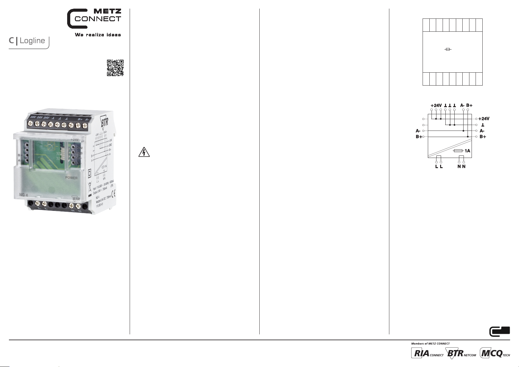
4. Connection Diagram
⊥ ⊥ ⊥
+24V
+24V
+24V
L N
Operating voltage
110 - 240 V AC
1 A
+24V
Output voltage
24 V DC
0,7 A
L N
L N
5. Wiring Diagram
B+
A-
METZ CONNECT GmbH
Im Tal 2 | 78176 Blumberg | Germany | Phone +49 7702 533-0 | Fax +49 7702 533-433
Mounting instruction see www.metz-connect.com
Page 2
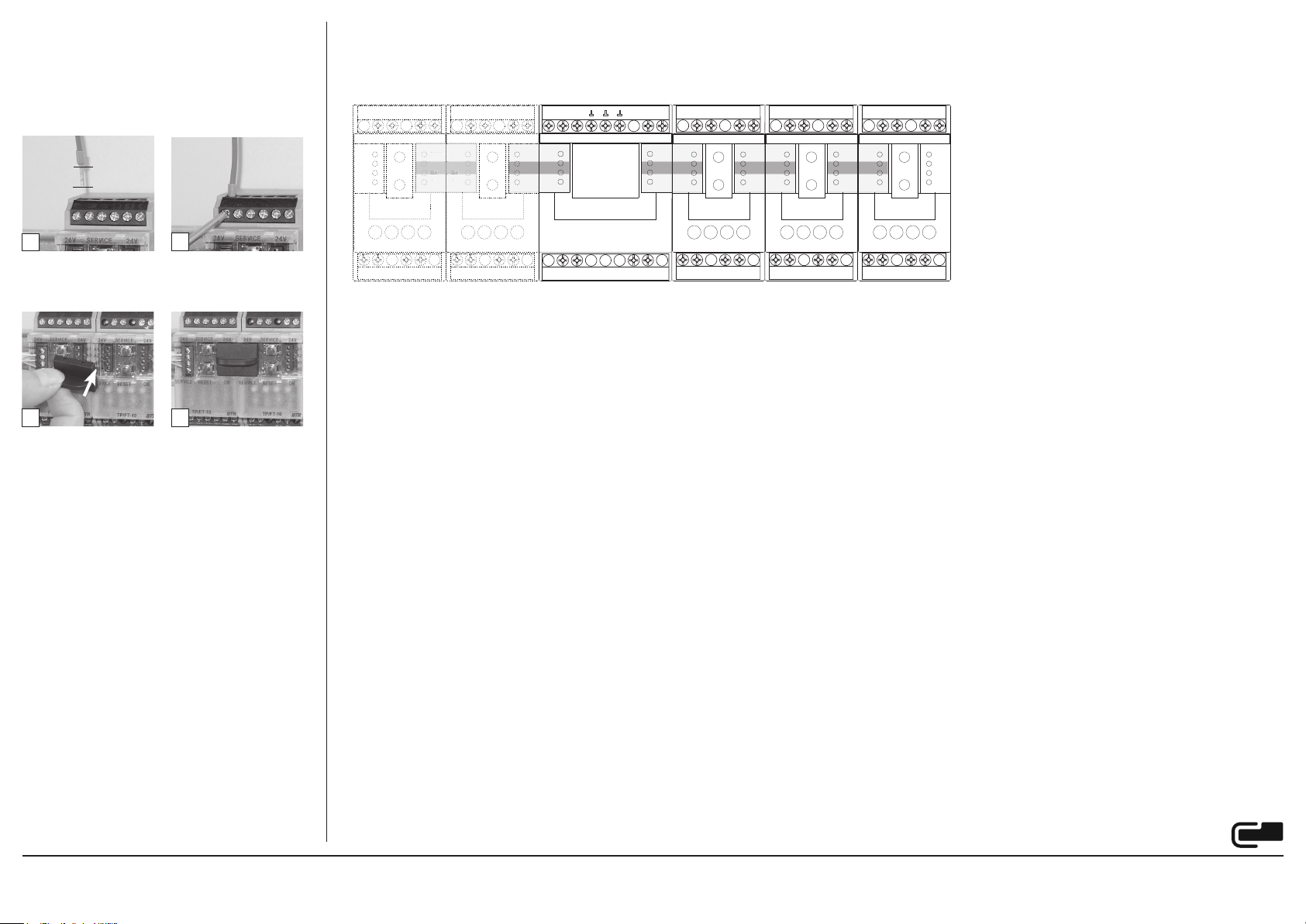
6. Mounting
B+A-B+
A-
24 V
GND
GND
No 24 V DC transmission!
No 24 V DC transmission!
24 V DC output voltage
L / N operating voltage 110-240 V AC
Power down the equipment
Mount the module on s tandar d rail (T H35 per IEC 60715 in
junction boxes and/or on distribution panels).
Installation
Electric installation and device termination shall be done by
qualified persons only, by respecting all applicable specifications
and regulations.
7 mm
7. Termination possibility
• C onnec tion on the right side of the NG4 for voltage feeding and bus t ap to the following b us module s (with jumper conn ection for example)
• C onneciton on the l eft side of the NG4 transfe r of the bus co nnection by jump er conne ction. No 24 V DC connectio n!
• P arallel connec tion of several NG4 devices is not possible.
3+
3-
4+
4-
4+
4-
24V 24V 24V
3+
3-
TTT
B+
A-
A- B+
+24V
4-
24V24V 24V24V 24V24V24V 24V24V 24V
24 V
24 V24 V 24 V24 V 24 V
GND
GNDGND GNDGND GND
B+
B+B+ B+B+ B+
A-
A-A- A-A- A-
3+
3-
4+
4-
24 V24 V 24 V24 V 24 V
GNDGND GNDGND GND
B+B+ B+B+ B+
A-A- A-A- A-
3+
3-
4+
4+
4-
3+
3-
1
Preparing cable for connection.
Strip the w ire by 7 mm, at tach an end slee veif ne cessary, insert
the wire into the contact and tighten the terminal screw w ith a
screw drive r.
3
• T he modul e can be ali gned without interspace. Use the jumper
plug to connect b us and supply voltage when the module s are
mounte d in series.
• T he maximum quanti ty of modules connecte d in line is limited
to 15 or to a maximum power co nsumption of 2 Amps ( AC or
DC) per connec tion to the power sup ply. For any s imilar block of
additi onal modules a sep arate connecti on to the power suppl y is
mandatory.
2
4
NG4
L
2+
1+
2-
1-
2+
1+
2-
1-
L
N N
2+
1+
2-
1-
2+
1+
2-
1-
2+
1+
2-
1-
METZ CONNECT GmbH
Im Tal 2 | 78176 Blumberg | Germany | Phone +49 7702 533-0 | Fax +49 7702 533-433
Mounting instruction see www.metz-connect.com
 Loading...