

Page 1
Digital Input Module
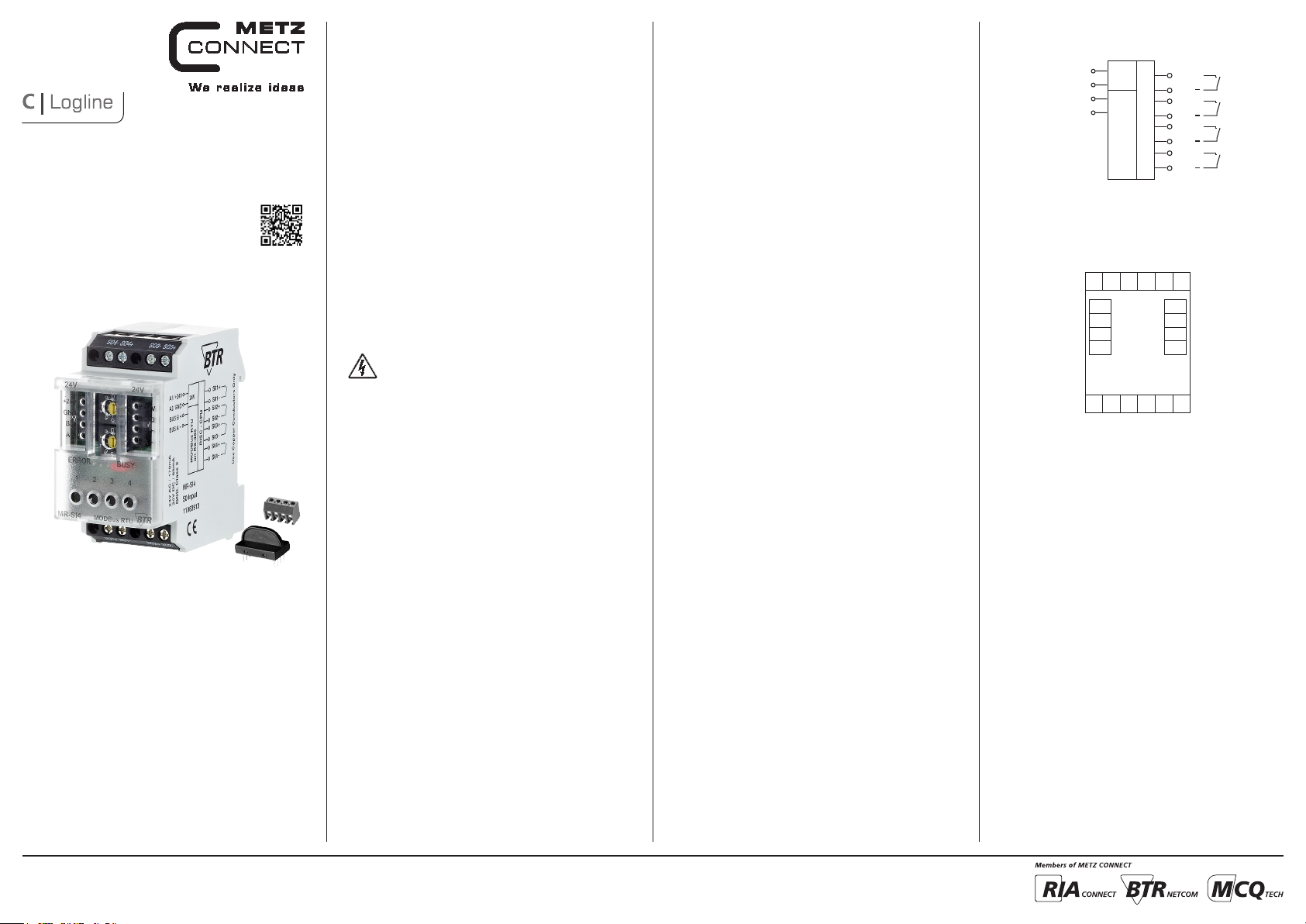
MR-SI4
110 83913
1. Description
The Modbus module with 4 S0 inputs to DIN EN 62053 -31 class A
was deve lope d for dec entral ized sw itchin g task s. It is suitable for
countin g S0 counter pulses. This allows very good inte gration of the
module into an energy cont rolling system. In case of a power failur e,
the last counter r eadings are saved. The inputs c an be scanned
by means of standard obje cts v ia a Modbus maste r. The module
address, the baud rate and the parity are set by me ans of tw o
address switches on t he front.
Suitab le for de centra lized mounting in serial sub-distributor.
2. Declaration of Conformity
The dev ice was te sted according to the applicab le standards. Conformit y was proofed. T he declaration of conformity is available at
the manufacturer METZ CONNECT GmbH.
Notes Regarding Device Description
These instructio ns include indic ations for use and m ounting of the
device. In case of questions tha t cannot b e answe red wi th these
instructions please consult supplier or manufacturer.
The indi cated instal lation direc tions or r ules ar e applic able to the
Federal Republic of Ge rmany. If the device is used in other countries
it applies to the e quipme nt inst aller or the user to meet the
national directions.
Safety Instructions
8096/899360
Keep th e applic able direct ions for industr ial safety and preve ntion of
accide nts as we ll as the VDE rule s.
Technicians and/or installer s are informed that they have to
elec tric ally dis charge t hemse lves as presc ribed before installation or
mainten ance of the devices.
Only qualifie d pers onnel shall do mo unting an d installatio n work
with the devices, se e sec tion “qualified pers onnel”.
The information of thes e instr uctions have to b e read and understood by ever y person usin g this device.
Symbols
Warning of dangerous electrical voltage
Danger
means that non-observance may cause risk of life,
grievous bodily harm or heavy material damage.
Qualified Personnel
Qualif ied pe rsonnel in the sense of these instructions are per sons
who are well ver sed in the use and installation of such dev ices an d
whose p rofes sional qualifi catio n meet s the re quirem ents of their
work.
This includes for example:
• Qualif icati on to connect th e device according to the V DE
speci fications and the loc al regulations and a qualificat ion to put
this dev ice into operation, to pow er it dow n or to activate it by
respecting the internal directions.
• Knowledge of safet y rule s.
• Knowledge about app lication and us e of the device within the
equipm ent sy stem etc.
3. Technical Data
Modbus Interface
Protocoll Modbus R TU
Transmission rate 1200 ... 115200 Bd
(factory se tting 19200 Bd Even)
Cabling RS485 two wire bus wi th volt age
equalizing cable in bus / line topol ogy
terminate with 120 Ohms
Supply
Operating voltage range 20 ... 28 V AC/ DC (SELV)
Current consump tion 170 mA (AC) / 65 mA (DC)
Relative dut y cycl e 100 %
Input
4x S0 input according to DIN EN 62053-31 Class A
Housing
Dimens ions Wx HxD 1.4 x 2.8 x 3.0 in. (35 x 70 x 65 mm)
Weight 95 g
Mounting position any
Mounting standard rail T H35 per IEC 60715
Mounting in series the ma ximum quantit y of modul es
with out s pace connected in line is limited to 15 or
to a maximum power consumption of
2 Amps ( AC or DC) per conn ection to
the pow er supply. For any similar
block of additional modules a
separate connection to the power
supply is mandatory.
Material
Hous ing Polyamide 6.6 V0
Terminal blocks Polyamide 6.6 V0
Cover plate Polycarbonate
Type of protecti on
(IEC 60529)
Housing IP4 0
Terminal blocks IP20
Terminal blocks
Supply and bus
4 pole terminal block max. AWG 16 (1.5 mm²) sol id wire
max. AWG 18 (1.0 mm²) str anded w ire
Wire diameter min . 0.3 mm up to ma x. 1.4 mm
(terminal block and jumpe r plug are
included to each packing unit)
Module connection
Inp ut /Output max. AWG 12 (4.0 mm²) s olid wire
max. AWG 14 (2.5 mm²) stranded w ire
Wire diameter min . 0.3 mm up to ma x 2.7 mm
Temperature range
Operation -5 °C ... +55 °C
Storage -20 °C ... +70 °C
Protective circuit ry polari ty revers al prote ctio n of
operating voltage
polarity re vers al prote ction of suppl y
and bus
Display
Operating and bus acti vity gree n LED
Error ind ication red LED
Status of the input s yellow LED
4. Wiring Diagram
A1/ +24V
A2/ GND
BUS B+
BUS A-
24V AC / 170mA
24V DC / 65mA
24V
Modbus RTU
5. Connection Diagram
S04-
S04+
24 V AC/DC
+24V
GND
B+
BUS B+
A-
S01-
S01+
on RS-485
GND
BUS A-
S01+
S01
S02+
S02
S03+
RISC - CPU
S03
S04+
S04
S03-
S03+
+24V
GND
B+
A-
S02+
S02-
METZ CONNECT GmbH | Im Tal 2 | 78176 Blumberg | Germany | Phone +49 7702 533-0 | Fax +49 7702 533-433
Mounting instruction see www.metz-connect.com
Page 2
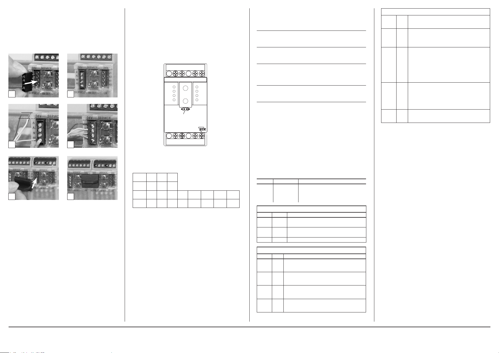
6. Mounting
Power down the equipment.
Mount the module on standard rail ( TH35 pe r IEC 60715 in
junction boxe s and/o r on distr ibution panels).
Installation
Electric installation and device termination shall be done by quali-
fied persons only, by re spec ting all applic able
specifications and regulations.
Plug in the terminal block for bus connection.
21
Connect the cable for bus supply.
5 mm
43
Mounting in series.
65
The module can be aligne d witho ut inter space. Use the jumper plug
to conne ct bus an d supply volta ge when t he modules are mounted
in seri es.
The max imum qua ntity of modules connecte d in line is limited
to 15 or to a maximum powe r consumption of 2 A mps (AC o r
DC) pe r conne ction to the power suppl y. For any similar block of
additional modules a separate connection to the power supply
is mandatory.
7. Bit rate and Parity setting
The bit rate and parity c an be set in the pro gramming mode wh en
ajumper is plugged behind the front cover of the module. This
jumper is removed in normal mode. A c onnec tion to the bus is not
required during bit rate setting.
The bit rate of the mo dules c an be se t in the following way:
1. r emove the front cover of th e module;
2. plug a jumper to the two middle pins of the 4 pole header
betw een the red and green L ED (Á);
3. set th e desired pari ty and b it rate with the address s witches (Â )
in accordance to the chart b elow.
S03+
S03-
S04+
S04-
x10
x1
BUSY
S02+
+24V
GND
B+
A
-
S02-
24V 24V
+24V
GND
B +
A
-
ERROR
Jumper below
1
the faceplate
A
O
MR-SI4
MODBus RTU
S01+
S01-
4. switch on the supply voltage of t he module; it is now p erman ently savi ng the bit rate in an EEPROM;
5. switch off th e supply voltage of the mo dule;
6. remov e the jump er from t he head er and place the fr ont cove r.
Switch
1 2 3
x10
Parity even odd none
Switch
1 2 3 4 5 6 7 8
x1
Bitrate
1200 2400 4800 9600 19200 38400 57600 115200
(Bit/s)
If the settings differ from the settings specified in the chart the factory
setting applies.
Factory setting: 19200 Bd Even
8. Software Description
8.1 I/O Commands
“02 (0x02) R ead Dis crete I nputs ”
Reque st
Valid Input Starting Address 0 .. 3
Valid Quantity of Inputs 1 .. 4
Response
Byte Count 1
Input Status Bit0 .. Bit3 ( Bit4 .. Bit7 = 0 )
Information
1 = Status Input closed
0 = Status Input open
“04 (0x 04) Read Input R egist ers”
Request
Valid Register Starting Address 20
Valid Quantity of Registers 1
Response
Byte Count 2
(Tabulator kontrollieren )
8.2 Modbus functions
The following f unctions are us ed to read or wri te the registers. The
valid address r anges are indic ated in br acket s.
Read Input Registers (0-20)
Read Holding Registers (0-43)
Write Single Register (20-43)
Write Single Register (65)
Write Multiple Registers (0-43)
For long data ty pes with a length of several re giste rs, these re gisters
are listed dire ctly o ne after the oth er and the one with the highest
value are indicated fir st. This data c an only be transmi tted in complete form.
Discrete Inpu ts (Read-O nly)
Address
Name Description
0 – 3 INPUT
Input Register (Read-Only)
Address Name Description
0 – 11 IZ
12 – 19 BZ
20 INPUT Bits 0 -3 contain Discrete Input 0-3
Holding Register
Address Name Description
0 – 11 IT
12 – 19 AZ
20 – 23 IE
24 – 27 WI
Switchi ng stat us of the inputs
(switches are connected),
0: Off (s witch is open), 1: On
(switch is clos ed)
Pulse counter
Data type uint48_t (3 registers ea ch)
Calculated counter reading
Data type uint48_t (2 registers ea ch)
Copy of th e pulse counter af ter hav ing pre ssed
the key
Data type uint48_t (3 registers each) (EEPROM)
Initial count
Data type uint 32_t (2 registers each)
Factor y set ting 0 (EEPROM)
Pulse s per unit
Data type uint16_t (1 re giste r each)
Factor y set ting 1 (EEPROM)
Current conversion factor
Data type uint16_t (1 re giste r each)
Factor y set ting 1 (EEPROM)
(continued) Description of the software
28 – 31 WU
32 – 35 WP
36 – 39 ZS
40 – 43 TA
65 BAUD
8.3 Operating mode for calculation with conversion
factor
In the WP register, there is a code 0…1 that determines, together
with the conver sion fa ctor s WI and WU, the way how they are
included in the c alculation. WP, WI and W U depend on whe ther
the converters are switche d by the co unters, whet her the counter
indicates the consumption in a primary or secon dary way and whe ther the emitted puls es correspo nd primarily or s econdarily to the
consumption.
A diffe rence m ust be made bet ween the follo wing el ectricit y meter
types:
Type 1: Directly measur ing coun ter, displ ay: prim ary,
pulse: primar y
Note: Indicates the actual consumption
Species: DIN rail counter with mechanical drum-type counting
mechanism, Ferraris counter
Type of formula: WP = 0
Factors: WI = WU = 1
BZ = (---- -- --- - + AZ ) ∙ WI ∙ WU , BZ = counter rea ding = cons umption
Type 2: Conve rsion counter, display: p rimar y, pulse: s econdary
Note: Indicates the actual consumption
Species: Counter with LCD display
Type of formula: WP = 1
Factors: WI and WU correspond to the converters
BZ = (---- -- --- - ∙ WI ∙ WU) + AZ , BZ = counter re ading = consumpti on
Type 3: Conve rsion counter, display: p rimar y, pulse: p rimar y
Note: Indicates the actual consumption
Species: Counter with LCD display, multi-function meters
Type of formula: WP = 0
Factors: WI = WU = 1
BZ = (---- -- --- - + AZ ) ∙ WI ∙ WU , BZ = counter rea ding = cons umption
Voltage conversion factor
Data type uint16_t (1 re giste r each)
Factor y set ting 1 (EEPROM)
Operating mode for calculation with conversion factor
Data type uint16_t (1 re giste r each, on ly bit 0 valid)
Range of v alues 0…1, see bel ow
Factor y set ting 0 (EEPROM)
Format of the counter digit display
Data type uint16_t (1 re giste r each) (EEP ROM)
High by te for counter digi ts,
Range of values 0…9, fac tory s etting 7,
hi gher values are limited to 9
Low by te for pla ces af ter the decimal p oint,
Range of values 0…3, factor y set ting 1,
hi gher values are limited to 3
Flag for key activatio n
Data type uint16_t
(1 register each, f lag in bit 0 only)
0: key is locked,
1: key is operational
factory setting 1 (EEPROM)
Codes f or baud rates and p arity
Factor y set ting 19200 baud, Even Parity (EEPROM)
IZ – IT
IE
IZ – IT
IE
IZ – IT
IE
METZ CONNECT GmbH | Im Tal 2 | 78176 Blumberg | Germany | Phone +49 7702 533-0 | Fax +49 7702 533-433
Mounting instruction see www.metz-connect.com
Page 3

(continued) Description of the software
Type 4: Conversio n counte r, display: secon dary, pu lse: se condar y
Note: Indicates the consumption reduced by the converter factors
Species: DIN rail counter with mechanical
drum-type counting mechanism, Ferraris counter
Type of formula: WP = 0
Consumption and display of the conve rter counter are different .
Both can be calculated using a dif ferent confi guration (WI, WU).
Factor s: W I = WU = 1:
The cal culate d counte r reading corre spond s to the display
of the conv erte r counte r.
Factor s: W I and WU corresp ond to the conver ters:
The cal culate d counte r reading corre spond s to the
consumption.
IZ – IT
BZ = (---- -- --- - + AZ ) ∙ WI ∙ WU , BZ = counter reading or consumption
IE
8.4. Commissioning
The use r reads on site the initial count from the ele ctri city m eter and
presses the key on the MR-SI4. Af ter this key press, the pulse counter
of regis ter IZ is copied into register IT.
Afterwards, the user configures t he MR-SI4 v ia the Mo dbus usin g a
service program. The following mus t be ente red:
• initial count read from the counter
• pulses per unit,
e.g. indic ation on t he ele ctri city m eter 2000 puls es per k Wh
• formula type for calculation with converter factors
• factor for current conversion,
e.g. indic ation on t he conve rter 200/5A → factor = 40
• factor for voltage conversion,
e.g. indic ation on t he conve rter 20000 /100V → fac tor = 200
• number of digits and places after the de cimal po int
• deactivate the key to pr otect the IT re giste r
8.5.Details for calculation
The cal culate d counte r reading should behave e xac tly in the same
way as the e lectricity meter. This requires that ther e should be no
overflows and rounding off e rror s for the interme diate re sults .
There fore, partic ularly large dat a typ es are us ed for co unting an d
calculation.
Every 60 millisecon ds, a puls e can be emitte d by the electricit y mete r.
This re sults in up to 1,440,0 00 puls es per day or abou t 526,000,000
pulse s per year.
If the pulse counter was realized w ith 4 by tes, it c ould be count to
4,294,967,295. At highes t pulse f reque ncy, this would be e nough for
approx . 8.2 years.
There fore it is realized with 6 b ytes and cann ot over flow.
The numb er of places after the de cimal point is considered as an ad -
ditional multiplier with a powe r of ten dur ing the c alculation.
Furth ermor e, it dete rmine s the place of the de cimal point in the
display of BZ and A Z.
As for the elec tric ity co unter which only h as a specifie d number of
decimal place s, the number of places is limited w ith the last step in
the calculation. This is w hy the ca lculated counter reading of the MRSI4 over flows to 0 as of ten as the c ounter reading of the ele ctricity
meter.
Calculated co unter reading, if WP is 0.
BZ = ( (uint96 _t) (IZ - IT)*WU*WI*Power of te n [place s after decimal
point] / IE +
(uint96_t) A Z * WU * WI )
% power of ten [digits]
Calculated co unter reading, if WP is 1.
BZ = ( (uint96 _t) (IZ - IT)*WU*WI*Power of te n [place s after decimal
point] / IE +
(uint96_t) A Z )
% power of ten [digits]
(continued) Description of the software
8.6 Bit rate setting with Modbus command
Parity and bit rate have the same value as when setting them by
address switch.
If Parity or Bit has the value 0, no setting or storage is carried out.
The register content is stored in the EEPROM.
“06 (0x06) Write Single Register”
Request
Valid Register Address 0x41 ( 65 )
Valid Register Value 2 Bytes
15 14 13 12 11 10 9 8 7 6 5 4 3 2 1 0
0x53 Parität Bitrate
Bit 15-8: Magic-Number 0x53 = 83 as protection against
accidental writing.
The command will be further analysed only with this number.
Bit 7-4 1 2 3
Parität even odd none
Bit 3-0 1 2 3 4 5 6 7 8
Bitrate 1200 2400 4800 9600 19200 38400 57600 115200
Response
Echo of Request
Example for a frame:
Slave address 0x12 Setting of rotary switch (18)
Function 0x06 Write Single Register
Register address Hi 0x00
Register address Lo 0x41 Bit rate and parity (65)
Register contents Hi 0x53 Magic-Number
Register contents Lo 0x15 Parity Even, 19200 Baud
All dev ices c an be switched simultaneously wit h a Broadcast co mmand (Slave addre ss 0x00) Howe ver, it is advised not to do so as this
can cause problems:
- Devices from other manufacturers may have under this
address a register for a different purpose that will then
be operated in the wrong way.
- There is no feedback from the individual devices.
Consequently the control cannot immediately recognize
if the command was correctly received.
It is safe r to addre ss and s witch e ach dev ice indi vidually.
The dev ice will then ans wer wi th the old sett ings of parity and bit
rate. Switching will take place only afterwards. Howe ver, the ans wer
can get l ost if th e bus is dis turbe d.
When all devices are switche d; it is adv ised to check communic ation.
Any func tion of the device prov iding a fe edback is suit able. If a single
funct ion is to be u sed be ing inde pendent from t he process pe riphery
then the funct ion „Diagnost ic“ sub -func tion „R eturn Q uery Data“ is
suitab le, it returns the transf erre d data.
If bit rate and pari ty se tting of a devic e are unkn own it is p ossible to
address the device successively w ith all combinations of bit rate and
parit y until the device answe rs. Try t he most l ikely combinations fir st.
Try the low er bit rates last as they t ake longer.
(continued) Description of the software
8.7 General Commands
“08 (0x08) Diagnostics”
Subfunc tion “0 ( 0 x00 00) Re turn Query Data”
Data Field Any
Response: Echo of Request
Subfunction “1 (0x0001) Restart Communication Option”
Data Field 0x0000 oder 0xFF00
Response: Echo of Request
Action: Clears all Error Counters, Restarts node
Subfunc tion “4 (0x 0004) Force L isten Only Mode”
Data Field 0x0000
No Response
Action: No response until Node Reset or Function Code 08
Subcode 01
Subfunc tion “10 ( 0x 000A ) Clear Counters”
Data Field 0x0000
Response: Echo of Request
Action: Clears all Error Counters
Subfunc tion “11 ( 0x000B) Re turn Bus M essage Count”
Data Field 0x0000
Response: Quantity of messages that the remote device has
detected on the communications system since its last restart,
clear counters operation, or power-up.
Subfunc tion “12 ( 0x0 00C ) Retur n Bus Communication Erro r Count ”
Data Field 0x0000
Response: Quantity of errors encountered by the remote
device since its last restart, clear counters operation,
or power-up. (CRC, Length <3, Parity, Framing)
Subfunc tion “13 ( 0x0 00D) Return Bus Exception Error Count ”
Data Field 0x0000
Response: Quantity of MODBUS exception responses returned
by the remote device since its last restart, clear counters
operation, or power-up.
Subfunc tion “14 (0x 000E) Retur n Slave Me ssage Count ”
Data Field 0x0000
Response: quantity of messages addressed to the remote
device, or broadcast, that the remote device has processed
since its last restart, clear counters operation, or power-up.
Subfunc tion “15 (0x000F ) Return Slave No Respo nse Count”
Data Field 0x0000
Response: Quantity of messages addressed to the remote
device for which it has returned no response (neither a normal
response nor an exception response), since its last restart, clear
counters operation, or power-up.
(continued) Description of the software
“43 /14 (0x2B / 0x0E) Read Device Identification”
Request
Read Device ID code: 0x01
Object ID 0x00
Response
Device ID code 0x01
Conformity level 0x01
More follows 0x00
Next object ID 0x00
Number of objects 0x03
Object ID 0x00
Object Length 0x03
Object Value “BTR”
Object ID 0x01
Object Length 0x06
Object Value “MR-SI4”
Object ID 0x02
Object Length 0x04
Object Value “V2.0”
METZ CONNECT GmbH | Im Tal 2 | 78176 Blumberg | Germany | Phone +49 7702 533-0 | Fax +49 7702 533-433
Mounting instruction see www.metz-connect.com
 Loading...