

Page 1
Analog Input Module
MR-AI8
11083213
1. Description
The Modbus module with 8 individually configurable
resistance or voltage inputs is designed for local switching
operations. It is suitable to record resistance or voltage values of
for example passive and active temperature sensors electrical
ventilation or mixing valves, valve positions etc. The inputs are
universally configurable and can be scanned via a Modbus-Master.
Setting of the slave address, bit rate and parity is done with the
two address switches (x1 / x10) on the front. Possible settings
are addresses 00 to 99 and baud rates 1200, 2400, 4800, 9600,
19200, 38400, 57600 und 115200 Bd.
The device does not participate in bus communication if the
address is 00 (reserved for broadcast commands).
2. Declaration of Conformity
The device was tested according to the applicable standards.
Conformity was proofed. The declaration of conformity is
available at the manufacturer BTR NETCOM GmbH.
Notes Regarding Device Description
These instructions include indications for use and mounting of
the device. In case of questions that cannot be answered with
these instructions please consult supplier or manufacturer.
The indicated installation directions or rules are applicable to
the Federal Republic of Germany. If the device is used in other
countries it applies to the equipment installer or the user to
meet the national directions.
Safety Instructions
Keep the applicable directions for industrial safety and prevention of accidents as well as the VDE rules.
Technicians and/or installers are informed that they have to
electrically discharge themselves as prescribed before installation or maintenance of the devices.
Only qualified personnel shall do mounting and installation
work with the devices, se e section “qualified personnel”.
The information of these instruc tions have to be read and understood by every person using this device.
7170/899289
Symbols
Warning of dangerous electrical voltage
Dange r
means that non- obser vance may cause risk of life,
grievous bodily harm or he avy material damage.
Qualified Personnel
Qualified personnel in the sense of these instructions are
persons who are well versed in the use and installation of such
devices and whose professional qualification meets the requirements of their work.
This includes for example:
• Qualification to conne ct the device according to the VDE
specifications and the local regulations and a qualific ation to
put this device into operation, to power it down or to activate
it by respecting the internal directions.
• Knowledge of safety rules.
• Knowledge about application and use of the device within the
equipment system etc.
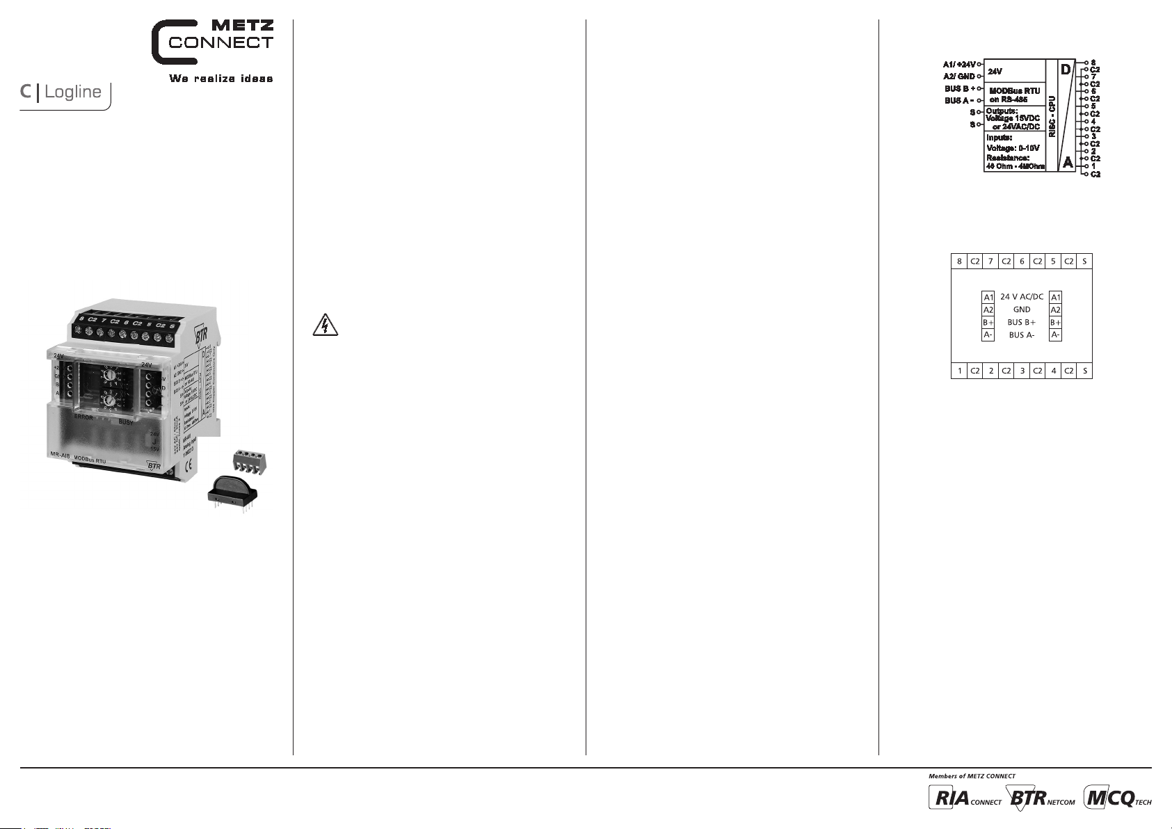
Modbus Interface
Protocoll Modbus RTU
Transmission rate 1200 ... 115200 Bd
(factory set ting 19200 Bd Even)
Cabling RS485 two wire bus with voltage
equalizing cable in bus / line
topology
Supply
Operating volt age range 20 ... 28 V AC/DC (SELV)
Current consumption 65 mA (AC) / 25 mA (DC)
Relative duty cycle 100 %
Input
Resistance range 40 W to 4 MW
Voltage input 0 ... 10 V DC
Resolution 1 mV
Error
Voltage input about ±10 mV
Resistance input < 12 kW = 0,1 % / > 12 kW = 1 %
Housing
Dimensions Wx HxD 2.0 x 2.8 x 2.6 in. (50 x 70 x 65 mm)
Weight 104 g
Mounting position any
Mounting standard rail TH35 per IEC 60715
Mounting in series the maximum quantit y of modules
without space connected in line is limited to 15 or to
a maximum power consumption of
2 Amps (AC or DC) per conne ction to
the power supply.
For any similar block of additional
modules a separate connection to the
power supply is mandatory.
Material
Housing Polyamide 6.6 V0
Terminal blocks Polyamide 6.6 V0
Cover plate Polycarbonate
Type of protection
(IEC 60529)
Housing IP40
Terminal blocks IP20
Terminal blocks
Supply and bus
4 pole ter minal block max. AWG 16 (1,5 mm²) solid wire
max. AWG 18 (1,0 mm²) stranded wire
Wire diameter min. 0.3 mm up to max. 1.4 mm
(terminal block and jumper plug are
included to each packing unit)
Module connection
Input/Output max. AWG 12 (4.0 mm²) solid wire
max. AWG 14 (2.5 mm²) stranded wire
Wire diameter min. 0.3 mm up to max 2.7 mm
Temperature range
Operation -5 °C ... +55 °C
Storage -20 °C ... +70 °C
Protective circuitr y polarity reversal protection of
operating voltage
polarity reversal protection of supply
and bus
Display
Operating and bus activity green LED
Error indication red LED
4. Wiring Diagram3. Technical Data
5. Connection Diagram
METZ CONNECT | Im Tal 2 | 78176 Blumberg | Germany | Phone +49 7702 533-0 | Fax +49 7702 533-433
Distributed by RIA CONNECT GmbH and BTR NETCOM GmbH
Mounting instruction see www.metz-connect.com
Page 2
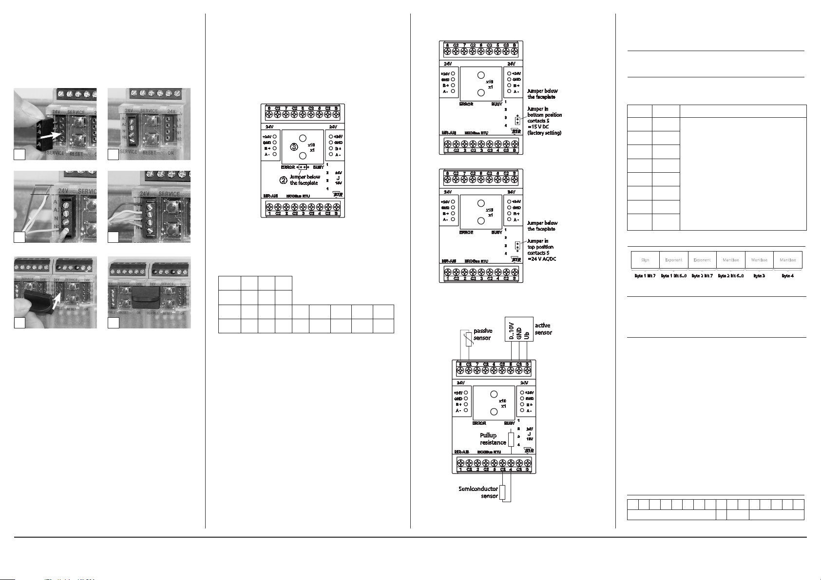
6. Mounting
Power down the equipment
Mount the module on standard rail (TH35 per IEC 60715 in
junction boxes and/or on distribution panels).
Installation
Electric ins tallat ion and device te rminat ion shal l be done by
qualified persons only, by respecting all applicable
specifications and regulations.
Plug in th e terminal bloc k for bus co nnection
21
Conne ct the ca ble for bus supply
5 mm
43
Mounting in series
65
The module can be aligned w ithout interspace. Use the jumper
plug to connect bus and supply voltage when the modules are
mounted in series.
The max imum quantity o f modules conne cted in l ine is lim ited to 15 or to a ma ximum power consumption of 2 Amps
(AC or DC ) per connecti on to the power supply. For any
simila r block of additi onal mod ules a se parate co nnection
to the power suppl y is manda tory.
7. Bit rate and Parity setting
The bit rate and parity can be set in the programming mode
when ajumper is plugged behind the front cover of the module.
This jumper is removed in normal mode. A connection to the
bus is not require d during bit rate setting.
The bit rate of the modules can be set in the following way:
1. remove the front cover of the module;
2. plug a jumper to the two middle pins of the 4 pole header
between the red and green LED ( Á);
3. set the desired parity and bit rate with the address s witches
(Â) in accordance to the chart below.
7
C2C2C2
24V 24V
+24V
GND
B+
A -
ERROR
MODBus RTU
MR-AI8
182
C2
4. switch on the supply voltage of the module; it is now permanently saving the bit rate in an EEPROM;
5. switch off the supply voltage of the module;
6. remove the jumper from the header and place the front
cover.
Switch
1 2 3
x10
C26
x10
x1
Jumper below
the faceplate
3C2
BUSY
5
S
+24V
GND
B+
A -
1
2
24V
J
3
15V
4
4
C2C2S
Parity even odd none
Switch
1 2 3 4 5 6 7 8
x1
Bitrate
1200 2400 4800 9600 19200 38400 57600 115200
(Bit/s)
If the settings differ from the settings specified in the chart the
factory setting applies.
Factor y setting: 19200 Bd Even
8. Jumper Positions for Voltage feeding of Active Sensors
7
C2C2C2
24V 24V
+24V
GND
B+
A -
ERROR
MODBus RTU
MR-AI8
182
C2
7
C2C2C2
24V 24V
+24V
GND
B+
A -
ERROR
MODBus RTU
MR-AI8
182
C2
5
S
C26
+24V
GND
x10
B+
x1
BUSY
4
3C2
5
C26
x10
x1
BUSY
4
3C2
1
2
3
4
C2C2S
1
2
3
4
C2C2S
+24V
GND
A -
S
B+
A -
Jumper below
the faceplate
Jumper in
bottom position
contacts S
=15VDC
(factory setting)
Jumper below
the faceplate
Jumper in
top position
contacts S
=24VAC/DC
9. Connection examples
active
passive
sensor
7
C2C2C2
24V 24V
+24V
GND
B+
A -
ERROR
Pullup
resistance
MODBus RTU
MR-AI8
182
C2
Semiconductor
sensor
D
sensor
Ub
0..10V
GN
5
S
C26
+24V
GND
x10
B+
x1
A -
1
BUSY
2
24V
J
3
15V
4
4
C2C2S
3C2
10. Software Description
10.1 I/O Commands
„04 (0x04) Read Input Registers“
Request:
Valid Starting Address 0 .. 15
Valid Quantity of Registers 1 .. 16 (1 to 8 inputs)
Response:
Byte Count 2 x Quantity o. R.
Registers Values Quantity o. R x 2 Bytes
Input
Register
Information
1 0-1
2 2-3
3 4-5
4 6-7
5 8-9
6 10-11
7 12-13
8 14-15
Figure 1
Sign
Byte 1 Bit 7 Byte 1 Bit 6..0 Byte 2 Bit 7 Byte 2 Bit 6..0 Byte 3 Byte 4
Configuration Registers
Input circuit and measuring range, data type and value unit and
the sensor characteristic for usual temperature sensors are set for
the 8 inputs with the 8 configuration registers.
Register contents is stored in an EEPROM.
Modbus functions:
“03 (0x03) Read Holding Registers” (max. 20 at once)
“06 (0x06) Write Single Register”
“16 (0x10) Write Multiple Registers” (max. 20 at once)
Holding Register 0-15 Offset Register is added to the measured
value in 2 succeeding registers,
(Input 1 = Register 0 - 1)
Float in both or Signed Integer 16 in the
first one, same as for measured value
Holding Register 16-23 Configuration register (EEPROM)
used to set measuring range,
data type of the measure d value
(Float / Integer 16),
unit of the measured value and the
sensor characteristic
(Input 1 = Register 16)
Holding Register 24-63 Register for interpolation charts
(EEPROM),
alternately temperature and resistance,
Float in two succeeding registers
Configuration Register for voltage or resistance measurement:
15 14 13 12 11 10 9 8 7 6 5 4 3 2 1 0
Values are supplied in 2 registers (4 Bytes).
Data type in registers can be configured
(see Registers 16 to 23):
Float value needs 2 registers (fig. 1)
signed int value is in 1st register
signed int 0 fills 2nd register
Value remains 0 until a measurement takes place
Data types composed from 2 registers start at an even
address
Exponent Exponent Mantisse Mantisse Mantisse
0 0 range number
METZ CONNECT | Im Tal 2 | 78176 Blumberg | Germany | Phone +49 7702 533-0 | Fax +49 7702 533-433
Distributed by RIA CONNECT GmbH and BTR NETCOM GmbH
Mounting instruction see www.metz-connect.com
Page 3

Continuation Software Description
Bit 15-8: occupied
Bit 7: 0 = voltage or resistance
Bit 6-5: range, defines input circuit or measuring range
0 0 voltage 0to10 V (factory setting)
0 1 voltage 0to10 V, with Pullup 2k at 5 V
1 0 resistance
1 1 occupied
Bit 4-0: number, defines presentation of value
Voltage measurement:
0 value with data type float, unit = 1V
(factory setting)
1 value with data type signed int,
unit = 10.24 V/2
2-31 reserved for other presentations
Resistance measurement:
0 value with data type float,
unit = 1 W
1 value with data type signed int,
unit = 0.1 W (max. 3.2767 kW)
2 value with data type signed int,
unit = 1 W (max. 32.767 kW)
3 value with data type signed int
unit = 10 W (max. 327.67 kW)
4 value with data type signed int
unit = 100 W (max. 3276.7 kW)
5-31 reserved for other presentations
Configuration Register for voltage or resistance measurement:
15 14 13 12 11 10 9 8 7 6 5 4 3 2 1 0
0 1 number
Bit 15-8: occupied
Bit 7: 1 = temperature with sensor characteristic
Bit 6-1: number, serves to distinguish between sensor and
measuring range
0 Sensor PT100 (-50..150 °C)
1 Sensor PT500 (-50..150 °C)
2 Sensor PT1000 (-50..150 °C)
3 Sensor NI1000-TK5000 (-50..150 °C)
4 Sensor NI1000-TK6180 (-50..150 °C)
5 Sensor BALCO 500 (-50..150 °C)
6 Sensor KTY81-110 (-50..150 °C)
7 Sensor KTY81-210 (-50..150 °C)
8 Sensor NTC-1k8 (-50..150 °C)
9 Sensor NTC-5k (-50..150 °C)
10 Sensor NTC-10k (-50..150 °C)
11 Sensor NTC-20k (-50..150 °C)
12 Sensor LM235 (-40..120 °C)
13-55 reserved for other sensors
56-61 use of interpolations chart see below
62-63 occupied
Bit 0: Data type of value
0 float, unit 1°C
1 signed int, unit 0,1°C
Configuration Register for the use of the Interpolation chart:
This chart can be used to linearize individually de fined sensor
characteristics.
15 14 13 12 11 10 9 8 7 6 5 4 3 2 1 0
0 1 7 range Int
15
= 1V/3200 = 0.3125 mV
Type
Type
Continuation Software Description Continuation Software Description Continuation Software Description
Bit 15-8: occupied
Bit 7: 1 = temperature with sensor characteristic
Bit 6-4: 7 = interpolation chart
Bit 3-2: range, defines input circuit or measuring range
0 0 voltage 0-10V
0 1 voltage 0-10V, Pullup 2k at 5V
1 0 resistance
1 1 occupied
Bit 1: selection of interpolation
0 sensor characteristic is approx. linear
1 sensor characteristic is approx.
exponential (NTC)
Bit 0: data type of value
0 float, unit 1 °C
1 signed int, unit 0.1 °C
Configurations Registers are shown above in a way to display
the meaning of the individual bit. F or the application it is more
convenient if the register conte nts is displayed as a whole, see
the following chart.
Dez Hex Measuring range Data type Unit Maximum
0 0x00 Voltage 0-10 V float 1 V
1 0x01 Voltage 0-10 V signed int 0,3125 mV 10,24 V
32 0x20 Voltage/Pullup float 1 V
33 0x21 Voltage/Pullup signed int 0,3125 mV 10,24 V
64 0x40 Resistance float 1 W
65 0x41 Resistance signed int 0,1 W 3,2767 kW
66 0x42 Resistance signed int 1 W 32,767 kW
67 0x43 Resistance signed int 10 W 327,67 kW
68 0x44 Resistance signed int 100 W 3276,7 kW
Temperature measurement with data type float.
(Value charts for sensors see annex):
128 0x80 Sensor PT100 float 1 °C (-50..150 °C)
130 0x82 Sensor PT500 float 1 °C (-50..150 °C)
132 0x84 Sensor PT1000 float 1 °C (-50..150 °C)
134 0x86 Sensor NI1000-TK5000 float 1 °C (-50..150 °C)
136 0x88 Sensor NI1000-TK6180 float 1 °C (-50..150 °C)
138 0x8A Sensor BALCO 500 float 1 °C (-50..150 °C)
140 0x8C Sensor KTY81-110 float 1 °C (-50..150 °C)
142 0x8E Sensor KTY81-210 float 1 °C (-50..150 °C)
144 0x90 Sensor NTC-1k8 float 1 °C (-50..150 °C)
146 0x92 Sensor NTC-5k float 1 °C (-50..150 °C)
148 0x94 Sensor NTC-10k float 1 °C (-50..150 °C)
150 0x96 Sensor NTC-20k float 1 °C (-50..150 °C)
152 0x98 Sensor LM235 float 1 °C (-40..120 °C)
Voltage or
resistance
Dez Hex Measuring range Data type Unit Maximum
Temperature measurement with data type signed int,
register contents is larger by 1 as above:
129 0x81 Sensor PT100 signed int 0,1 °C (-50..150 °C)
131 0x83 Sensor PT500 signed int 0,1 °C (-50..150 °C)
133 0x85 Sensor PT1000 signed int 0,1 °C (-50..150 °C)
135 0x87 Sensor NI1000-TK5000 signed int 0,1 °C (-50..150 °C)
137 0x89 Sensor NI1000-TK6180 signed int 0,1 °C (-50..150 °C)
139 0x8B Sensor BALCO 500 signed int 0,1 °C (-50..150 °C)
141 0x8D Sensor KTY81-110 signed int 0,1 °C (-50..150 °C)
143 0x8F Sensor KTY81-210 signed int 0,1 °C (-50..150 °C)
145 0x91 Sensor NTC-1k8 signed int 0,1 °C (-50..150 °C)
147 0x93 Sensor NTC-5k signed int 0,1 °C (-50..150 °C)
149 0x95 Sensor NTC-10k signed int 0,1 °C (-50..150 °C)
151 0x97 Sensor NTC-20k signed int 0,1 °C (-50..150 °C)
153 0x99 Sensor LM235 signed int 0,1 °C (-40..120 °C)
Voltage or
resistance
Temperature measurement with interpolation chart:
240 0xF0 Voltage 0-10 V float linear
241 0xF1 Voltage 0-10 V signed int linear
242 0xF2 Voltage 0-10 V float exponentiell
243 0xF3 Voltage 0-10 V signed int exponentiell
244 0xF4 Voltage/Pullup float linear
245 0xF5 Voltage/Pullup signed int linear
246 0xF6 Voltage/Pullup float exponentiell
247 0xF7 Voltage/Pullup signed int exponentiell
248 0xF8 Resistance float linear
249 0xF9 Resistance signed int linear
250 0xFA Resistance float exponentiell
251 0xFB Resistance signed int exponentiell
Register 24- 63 (0x18- 0x3F ) interpolation chart
This chart can be used to convert and linearize values for sensors
without a charac teristic alre ady defined in the device. The chart
contains up to 10 nodes of the sensor characteristic to interpolate between.
Example: conversion from resistance to temperature with temperature sensors.
Register contents is stored in the EEPROM.
The description refers to temperature sensors. Other sensors
than temperature sensors (e.g. humidity) are also possible and it
is also possible to measure voltage instead of resistance.
These proper ties can be set in the configuration register:
Measuring range: voltage
voltage, Pullup 2k at 5V (e.g. for LM235)
resistance (normal case with temperature
sensors)
Interpolation: sensor characteristic is approx. linear
sensor characteristic is approx. exponential
(für NTCs)
Data type of value: float (unit 1 °C)
signed int (unit 0.1 °C)
Modbus-Funktionen
“03 (0x03) Read Holding Registers”
“16 (0x10) Write Multiple Registers”
Node Register Register
The nodes (up to 10) are filled from the beginning of the chart,
it ends with
Temperature = resistance = 0, if less nodes ex ist.
Temperature and resistance values have to be sorted in ascen -
ding or descending order.
Data type in register s: float temperature, resistance
10.2 Bit rate setting with Modbus command
Parity and bit rate have the same value as when se tting them by
address switch.
If Parit y or Bit has the value 0, no setting or storage is carried out.
The register content is stored in the EEPROM.
“06 (0x06) Write Single Register”
Request
Valid Register Address 0x41 ( 65 )
Valid Register Value 2 Bytes
15 14 13 12 11 10 9 8 7 6 5 4 3 2 1 0
Bit 15-8: Magic-Number 0x53 = 83 as protection against
accidental writing.
The command will be further analysed only with this
number.
Bit 7-4 1 2 3
Parity even odd none
Bit 3-0 1 2 3 4 5 6 7 8
Bit rate 1200 2400 4800 9600 19200 38400 57600 115200
Response
Echo of Request
Temperature Resistance
1 24-25 26-27
2 28-29 30-31
3 32-33 34-35
4 36-37 38-39
5 40-41 42-43
6 44-45 46-47
7 48-49 50-51
8 52-53 54-55
9 56-57 58-59
10 60-61 62-63
0x53 Parity Bit rate
METZ CONNECT | Im Tal 2 | 78176 Blumberg | Germany | Phone +49 7702 533-0 | Fax +49 7702 533-433
Distributed by RIA CONNECT GmbH and BTR NETCOM GmbH
Mounting instruction see www.metz-connect.com
Page 4

Continuation Software Description
Example for a frame:
Slave address 0x12 Setting of rotary switch (18)
Function 0x06 Write Single Register
Register address Hi 0x00
Register address Lo 0x41 Bit rate and parity (65)
Register contents Hi 0x53 Magic-Number
Register contents Lo 0x15 Parity Even, 19200 Baud
All devices can be switched simultaneously with a Broadcast command (Slave address 0x00) However, it is advised not to do so as
this can c ause problems:
- Devices from other manufacturers may have under this
address a register for a different purpose that will then be
operated in the wrong way.
- There is no feedback from the individual devices.
Consequently the control cannot immediately recognize if
the command was correctly received.
It is safe r to addre ss and switch each device individually.
The device will then answer with the old settings of parity and
bit rate. Switching will take place only afterwards. However, the
answer can get lost if the bus is disturbed.
When all devices are switched; it is advised to check communication. Any function of the device providing a feedback is suit able.
If a single function is to be used being independent from the
process periphery then the function „Diagnostic“ sub-function
„Return Quer y Data“ is suitable, it returns the transferred data.
If bit rate and parity setting of a device are unknown it is possible
to address the device successively with all combinations of bit
rate and parity until the device answers. Try the most likely
combinations first. Try the lower bit rates last as they take longer.
10.3 General Commands
“08 (0x08) Diagnostics”
Subfunction “0 ( 0 x0000) Return Quer y Data”
Data Field Any
Response: Echo of Request
Subfunction “1 (0x0001) Restart Communication Option”
Data Field 0x0000 or 0xFF00
Response: Echo of Request
Action: Clears all Error Counters, Restarts node
Subfunction “4 (0x0004) Force Listen Only Mode”
Data Field 0x0000
No Response
Action: No response until Node Reset or Function
Code 08 Subcode 01
Subfunction “10 ( 0x000A) Clear Counters”
Data Field 0x0000
Response: Echo of Request
Action: Clears all Error Counters
Subfunction “11 ( 0x000B) Return Bus Message Count”
Data Field 0x0000
Response: Quantity of messages that the remote device has
detected on the communications system since its last restart,
clear counters operation, or power–up.
Subfunction “12 ( 0x000C) Return Bus Communication Error
Count”
Data Field 0x0000
Response: Quantity of errors encountered by the remote
device since its last restart, clear counters operation,
or power–up. (CRC, Length <3, Parity, Frame)
Continuation Software Description
Subfunction “13 ( 0x000D) Re turn Bus Exception Error Count”
Data Field 0x0000
Response: Quantity of MODBUS exception responses returned
by the remote device since its last restart, clear counters
operation, or power–up.
Subfunction “14 (0x000E) Return Slave Message Count”
Data Field 0x0000
Response: quantity of messages addressed to the remote
device, or broadcast, that the remote device has processed
since its last restart, clear counters operation, or power–up.
Subfunction “15 (0x000F) Return Slave No Response Count”
Data Field 0x0000
Response: Quantity of messages addressed to the remote
device for which it has returned no response (neither a normal
response nor an exception response), since its last restart, clear
counters operation, or power–up.
“43 /14 (0x2B / 0x0E) Read Device Identification”
Request
Read Device ID code: 0x01
Object ID 0x00
Response
Device ID code 0x01
Conformity level 0x01
More follows 0x00
Next object ID 0x00
Number of objects 0x03
Object ID 0x00
Object Length 0x03
Object Value “BTR”
Object ID 0x01
Object Length 0x06
Object Value “MR-AI8”
Object ID 0x02
Object Length 0x04
Object Value “V1.0”
METZ CONNECT | Im Tal 2 | 78176 Blumberg | Germany | Phone +49 7702 533-0 | Fax +49 7702 533-433
Distributed by RIA CONNECT GmbH and BTR NETCOM GmbH
Mounting instruction see www.metz-connect.com
 Loading...