

Page 1

EISC Series
Ethernet Configurable Switch Hubs
User Manual
# TD021000-0MB
Page 2

Trademarks
Contemporary Controls and CTRLink are registered trademarks of Contemporary Control Systems, Inc.
Other product names may be trademarks or registered trademarks of their respective companies.
Copyright
© Copyright 2003, by Contemporary Control Systems, Inc. All rights reserved. No part of this publication
may be reproduced, transmitted, transcribed, stored in a retrieval system, or translated into any language
or computer language, in any form or by any means, electronic, mechanical, magnetic, optical, chemical,
manual, or otherwise, without the prior written permission of:
Contemporary Control Systems, Inc. Tel: +1-630-963-7070
2431 Curtiss Street Fax: +1-630-963-0109
Downers Grove, Illinois 60515 USA E-mail: info@ccontrols.com
WWW: http://www.ccontrols.com
Contemporary Controls Ltd Tel: +44 (0)24 7641 3786
Sovereign Court Two, UWSP Fax: +44 (0)24 7641 3923
Sir William Lyons Road E-mail: info@ccontrols.co.uk
Coventry CV4 7EZ UK WWW: http://www.ccontrols.eu
Contemporary Controls GmbH Tel: +49 (0)341 520359 0
Fuggerstraße 1 B Fax: +49 (0)341 520359 16
04158 Leipzig Germany E-mail: info@ccontrols.de
WWW: http://www.ccontrols.eu
Disclaimer
Contemporary Control Systems, Inc. reserves the right to make changes in the specifications of the
product described within this manual at any time without notice and without obligation of Contemporary
Control Systems, Inc. to notify any person of such revision or change.
WARNING — This is a Class A product as defined in EN55022.
In a domestic environment this product may cause radio interference
in which case the user may be required to take adequate measures.
TD021000-0MB
2
Page 3

1
Table of Contents
1 TABLE OF CONTENTS ..................................................................................................... 3
2 INTRODUCTION................................................................................................................. 5
3 VERSIONS OF THE EISC.................................................................................................. 6
4 SPECIFICATIONS............................................................................................................... 7
4.1 Electrical ......................................................................................................................... 7
4.2 Environmental................................................................................................................. 7
4.3 Functional ....................................................................................................................... 7
4.4 RJ-45 Connector Pin Assignments ................................................................................. 8
4.5 Console Port (EIA-232) Pin Assignments ...................................................................... 8
4.6 Console Port (EIA-232) Communication Parameters..................................................... 8
4.7 Compliance ..................................................................................................................... 9
4.8 Mechanical.................................................................................................................... 10
4.8.1 16-Port Version......................................................................................................... 10
4.8.2 12-Port Version......................................................................................................... 10
5 INSTALLATION ................................................................................................................ 11
5.1 Hardware....................................................................................................................... 11
5.1.1 Mounting................................................................................................................... 11
5.1.2 Connecting to Power................................................................................................. 12
5.1.3 Connecting to the Network ....................................................................................... 14
5.1.4 Connecting to the Configuring Device ..................................................................... 15
5.1.5 Connecting to the Fault Relay................................................................................... 15
5.2 Software ........................................................................................................................ 16
6 PLUG-AND-PLAY OPERATION .................................................................................... 17
6.1 LED Indicators.............................................................................................................. 17
6.2 Switching ...................................................................................................................... 17
6.3 Data Storage.................................................................................................................. 17
6.4 Data Forwarding ........................................................................................................... 17
6.5 Flow Control ................................................................................................................. 17
6.6 Broadcast Storm Control............................................................................................... 17
TD021000-0MB
3
Page 4

7 ADVANCED OPERATION .............................................................................................. 18
7.1 General Considerations................................................................................................. 18
7.2 EISC Configurator ........................................................................................................ 18
7.2.1 Initial Configuration.................................................................................................. 19
7.2.2 Setup Options............................................................................................................ 21
7.2.3 Setting Parameters for Twisted-Pair (RJ-45) Ports................................................... 21
7.2.4 Configuring the Port Monitor ................................................................................... 22
7.2.5 Setting the Fault Relay.............................................................................................. 22
7.2.6 Advanced Features.................................................................................................... 23
7.2.7 QoS Function ............................................................................................................ 26
7.2.8 Saving Settings to EEPROM .................................................................................... 28
7.2.9 Saving and Retrieving Configuration Files............................................................... 28
7.2.10 Port Signal Strength .................................................................................................. 29
8 SERVICE............................................................................................................................. 30
8.1 Warranty ....................................................................................................................... 30
8.2 Technical Support ......................................................................................................... 30
8.3 Warranty Repair............................................................................................................ 31
8.4 Non-Warranty Repair.................................................................................................... 31
8.5 Returning Products for Repair ...................................................................................... 31
9 APPENDICES ..................................................................................................................... 32
9.1 Declaration of Conformity............................................................................................ 32
9.1.1 Applied Council Directives: ..................................................................................... 32
9.1.2 Standards to which Conformity is Declared ............................................................. 32
9.1.3 Manufacturer:............................................................................................................ 32
9.1.4 Authorized Representative:....................................................................................... 32
9.1.5 Type of equipment .................................................................................................... 32
9.2 Modbus Operation ........................................................................................................ 33
9.3 Modbus Registers.......................................................................................................... 33
9.3.1 WRITE/READ.......................................................................................................... 33
9.3.2 READ Only............................................................................................................... 36
TD021000-0MB
4
Page 5

2
Introduction
The EISC configurable switch in the CTRLink® family provides capabilities beyond those
found in standard Plug and Play (PnP) switches. Besides conventional features (autonegotiation, 10/100 Mbps data rate, half- or full-duplex operation, flow control), the EISC
has advanced features such as VLAN, trunking, Quality of Service (QoS) and a
programmable fault relay that can be connected to a supervisory system. Individual
port parameters can be configured by a Windows-based workstation. Ports can also be
monitored using the Modbus protocol, making it easy to interface the EISC with
supervisory control equipment. These features and more, make the EISC one of the
most versatile of Industrial Ethernet switches available.
The EISC boasts advanced features typically available only in high-end switches.
VLAN allows the physical network to be configured as multiple virtual local area
networks — limiting broadcast/multicast domains and improving performance.
Trunking allows ports to be associated in groups of four — each group functioning
as a high-speed backbone to another EISC configurable switch.
QoS provides message priority with any of three schemes: port-based priority, IP
packet or Diff/Serv priority (RFC 2474) or IEEE 802.1p priority.
Programmable Fault Relay provides a dry contact to a supervisory system if the
switch senses a condition such as the loss or addition of a link.
Configuration is typically done through a console port connected to a Windows-based
configuration program included with the product. Modbus protocol and register
information are also provided so the switch can be configured or monitored by a
Modbus master device. Port parameters (data rate, duplex, flow control) can be pre-set
via the console port or auto-negotiated. And a unique feature displays a dynamic signal
strength bar graph for each port.
Each port supports the PAUSE function for full-duplex links, and uses the backpressure
scheme for half-duplex segments.
The EISC is powered from wide-range, low-voltage AC or DC sources — and redundant
power connections are available for backup considerations. It comes with the ability for
either DIN-rail or panel mounting. The switch front panel features a power LED, a Fault
Relay LED and bi-color LEDs for the link status, activity, and data rate of each port.
TD021000-0MB
5
Page 6
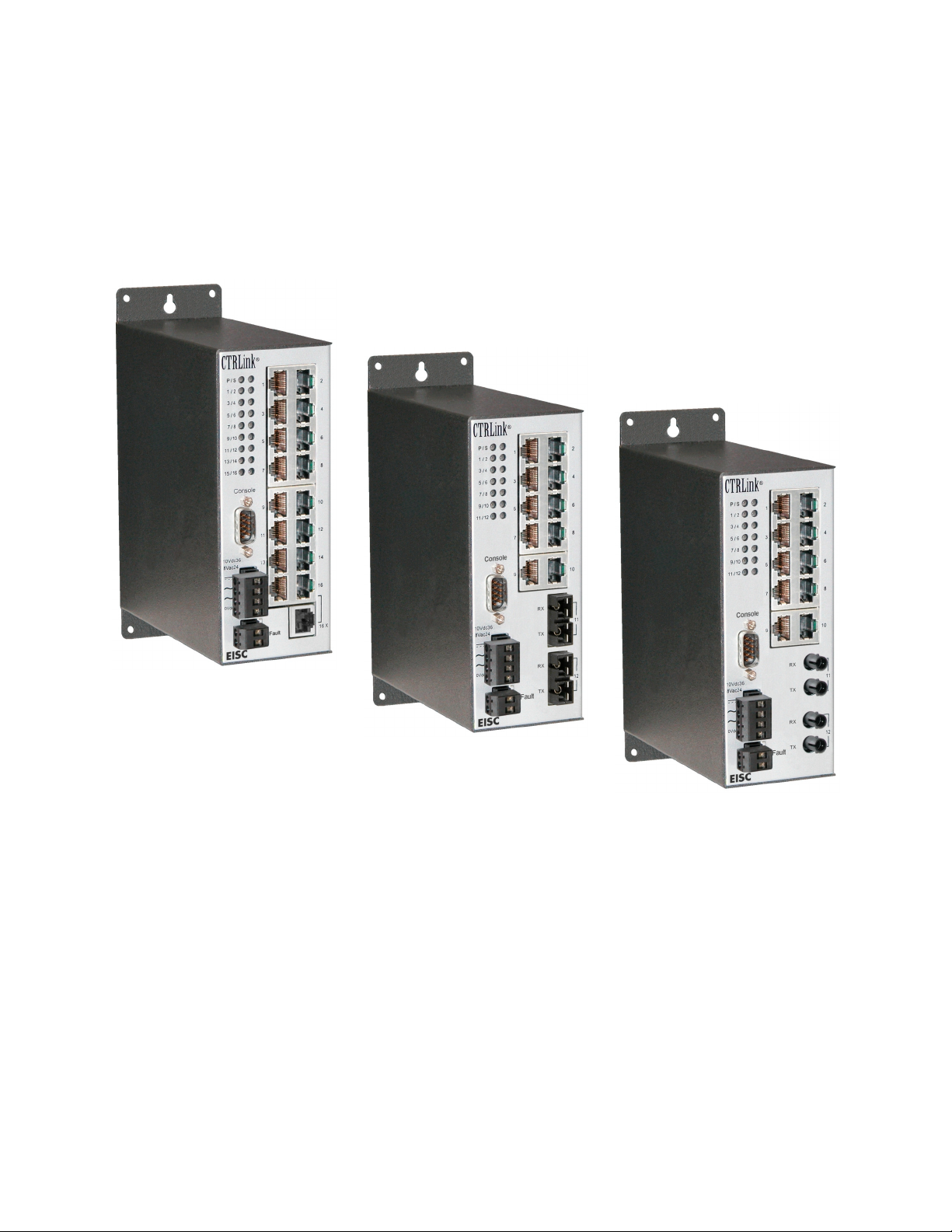
3 Versions of the EISC
EISC16-100T
EISC12-100T/FC
EISC12-100T/FT
Figure 1 — The EISC Family
TD021000-0MB
6
Page 7

4
Specifications
4.1 Electrical
Input Voltage .............................. 10-36 VDC ................................. 8-24 VAC
Input Power (max)......................10 W........................................... 10 VA
Input Frequency .........................N/A .............................................47-63 Hz
Fault Relay Contacts.................. 24 V, 500 mA (max)
4.2 Environmental
Operating Temperature..................0°C to +60°C
Storage Temperature................ –40°C to +85°C
Humidity ....................................... 10% to 95% ........................Non-Condensing
4.3 Functional
Operating Systems for
EISC Configurator : ................. Windows 98/ME/2K/XP
Aging (typical) ............................300 seconds
DC AC
Connectors : Type Function Attached Wiring
RJ-45, shielded....................... Fieldbus ........................Category 5
DB-9........................................Console......................... Null-Modem Cable
Screw, 2-terminal.................... Fault Relay.................... 16-22 AWG, solid
Screw, 4-terminal.................... Power ............................ 16-22 AWG, solid
LED Indicators : Function Color
Power............................ Green
Link/Activity ................... Green/Yellow
Status............................ Green/Yellow
Flow Control : Half-Duplex Full-Duplex
Backpressure.................................... PAUSE (IEEE 802.3x)
Transceiver Parameters : Twisted-Pair Fiber
Signaling .......................................... 10BASE-T/100BASE-TX.................. 100BASE-FX, 1300 nm
Data Rates ....................................... 10/100 Mbps..................................... 100 Mbps
Port Count ........................................ 16 or 10 ............................................0 or 2
Connectors....................................... RJ-45, shielded................................. SC or ST
Segment length (max)...................... 100 m................................................ 2 km, multimode
15 km, single mode
TD021000-0MB
7
Page 8
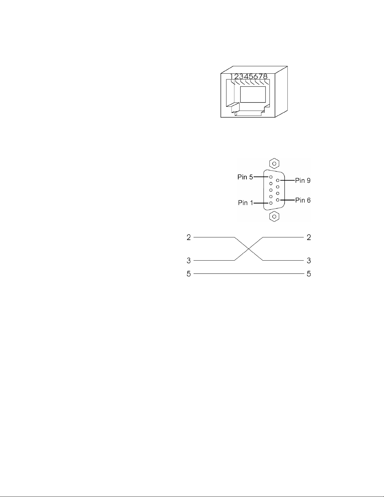
4.4
RJ-45 Connector Pin Assignments
PIN MDI-X Port 16X
1 TD+ RD+
2 TD– RD–
3 RD+ TD+
6 RD– TD–
(All other pins are unused.)
4.5 Console Port (EIA-232) Pin Assignments
PIN Signal Function
2 RXD Receive Data
3 TXD Transmit Data
5 GND Ground
(All other pins are unused.)
Null Modem Cable
4.6 Console Port (EIA-232) Communication Parameters
Baud Rate 9600 bps
Data Bits 8
Parity No Parity
Stop Bit 1
TD021000-0MB
8
Page 9
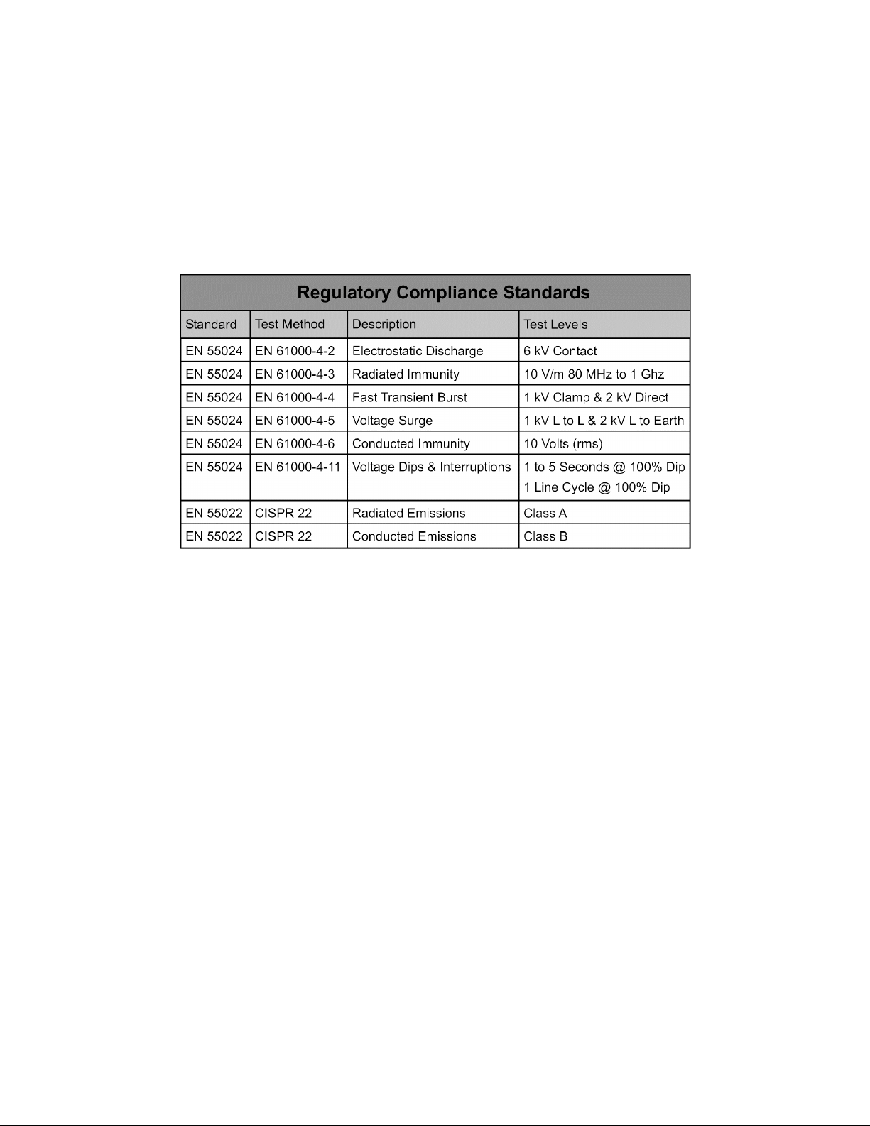
4.7
Compliance
Compatibility Compliant with ANSI/IEEE 802.3
Regulatory Compliance CE Mark
FCC Part 15 Class A
UL 508 Listed, Industrial Control Equipment
TD021000-0MB
9
Page 10
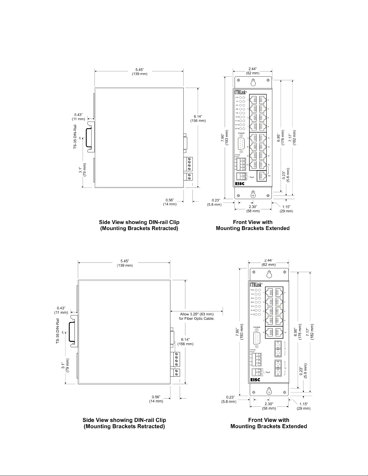
4.8
4.8.1 16-Port Version
Mechanical
4.8.2 12-Port Version Dimensions of EISC12-100T/FC (below) match those of EISC12-100T/FT.
TD021000-0MB
10
Page 11
5
Installation
5.1 Hardware
5.1.1 Mounting
The EISC is designed for mounting in an industrial enclosure or wiring closet using
either set of the provided mounting hardware listed below:
TS-35 DIN-rail Mounting
DIN-rail clip
DIN-rail clip support bracket
4-40 screws, pan-head (2)
Panel Mounting
Panel mounting bracket
4-40 screws, flat-head (4)
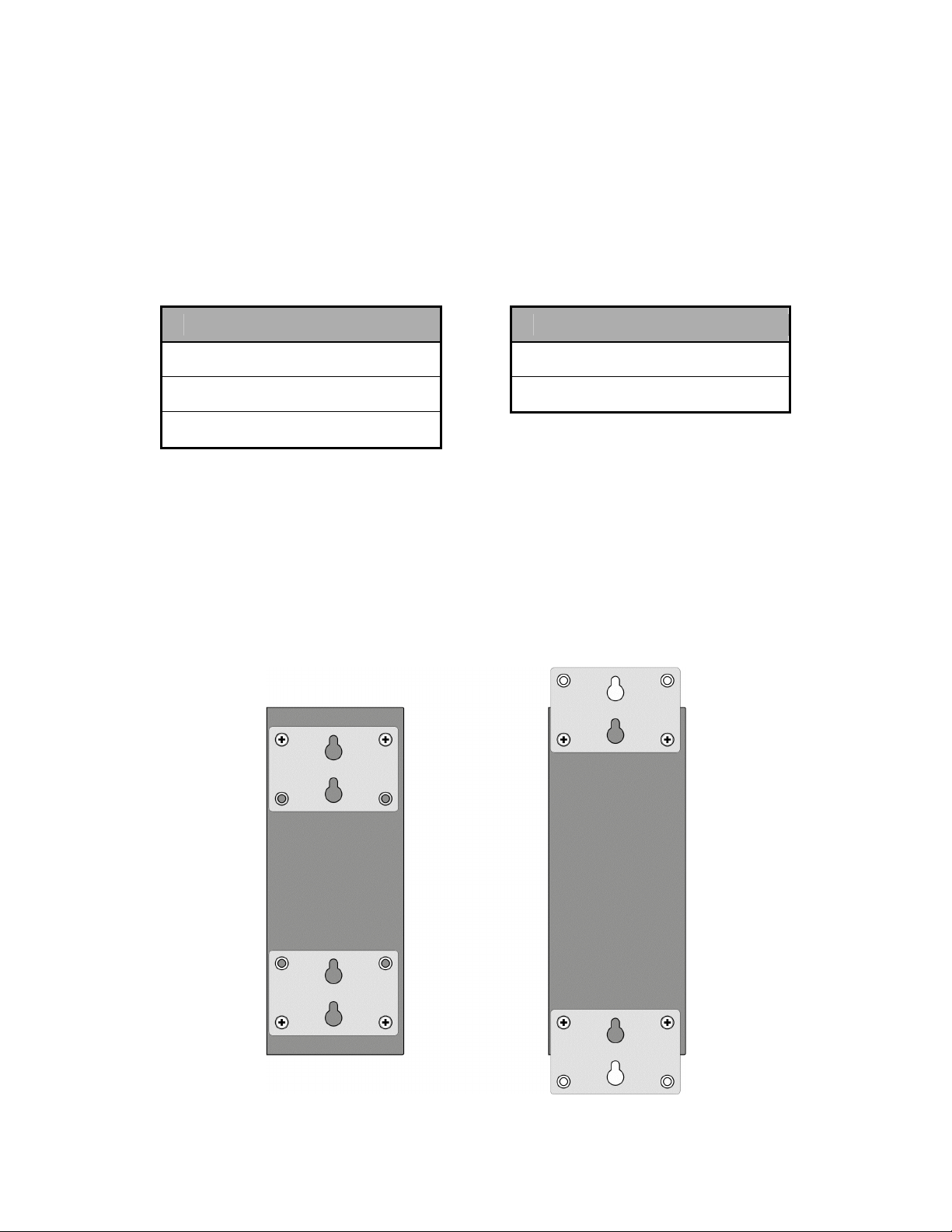
For quick snap-mounting to 35 mm DIN-rail, a reinforced DIN-rail clip is pre-attached to
the back of the EISC enclosure with two #4-40 pan-head screws. If the clip is removed,
the EISC can be panel-mounted by extending the top and bottom brackets which are
shipped in retracted position. The extended brackets can then anchor the EISC to a
wall or other flat vertical surface with two #8 pan-head screws (not provided). The left
illustration of Figure 2 shows a rear view of the EISC with brackets in retracted position.
The right illustration of Figure 2 shows the brackets extended and secured to the EISC
enclosure with the same screws used in retracted position.
Figure 2 — Using the Panel-Mounting Brackets
TD021000-0MB
11
Page 12

5.1.2
Connecting to Power
The EISC requires power via its four-pin connector. The
keyed plug is removable and is included with the switch.
The applied voltage may be either AC or DC. For power
requirements, consult the specifications. Conductors in
the range of 12–24 AWG are secured in the plug by
screw terminals. The various power options are
explained below.
NOTE: This device is intended for use with Class 2
circuits.
Figure 3 — The Power Connector
5.1.2.1 DC Powered
The EISC accepts a voltage range of 10-36 VDC and draws a value of current
commensurate with 12-watt power consumption. Power conductors should be sized
accordingly. Ground is directly connected to zero volts and the equipment chassis is
isolated from zero volts. The input connections are reverse-polarity protected.
Figure 4 — DC Powered
5.1.2.2 Redundant DC Powered
Redundant diode-isolated DC power inputs are provided so the EISC can operate
despite the loss of primary power. Both sources must provide 12 watts of power.
Figure 5 — Redundant DC Powered
TD021000-0MB
12
Page 13

5.1.2.3
AC Powered
The EISC can be powered by an AC voltage in the range of 8-24 V capable of delivering
12 VA of apparent power. Two auxiliary power supplies are available: The AI-XFMR is
for use with 120 VAC. The AI-XFMR-E is for use with 230 VAC.
Figure 6 — AC Powered
Figure 7 — AC Powered with Grounded Secondary
5.1.2.4 AC Powered with Battery Backup
The EISC can also operate in the AC mode with a backup battery providing power, if the
AC source fails. The EISC does NOT charge the battery, so separate provisions are
required for charging.
Figure 8 — AC Powered with Battery Backup
TD021000-0MB
13
Page 14

5.1.3
Connecting to the Network
When attaching network cables to the EISC, Table 1 should be considered.
Medium Signaling and
Data Rate
Copper 10BASE-T
Minimum Required
Cable
Maximum Segment
Distance
Category 3 UTP 100 m (328 ft)
10 Mbps
Copper 100BASE-TX
Category 5 UTP 100 m (328 ft)
100 Mbps
Fiber 100BASE-FX
100 Mbps
Fiber 100BASE-FX
100 Mbps
1300 nm, multimode
50/125 or 62.5/125 m
2 km (6562 ft)
(Full-Duplex only)
1300 nm, single-mode 15 km (49213 ft)
(Full-Duplex only)
Table 1 — Cabling Considerations
Observe in Table 1 that segment distance is very limited when using copper media —
regardless of the data rate. Although 10BASE-T segments can successfully use
Category 3, 4 or 5 cable, 100BASE-TX segments must use Category 5 or higher cable.
A popular choice for improved distance is fiber—which also gives good electromagnetic
noise immunity and optimum protection from lightning strikes. Considerable distance
can be achieved in multimode—and the greatest distance can be realized with singlemode fiber.
Note: The EISC allows fiber operation in full-duplex mode only.
The EISC switch supports RJ-45 field connectors. All are wired MDI-X — allowing DTE
equipment to connect via straight-through cables — except Port 16X, which is wired
MDI to permit the cascading of switches without the need of a crossover cable.
Note: Port 16 and Port 16X may NOT be used at the same time.
TD021000-0MB
14
Page 15

5.1.4
Connecting to the Configuring Device
If advanced operation is to be implemented, the Console port
must be connected via a null-modem cable to a machine that is
capable of configuring or monitoring the EISC.
5.1.5 Connecting to the Fault Relay
In advanced operation, the Fault Relay is available for use. To
monitor the Fault Relay, connect a supervisory machine to the
EISC via its two Fault Relay terminals.
Figure 9 — The
Console Port &
Fault Relay
Connector
TD021000-0MB
15
Page 16

5.2
The provided CD-ROM contains :
The software installation procedure is discussed in the readme.txt file.
Software
• The EISC Configurator Windows application and set up utility
• This User Manual
• An Ethernet Glossary
• Additional information of interest
TD021000-0MB
16
Page 17

6 Plug-and-Play Operation
6.1 LED Indicators
(All LEDs are tested each time the EISC is powered up.)
P Power
This LED glows green when power is
supplied to the EISC.
S Fault Relay Status
This LED glows green by default, but has no
function in Plug-and-Play mode.
#s Link/Activity
Each port has one of these LEDs. If a link is
established, it glows green for 100 Mbps
operation or yellow for 10 Mbps operation. It
flashes as data transfer occurs. Even LEDs
are on the right; odd LEDs are on the left.
Figure 10 — LEDs
Figure 6 shows how Ports 3 and 4 (for
example) are numbered.
6.2 Switching
The EISC uses an 8K-address look-up table augmented with 128 entries of Content
Addressable Memory to eliminate hash-collision problems. An address-hashing
algorithm is used to update the table. Addresses are aged in about 300 seconds.
Illegal frames that are always discarded include bad CRC packets, runt packets (less
than 64 bytes) and oversized packets (greater than 1536 bytes).
6.3 Data Storage
Data storage buffer for Ethernet packets consists of 512 kB.
6.4 Data Forwarding
An entire Ethernet packet must be received before forwarding occurs. The EISC wire
speed forwarding rate (non-blocking) is 148,800 packets per second at 100 Mbps and
includes a special design to resolve head-of-line-blocking problems.
6.5 Flow Control
Each twisted-pair port automatically negotiates flow control and half- or full-duplex
operation. In full-duplex mode, the IEEE 802.3x PAUSE function is supported. In halfduplex mode, the backpressure method is used. To prevent the connected repeater
from being partitioned due to excessive collisions, backpressure allows the forwarding
of one packet after 48 collisions.
6.6 Broadcast Storm Control
Using a storm-control counter, each port will pass 64 continuous broadcast packets
before dropping extra ones. The counter will reset every 800 ms or after receiving a
non-broadcast packet.
TD021000-0MB
17
Page 18

7
Advanced Operation
7.1 General Considerations
Configuration is accomplished while the EISC is connected to a suitable device — either
a computer running the provided EISC Configurator Windows application or a Modbuscapable user device. For monitoring and configuring the EISC with Modbus, refer to
Section 9.2.
7.2 EISC Configurator
When first launched, the EISC Configurator appears as in Figure 11 with no parameters
configured and Setup and Signal Strength menus not available (dimmed). Configuring
the switch is discussed on the following pages. The portions of Figure 11 outlined in red
will be unavailable (dimmed) for models EISC12-100T/FC and EISC12-100T/FT.
Figure 11 — The EISC Configurator
TD021000-0MB
18
Page 19

7.2.1
Initial Configuration
With a null-modem cable connecting the EISC to a suitable computer, launch the EISC
Configurator, select a COM port and then click the “Connect” button. If the EISC
Configurator cannot connect to the EISC, the error message of Figure 12 may appear.
If this should happen, check that a proper null-modem cable is used for the connection
and that suitable power is applied to the EISC. If the error in Figure 13 appears, a new
COM port must be chosen.
Figure 12 — Error Connecting to EISC Figure 13 — COMPORT Error
Once the Configurator has connected to the EISC, the display of Figure 14 should
appear — with the Setup and Signal Strength menus now available. The File menu
will remain dimmed so long as the EISC is in communication with the EISC Configurator.
The portions of Figure 14 shown outlined in red will be unavailable (dimmed) for models
EISC12-100T/FC and EISC12-100T/FT.
TD021000-0MB
19
Page 20

y
Link condition is
indicated by color:
green = active
(100 Mbps)
yellow = active
(10 Mbps)
Used to connect
to console port
Displays
configuration
of each port
If port monitoring is
enabled, a port fault
condition will be
displayed until it is
cleared by the
“Clear Faults” button.
Port Monitoring
can be disabled.
Displays
state of
Fault
Rela
Fault Relay
status is
indicated
by color:
green = okay
yellow = fault.
If not dim,
Trunk Group
is enabled.
LED will glow
if trunk is
intact.
Active only
if relay is
configured
for manual
reset.
Clears all
fault
indicators
Figure 14 — EISC Ready for Configuration
TD021000-0MB
20
Page 21

7.2.2
Setup Options
The Setup pull-down menu offers the options
shown in Figure 15:
Set the Individual Port Behaviors
Define How the Fault Relay Responds
Set Trunking, VLAN and Flow Control
Set the QoS Options
Lock in Your Settings
Restore All Default Settings
Set the Modbus Slave Address
Figure 15 — Setup Options
The first order of business is to configure the port parameters.
7.2.3 Setting Parameters for Twisted-Pair (RJ-45) Ports
When the “Port Parameters” option is chosen, the display shown in Figure 16 appears.
By default, each RJ45 port is set to auto-negotiate with full-duplex flow control. The
portion of Figure 16 outlined in red will be dimmed for models EISC12-100T/FC and
EISC12-100T/FT. Fiber ports are permanently set to 100 Mbps and full-duplex.
Figure 16 — Port Parameters
Each RJ-45 port has a pull-down menu so the port can be set
with any of the parameters shown in Figure 17. If either Half
Duplex option is chosen, the Full Duplex Flow Control check box
will be dimmed. In this case, half-duplex flow control will be set
by the Backpressure Flow Control option under Advanced
Features. Otherwise, full-duplex flow control may be engaged or
disengaged for each RJ-45 port on an individual basis.
TD021000-0MB
21
Figure 17 —
RJ45 Port Options
Page 22

7.2.4
Configuring the Port Monitor
Figure 18 displays the features of the Port Monitor which can watch each port for a fault
condition specific to that port. The portion of Figure 18 shown outlined in red will be
unavailable (dimmed) for models EISC12-100T/FC and EISC12-100T/FT.
Figure 18 — The Port Monitor
Each port can be monitored for one of three options shown in
Figure 19. The default setting is for the Port Monitor to “Ignore”
the situation of a given port. If the user chooses the “No Link”
option, the monitor will report a fault if proper link pulses are not
received by the given port. Selecting the “Link Present” option
provides a means for alerting the network administrator if an
unauthorized link has been established.
Figure 19 —
Port Monitor Options
7.2.5 Setting the Fault Relay
At the bottom of the Port Monitor window shown in Figure 18 there are four Fault Relay
settings: “Port Monitoring” must be enabled for the relay to function. The user may
choose for the relay to either “make” or “break” on fault. Following power up, the relay
action can be delayed for up to 999 seconds. Finally, the user can elect to reset the
relay manually or have it reset automatically once the fault clears.
For convenience, Port Monitoring can also be controlled from the bottom of the main
Configurator panel where the relay state is reported and where faults can be cleared
and the relay manually reset (if enabled).
TD021000-0MB
22
Page 23

7.2.6
7.2.6.1 Port Trunking
Advanced Features
Port Trunking allows four ports to be grouped together with the resulting group behaving
as a single logical link. Each trunk is constructed of four fixed physical ports — with one
status “LED” for each Trunk Group shown in the main screen of the configuration
program. This “LED” will glow solid green when the trunk is enabled and operating
properly. If the link for any physical port of a trunk fails, then all of the physical ports of
the trunk are treated as defective and the trunk “LED” will no longer glow — thus
indicating a fault condition.
Model EISC16-100T supports four trunks and the trunk selection in its Advanced
Settings display will appear as shown in Figure 20.
Figure 20 — Trunk Options :
EISC16-100T
Figure 21 — Trunk Options :
EISC12-100T/FC & EISC12-100T/FT
Models EISC12-100T/FC and EISC12-100T/FT support two trunks and the trunk options
in their Advanced Settings display will appear as shown in Figure 21.
To keep frames in order, packets with identical source/destination MAC addresses are
sent over the same trunk path — but the reverse path may follow a different link. A
hash algorithm is used to balance the load between links in a trunk.
TD021000-0MB
23
Page 24

7.2.6.2 Port-Based VLAN Function
In the Advanced Settings window, port-based (also called Layer 1) VLAN functionality
can be selected. The number of VLANs available varies with the EISC model.
Model ESIC16-100T supports 14 or 15 VLANs as shown in Figure 22. If 14 VLANs are
chosen, each of Ports 1–14 becomes an independent VLAN. All 14 VLANs can
communicate with Ports 15 and 16 which are termed common ports. If 15 VLANs are
defined, Port 15 ceases to act as a common port and acts, instead, as one of the
independent VLAN ports — and then Ports 1–15 can communicate with the only
remaining common port, Port 16.
Figure 22 — VLAN Options :
EISC16-100T
Figure 23 — VLAN Options
EISC12-100T/FC & EISC12-100T/FT
Figure 23 depicts the VLAN options for models EISC12-100T/FC and EISC12-100T/FT.
As shown, each 12-port model can support 11 VLANS, with Port 12 (one of the fiber
optic ports) performing the function of the common port.
When VLANs are enabled, a frame received from a VLAN port will only be forwarded to
the common port[s]. If the destination port belongs to another VLAN, the frame will be
discarded. If the source of the frame is a common port, then the frame can be
forwarded to any destination. This topology allows networks to share a server or router
via the common port[s], but use different VLANs for security or performance reasons.
Figure 24 — VLANs with a Common Server
TD021000-0MB
24
Page 25

7.2.6.3
7.2.3.6.1 Broadcast Storm Control
Global Features
(applying to ALL ports)
The EISC can enable or disable broadcast storm filtering. When enabled, each port will
drop broadcast packets — those with a Destination MAC ID of FF FF FF FF FF FF — after
receiving 64 continuous broadcast packets. The counter will be reset to 0 every 800 ms
or on receiving a packet with a Destination MAC ID other than FF FF FF FF FF FF.
Figure 25 — Global Features
7.2.3.6.2 Backpressure Flow Control
Backpressure flow control is applied globally — affecting all half-duplex ports or none. If
this feature is disabled, the destination of the incoming packet is checked and, if found
to be congested, the packet is discarded to avoid blocking the packet stream.
TD021000-0MB
25
Page 26

r
7.2.7 QoS Function
The EISC can recognize QoS priority information for incoming frames. With this
information, each affected frame is assigned an appropriate level of priority.
7.2.7.1 Priority Queues.
The EISC has two
queues, one for High-priority frames and one for
Low-priority frames. The queue service rate uses
the Weighted Round Robin algorithm where the
weight ratio of high-to-low priority queuing can
be 2:1, 4:1, 8:1 or "Always high priority first". For
example, if the “4:1” option is selected, the Highpriority queue is serviced 4 times as often as the
Low-priority queue.
7.2.7.2 Auto-off Flow Control.
If a port receives a high-priority frame, flow control
Figure 26 — Round Robin Priority
can be disabled for 1–2 seconds and automatically re-enabled after no priority frames
have been received for a period of 1–2 seconds — when this option is enabled.
The EISC offers three
kinds of QoS priority:
• DiffServ Priority
(IP Packet);
• 802.1p/Q Tagging;
• Port-Based Priority.
Figure 27 — Other QoS Settings
7.2.7.3 Port-Based Priority.
When this is
applied, any frame received via a high priority
port is given high priority. In the EISC, Ports 1
and 2 can be designated high priority ports — o
Ports 1–4 can be assigned — or all of Ports 1–8
can be given high-priority. Whatever port group
is defined, frames received via this group are
buffered into the High-priority queue while
frames from all other ports are relegated to the
Low-priority queue.
Figure 28 — Port Based Prority
TD021000-0MB
26
Page 27

7.2.7.4 ToS/DiffServ Priority.
IP protocol frames include in their network headers
an 8-bit Type of Service (ToS) field for packet prioritization. The first three of these bits
specify 8 levels of priority. The next three bits provide the QoS refinement known as
Differentiated Services (DiffServ or DS) which efficiently manages traffic by categorizing
packets into classes to apply rules for packet delay and discarding. The two remaining
bits of the ToS octet are not yet defined.
Differentiated Services can offer:
• Expedited Forwarding (EF) for low loss, low latency, low jitter and assured bandwidth;
• Assured Forwarding (AF) specifies drop precedence to apply when traffic becomes congested;
• Best Effort, which uses any bandwidth not allocated to EF and AF.
DiffServ allows nodes that are either ignorant of or incapable of DS coding to use the
network with best-effort forwarding by using the default value in the DS field.
If ToS/DiffServ priority is applied, the EISC can read this information (defined in
RFC2474) from the DS field byte. Recommended codepoints are defined in RFC2597
to distinguish traffic by different service classes. The EISC can read this 6-bit value —
in either IPv4 or IPv6 frames — and can then identify the incoming packet priority as
shown in Table 2:
DS Field Value Priority Per Hop Behavior
101110 EF (Expected Forwarding)
001010, 010010, 011010, 100010 AF (Assured Forwarding)
110000, 111000
All others values Low Uncharacterized
High
Network Control
Table 2 — DiffServ Packet Priority
7.2.7.5 802.1p/Q Priority Tagging.
When this EISC option is enabled, VLAN
“tagged” frame priority is recognized. In the data link header, the 802.1p supplement
provides priority coding which was never specified in the 802.1Q VLAN-tagging
standard. Within the VLAN tag space, a 3-bit code is applied so that “tagged” frames
can specify priority. Values 4–7 are assigned to the EISC High-priority queue and
values 0–3 to the Low-priority queue. Switches and other network equipment, can set
these priority bits.
The IEEE suggests a priority scheme, but does not mandate a definition. This method
represents a simple, best-effort Layer 2 prioritization for network adapters and switches
— requiring no bandwidth reservation.
Note: Since the data link header is only read at the switch level, networks which have
routers cannot use this method unless special mapping is implemented.
TD021000-0MB
27
Page 28

A
A
7.2.8 Saving Settings to EEPROM
fter configuring the EISC, the new parameters
will apply, but only so long as the switch has
power. If it is desired to retain settings in EEPROM
for use after a power interruption, choose the
“Save Settings to Non-Volatile Memory” option in
the Setup pull-down menu. The message
shown in Figure 29 confirms the action.
Figure 29 — Save Settings to Switch
7.2.9 Saving and Retrieving Configuration Files
To save the EISC configuration to a file for later use, it
is first necessary to disconnect the EISC from the
EISC Configurator. Once this has been done, choose
the “Save As …” option in the File pull-down menu.
standard “Save As” pop-up window will then allow the
user to create a file name for the saved file. The file
type will be *.eic.
Figure 30 —
Saving or Opening a File
A saved configuration file can be retrieved and
downloaded to the EISC. Once this is done, the
retrieved parameters are implemented automatically.
Retrieve the file by choosing the “Open…” option
under the File pull-down menu. Once the file is
opened, the title bar of the EISC Configurator
window will report the file name and the Setup
pull-down menu will become active. At this point,
the retrieved file can be modified before it is
downloaded to the EISC. Modifiable options are
indicated as active in the Setup pull-down menu.
Figure 31 — Retrieved File
Note: A retrieved file will NOT be retained in the switch EEPROM unless the user chooses
the “Save Settings to Non-Volatile Memory” option in the Setup pull-down menu.
TD021000-0MB
28
Page 29

(
7.2.10
Port Signal Strength
Only for 100 Mbps RJ-45 ports)
The EISC can display the signal strength received at its RJ-45 ports in four graduated
steps. Each port display can thereby indicate the robustness of its communication
channel. Although an attached device could cause problems, the usual concern with
signal strength is the nature of
attached twisted-pair cable.
A port label will only display as
active if it is receiving proper
Link Pulses. If a port is not
attached to a working partner,
its label will be dim and its bar
graph completely gray.
To read the display properly,
the user must have knowledge
of the cabling attached to the
EISC. As more cable length is
used to connect an EISC port
to a remote device, weaker
signal strength will be seen.
As the 100-m cable length limit
is approached, the smallest
signal strength step will be
displayed in red (as with Port
11 in Figure 32). A disparity
between two ports does not
necessarily imply a problem
with the weaker one; the two
ports may simply be attached
to different lengths of cable.
Figure 32 — Twisted-Pair Signal Strength
Example: In Figure 32, a comparison of Port 10 and Port 11 should only be interpreted
as problematic if the segment lengths for Ports 10 and 11 are approximately equal. On
the other hand, if Port 10 has only 15 m of attached cable while Port 11 has 85 m of
attached cable, the example display would be normal.
Note: There is no requirement for all segments of a trunk to be equal in length. Thus,
Ports 9–12 in Figure 32, could be displaying a properly functioning trunk.
Note for 12-port models: The signal strength display applies only to Ports 1
–8. For
Ports 9–12 the bar graph will be completely blank — even if the port is working.
Although there is no signal strength indication for Ports 9–12, the status of these ports
can be determined by simply observing the port label . If the label is not dimmed, the
port is active. But if the label is dimmed, the port is not in use.
TD021000-0MB
29
Page 30

8
Service
8.1 Warranty
Contemporary Controls (CC) warrants its product to the original purchaser for one year
from the product’s shipping date. If a CC product fails to operate in compliance with its
specification during this period, CC will, at its option, repair or replace the product at no
charge. The customer is, however, responsible for shipping the product; CC assumes
no responsibility for the product until it is received. This warranty does not cover repair
of products that have been damaged by abuse, accident, disaster, misuse, or incorrect
installation.
CC’s limited warranty covers products only as delivered. User modification may void the
warranty if the product is damaged during installation of the modifications, in which case
this warranty does not cover repair or replacement.
This warranty in no way warrants suitability of the product for any specific application.
IN NO EVENT WILL CC BE LIABLE FOR ANY DAMAGES INCLUDING LOST
PROFITS, LOST SAVINGS, OR OTHER INCIDENTAL OR CONSEQUENTIAL
DAMAGES ARISING OUT OF THE USE OR INABILITY TO USE THE PRODUCT
EVEN IF CC HAS BEEN ADVISED OF THE POSSIBILITY OF SUCH DAMAGES, OR
FOR ANY CLAIM BY ANY PARTY OTHER THAN THE PURCHASER.
THE ABOVE WARRANTY IS IN LIEU OF ANY AND ALL OTHER WARRANTIES,
EXPRESSED OR IMPLIED OR STATUTORY, INCLUDING THE WARRANTIES OF
MERCHANTABILITY, FITNESS FOR PARTICULAR PURPOSE OR USE, TITLE AND
NONINFRINGEMENT.
Repair or replacement as provided above shall be the purchaser's sole and exclusive
remedy and CC's exclusive liability for any breach of warranty.
8.2 Technical Support
Technical support is available each weekday (except holidays) during the office hours
listed below. Outside these hours, voice-mail messages can be left in our mailbox after
contacting the main phone number. Requests can also be submitted by fax or by e-mail
to the numbers listed below, but please leave a detailed description of the problem. We
will contact you the next business day by the method requested by the customer. If the
problem cannot be resolved by technical support, the customer will be given an RMA
number in order that the product may be returned to CC for repair.
Support Option Contemporary Controls (USA) Contemporary Controls Ltd (UK)
Office Hours
Voice
Fax
Email
Web Site
8:00 a.m. — 5:00 p.m. Central time 8:00 a.m. — 5:00 p.m. United Kingdom time
+1-630-963-7070 +44 (0)24 7641 3786
+1-630-963-0109 +44 (0)24 7641 3923
techsupport@ccontrols.com support@ccontrols.co.uk
www.ccontrols.com www.ccontrols.co.uk
TD021000-0MB
30
Page 31

8.3
Warranty Repair
Products under warranty that were not subjected to misuse or abuse will be repaired at
no charge to the customer. The customer, however, pays for shipping the product back
to CC while CC pays for the return shipment to the customer. CC normally ships
ground. International shipments may take longer. If the product has been determined to
be misused or abused, CC will provide the customer with a quotation for repair. No
work will be done without customer approval.
8.4 Non-Warranty Repair
CC provides a repair service for all its products. Repair charges are based upon a fixed
fee basis depending upon the complexity of the product. Therefore, Customer Service
can provide a quotation on the repair cost at the time a Returned Material Authorization
(RMA) is requested. Customers pay the cost of shipping the defective product to CC
and will be invoiced for the return shipment to their facility. No repair will be performed
without customer approval. If a product is determined to be unrepairable, the customer
will be asked if the product can be replaced with a refurbished product (assuming one is
available). Under no circumstances will CC replace a defective product without
customer approval. Allow ten working days for repairs.
8.5 Returning Products for Repair
To schedule service for a product, please call CC Customer Service support directly at
+1-630-963-7070 (U.S.) or +44 (0)24 7641 3786 (U.K.). Have the product model and
serial number available, along with a description of the problem. A Customer Service
representative will record the appropriate information and issue, via fax, an RMA
number—a code number by which we track the product while it is being processed.
Once you have received the RMA number, follow the instructions of the Customer
Service support representative and return the product to us, freight prepaid, with the
RMA number clearly marked on the exterior of the package. If possible, reuse the
original shipping containers and packaging. In any event, be sure you follow good ESDcontrol practices when handling the product, and ensure that antistatic bags and
packing materials with adequate padding and shock-absorbing properties are used. CC
is not responsible for any damage incurred from improper packaging. Shipments
should be insured for your protection.
Ship the product, freight prepaid, to the location from which it was purchased:
Contemporary Control Systems, Inc.
2431 Curtiss Street
Downers Grove, IL 60515
U.S.A.
Contemporary Controls Ltd
Sovereign Court Two, UWSP
Sir William Lyons Rd.
Coventry CV4 7EZ
U.K.
TD021000-0MB
31
Page 32

9
Appendices
9.1 Declaration of Conformity
9.1.1 Applied Council Directives:
Electromagnetic Compatibility Directive, 89/336/EEC Council Directive as amended by
Council Directive 92/31/EEC & Council Directive 93/68/EEC
General Product Safety Directive 92/59/EEC
9.1.2 Standards to which Conformity is Declared
EN 55022:1995 CISPR22: 1993, Class A, Limits and Methods of Measurement of Radio
Disturbance Characteristics of Information Technology Equipment
EN 55024:1998, Information Technology Equipment — Immunity Characteristics —
Limits and Methods of Measurement
9.1.3 Manufacturer:
Contemporary Control Systems, Inc.
2431 Curtiss Street
Downers Grove, IL 60515 USA
9.1.4 Authorized Representative:
Contemporary Controls Ltd
Sovereign Court Two, UWSP
Sir William Lyons Road
Coventry CV4 7EZ
UNITED KINGDOM
9.1.5 Type of equipment
— Ethernet configurable switching hub.
For regulatory compliance, refer to Section 4.7
Manufacturer’s Declaration: I, the undersigned, hereby declare that the product
specified above conform to the listed directives and standards.
George M. Thomas, President January 1, 2004
TD021000-0MB
32
Page 33

9.2
Modbus Operation
For Modbus operation, the EIA-232 parameters must be set as follows :
Baud Rate = 9600 bps, Data Bits = 8, Stop Bit = 1, No Parity
9.3 Modbus Registers
9.3.1 WRITE/READ
40001-40016: Port Settings: Auto-negotiation or set speed/duplex per port
Bit 0 – Auto-negotiation (enabled = 1, disabled = 0) – default = 1
Bit 1 – 10Mbps(0) or 100Mbps (1)
Bit 2 – Half duplex (0) or full duplex (1)
Bit 3 – Enable full duplex flow control (enabled = 1, disabled = 0) – default = 1
40001: Port Settings port 1
40002: Port Settings port 2
40003: Port Settings port 3
40004: Port Settings port 4
40005: Port Settings port 5
40006: Port Settings port 6
40007: Port Settings port 7
40008: Port Settings port 8
40009: Port Settings port 9
40010: Port Settings port 10
40011: Port Settings port 11
40012: Port Settings port 12
40013: Port Settings port 13
40014: Port Settings port 14
40015: Port Settings port 15
40016: Port Settings port 16
TD021000-0MB
33
Page 34

[40017-40128: Port Settings port 17 – port 128 reserved]
40129: Reserved for future use
40130: Reserved for future use
40131: Reserved for future use
40132: Relay Setting1
Bit 0: Relay Active State (0- Disengaged, 1-Engaged) default = 0
Bit 1: Relay Reset Method (0 – Self-recovering, 1- Reset by user) default = 0
Bit 2: Monitoring Status (0 – Disabled, 1 – Enabled) default = 1
Bit 3: Clear Faults (1 = Clear)
Bit 4: Reset Relay (1 = Reset)
40133: Relay Activation Time after power up (in secs)
40134: Port monitor setting1 (ports 1-8): Energize relay upon matching condition
00 – Don’t care
01 – Link_Lost
10 – Link_Up
11 – Don’t care
Port8 Port7 Port6 Port5 Port4 Port3 Port2 Port1
Bit 15,14 13,12 11,10 9,8 7,6 5,4 3,2 1,0
40135: Port monitor setting2 (ports 9-16): Energize relay upon matching condition
00 – Don’t care
01 – Link_Lost
10 – Link_Up
11 – Don’t care
Port16 Port15 Port14 Port13 Port12 Port11 Port10 Port9
Bit 15,14 13,12 11,10 9,8 7,6 5,4 3,2 1,0
40136-40149: (reserved for 128 port switch)
TD021000-0MB
34
Page 35

40150: QOS Settings (all disabled by default)
Bit 6: Enable Flow Control Automatic disable
Bit 5: Enable DiffServ Priority QOS
Bit 4-3: Enable Port based Priority QOS
00 – disable(default)
01 – Ports 0&1 high priority
10 – Ports 0-3 high priority
11 – Ports 0-7 high priority
Bit 2-1: Enable Weighted Round Robin Priority
It is the service rate ratio of High-Priority queue to Low-Pri Queue
11 – always high priority queue first(default)
10 – 8:1
01 – 4:1
00 – 2:1
Bit 0: Enable 802.1p VLAN Tag Priority based QOS
40151: Misc. Feature Settings
(all disabled by default, except for backpressure and Broadcast Storm Control)
Bit 7: Enable Backpressure (0=disabled, 1=enabled) – default:enabled
Bit 6: VLAN Type (0 = 14 VLANS, 1 = 15 VLANS)
Bit 5: Enable VLAN
Bits 4-1: Enable Port Trunking and select trunks (0-3)
Bit 4: 1 – Enable Port Trunk 3
Bit 3: 1 – Enable Port Trunk 2
Bit 2: 1 – Enable Port Trunk 1
Bit 1: 1 – Enable Port Trunk 0
Bit 0: Enable Broadcast Storm control – default: enabled.
40152: Modbus Slave Address
Modbus Address of the switch
40153: Offline Mode (1 = Offline & MAC in Reset)
40154: Write EEPROM with current switch settings (1= write)
40155: Write Switch with default settings (1 = write)
TD021000-0MB
35
Page 36

9.3.2
READ Only
41001-41016: Port 1-16 status:
Bit 0: Duplex (0 = half, 1= full)
Bit 1: Speed (0 = 10Mbps, 1 = 100Mbps)
Bit 2: Link (0 = no link, 1=link active)
Bit 3-6: Reserved
Bit 7: 1 = Relay Activation due to fault on this port
41001: Port status port 1
41002: Port status port 2
41003: Port status port 3
41004: Port status port 4
41005: Port status port 5
41006: Port status port 6
41007: Port status port 7
41008: Port status port 8
41009: Port status port 9
41010: Port status port 10
41011: Port status port 11
41012: Port status port 12
41013: Port status port 13
41014: Port status port 14
41015: Port status port 15
41016: Port status port 16
[41017-41128: Port status port 17- port 128 reserved]
41129: Trunk Status:
Bit 0: Trunk 0 status (0 = Disabled, 1 = Enabled)
Bit 1: Trunk 1 status (0 = Disabled, 1 = Enabled)
Bit 2: Trunk 2 status (0 = Disabled, 1 = Enabled)
Bit 3: Trunk 3 status (0 = Disabled, 1 = Enabled)
41130: MISC Status:
Bit 0: Relay Status (0= Relay Active, 1= Relay Inactive)
Active state could be engaged/disengaged, depending on the value set in
register 40132, bit 0.
41134: Firmware Version
TD021000-0MB
36
 Loading...