

Page 1
EIDX_M Series
A Line of Managed Ethernet Switching Hubs
INSTALLATION GUIDE
INTRODUCTION
The EIDX_M Series of managed Industrial Ethernet switches provides the user
with a sophisticated instrument with several advanced features for the
discriminating network professional. Each of the 8 models in the series operates
in extended temperatures while offering a choice of mounting, port count, media
and support.
To optimise speed and throughput, some functions are automatically negotiated:
Each twisted-pair port automatically optimises its data rate to 10 Mbps or 100
Mbps. The data rate of fibre ports is fixed at 100 Mbps.
Each port negotiates flow control — supporting the PAUSE fun ction for fullduplex links, and using the backpressure scheme for half-duplex segments.
All units offer non-blocking wire-speed operation with a maximum data rate of
148,810 frames per second for 100 Mbps Ethernet on all ports at full duplex.
Copper ports are wired MDI-X (internal crossover) for attaching NICs via straightthrough cables.
All units support SNMP and offer these advanced f e a tures:
RapidRing™ high-speed redundancy (link loss recovery under 300 ms)
VLANs to limit broadcast/multicast domains and improve performance
Trunking to allow high-bandwidth redundant backbones
QoS message priority for either port-based or MAC-based priority
Programmable fault relay to indicate the loss or addition of a link
Auto-MDIX for all copper ports enabled/ disabled by software control
All units operate from low-voltage AC/DC sources — and redundant power
connections are available for backup considerations. They come with the ability
for either DIN rail or panel mounting. The front panel features LED indicators
for power and CPU status — and link status, activity and data rate of each port.
Page 2
SPECIFICATIONS
Electrical (for 24-port models)
INPUT DC AC
Voltage
Power (max): 14 W 35 VA
±5%: 24 VDC 24 VAC
Regulatory Compliance
CE Mark; CFR 47, Part 15 Class A
UL508 Listed
(intended for use with Class 2 circuits)
Industrial Control Equipment
Functional
Temperature
Operating: –40°C to +75°C
Storage: –40°C to +85°C
Shipping Weight
2 lbs. (.9 kg)
Warning: This is a Class A product. In a domestic environment the product may cause
radio interference in which case the user may be required to take adequate measures.
Compliance: ANSI/IEEE 802.3
Data Rate: 10 Mbps and 100 Mbps
Signalling: 10BASE-T, 100BASE-TX,
100BASE-FX
LED Indicators
Power green
Status red/green
Ports green/yellow
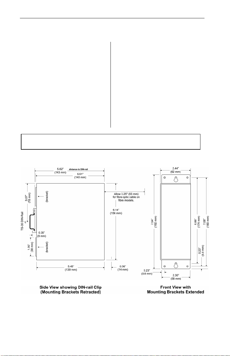
Mechanical
Figure 1 — EIDX Dimensions
TD071105-0IA
2
Page 3
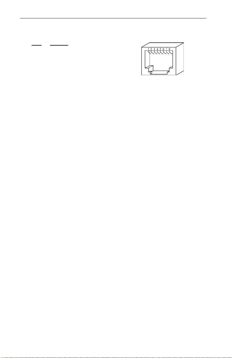
Figure 2 — RJ-45 Connector
RJ-45 Connector Pin Assignments
PIN MDI-X
1 TD+
2 TD–
3 RD+
4 unused
5 unused
6 RD–
7 unused
8 unused
TD071105-0IA
3
Page 4

DIN rail clip
Panel mounting bracke t
M3x5 screws, flat-head (4)
M3x5 screws, flat-head (4)
INSTALLATION
Mounting
The EIDX is designed for mounting in an industrial enclosure or wiring closet
using either set of the provided mounting hardware listed below:
TS-35 DIN Rail Mounting
For quick snap-mounting to 35 mm DIN rail, a reinforced DIN rail clip is preattached to the back of the EIDX enclosure with four M3x5 flat-head screws. If
the clip is removed, the EIDX can be panel-mounted by extending the top and
bottom brackets which are shipped in retracted position. The extended brackets
can then anchor the EIDX to a wall or other flat vertical surface with two #8
pan-head screws (not provided). The left illustration of Figure 3 shows a rear
view of the EIDX with b rackets in retracted position. The right illustration of
Figure 3 shows the brackets extended and secured to the EIDX enclosure with
the same screws used in retracted position.
Panel Mounting
Figure 3 — Using the Panel-Mounting Brackets
TD071105-0IA
4
Page 5

Medium
Signalling and
Data Rate
Minimum Required
Cable
Maximum Segment
Distance
Copper
10BASE-T
10 Mbps
Category 3 UTP
100 m (328 ft)
Copper
100BASE-TX
100 Mbps
Category 5 UTP
100 m (328 ft)
Fibre
100BASE-FX
1300 nm, multimode
Full-Duplex :
412 m (1352 ft)
Fibre
100BASE-FX
1300 nm, single-mode
Full-Duplex :
412 m (1352 ft)
Cabling Considerations
When attaching signal cables to the EIDX, Table 1 should be considered.
100 Mbps
100 Mbps
50/125 or 62.5/125 µm
Table 1 — Cabling Considerations
2 km (6562 ft)
Half-Duplex :
15 km (49213 ft)
Half-Duplex :
Observe in Table 1 that segment distance is very limited when using copper
media — regardless of data rate. Although 10BASE-T links can successfully
use Category 3, 4 or 5 cable — 100BASE-TX segments must use Category 5.
A popular choice for improved distance is multimode fibre — which also gives
good electromagnetic noise immunity and optimum protection from lightning
strikes. Considerable distance can be achieved in full-duplex mode — and th e
greatest distance can be realized in full-duplex mode with single-mode fibre.
Note that half-duplex operation yields a modest, fixed distance which does not
vary with the type of fibre in use. This is because half-duplex mode is limited
by the collision domain — irrespective of the length and type of fibre.
EIDX switches offer three types of field connectors. Copper ports accept RJ-45
modular plugs. Two choices of fibre connectors are available: ST and SC.
TD071105-0IA
5
Page 6

Figure 8 — AC Powered with
Powering
The EIDX requires low-voltage AC or DC power via a four-pin removable keyed
connector. Power conductors can be stranded (16–18 AWG) or solid (16–22
AWG). Consult the Specifications section for power requirements. The various
power options are explained below.
NOTE:
DC Powered
The EIDX accepts a voltage of 24 VDC ±5% and draws current commensurate
with power consumption. Power conductors should be sized accordingly. COM
and the equipment chassis are isolated from zero volts. The input connections are
reverse-polarity protected.
Figure 4 — DC Powered Figure 5 — Redundant DC Powered
Redundant DC Powered
Redundant diode-isolated DC power inputs are provided so the EIDX can operate
despite the loss of primary power. B oth s ources m ust provide required power.
AC Powered
The EIDX accepts a voltage of 24 VAC ±5% and draws current commensurate
with power consumption.
This device is intended for use with Class 2 circuits.
Figure 6 — AC Powered Figure 7 — AC Powered
with Grounded Secondary
AC Powered with Battery Backup
The EIDX can also operate in the AC
mode with a backup battery providing
power if the AC source fails. The EIDX
does NOT charge the battery, so separa te
provisions are required for charging.
Battery Backup
TD071105-0IA
6
Page 7

Figure
LED Indicators
Power — This LED glows green when proper power is applied to the EIDX.
Status — This bicolour LED will be green in an operational state and red in a
fault state. The green LED blinks periodically to indicate the management CP U
is fully operational.
Port — Each port has an associated bicolour LED which glows green when a
valid Ethernet link has been established at 100 Mbps but yellow if the data rate
is 10 Mbps. The LED flashes when data transfer is occurring.
Port Locations
Ports 1–8 are accessed on the front panel. Other ports
are located on the bottom of the enclosure — and
for 24-port models, also on the top surface.
An example of port arrangement on the top and
bottom of the enclosure is shown in Figure 6
which locates a few of the ports on the model
EIDX24M-100T/FC.
Fault Relay
This relay is disabled by default. Its operation is
explained in the Software Manual. Its contact is
normally closed and rated at 500 mA, 24 V (max).
Figure 9 — Port Locations
Console Port
The Console Port uses the standard RS-232 protocol for
configuring the switch. For proper communication :
Set the Baud rate to 9600.
Set the Data bits to 8.
Set the Parity to None.
Set the Stop bits to 1.
Set the Flow control to None.
TD071105-0IA
7
10 — Console Port
Page 8

NEED MORE HELP INSTALLING THIS PRODUCT?
Additional information exists on our web site at www.ccontrols.com. When
contacting one of our offices, just ask for Technical Support.
WARRANTY
Contemporary Controls (CC) warrants its new product to the original purchaser for two
years from the product shipping date. Product returned to CC for repair is warranted for
one year from the date that the repaired product is shipped back to the purchaser or for
the remainder of the original warranty period, whichever is longer.
If a CC product fails to operate in compliance with its specification during the warranty
period, CC will, at its option, repair or replace the product at no charge. The customer is,
however, responsible for shipping the product; CC assumes no responsibility for the
product until it is received.
CC’s limited warranty covers products only as delivered and does not cover repair of
products that have been damaged by abuse, accident, disaster, misuse, or incorrect
installation. User modification may void the warranty if the product is damaged by the
modification, in which case this warranty does not cover repair or replacement.
This warranty in no way warrants suitability of the product for any specific application.
IN NO EVENT WILL CC BE LIABLE FOR ANY DAMAGES INCLUDING LOST
PROFITS, LOST SAVINGS, OR OTHER INCIDENTAL OR CONSEQUENTI AL
DAMAGES ARISING OUT OF THE USE OR INABILITY TO USE THE PRODUCT
EVEN IF CC HAS BEEN ADVISED OF THE POSSIBILITY OF SUCH DAMAGES,
OR FOR ANY CLAIM BY ANY PARTY OTHER THAN THE PURCHASER.
THE ABOVE WARRANTY IS IN LIEU OF ANY AND ALL OTHER WARRANTIES,
EXPRESSED OR IMPLIED OR STATUTORY, INCLUDING THE WARRANT I E S OF
MERCHANTABILITY, FITNESS FOR PARTICULAR PURPOSE OR USE, TIT LE
AND NONINFRINGEMENT.
Returning Products for Repair
Return the product to the location where it was purchased by following the
instructions at the URL below:
www.ccontrols.com/rma.htm
DECLARATION OF CONFORMITY
Information on the regul atory compli anc e of this product exists at the URL below:
www.ccontrols.com/compliance.htm
TD071105-0IA
8
 Loading...