

Page 1

CANISA
CANbus® Network Interface Module for ISA Bus Computers
INST ALLA TION GUIDE
INTRODUCTION
The CANISA is a Controller Area Network (CAN) adapter for ISA bus
computers. CAN is the data link layer technology used by DeviceNet and
Smart Distributed System. The CANISA supports 8-bit transfers and takes
advantage of the additional interrupts on the expanded bus.
The CANISA incorporates the Philips SJA1000 CAN stand-alone controller
chip which is used widely in both the automotive and general industrial
environments. Besides being backward compatible with the older 82C200,
the SJA1000 has more features than its predecessor. The 82C200 is
restricted to BasicCAN (11-bit identifiers) while the SJA1000 operates in
either BasicCAN or a new mode called PeliCAN™ which supports the CAN
2.0B specification (29-bit identifiers). The SJA1000 maintains extended
frame passivity while in the BasicCAN mode.
The SJA1000 features a 16 MHz clock, a larger receive buffer and better
acceptance-filtering — including the ability to extend the acceptance mask
to the data field. It has the ability to operate at data rates as great as 1 Mbps.
The CANISA incorporates the DeviceNet physical layer with an optically
isolated transceiver providing reverse voltage and short-circuit protection.
Field connectors include the DeviceNet 5-position open style and DB-9 as
defined by CAN in Automation (CiA).
The PeliCAN mode includes:
• Error counters with read/write access
• Programmable error warning limit
• Last error code register
• Error interrupt for each CANbus error
• Arbitration lost interrupt with detailed bit position
• Single-shot transmission (no re-transmission)
• Listen only mode (no acknowledge, no active error flags)
• Hot plugging support (software driven bit rate detection)
• Acceptance filter extension (4-byte code, 4-byte mask)
• Reception of ‘own’ messages (self reception request)
Page 2

SPECIFICATIONS
Power Requirements ISA Bus CANbus
+5 V
80 mA
Environmental
Operating temperature: 0°C to +60°C
Storage temperature: -40°C to +85°C
Data Rates
50 kbps, 100 kbps, 125 kbps, 250 kbps, 500 kbps, 1 Mbps
Dimensions
4.20" x 6.50" (106 mm x 165 mm)
Shipping Weight
1 lb. (.45kg)
I/O Mapping — BasicCAN
The CANISA can occupy any of the following 32-byte blocks of I/O space.
000 020 040 060 080 0A0 0C0 0E0 100 120 140 160 180 1A0 1C0 1E0
200 220 240 260 280 2A0 2C0 2E0 300 320 340 360 380 3A0 3C0 3E0
I/O Mapping — PeliCAN
The CANISA can occupy any of the following 128-byte blocks of I/O space.
+24 V
80 mA
000 080 100 180 200 280 300 380
Interrupt Lines
Supports selection of IRQ3 through IRQ15
Compatibility
Compliant with CAN 2.0A and CAN 2.0B
Regulatory Compliance
CE Mark
CFR 47, Part 15 Class A
TD990520-0IE
2
Page 3
INSTALLATION
HARDWARE: The CANISA can be installed in any ISA computer bus.
With power removed from the computer, remove its cover. Take care when
installing the CANISA because both it and the exposed computer
motherboard are sensitive to electrostatic discharge. To prevent inadvertent
damage, touch the metal chassis of the internal power supply to discharge
yourself, then remove the CANISA from its protective ESD package.
Before proceeding with the installation, configure the jumpers according to
the instructions in the section entitled “Configuring Jumper Settings.”
After the jumpers are properly set, insert the CANISA into any available
ISA bus slot. Once the CANISA is mounted, it can be attached to the
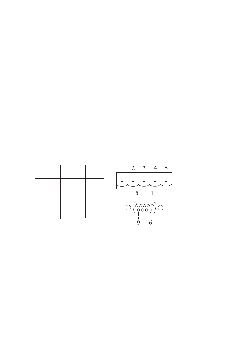
CANbus with either the screw terminals or the DB-9 connector. To
facilitate use of the screw terminals, a mating female connector has been
provided. The CANISA complies to the physical layer specification for
isolated ports, therefore bus power (V+, V-) must be present in order for its
transceiver to function. Hardware installation is completed by replacing the
computer’s cover.
Screw
Function
CAN_L
Drain
CAN_H
Not Used
Terminal DB-9
V –
V +
Connector Pin Assignments
1 3,6
2 2
3 5
4 7
5 9
— 1,4,8
SOFTWARE:
files which allows the operating system to allocate computer resources to the
card. The instructions for installing these files are provided on the disk in
the file named README.TXT.
The CANISA comes with a disk which contains the driver
TD990520-0IE
3
Page 4

CONFIGURING JUMPER SETTINGS
Power Selection
A set of four jumpers, labeled POWER, offers the choice between powering
the CANISA transceiver circuitry from the host computer or from the
CANbus. By default the jumpers are set to INT. To power the transceiver
from the CANbus, move all four jumpers to the EXT setting.
DeviceNet Reverse Voltage Protection
By default, diode D1 protects the CANISA from overvoltage which would
occur if the DeviceNet power connections were accidentally reversed. This
protection results in the CANISA ground being about 700 mV different from
the CAN ground. If desired, the CANISA ground potential can be made
equal to the CAN ground by installing a jumper on JP7.
Termination
If the CANISA is located at the end of a trunk, line-matching impedance is
required. A 121-ohm resistor is supplied for this purpose. If a different
impedance is needed, jumper JP8 should be removed and the alternative
impedance connected to screw terminals CAN_H and CAN_L.
Interrupts
Jumper block JP6 makes available all possible interrupt selections.
Interrupt 5 has been chosen as the default.
I/O Address Map
The CANISA has two modes of operation—BasicCAN and PeliCAN—that
affect how the I/O space is defined. I/O addressing is set with jumper block
JP9 using jumpers S0–S4 and RA. By default, jumper RA (Range) is open
causing the I/O space to be 32 contiguous bytes in size. This setting is used
in BasicCAN, but may also be used in PeliCAN. For full PeliCAN
functionality, jumper RA must be installed, extending the I/O space to 128
contiguous bytes.
The CANISA uses an I/O space within the range 0x000–0x3FF as illustrated
in Tables 1–3. Regardless of the RA setting, jumpers S0–S4 are used to
select the address at which the I/O space begins. The default setting is
0x300. Remember, RA determines only the size of the I/O space: 32 or 128
bytes.
An unused jumper may be left on the board with no effect, by attaching the
jumper to only one of the two pins that constitute a jumper pair.
TD990520-0IE
4
Page 5

BasicCAN Jumper Settings
(� = jumper installed)
Table 1 — 32-byte Addressing for BasicCAN
RA S4 S3 S2 S1 S0 I/O Address
� � � � � 000
� � � � 020
� � � � 040
� � � 060
� � � � 080
� � � 0A0
� � � 0C0
� � 0E0
� � � � 100
� � � 120
� � � 140
� � 160
� � � 180
� � 1A0
� � 1C0
� 1E0
� � � � 200
� � � 220
� � � 240
� � 260
� � � 280
� � 2A0
� � 2C0
� 2E0
� � � 300
� � 320
� � 340
� 360
� � 380
� 3A0
� 3C0
3E0
TD990520-0IE
5
Page 6

PeliCAN Jumper Settings
(� = jumper installed
= don’t care)
X
Table 2 — 32-byte Addressing Table 3 — 128-byte Addressing
RA S4 S3 S2 S1 S0 I/O RA S4 S3 S2 S1 S0 I/O
Address Address
� � � � � 000 � � � �
� � � � 080 � � �
� � � � 100 � � �
� � � 180 � �
� � � � 200 � � �
� � � 280 � �
� � � 300 � �
� � 380 � X 380
X
X
X
X
X
X
X
X
X 000
X 080
X 100
X 180
X 200
X 280
X 300
CAN Operation
CAN is currently described by ISO 11898. In terms of the Open Systems
Interconnection model (OSI), CAN partially defines the services for layer 1
(physical) and layer 2 (data link). Higher-layer protocols such as DeviceNet
and Smart Distributed System define additional services of the seven layer
OSI model. Both of these protocols use CAN circuitry and, therefore,
comply with the data link layer defined by CAN.
Medium access control (MAC) is accomplished through non-destructive bitwise arbitration. If a station attempting transmission fails to confirm that its
data is being accurately propagated, it assumes a higher priority message is
present on the network. Consequently, it halts transmission and reverts to
receiving mode. The highest priority message gets through and lower
priority messages are resent later. In this way network collisions do not
destroy data and eventually all stations gain access to the network.
TD990520-0IE
6
Page 7

NEED MORE HELP INSTALLING THIS PRODUCT?
More information can be found on our web site at www.ccontrols.com. Browse
the Technical Support section of our site for a look at our on-line technical
manuals, downloadable software drivers and utility programs that can test
the product. When contacting us, just ask for technical support.
Warranty
Contemporary Controls (CC) warrants its new product to the original purchaser for two years from the product shipping date. Product returned to CC
for repair is warranted for one year from the date that the repaired product is
shipped back to the purchaser or for the remainder of the original warranty
period, whichever is longer.
If a CC product fails to operate in compliance with its specification during the
warranty period, CC will, at its option, repair or replace the product at no
charge. The customer is, however, responsible for shipping the product; CC
assumes no responsibility for the product until it is received.
CC’s limited warranty covers products only as delivered and does not cover
repair of products that have been damaged by abuse, accident, disaster, misuse, or incorrect installation. User modification may void the warranty if the
product is damaged by the modification, in which case this warranty does not
cover repair or replacement.
This warranty in no way warrants suitability of the product for any specific
application. IN NO EVENT WILL CC BE LIABLE FOR ANY DAMAGES
INCLUDING LOST PROFITS, LOST SAVINGS, OR OTHER INCIDENTAL
OR CONSEQUENTIAL DAMAGES ARISING OUT OF THE USE OR
INABILITY TO USE THE PRODUCT EVEN IF CC HAS BEEN ADVISED
OF THE POSSIBILITY OF SUCH DAMAGES, OR FOR ANY CLAIM BY
ANY PARTY OTHER THAN THE PURCHASER.
THE ABOVE WARRANTY IS IN LIEU OF ANY AND ALL OTHER
WARRANTIES, EXPRESSED OR IMPLIED OR STATUTORY, INCLUDING THE WARRANTIES OF MERCHANTABILITY, FITNESS FOR
PARTICULAR PURPOSE OR USE, TITLE AND NONINFRINGEMENT.
Returning Products for Repair
Return the product to the location from which it was purchased by following
the instructions at the URL below:
www.ccontrols.com/rma.htm
DECLARATION OF CONFORMITY
Information about the regulatory compliance of this product can be found at the
URL below:
www.ccontrols.com/compliance.htm
TD990520-0IE
7
Page 8

[This page was deliberately left blank.]
TD990520-0IE
8
 Loading...