

Page 1
Digital I/O Module
BMT-DIO4/2
1108831326
1. Description
The BACnet MS/TP module with 4 digital inputs and 2 relay
outputs with manual control was developed for decentralized
switching tasks. It is suitable for accommodating, for example,
light switches and window contacts in a room, switching two light
strips or controlling louvers. It can also be used to control 2 motorized fire dampers. With strong inductive loads, we recommend
protecting the relay contacts with an RC element. The inputs can
be used as contact or voltage inputs. The inputs and outputs can
be switched and scanned by means of standard objects via a BACnet client. The module address and the baud rate are set by means
of two address switches on the front.
Suitable for decentralized mounting in serial sub-distributor.
2. Declaration of Conformity
The device was tested according to the applic able st andards. Conformit y was proofed. The declaration of conformit y is available at
the manufacturer METZ CONNECT GmbH.
Notes Regarding Device Description
These instructions include indications for use and mounting of the
device. In case of questions that cannot be answered with these
instructions please consult supplier or manufacturer.
The indicated installation dire ctions or rules are applicable to the
Federal Republic of Germany. If the device is used in other countries
it applies to the equipment installer or the user to meet the national
directions.
Safety Instructions
Keep the applicable dire ctions for industrial safety and prevention
of accidents as well as the VDE rules.
Technicians and/or installers are informed that they have to
elec trically discharge themselves as prescribed before installation or
maintenance of the devices.
Only qualified personnel shall do mounting and installation work
with the device s, see section “qualified personnel”.
The information of these instruc tions have to be read and understood by every person using this device.
7624/899299-04
Symbols
Warning of dangerous electrical voltage
Danger
means that non-obser vance may cause risk of life,
grievous bodily harm or heavy material damage.
Qualified Personnel
Qualified personne l in the sense of these instructions are per sons
who are well versed in the use and installation of such devices and
whose professional qualification meets the requirements of their
work.
This includes for example:
• Qualification to connect the device according to the VDE
specifications and the local regulations and a qualification to put
this device into operation, to power it down or to activate it by
respecting the internal directions.
• Knowledge of safety rules.
• Knowledge about application and use of the device within the
equipment sys tem etc.
3. Technical Data
BACnet Interface
Protocoll BACnet MS/TP
Transmission rate 9600 ... 115200 Bd
(factory set ting 9600 Bd)
Cabling RS485 two wire bus with voltage
equalizing cable in bus / line topology;
terminate with 120 Ohms
Supply
Operating volt age range 20 ... 28 V AC/DC (SELV)
Current consumption 200 mA (AC) / 75 mA (DC)
Relative duty cycle 100 %
Input
Voltage input 30 V AC/ DC
High-signal recognition >7 V AC/DC
Output
Output contacts 2 changeover contacts
Switching voltage max. 250 V AC
Continuous current max. 16 A / relay (80 A / 20 ms)
Total current for
all contacts 25 A
Housing
Dimensions WxHxD 2.0 x 2.8 x 3.0 in. (50 x 70 x 75 mm)
Weight 126 g
Mounting position any
Mounting standard rail TH35 per IEC 60715
Mounting in series the maximum quantity of modules
without space connected in line is limited to 15 or
to a maximum power consumption of
2 Amps (AC or DC) per connection to
the power supply. For any similar
block of additional modules a sepa rate connection to the power supply
is mandatory.
Material
Housing Polyamide 6.6 V0
Terminal blocks Polyamide 6.6 V0
Cover plate Polycarbonate
Type of protection
(IEC 60529)
Housing IP4 0
Terminal blocks IP20
Terminal blocks
Supply and bus
4 pole ter minal block max. AWG 16 (1,5 mm²) solid wireg
max. AWG 18 (1,0 mm²) stranded wire
Wire diameter min. 0.3 mm up to max. 1.4 mm
(terminal block and jumper plug are
included to each packing unit)
Module connection
Input/Output max. AWG 12 (4.0 mm²) solid wire
max. AWG 14 (2.5 mm²) stranded wire
Wire diameter min. 0.3 mm up to max 2.7 mm
Protective circuitr y polarity reversal protection of
operating voltage
polarity reversal protection of supply
and bus
Temperature range
Operation -5 °C ... +55 °C
Storage -20 °C ... +70 °C
Display
Operating / bus ac tivity green LED
Error indication red LED
Status of the
inputs & outputs yellow LED
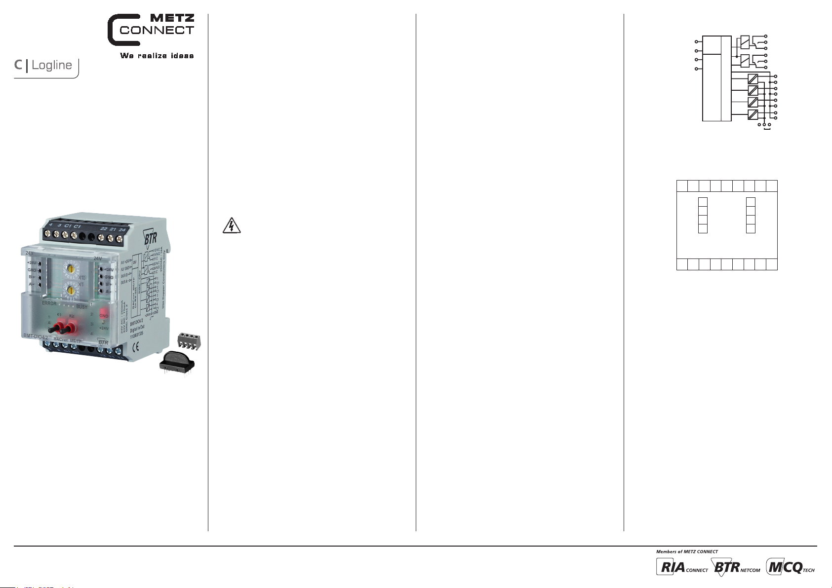
4. Wiring Diagram
A1/+24 V
A2 /GND
BUS B+
BUS A-
24 V
BACnet MS/TP
on RS-485
5. Connection Diagram
4 3 C1 C1 22 21 24
24 V AC/DC
A1
A2
BUS B+
B+
BUS A-
A-
1 2 C1 C1 12 11 14
RISC - CPU
GND
A1
A2
B+
12 N.C.
14 N.O.
11 C
22 N.C.
24 N.O.
21 C
1
C1
2
C1
3
C1
4
C1
GND+24 V
J
A-
METZ CONNECT GmbH | Im Tal 2 | 78176 Blumberg | Germany
Phone +49 7702 533-0 | Fax +49 7702 533-433
Mounting instruction see www.metz-connect.com
Page 2
6. Mounting
Power down the equipment
Mount the module on standard rail (TH35 per IEC 60715 in
junction boxes and/or on distribution panels).
Installation
Electric installation and device termination shall be done by qualifie d persons only, by re spec ting all ap plicab le
specifications and regulations.
Plug in the terminal block for bus connection
21
Connect the cable for bus supply
5 mm
7. Network adress and Bit rate setting
Configuration Switches
Hexadecimal Switches x10, x1 define the Network-Address
(00 - F9; e.g. F9h = 15x16+9 = 249d) and Baudrate (FA – FF).
• Turn Switch x10 to E (Device is temporaryly configured as Slave)
• Turn Switch x1 to A – F to select Baudrate
• Turn Switch x10 to F, wait 1 Second
• Red and green LEDs are blinking when Baudrate ist stored in
EEPROM
• Turn Switch x10 to select Network-Address
• Turn Switch x1 to select Network-Address
Adress switch x10 F F F F F F
Adress switch x1 A B C D E F
Bitrate (Bit/s) 9600 19200 38400 57600 76800 115200
Factor y setting: 9600 Bit /s
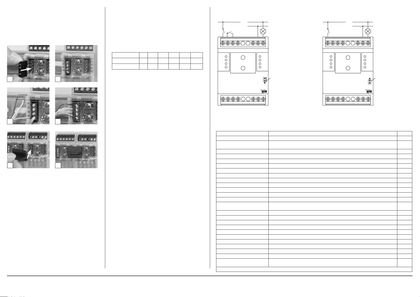
8. Connection examples
Connection examples 1+2
A1 (24 V AC /DC) N
4 3 C1 C1 22 21 24
24V
+24 V
GND
B+
A-
ERROR
BMT-DIO4/2
1 2 C1 C1 12 11 14
L
X10
X1
BUSY
BACnet MS/TP
1
2
3
4
24V
+24 V
GND
B+
A-
Jumper unter
der Blende
Jumper below
the faceplate
Connection example 3
A2 (GND) N
4 3 C1 C1 22 21 24
24V
+24 V
GND
B+
A-
ERROR
BMT-DIO4/2
1 2 C1 C1 12 11 14
L
X10
X1
BUSY
BACnet MS/TP
24V
+24 V
GND
B+
A-
1
Jumper unter
2
der Blende
3
Jumper below
the faceplate
4
43
Mounting in series
5 6
The module can be aligned without interspace. Use the jumper
plug to connect bus and supply voltage when the modules are
mounted in series.
The max imum quan tity of m odules connec ted in line is limite d
to 15 or to a maximum power c onsumpt ion of 2 Amp s (AC or
DC) pe r connec tion to the power supply. For any similar b lock
of additional modules a se parate connect ion to the p ower
supply is mandatory.
9. Software Description
Device Object
Property Remark / Value RW
Object_Identifier device, default instance: 421000 + Network-Address RW-E
Object_Name
Obj ec t_Ty pe DEVICE (8) R
System_Status OPERATIONAL (0) R
Vendor_Name “BTR Netcom GmbH” R
Vendor_Identifier 421 R
Model_Name “BMT-DIO4/2” R
Description max. 127 Bytes, default “” RW-E
Location max. 63 By tes, default “” RW-E
Firmware_Revision “1.2” R
Application_Software_Version “1. 0” R
Protocol_Version 1 R
Protocol_Revision 12 R
Protocol_Services_Supported
Protocol_Object_Types_Supported DEVICE, BINARY_OUTPUT, BINARY_INPUT, GROUP, ANALOG_VALUE R
Ob je ct_L is t [11] device, binary-output 1…2, binary-input 1…4, group 1…3, analog-value 1 R
Max_APDU_Length_Accepted 480 R
Segmentation_Supported NO_SEGMENTATION (3) R
APDU_Time out 10000 R
Number_Of_APDU_Retries 3 R
Device_Address_Binding - R
Database_Revision 0 R
Max_Master 0…127, de faul t 127 RW-E
Max_Info_Frames 1…255, default 1 RW-E
Active_COV_Subscriptions
R: Read Proper ty, W: Write Proper ty, -E: Storage in EEPROM / Flash
max. 63 B ytes,
default “BMT-DIO4/2_” + Network-Address (Hexade cimal)
read-property, write-property, subscribe-cov, who-has, who-is, device-communicationcontrol, reinitialize-device
max. 8 Subscriptions, for binary-input / binary-output,
Confirmed / Unconfirme d, Lifetime = 0…65535 sec.
RW-E
R
R
METZ CONNECT GmbH | Im Tal 2 | 78176 Blumberg | Germany
Phone +49 7702 533-0 | Fax +49 7702 533-433
Mounting instruction see www.metz-connect.com
Page 3

Continuation Software Description
Binar y Output Object 1…2
Property Remark / Value RW
Object_Identifier binary-output, instance 1 … 2 R
Obj ec t_Ty pe BINARY_OUTPUT (4) R
Object_Name max. 42 Bytes, default “Relay 1” … “Relay 2” RW-E
Description max. 84 Byte s, default “” RW-E
Pre sent_Va lue NULL (write only) / INACTIVE (0) / AC TIVE (1) RW
IN_ALARM: 0
Status_Flags
Event_State NORMA L (0) R
Out_Of_Service FALSE (0) / TRUE (1) RW
Polarity NORMA L (0) / REVERSE (1) RW-E
Priority_Array [16] NULL / INACTIVE (0) / ACTIVE (1) R
Relinquish_Default INACTIVE (0) R
Inactive_Text max. 20 B ytes, default “Off” RW-E
Activ e_Te xt max. 20 By tes, default “On” RW-E
Notification_Class
R: Read Proper ty, W: Write Proper ty, -E: Storage in EEPROM / Flash
Function Table for Binary Output
Out_Of_Service Polarity Switch Priority_Array Pre sent_Va lue Binary Output OVERRIDDEN
0 0 A NULL / 0 / 1 0 / 0 / 1 0 / 0 / 1 0 0
0 0
0 1 A NULL / 0 / 1 0 / 0 / 1 1 / 1 / 0 0 0
0 1
1 0 A NULL / 0 / 1 0 / 0 / 1 0 0 1
1 0
1 1 A NULL / 0 / 1 0 / 0 / 1 1 0 1
1 1
FAULT: 0
OVERRIDDEN: 0 = Switch A (Auto)
1 = Switch 0 (Off ) or 1 (On)
OUT_OF_SERVICE: 0 / 1
Unsubscribed UnconfirmedCOVNotification
0: no COV notification, default,
1: local broadcast,
2: global broadcast
0
1
0
1
0
1
0
1
NULL / 0 / 1
NULL / 0 / 1
NULL / 0 / 1
NULL / 0 / 1
NULL / 0 / 1
NULL / 0 / 1
NULL / 0 / 1
NULL / 0 / 1
0
1
1
0
0 / 0 / 1
0 / 0 / 1
0 / 0 / 1
0 / 0 / 1
OUT_OF_SERVICE
0
1
0
1
0
1
0
1
1 0
1 0
0 1
0 1
R
RW-E
Continuation Software Description
Binar y Input Object 1…4
Property Remark / Value RW
Object_Identifier binary-input, instance 1 … 4 R
Obj ec t_Ty pe BINARY_INPUT (3) R
Object_Name max. 42 Bytes, default “Input 1” … “Input 4” RW-E
Description max. 84 Byte s, default “” RW-E
Pre sent_Va lue
Status_Flags
Event_State NORMA L (0) R
Out_Of_Service FALSE (0) / TRUE (1) RW
Polarity NORMA L (0) / REVERSE (1) RW-E
Inactive_Text max. 20 B ytes, default “Off” RW-E
Activ e_Te xt max. 20 By tes, default “On” RW-E
Notification_Class
R: Read Proper ty, W: Write Proper ty, -E: Storage in EEPROM / Flash
Function Table for Binary Input
Out_Of_Service Polarity BinaryInput Present _Valu e OUT_OF_ SERVICE
0 0
0 1
1 0
1 1
x: Present_Value is writable and not affected by inputs
Group Object 1…3
Property Remark / Value RW
Object_Identifier group, instance 1 … 3 R
Obj ec t_Ty pe GROUP (11) R
Object_Name max. 42 Bytes, default “Group 1” … “Group 3” RW-E
Description max. 84 Byte s, default “” RW-E
Pre sent_Va lue
List_Of_Group _Members see next Table R
R: Read Proper ty, W: Write Proper ty, -E: Storage in EEPROM / Flash
Members of Groups
Group
1 x x x x
2 x x
3 x x
Binary Input
1 2 3 4
INACTIVE (0) / ACTIVE (1),
writable if Out_Of_Service
IN_ALARM: 0
FAULT: 0
OVERRIDDEN: 0
OUT_OF_SERVICE: 0 / 1
Unsubscribed UnconfirmedCOVNotification
0: no COV notification, default,
1: local broadcast,
2: global broadcast
0
1
0
1
0
1
0
1
Present_Value of Binary Inputs,
see next Table
0
1
1
0
x 1
x 1
0
0
R
RW
R
RW-E
R
METZ CONNECT GmbH | Im Tal 2 | 78176 Blumberg | Germany
Phone +49 7702 533-0 | Fax +49 7702 533-433
Mounting instruction see www.metz-connect.com
Page 4

Continuation Software Description
Analog Value Object 1
Property Remark / Value RW
Object_Identifier analog-value, instance 1 R
Obj ec t_Ty pe ANALOG_VALUE (2) R
Object_Name max. 42 Bytes, default “Watchdog Time” RW-E
Description max. 84 Byte s, default “” RW-E
Pre sent_Va lue
Status_Flags
Event_State NORMA L (0) R
Out_Of_Service FALSE (0) R
Units seconds (73) R
R: Read Proper ty, W: Write Proper ty, -E: Storage in EEPROM / Flash
The Watchdog Timer resets Pres ent_Value of all output objec ts to Relinquish _Default, if BACnet communication fails permanently. The timer is re started, when a BACnet message with an APDU is re ceive d.
When the timer times out, the priority arrays of all output objects are completely cleared to NULL.
Time Constant of Watchdog Timer,
0: Watchdog is inactive, Maximum: 655.34 seconds
IN_ALARM: 0
FAULT: 0
OVERRIDDEN: 0
OUT_OF_SE RVICE: 0
RW-E
R
METZ CONNECT GmbH | Im Tal 2 | 78176 Blumberg | Germany
Phone +49 7702 533-0 | Fax +49 7702 533-433
Mounting instruction see www.metz-connect.com
 Loading...