

Page 1
Digital Input Module
BMT-DI10
1108811319
1. Description
The BACnet MS/TP module with 10 digital inputs was developed for
decentralized switching tasks. It is suitable for detecting potential-free
switch states, for example electrical limit switches on vent valves or auxiliary contacts of power contactors. The inputs can be used as contact
or voltage inputs. The inputs can be scanned by means of standard
objects via a BACnet client. The module is addressed and the baud
rate is set by means of two address switches on the front.
Suitable for decentralized mounting in serial sub-distributor.
2. Declaration of Conformity
The device was tested according to the applic able st andards. Conformit y was proofed. The declaration of conformit y is available at
the manufacturer METZ CONNECT GmbH.
Notes Regarding Device Description
These instructions include indications for use and mounting of the
device. In case of questions that cannot be answered with these
instructions please consult supplier or manufacturer.
The indicated installation dire ctions or rules are applicable to the
Federal Republic of Germany. If the device is used in other countries
it applies to the equipment installer or the user to meet the national
directions.
Safety Instructions
Keep the applicable directions for industrial safety and prevention of
accidents as well as the VDE rules.
Technicians and/or installers are informed that they have to
electrically discharge themselves as prescribed before installation or
maintenance of the devices.
Only qualified personnel shall do mounting and installation work with
the devices, see section “qualified personnel”.
The information of these instructions have to be read and understood
by every person using this device.
7622/899299-02
Symbols
Warning of dangerous electrical voltage
Danger
means that non-observance may cause risk of life,
grievous bodily harm or heavy material damage.
Qualified Personnel
Qualified personnel in the sense of these instructions are persons who
are well versed in the use and installation of such devices and whose
professional qualification meets the requirements of their work.
This includes for example:
• Qualification to connect the device according to the VDE
specifications and the local regulations and a qualification to put
this device into operation, to power it down or to activate it by
respecting the internal directions.
• Knowledge of safety rules.
• Knowledge about application and use of the device within the
equipment sys tem etc.
3. Technical Data
BACnet Interface
Protocoll BACnet MS/TP
Transmission rate 9600 to 115200 Bd
(factory set ting 9600 Bd)
Cabling RS485 two wire bus with voltage
equalizing cable in bus / line topology
terminate with 120 Ohms
Supply
Operating volt age range 20 to 28 V AC/ DC (SELV)
Current consumption 85 mA (AC) / 75 mA (DC)
Relative duty cycle 100 %
Input
Input voltage 30 V DC
High-signal recognition >7 V AC/DC
Housing
Dimensions WxHxD 1.4 x 2.8 x 2.6 in. (35 x 70 x 65 mm)
Weight 83 g
Mounting position any
Mounting standard rail TH35 per IEC 60715
Mounting in series the maximum quantity of modules
without space connected in line is limited to 15 or
to a maximum power consumption of
2 Amps (AC or DC) per connection to
the power supply. For any similar
block of additional modules a
separate connection to the power
supply is mandator y.
Material
Housing Polyamide 6.6 V0
Terminal blocks Polyamide 6.6 V0
Cover plate Polycarbonate
Type of protection
(IEC 60529)
Housing IP4 0
Terminal blocks IP20
Terminal blocks
Supply and bus
4 pole ter minal block max. AWG 16 (1.5 mm²) solid wire
max. AWG 18 (1.0 mm²) stranded wire
Wire diameter min. 0.3 mm up to max. 1.4 mm
(terminal block and jumper plug are
included to each packing unit)
Module connection
Inputs max. AWG 12 (4.0 mm²) solid wire
max. AWG 14 (2.5 mm²) stranded wire
Wire diameter min. 0.3 mm up to max 2.7 mm
Protective circuitr y polarity reversal protection of
operating voltage
polarity reversal protection of supply
and bus
Temperature range
Operation -5 °C to +55 °C
Storage -20 °C to +70 °C
Display
Operating / bus ac tivity green LED
Error indication red LED
Status of the inputs yellow LED
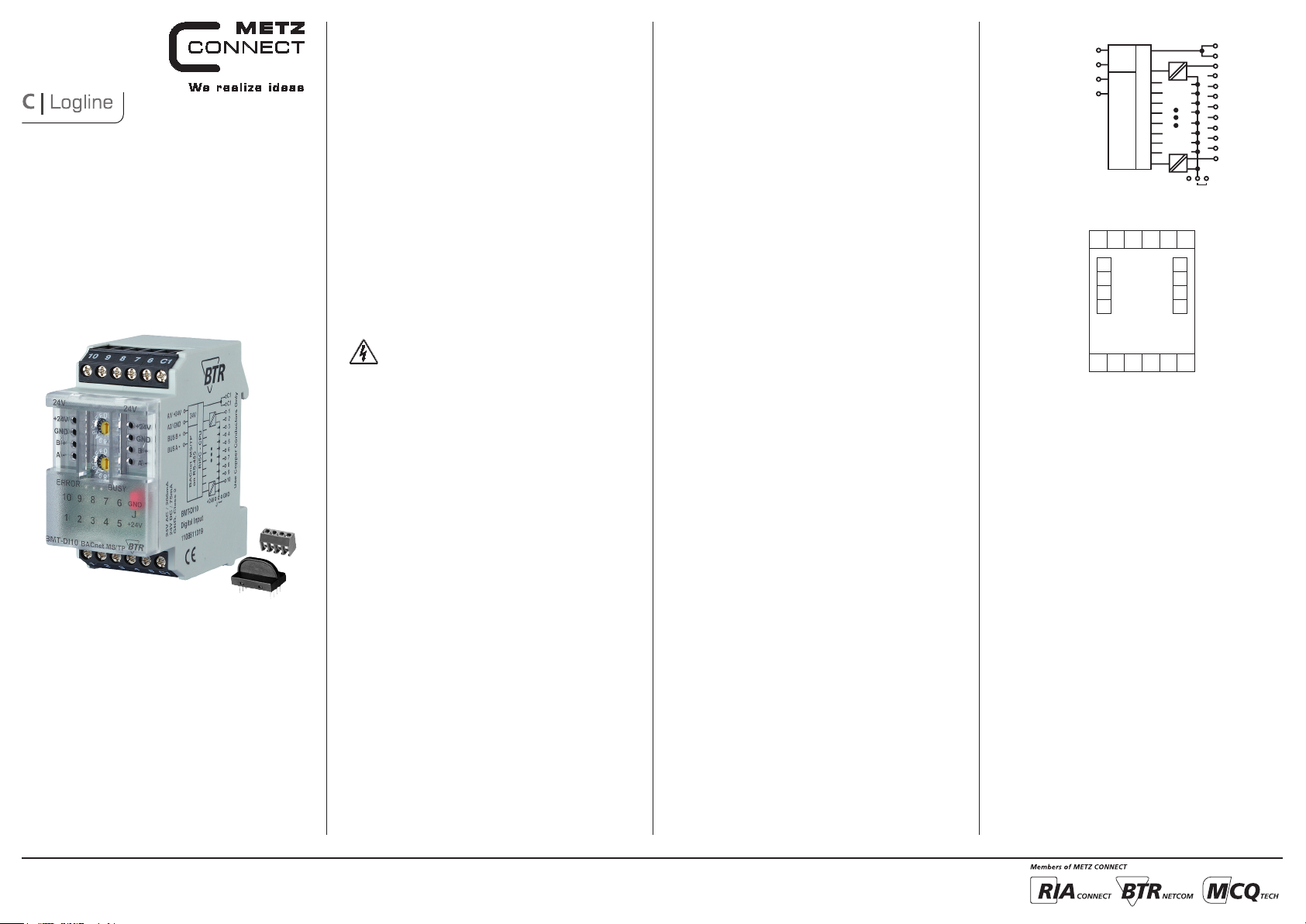
4. Wiring Diagram
A1/+24 V
A2 /GND
BUS B+
24 V
BUS A-
BACnet MS/TP
5. Connection Diagram
9876C110
24 V AC/DC
A1
A2
BUS B+
B+
BUS A-
A-
21354
RISC - CPU
on RS-485
+24 V GND
GND
A1
A2
B+
C1
C1
1
2
3
4
5
6
7
8
9
10
J
A-
C1
METZ CONNECT GmbH | Im Tal 2 | 78176 Blumberg | Germany
Phone +49 7702 533-0 | Fax +49 7702 533-433
Mounting instruction see www.metz-connect.com
Page 2
6. Mounting
Power down the equipment
Mount the module on standard rail (TH35 per IEC 60715 in
junction boxes and/or on distribution panels).
Installation
Electric installation and device termination shall be done by qualifie d persons only, by re spec ting all ap plicab le
specifications and regulations.
Plug in th e terminal block fo r bus connectio n
Conne ct the ca ble for bus supply
5 mm
21
7. Network adress and Bit rate setting
Configuration Switches
Hexadecimal Switches x10, x1 define the Network Address
(00 - F9; e.g. F9h = 15x16+9 = 249d) and Baud rate (FA – FF).
• Turn Switch x10 to E (Device is temporaryly configured as Slave)
• Turn Switch x1 to A – F to select Baud rate
• Turn Switch x10 to F, wait 1 second
• Red and green LEDs are blinking when Baud rate ist stored in
EEPROM
• Turn Switch x10 to select Network Address
• Turn Switch x1 to select Network Address
MS/ TP Master if using Network Address 0x00 … Max_Master,
MS/ TP Slave if using Network Address Max_Master + 1 … 0xF9.
Adress switch x10 F F F F F F
Adress switch x1 A B C D E F
Bit rate (Bit/s) 9600 19200 38400 57600 76800 115200
Factor y setting: 9600 Bit /s
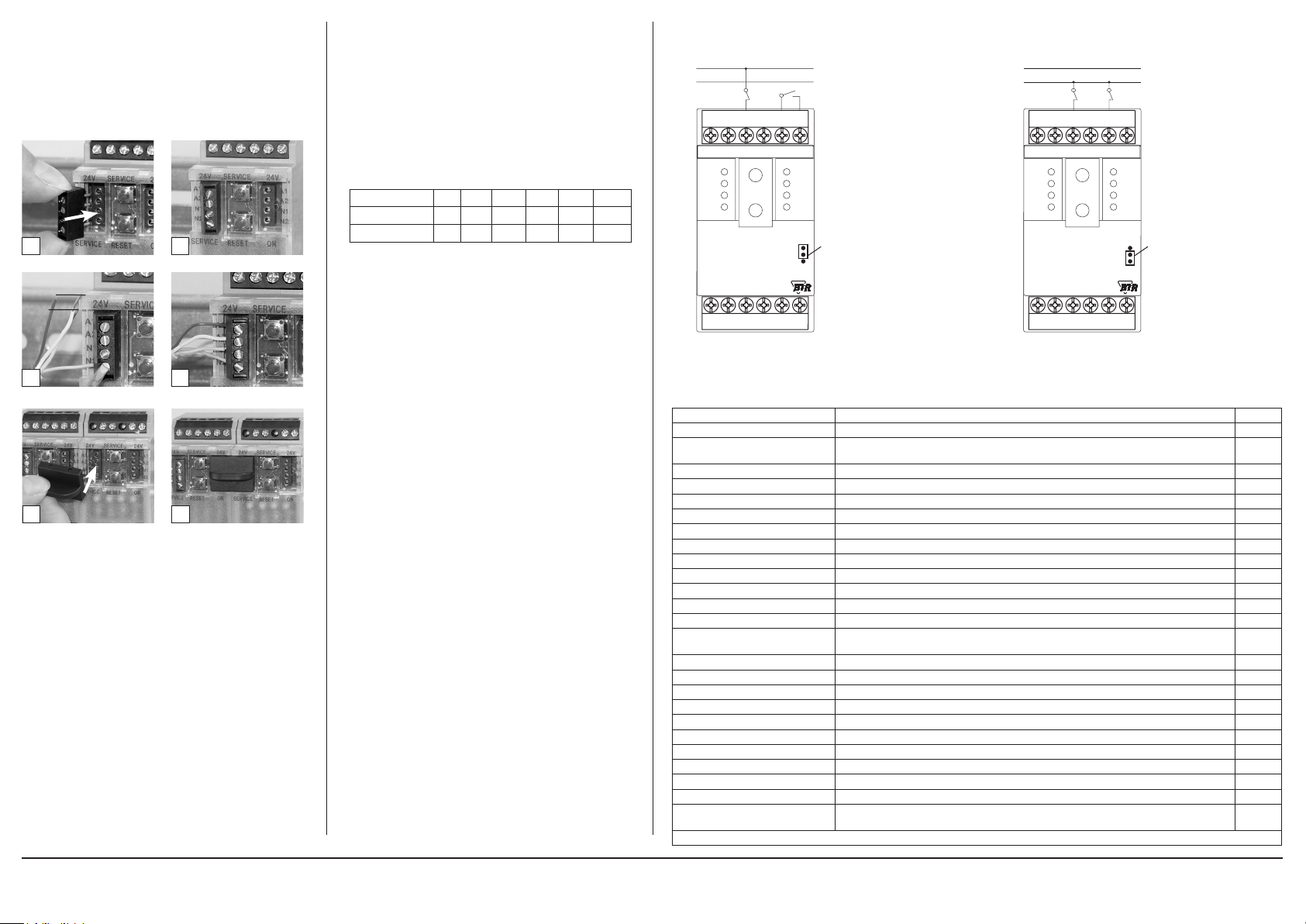
8. Connection examples
Connection examples 1+2
A1 (24 V AC /DC)
A2 (GND)
910 8 67 C1
24V
+24 V
GND
B+
A-
ERROR
1019283746
BMT-DI10
21 3 54 C1
BACnet MS/TP
24V
+24 V
GND
X10
B+
X1
A-
BUSY
5
Jumper unter
der Blende
Jumper below
the faceplate
Connection example 3
A1 (24 V AC /DC)
A2 (GND)
910 8 67 C1
24V
+24 V
GND
B+
A-
BMT-DI10
X10
X1
ERROR
1019283746
BACnet MS/TP
21 3 54 C1
BUSY
5
24V
+24 V
GND
B+
A-
Jumper unter
der Blende
Jumper below
the faceplate
43
Mounting in seri es
5 6
The mod ule can be a ligned w ithout i ntersp ace. Use th e jumper
plug to connect b us and supp ly voltage when t he modul es are
mounte d in series.
The maximum quantity of modules connected in line is limited
to 15 or to a maximum power consumption of 2 Amps (AC or
DC) per connection to the power supply. For any similar block of
additional modules a separate connection to the power supply is
mandatory.
9. Software Description
Device Object
Property Remark / Value RW
Object_Identifier device, default instance: 421000 + Network-Address RW-E
Object_Name
Obj ec t_Ty pe DEVICE (8) R
System_Status OPERATIONAL (0) R
Vendor_Name “BTR Netcom GmbH” R
Vendor_Identifier 421 R
Model_Name “BMT-DI10” R
Description max. 127 Bytes, default “” RW-E
Location max. 63 By tes, default “” RW-E
Firmware_Revision “1.2” R
Application_Software_Version “1. 0” R
Protocol_Version 1 R
Protocol_Revision 12 R
Protocol_Services_Supported
Protocol_Object_Types_Supported DEVICE, BINARY_INPUT, GROUP R
Objec t_L ist [22] device, binary-input 1…10, group 1…11 R
Max_APDU_Length_Accepted 480 R
Segmentation_Supported NO_SEGMENTATION (3) R
APDU_Time out 10000 R
Number_Of_APDU_Retries 3 R
Device_Address_Binding - R
Database_Revision 0 R
Max_Master 0…127, de faul t 127 RW-E
Max_Info_Frames 1…255, default 1 RW-E
Active_COV_Subscriptions
R: Read Proper ty, W: Write Proper ty, -E: Storage in EEPROM / Flash
max. 63 B ytes,
default “BMT-DI10_” + Network-Address (Hexadecimal)
read-property, write-property, subscribe-cov, who-has, who-is, device-communicationcontrol, reinitialize-device
max. 12 Subscriptions, for binary-input 1…10,
Confirmed / Unconfirme d, Lifetime = 0…65535 sec.
RW-E
R
R
METZ CONNECT GmbH | Im Tal 2 | 78176 Blumberg | Germany
Phone +49 7702 533-0 | Fax +49 7702 533-433
Mounting instruction see www.metz-connect.com
Page 3

Continuation Software Description
Binar y Input Object 1…10
Property Remark / Value RW
Object_Identifier binary-input, instance 1 … 10 R
Obj ec t_Ty pe BINARY_INPUT (3) R
Object_Name max. 42 Bytes, default “Input 1” … “Input 10” RW-E
Description max. 84 Byte s, default “” RW-E
Pre sent_Va lue
Status_Flags
Event_State NORMA L (0) R
Out_Of_Service FALSE (0) / TRUE (1) RW
Polarity NORMA L (0) / REVERSE (1) RW-E
Inactive_Text max. 20 B ytes, default “Off” RW-E
Activ e_Te xt max. 20 By tes, default “On” RW-E
Notification_Class
R: Read Proper ty, W: Write Proper ty, -E: Storage in EEPROM / Flash
INACTIVE (0) / ACTIVE (1),
writable if Out_Of_Service
IN_ALARM: 0
FAULT: 0
OVERRIDDEN: 0
OUT_OF_SERVICE: 0 / 1
Unsubscribed UnconfirmedCOVNotification
0: no COV notification, default,
1: local broadcast,
2: global broadcast
R
RW
R
RW-E
Continuation Software Description
Members of Groups
Group
1 x x x x x x x x x x
2 x x x x x x x
3 x x x x x x x
4 x x x x x x
5 x x x x x
6 x x x x x
7 x x x x
8 x x x
9 x x x
10 x x
11 x x
Binary Input
1 2 3 4 5 6 7 8 9 10
Out_Of_Service Polarity Binary Input P resent_Val ue OUT_OF_ SERVI CE
0 0
0 1
1 0
1 1
x: Present_Value is writable and not affected by inputs
0
1
0
1
0
1
0
1
0
1
1
0
x 1
x 1
0
0
Group Object 1…11
Property Remark / Value RW
Object_Identifier group, instance 1 … 11 R
Obj ec t_Ty pe GROUP (11) R
Object_Name max. 42 Bytes, default “Group 1” … “Group 11” RW-E
Function Table for Binary Input
Description max. 84 Byte s, default “” RW-E
Pre sent_Va lue
List_Of_Group _Members see next Table R
R: Read Proper ty, W: Write Proper ty, -E: Storage in EEPROM / Flash
Present_Value of Binary Inputs,
see next Table
R
METZ CONNECT GmbH | Im Tal 2 | 78176 Blumberg | Germany
Phone +49 7702 533-0 | Fax +49 7702 533-433
Mounting instruction see www.metz-connect.com
 Loading...