

Page 1
Analog Input Module
BMT-AI8
11088213
1. Description
The BACnet MS/TP module with 8 individually configurable
resistance or voltage input s is designed for local s witching
operations. It is suitable to record resistance or voltage values of for
example passive and active temperature sensors electric al
ventilation or mixing valves, valve positions etc. The inputs are
univer sally configurable by standard object via a BACnet-Client.
Addressing of the module and baud rate set ting are done with the
two address switches (x1 / x10) on the front. Possible settings are
addresses 00 to F9 and baud rates 9600 Bd, 19200 Bd, 384 00 Bd,
57600, 7680 0 Bd and 115200 Bd.
2. Declaration of Conformity
The device was te sted according to the applicable standards. Conformit y was proofed. The declaration of conformity is available at
the manufacturer METZ CONNECT GmbH.
Notes Regarding Device Description
These instructions include indications for use and mounting of the
device. In case of questions that cannot be answered with these
instructions please consult supplier or manufacturer.
The indicated installation directions or rules are applicable to the
Federal Republic of Germany. If the device is used in other countries
it applies to the equipment installer or the user to meet the national
directions.
Safety Instructions
Keep the applic able directions for industrial safety and prevention
of accidents as well as the VDE rule s.
Technicians and/or installers are informed that they have to
elec trically discharge themselves as prescribed before installation or
maintenance of the devices.
Only qualified pers onnel shall do mounting and installation work
with the devices, see section “qualified personnel”.
The information of these instructions have to be read and understood by ever y person using this device.
7603/899299-03
Symbols
Warning of dangerous electrical voltage
Danger
means that non-observance may cause risk of life,
grievous bodily harm or heavy material damage.
Qualified Personnel
Qualified personnel in the sense of these instructions are per sons
who are well versed in the use and installation of such devices and
whose professional qualification meets the requirements of their
work.
This includes for example:
• Qualification to connect the device according to the VDE
specifications and the local regulations and a qualification to put
this device into operation, to power it down or to activate it by
respecting the internal directions.
• Knowledge of safet y rules.
• Knowledge about application and use of the device within the
equipment system etc.
3. Technical Data
BACnet Interface
Protocoll BACnet MS/ TP
Transmission rate 9600 ... 115200 Bd
(factory setting 9600 Bd)
Cabling RS485 two wire bus with voltage
equalizing cable in bus / line topology;
terminate with 120 Ohms
Supply
Operating voltage range 20 ... 28 V AC/DC (SELV)
Current consumption 65 mA (AC) / 25 mA (DC)
Relative duty cycle 100 %
Input
Resistance range 40 Ohms to 4 MOhms
Voltage input 0 ... 10 V DC
Resolution 10 mV
Error about ±100 mV
Housing
Dimensions Wx HxD 2.0 x 2.8 x 2.6 in. (50 x 70 x 65 mm)
Weight 104 g
Mounting position any
Mounting standard rail TH35 per IEC 60715
Mounting in series the maximum quantity of modules
without space connected in line is limited to 15 or
to a maximum power consumption of
2 Amps (AC or DC) per connection to
the power supply. For any similar
block of additional modules a
separate connection to the power
supply is mandatory.
Material
Housing Polyamide 6.6 V0
Terminal blocks Polyamide 6.6 V0
Cover plate Polycarbonate
Type of protection
(IEC 60529)
Housing IP4 0
Terminal blocks IP20
Terminal blocks
Supply and bus
4 pole te rminal block max. AWG 16 (1.5 mm²) solid wire
max. AWG 18 (1.0 mm²) stranded wire
Wire diameter min. 0.3 mm up to max. 1.4 mm
(terminal block and jumper plug are
included to each packing unit)
Module connection
Inp ut/Output max. AWG 12 (4.0 mm²) solid wire
max. AWG 14 (2.5 mm²) stranded wire
Wire diameter min. 0.3 mm up to max 2.7 mm
Protective circuitry polarity reversal prote ction of
operating voltage
polarity reversal prote ction of supply
and bus
Temperature range
Operation -5 °C ... +55 °C
Storage -20 °C ... +70 °C
Display
Operating and bus activity green L ED
Error indication red LED
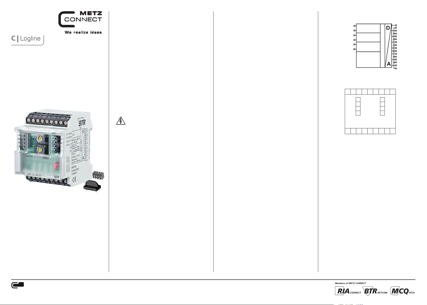
4. Wiring Diagram
A1/+24 V
A2 /GND
BUS B+
BUS A-
24 V
BACnet MS/TP
on RS-485
Outputs:
S
Voltage 15 V DC
S
or 24 V AC/DC
Inputs:
Voltage: 0-10 V
Resistance:
40 Ohm - 4MOhm
5. Connection Diagram
8 C2 7 C2 6 C2 5 C2 S
24 V AC/DC
A1
A2
B+
A-
1 C2 2 C2 3 C2 4 C2 S
GND
BUS B+
BUS A-
RISC - CPU
A1
A2
B+
A-
8
C2
7
C2
6
C2
5
C2
4
C2
3
C2
2
C2
1
C2
METZ CONNECT GmbH
Im Tal 2 | 78176 Blumberg | Germany | Phone +49 7702 533-0 | Fax +49 7702 533-433
Mounting instruction see ww w.metz-connect.com
Page 2
6. Mounting
Power down the equipment
Mount the module on standard rail ( TH35 per IEC 60715 in
junction boxes and/or on distribution panels).
Installation
Electric installation and device termination shall be done by qualifie d pers ons only, by respe cting all applicable
specifications and regulations.
Plug in the terminal block for bus connection
1
2
Connect the cable for bus supply
5 mm
43
Mounting in series
5 6
The module can be aligned without inter space. Use the jumper
plug to connect bus and supply voltage when the modules are
mounted in series.
The max imum qua ntity of modules connecte d in line is limited
to 15 or to a maximum powe r consumption of 2 A mps (AC o r
DC) pe r conne ction to the power suppl y. For any similar block
of additional mo dules a s eparate conne ction to the pow er
supply is mandatory.
7. Network adress and Bit rate setting
Configuration Switches
Hexadecimal Switches x10, x1 define the Network Address
(00 - F9; e.g. F9h = 15x16+9 = 249d) and Baud rate (FA – FF).
• Turn Switch x10 to E (Device is temporaryly configured as Slave)
• Turn Switch x1 to A – F to select Baud rate
• Turn Switch x10 to F, wait 1 second
• Red and green LEDs are blinking when Baud rate ist stored in
EEPROM
• Turn Switch x10 to select Network Address
• Turn Switch x1 to select Network Address
MS/ TP Master if using Network Address 0 x00 … Max_Master,
MS/ TP Slave if using Network Address Max_Master + 1 … 0xF9.
Adress switch x10 F F F F F F
Adress switch x1 A B C D E F
Bit rate (Bit/s) 9600 19200 38400 57600 76800 115200
Factor y set ting: 9600 Bit/s
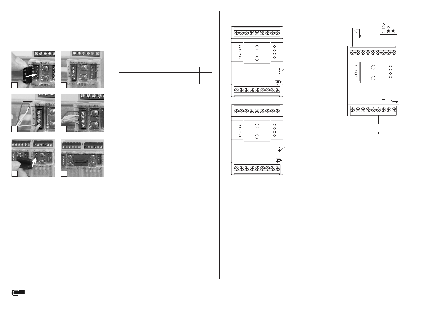
8. Jumper positions for voltage feeding
of active sensors
8 C2 7 C2 6 C2 5 C2 S
24V
+24 V
GND
B+
A-
BMT-AI8
1 C2 2 C2 3 C2 4 C2 S
8 C2 7 C2 6 C2 5 C2 S
24V
+24 V
GND
B+
A-
BMT-AI8
1 C2 2 C2 3 C2 4 C2 S
X10
ERROR
BACnet MS/TP
X10
ERROR
BACnet MS/TP
24V
+24 V
GND
BUSY
BUSY
B+
A-
1
2
3
4
24V
+24 V
GND
B+
A-
1
2
3
4
Jumper unter der Blende
Jumper below the faceplate
Jumper unten:
Klemmen S = 15 V DC
(Werkseinstellung)
Jumper in bottom position:
Contacts S = 15 V DC
(Facotry setting)
Jumper unter der Blende
Jumper below the faceplate
Jumper oben:
Klemmen S = 24 V AC/DC
Jumper in top position:
Contacts S = 24 V AC/DC
X1
X1
9. Connection examples
Passiver Fühler
Passive sensor
8 C2 7 C2 6 C2 5 C2 S
24V
+24 V
GND
B+
A-
BMT-AI8
1 C2 2 C2 3 C2 4 C2 S
Halbleiter Sensor
Semiconductor sensor
ERROR
Pullup Widerstand
Pullup resistor
BACnet MS/TP
X10
X1
BUSY
Aktiver Fühler
Active sensor
24V
+24 V
GND
B+
A-
1
24 V
2
J
3
15 V
4
METZ CONNECT GmbH
Im Tal 2 | 78176 Blumberg | Germany | Phone +49 7702 533-0 | Fax +49 7702 533-433
Mounting instruction see ww w.metz-connect.com
Page 3

10. Software Description
Device Object
Property Remark / Value RW
Object_Identifier device, default instance: 421000 + Network-Address RW-E
Object_Name
Obj ec t_Type DEVICE (8) R
System_Status OPERATIONAL (0) R
Vendor_Name “BTR Netcom GmbH” R
Vendor_Identifier 421 R
Model_Name “BMT-AI8” R
Description max. 127 Bytes, default “” RW-E
Location max. 63 By tes, default “” RW-E
Firmware_Revision “1.2 ” R
Application_Software_Version “1” R
Protocol_Version 1 R
Protocol_Revision 12 R
Protocol_Services_Supported
Protocol_Object_Types_Supported
Objec t_List [49]
Max_APDU_Length_Accepted 480 R
Segmentation_Supported NO_SEGMENTATION (3) R
APDU_Timeout 10000 R
Number_Of_APDU_Retries 3 R
Device_Address_Binding - R
Database_Revision 0 R
Max_Master 0…127, d efa ul t 127 RW-E
Max_Info_Frames 1…255, default 1 RW-E
Active_COV_Subscriptions
R: Read Proper ty, W: Write Propert y, -E: Storage in EEPROM / Flash
Analog Input Object 1…8
Property Remark / Value RW
Object_Identifier analog-input, instance 1 … 8 R
Obj ec t_Type ANALOG_INPUT (0) R
Object_Name max. 42 Bytes, default “Input 1” … “Input 8” RW-E
Description max. 84 Bytes, default “” RW-E
Pre sent_Value
Status_Flags
Event_State NORMAL (0) R
Out_Of_Service FALSE (0) / TRUE (1) RW
Units Defined in Multistate Value 1…8 R
COV_Increment
Notification_Class
R: Read Proper ty, W: Write Propert y, -E: Storage in EEPROM / Flash
METZ CONNECT GmbH
Im Tal 2 | 78176 Blumberg | Germany | Phone +49 7702 533-0 | Fax +49 7702 533-433
Mounting instruction see ww w.metz-connect.com
max. 63 B ytes,
default “BMT-AI8_” + Network-Address (Hexadecimal)
read-property, write-property, subscribe-cov, who-has, who-is,
device-communication-control, reinitialize-device
DEVICE, ANALOG_INPUT, ANALOG_VALUE,
MULTISTATE_VALUE, GROUP
device, analog-input 1…8, analog-value 1…28,
multistate-value 1…9, group 1…3
max. 10 Subscriptions, for analog-input 1…8,
Confirmed / Unconfirmed, Lifetime = 0…65535 sec.
Measured value,
writable if Out_Of_Service,
Measurement Range defined in Multis tate Value 1…8
IN_ALARM: 0
FAULT: 0
OVERRIDDEN: 0
OUT_OF_SERVICE: 0 / 1
Minimum change of Present_Value for COV notification,
default 1.0
Unsubscribed UnconfirmedCOVNotification
0: no COV notification, default,
1: local broadcast,
2: global broadcast
RW-E
R
R
R
R
R
RW
R
RW-E
RW-E
Continuation Software Description
Analog Value Object 21…28
Property Remark / Value RW
Object_Identifier analog-value, instance 21 … 28 R
Obj ec t_Type ANALOG_VALUE (2) R
Object_Name max. 42 Bytes, default “Offset 1” … “Offset 8” RW-E
Description max. 84 Bytes, default “” RW-E
Pre sent_Value
Status_Flags
Event_State NORMAL (0) R
Out_Of_Service FALSE (0) R
Units same as Analog Input 1 … 8 R
R: Read Proper ty, W: Write Propert y, -E: Storage in EEPROM / Flash
Multistate Value Object 1…8
Property Remark / Value RW
Object_Identifier multistate-value, instance 1 … 8 R
Obj ec t_Type MULTISTATE_VALUE (19) R
Object_Name
Description max. 84 Bytes, default “” RW-E
Pre sent_Value
Status_Flags
Event_State NORMAL (0) R
Out_Of_Service FALSE (0) R
Number_Of_States 19 R
State_Text max. 20 Bytes, default see next Table RW-E
R: Read Proper ty, W: Write Propert y, -E: Storage in EEPROM / Flash
Offset is added to measured value (Analog Input 1 … 8),
default 0.0
IN_ALARM: 0
FAULT: 0
OVERRIDDEN: 0
OUT_OF_S ERVICE: 0
max. 42 Bytes,
default “Measurement Range 1” … “Measurement Range 8”
Measurement Range of Analog Input 1…8
Voltage (%, Volt)
Voltage, Pullup Resistor 2kOhm to 5V (% P, Volt P)
Resistance (Ohm)
User defined Sensor
Standard Temperature Sensors
IN_ALARM: 0
FAULT: 0
OVERRIDDEN: 0
OUT_OF_S ERVICE: 0
RW-E
R
RW-E
RW-E
R
Page 4

Continuation Software Description
Measurement Ranges
State State_Text Units of Analog Input
1 default „0 -10V %“ percent (98)
2 „0-10V % P“ percent (98)
3 „ 0-10 Vo lt “ volts (5)
4 „0-10 Volt P“ volts (5)
5 „Ohm“ ohms (4)
6 „User Defined“ set in Analog Value Object X1…X10
7 „ PT100 “ degre es-Celsius (62)
8 „PT500“ degrees- Celsius (62)
9 „PT1000“ degre es-Celsius (62)
10 „NI1000-TC5000“ degrees- Celsius (62)
11 „NI1000-TC6180“ degre es-Celsius (62)
12 „BALCO500“ degre es-Celsius (62)
13 „KTY81_110“ degrees-Celsius (62)
14 „KTY81_210“ degre es-Celsius (62)
15 „NTC1k8-T “ degre es-Celsius (62)
16 „NTC5k-T“ degrees- Celsius (62)
17 „NTC10k-T “ degrees-Celsius (62)
18 „NTC20k-T“ degrees-Ce lsius (62)
19 „LM235Z“ degrees-Celsius (62)
Analog Value Object 1…20
Property Remark / Value RW
Object_Identifier analog-value, instance 1 … 20 R
Obj ec t_Type ANALOG_VALUE (2) R
Object_Name max. 42 Bytes, default “X 1”, “Y 1” … “X 10”, “Y 10” RW-E
Description max. 84 Bytes, default “” RW-E
Pre sent_Value Interpolation Table in User Defined Measurement Range RW-E
IN_ALARM: 0
Status_Flags
Event_State NORMAL (0) R
Out_Of_Service FALSE (0) R
Units
R: Read Proper ty, W: Write Propert y, -E: Storage in EEPROM / Flash
Interpolation Table
Instance Name Default Value Instance Name Default Value
1 “X 1” -10.0 2 “Y 1” 960.86
3 “X 2” 10.0 4 “Y 2” 1039.03
5 “X 3” 30.0 6 “Y 3” 1116.7 3
7 “X 4” 50.0 8 “Y 4” 1193.97
9 “X 5” 70.0 10 “Y 5” 1270.75
11 “X 6” 0.0 12 “Y 6” 0.0
13 “X 7” 0.0 14 “Y 7” 0.0
15 “X 8” 0.0 16 “Y 8” 0.0
17 “X 9” 0.0 18 “Y 9” 0.0
19 “X 10” 0.0 20 “Y 10” 0.0
The Interpolation Table by default provides an example for PT1000 Temperature Sensors. In the example X values are Temperature in °C, Y values
are Resistance in Ohms. X and Y values must be sorted in ascending or desce nding order. The table ends where both values are 0.0. Measurement
Range at Input must be selecte d in Multistate Value 9.
FAULT: 0
OVERRIDDEN: 0
OUT_OF_S ERVICE: 0
X1…X10: Units of Analog Input Object (default °C) RW-E
Y1…Y10: Define d in Multistate Value 9 R
R
Continuation Software Description
Multistate Value Object 9
Property Remark / Value RW
Object_Identifier multistate-value, instance 9 R
Obj ec t_Type MULTISTATE_VALUE (19) R
Object_Name max. 42 Bytes, default “User Def ined Range” RW-E
Description max. 84 Bytes, default “” RW-E
Selection of Measurement R ange at Input
Voltage (Volt)
Voltage, Pullup Resistor 2kOhm to 5V (Volt P)
Pre sent_Value
Status_Flags
Event_State NORMAL (0) R
Out_Of_Service FALSE (0) R
Number_Of_States 6 R
State_Text max. 20 Bytes, default see next Table RW-E
R: Read Proper ty, W: Write Propert y, -E: Storage in EEPROM / Flash
User Defined Range
State State_Text Units of A nalog Values Y
1 „Vol t lin“ volts (5)
2 „Volt P lin“ volts (5)
3 „Ohm lin“ ohms (4)
4 „Vol t e xp “ volts (5)
5 „Volt P exp“ volts (5)
6 „Ohm NTC exp“ ohms (4)
Group Object 1…3
Property Remark / Value RW
Object_Identifier group, instance 1 … 3 R
Obj ec t_Type GROUP (11) R
Object_Name max. 42 Bytes, default “Group 1” … “Group 3” RW-E
Description max. 84 Bytes, default “” RW-E
Pre sent_Value
List_Of_Group _Members see next Table R
R: Read Proper ty, W: Write Propert y, -E: Storage in EEPROM / Flash
Members of Groups
Group
1 x x x x x x x x
2 x x x x
3 x x x x
Analog Input
1 2 3 4 5 6 7 8
Resistance (Ohm)
and Usage of Interpolation Table
approximately linear sensor (e.g. PT1000)
approximately exponential sensor (e.g. NTC)
default 3, for PT1000 example
IN_ALARM: 0
FAULT: 0
OVERRIDDEN: 0
OUT_OF_S ERVICE: 0
Present_Value of Analog Inputs,
see next Table
RW-E
R
R
METZ CONNECT GmbH
Im Tal 2 | 78176 Blumberg | Germany | Phone +49 7702 533-0 | Fax +49 7702 533-433
Mounting instruction see ww w.metz-connect.com
 Loading...