

Page 1

BASrouterLX
High-Performance BACnet® Router
INSTALLATION GUIDE
INTRODUCTION
The BASrouterLX is a high-performance BACnet router providing stand-alone
routing between BACnet networks such as BACnet/IP, BACnet Ethernet, and
BACnet MS/TP. Besides its high-speed processor, it has advanced features such
as MS/TP slave proxy support (allowing auto-discovery of MS/TP slaves) and
MS/TP frame capture and storage for use with Wireshark®. Up to 50 BBMD
entries can be made. The BASrouterLX has two physical communication ports
— a 10/100 Mbps BACnet/IP Ethernet port and an optically isolated EIA-485 port
for MS/TP. A USB port is included for future use. Router configuration is
accomplished via a web page
Versatile Routing Between …
BACnet/IP and BACnet MS/TP
BACnet Ethernet and BACnet MS/TP
BACnet/IP and BACnet Ethernet
BACnet/IP and BACnet Ethernet and BACnet MS/TP
Two BACnet/IP networks
IP Network Support
Web server for commissioning and troubleshooting
MS/TP capture using Wireshark®
BACnet/IP Broadcast Management Device (BBMD)
Foreign Device Registration (FDR)
Flexible Communications
10/100 Mbps Ethernet with auto-negotiation and Auto-MDIX
Supports MS/TP slave auto-discovery and proxy
Optically isolated MS/TP port
MS/TP baud rates range from 9.6–115.2 kbps
Convenient Installation
24 VAC/VDC (± 10%), 47–63 Hz input voltage
Din-rail mounted
Page 2

Trademarks
Contemporary Controls, ARC Control, ARC DETECT, BASautomation,
EXTEND-A-BUS, RapidRing, and CTRLink are trademarks or registered
trademarks of Contemporary Control Systems, Inc. Specifications are subject to
change without notice. Other product names may be trademarks or registered
trademarks of their respective companies. BACnet is a registered trademark of
the American Society of Heating, Refrigeration, and Air-Conditioning Engineers,
Inc. (ASHRAE).
TD120100-0IC July 2013
Copyright
© Copyright 2013 by Contemporary Control Systems, Inc. All rights reserved. No
part of this publication may be reproduced, transmitted, transcribed, stored in a
retrieval system, or translated into any language or computer language, in any form
or by any means, electronic, mechanical, magnetic, optical, chemical, manual, or
otherwise, without the prior written permission of:
Contemporary Control Systems, Inc.
2431 Curtiss Street
Downers Grove, Illinois 60515 USA
Tel: 1-630-963-7070
Fax: 1-630-963-0109
E-mail: info@ccontrols.com
Web: www.ccontrols.com
Contemporary Controls (Suzhou) Co. Ltd
11 Huoju Road, Science & Technology Park
New District, Suzhou, PR China 215009
Tel: +86-512-68095866
Fax: +86-512-68093760
E-mail: info@ccontrols.com.cn
Web: www.ccontrols.com.cn
Contemporary Controls Ltd
14 Bow Court
Fletchworth Gate, CV5 6SP, UK
Tel: +44 (0)24 7641 3786
Fax: +44 (0)24 7641 3923
E-mail info@ccontrols.co.uk
Web: www.ccontrols.co.uk
Contemporary Controls GmbH
Fuggerstraße 1 B
04158 Leipzig, Germany
Tel: +49 0341 520359 0
Fax: +49 0341 520359 16
E-mail info@ccontrols.de
Web: www.ccontrols.de
Disclaimer
Contemporary Control Systems, Inc. reserves the right to make changes in the
specifications of the product described within this manual at any time without
notice and without obligation of Contemporary Control Systems, Inc. to notify
any person of such revision or change.
TD120100-0IC
2
Page 3
Ethernet
EIA-485
DC
AC
SPECIFICATIONS
Electrical (± 10%)
Input voltage: 24 V 24 V
Input power: 6 W 10 VA
Input frequency: N/A 47–63 Hz
(Intended for use with Class 2 circuits only.)
Communications
Compliance IEEE 802.3 ANSI/ASHRAE 135
Protocols supported BACnet/IP BACnet MS/TP (ISO 16484-5)
Data rate 10 Mbps, 100 Mbps 9.6, 19.2, 38.4, 57.6, 76.8, 115.2 kbps
Physical layer 10BASE-T, 100BASE-TX EIA-485, 3-wire isolated
Cable length 100 m (max) 1200 m (max) up to 76.4 kbps
1000 m (max) at 115.2 kbps
Port connector Shielded RJ-45 5-pin removable terminal
LEDs L (Link) D (Duplex) Tx Rx
Green=100 Mbps Green=Full-duplex Green=Activity Green=Activity
Yellow=10 Mbps Off=Half-duplex
Flash=Activity Flash=Collision
Protocol Compliance
BACnet/IP: ASHRAE 135-2008, Annex J, B-ASC Profile
Mounting TS-35 DIN-rail
Shipping Weight 1 lb. (.45 kg)
Regulatory Compliance
CE Mark — CFR 47, Part 15 Class A — RoHS
UL 508, C22.2 No. 142-M1987
TD120100-0IC
3
Page 4
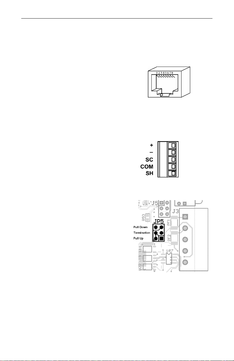
Figure 2 — EIA-485 Connector
Figure 1 — RJ-45 Jack
Figure 3 — EIA-485 Jumpers
Environmental
Operating temperature: 0°C to +60°C
Storage temperature: –40°C to +85°C
Humidity: 10% to 95%, non-condensing
Ethernet Connector Pin Assignments
1 TD+ 3 RD+
2 TD– 6 RD–
(All other pins are unused.)
USB Port USB 2.0, Type A
This connector is for future use.
EIA-485 Connector Pin Assignments
+ Signal High
– Signal Low
SC Signal Common
COM 0V
SH Shield (Chassis)
EIA-485 Bias and Termination Jumpers
Install:
upper jumper for pull-down bias
lower jumper for pull-up bias
middle jumper to terminate bus
TD120100-0IC
4
Page 5

Mechanical
Figure 4 — BASrouterLX Dimensional Drawing
TD120100-0IC
5
Page 6

POWER
The BASrouterLX requires 24 VAC or 24 VDC and draws a commensurate
amount of current. The recommended conductor size is 16–18 AWG. COM is
directly connected to zero volts and the chassis is DC isolated from zero volts.
Input connections are reverse-polarity protected.
Figure 5 — Power Options
WARNING: Powering devices can present hazards. Read the following carefully.
Since the product incorporates a half-wave rectifier circuit, it can share the same
24 VAC power with other half-wave rectified devices. It can also be powered
from a 24 VDC source. A redundant power connection exists for back-up power
schemes.
The product incorporates a 3-wire optically-isolated EIA-485 interface for the
serial connection, allowing better circuit protection and noise immunity. To
connect to other 3-wire devices simply make a one-to-one connection to the other
devices. But when connecting to 2-wire non-isolated devices, the signal common
(SC) on the product must share the reference used by the 2-wire devices. This is
accomplished by tying the SC pin to COM on the product and by grounding the
low-side of each power supply on all connected devices. In this way all EIA-485
transceivers share the same earth reference. Notice that the SC pin is signal
common and not a shield pin. For shield connections, use the SH pin. Far-end
external termination is required as shown. Near-end bias and termination are
internally supplied within the product.
TD120100-0IC
6
Page 7

For devices that share a power source with our product, see Figure 6 for proper 2wire bus connections and Figure 7 for proper 3-wire bus connections.
Figure 6 — 2-wire EIA-485 Bus with Shared Power Source
Figure 7 — 3-wire EIA-485 Bus with Shared Power Source
TD120100-0IC
7
Page 8

For devices that do not share power with our product, see Figure 8 for proper 2wire bus connections and Figure 9 for proper 3-wire bus connections.
Figure 8 — 2-wire EIA-485 Bus with Separate Power Sources
Figure 9 — 3-wire EIA-485 Bus with Separate Power Sources
TD120100-0IC
8
Page 9

Function
Signalling &
Data Rate
Minimum Required
Cable
Maximum
Segment Distance
Ethernet
10BASE-T
10 Mbps
Category 3 UTP
100 m (328 ft)
Ethernet
100BASE-TX
100 Mbps
Category 5 UTP
100 m (328 ft)
MS/TP
9.6–115.2 kbps
Belden® 9841, 3106A, 9842
As detailed on page 3.
Limited Power Sources
The router should be powered by a limited power source complying with the
requirements of the National Electric Code (NEC) article 725 or other
international codes meeting the same intent of limiting the amount of power of
the source. Under NEC article 725, a Class 2 circuit is that portion of the wiring
system between the load side of a Class 2 power source and the connected
equipment. For AC or DC voltages up to 30 volts, the power rating of a Class 2
power source is limited to 100 VA. The transformer or power supply complying
with the Class 2 rating must carry a corresponding listing from a regulatory
agency such as Underwriters Laboratories (UL).
LEDS
Power This LED is green if power supplied to the unit is proper.
Ethernet L glows green for a proper 100 Mbps link and yellow for a proper 10
Mbps link. It flashes to show activity.
D glows green for a full-duplex link and is off for a half-duplex link
EIA-485 Tx flashes green when transmitting valid EIA-485 traffic.
Rx flashes green when receiving valid EIA-485 traffic.
RESET SWITCH
To reset the router to its default values (except for configuration settings), use a
paperclip or similar tool to press the Reset IP button for at least 3 seconds while
the router is powered. Then release the reset button and remove power from the
router for 3 seconds. Restore power and the unit will now use default IP values
and User ID/Password which are admin/admin.
CABLING CONSIDERATIONS
When attaching cables to the unit, Table 1 should be considered.
Table 1 — Cabling Considerations
TD120100-0IC
9
Page 10

NOTE: If using shielded cable, connect to chassis at only one point. Wire size
may be dictated by electrical codes for the area where the equipment is being
installed. Consult local regulations.
Observe in Table 1 that 10BASE-T segments can successfully use Category 3, 4
or 5 cable — however, 100BASE-TX segments must use Category 5 cable.
Category 5e cable is highly recommended as the minimum for new installations.
The Ethernet port of the router employs Auto-MDIX technology so either straightthrough or crossover cables can be used to connect to the network.
MS/TP PORT
This port uses an isolated EIA-485 transceiver connected to a 5-pin removable
connector. The transceiver + and – lines tie to + and – pins of the connector. The
SC pin ties to the transceiver ground. You MUST connect the SC pin to the
MS/TP segment signal common — or EIA-485 communication will fail!
In Figure 10 a simplified schematic of the isolated EIA-485 transceiver is shown.
Notice that the transceiver common (SC) is electrically isolated from the router
power supply common (COM) through the use of opto-isolators and an isolated
DC-DC converter. An isolated EIA-485 transceiver offers less chance of damage
to the transceiver from high common-mode voltages, but there is still a risk. Surge
suppression is applied between the two differential inputs and between each input
and ground. Since the transceiver is electrically isolated, the transceiver circuit
common must be brought out for connection to the other devices on the EIA-485
network. This is accomplished by pin SC. The differential pair is labelled + and
– and requires a three-wire connection to the EIA-485 network. Connecting other
isolated EIA-485 devices is no problem since each device requires a 3-wire
connection. Just make corresponding connections. For non-isolated EIA-485
devices, usually only a 2-wire connection is provided. The third wire is the power
supply common. In this situation, the SC connection MUST be made to the power
supply common of the non-isolated device. Refer to the device vendor
instructions for connecting such a device.
In an application where one connection is made to Ethernet and the other to EIA485, the location of the router is probably at the end of the EIA-485 bus segment
and therefore both bias and termination must be applied to the segment end. The
product is shipped with bias and termination applied, but this can be changed by
removing three jumpers. This should be done if the router is to be connected
anywhere between the end EIA-485 devices.
The router can address up to 31 MS/TP full-load or 62 half-load devices on the
local bus at baud rates from 9.6 to 115.2 kbps.
EIA-485 Bias and Termination Jumpers
TD120100-0IC
10
Page 11

After removing the router cover, three jumpers are accessible on a 6-pin jumper
block located near the EIA-485 connector. These impart 604 Ω of bias via the upper
jumper (pull-up) and the lower jumper (pull-down), and 130 Ω of termination
impedance with the middle jumper. With all three jumpers in place, the effective
termination resistance is 120 Ω — consistent with the MS/TP standard. If the
router is not installed at the end of a segment, remove all the jumpers and install
120 Ω at each far end of the bus.
Figure 10 — Internal Termination and Bias
TD120100-0IC
11
Page 12

NEED MORE HELP INSTALLING THIS PRODUCT?
The product features embedded help which can be useful during installation.
When contacting one of our offices, just ask for Technical Support. More
information can be found at:
www.ccontrols.com/support/basrouterlx.htm
WARRANTY
Contemporary Controls (CC) warrants its new product to the original purchaser for two
years from the product shipping date. Product returned to CC for repair is warranted
for one year from the date that the repaired product is shipped back to the purchaser or
for the remainder of the original warranty period, whichever is longer.
If a CC product fails to operate in compliance with its specification during the
warranty period, CC will, at its option, repair or replace the product at no charge. The
customer is, however, responsible for shipping the product; CC assumes no
responsibility for the product until it is received.
CC’s limited warranty covers products only as delivered and does not cover repair of
products that have been damaged by abuse, accident, disaster, misuse, or incorrect
installation. User modification may void the warranty if the product is damaged by the
modification, in which case this warranty does not cover repair or replacement.
This warranty in no way warrants suitability of the product for any specific
application. IN NO EVENT WILL CC BE LIABLE FOR ANY DAMAGES
INCLUDING LOST PROFITS, LOST SAVINGS, OR OTHER INCIDENTAL OR
CONSEQUENTIAL DAMAGES ARISING OUT OF THE USE OR INABILITY TO
USE THE PRODUCT EVEN IF CC HAS BEEN ADVISED OF THE POSSIBILITY
OF SUCH DAMAGES, OR FOR ANY CLAIM BY ANY PARTY OTHER THAN
THE PURCHASER.
THE ABOVE WARRANTY IS IN LIEU OF ANY AND ALL OTHER
WARRANTIES, EXPRESSED OR IMPLIED OR STATUTORY, INCLUDING
THE WARRANTIES OF MERCHANTABILITY, FITNESS FOR PARTICULAR
PURPOSE OR USE, TITLE AND NONINFRINGEMENT.
RETURNING PRODUCTS FOR REPAIR
Return the product to the location where it was purchased by following the
instructions at the URL below:
www.ccontrols.com/rma.htm
DECLARATION OF CONFORMITY
Information about regulatory compliance can be found at the URL below:
www.ccontrols.com/compliance.htm
December 2013
TD120100-0IC
12
 Loading...