

Page 1

AI-FR
Fixed Port Active Hubs for Redundant Fiber Ring Topology in
ARCNET
INTRODUCTION
Traditionally, ARCNET has been cabled as either a star or bus network, but
never as a ring. However, under certain conditions a ring topology is
possible. The ring has merit when the goal is to provide redundant cabling
so that continuity can be preserved in the event of cable failure. If one cable
becomes disabled for any reason, another is still available to pass messages.
It is for this purpose that the AI-FR has been developed and implemented to
achieve fiber optic redundancy in an otherwise un-redundant networking
technology.
The AI-FR utilizes the same robust hub timing electronics found in
Contemporary Controls’ MOD HUB series of modular active hubs. This
includes precision delay line timing, digitally controlled for dependable
operation and reduced bit jitter.
The AI-FR is an application specific active hub that provides integrity status
of the redundant fiber backbone. Redundant network topology — defined as
a fiber optic ring with a local drop — is ideally established with three-port
hubs, each incorporating the principle of fault monitoring.
A fiber backbone ring up to 2 km in size and employing up to four AI-FR
hubs is possible. By decreasing the total fiber ring size, additional AI-FR
hubs can be attached to the network allowing more devices to share the
redundant ring.
Local Area Networks
INST ALLA TION GUIDE
The AI-FR operates from either low voltage AC or DC power. For DC
operation, a voltage source in the range of 10 to 36 volts is required. For
AC operation, the source must be in the range of 8 to 24 volts. Redundant
power supplies can be attached for critical applications.
The hub is available in two versions. The AI-FR/CXB hub provides fiber
ring continuity with a coaxial bus local drop while the AI-FR/TB5
accommodates a drop established by twisted-pair bus.
Page 2
SPECIFICATIONS
Electrical DC AC
Input voltage: 10–36 V
Input power: 4 W 4 VA
Input frequency: N/A 47–63 Hz
Fault Relay Contacts
Max current and voltage: 500 mA
Environmental
Operating temperature: 0°C to +60°C
Storage temperature:
Data Rate
AI-FR hubs operate at 2.5 Mbps.
Timing
AI-FR delay time: 330 ns maximum at 2.5 Mbps
Unlatch delay time: 11.9 µs at 2.5 Mbps
Optical Power Budget (-FOG 850 nm at 25°C)
50/125 microns 6.6 dB
62.5/125 microns 10.4 dB
100/140 microns 15.9 dB
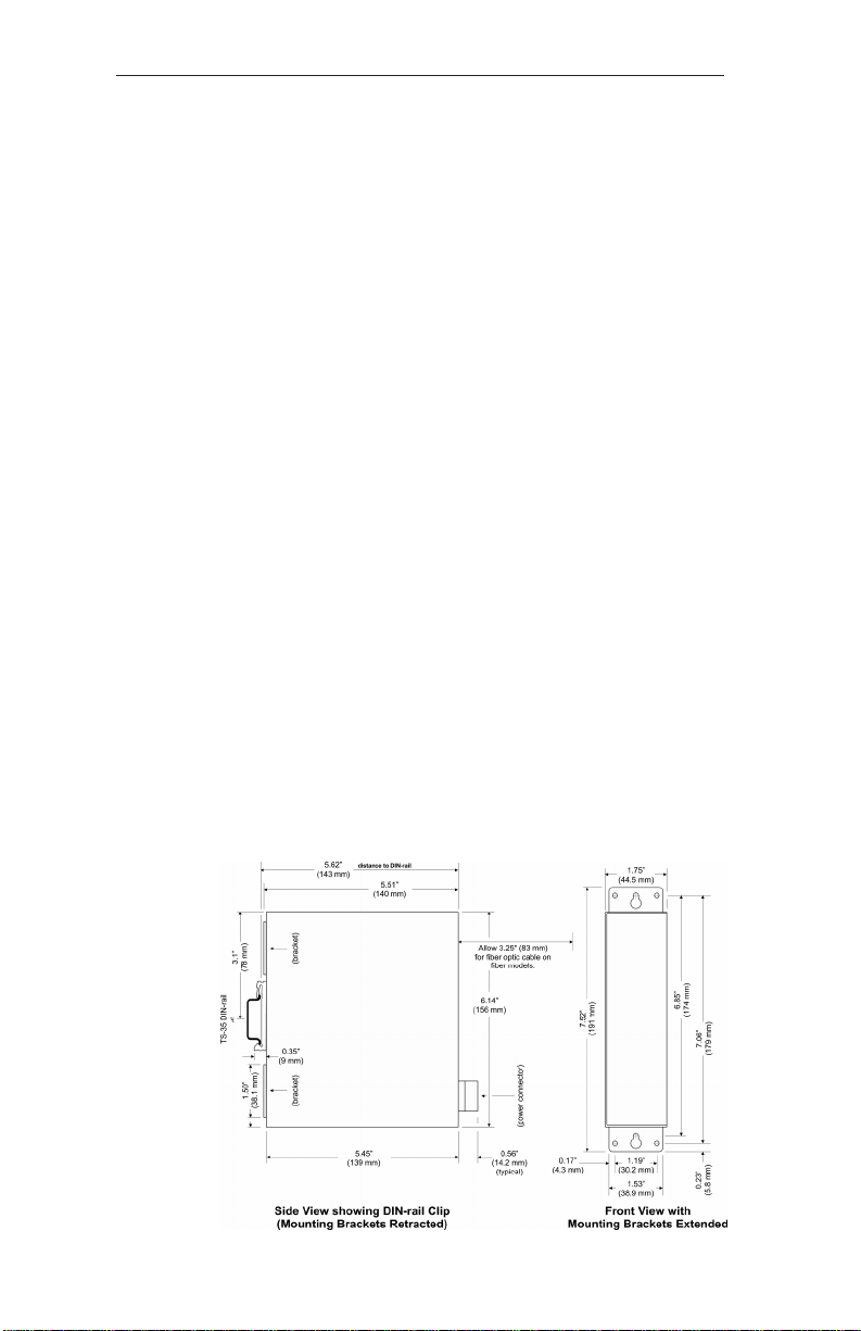
Dimensions Compatibility
5.45" x 6.14" (139 mm x 156 mm) Compliant with ANSI/ATA 878.1
–40°C to +85°C
8–24 V
200 V
Shipping Weight Regulatory Compliance
2lbs. (.9kg) CE Mark
CFR 47, Part 15 Class A
Mechanical
TD675300-0ID
2
Page 3
INSTALLATION
AI-FR hubs are intended to be panel mounted in an industrial enclosure or
wiring closet with two #8 pan head screws (not provided). Optionally, a
DIN rail mount can be used by purchasing a DIN rail mounting kit.
Electromagnetic Compliance
This equipment is intended for nonresidential use. Operation in a residential
area is likely to generate electrical interference unless corrective measures
are undertaken by the user.
Powering
AI-FR hubs require either low voltage AC or DC power via a four-pin
removable keyed connector. Consult the specifications for power
requirements. The various power options are explained below.
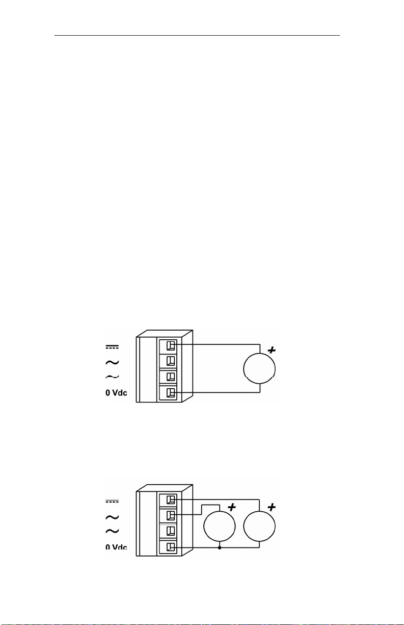
DC Powered
AI-FR hubs accept a voltage range of 10–36 VDC and draw a current value
commensurate with 4-watt power consumption. Power conductors should be
sized accordingly. Ground is directly connected to zero volts and the
equipment chassis is isolated from zero volts. The input connections are
reverse-polarity protected.
Figure 1 — DC Powered
Redundant DC Powered
Redundant diode-isolated DC power inputs are provided so the AI-FR can
operate despite the loss of primary power. Either source must provide
4 watts, but the currents drawn from the two supplies may differ.
Figure 2 — Redundant DC Powered
TD675300-0ID
3
Page 4

AC Powered
The AI-FR can be powered by an AC voltage in the range of 8–24VAC
capable of delivering 4 VA of apparent power. Two auxiliary power supplies
are available: The AI-XFMR is for a 120 VAC. The AI-XFMR-E is for
230 VAC.
Figure 3 — AC Powered
Figure 4 — AC Powered with Grounded Secondar y
AC Powered with Battery Backup
The AI-FR can also operate in the AC mode with a backup battery providing
power if the AC source fails. The AI-FR does NOT charge the battery so
separate provisions are required for charging.
Figure 5 — AC Powered with Battery Backup
TD675300-0ID
4
Page 5

Connecting Cables
Each AI-FR hub provides fiber ring continuity with either a coaxial bus
(/CXB) or twisted-pair bus (/TB5) local drop.
Connecting the Fiber Optic Cable
Bayonet-locking-style ST connectors (mechanically similar to BNC coaxial
cable connectors) are provided for attaching fiber optic cable (typically
multimode) of 50/125, 62.5/125, or 100/140 in size.
Connecting Coaxial Cable Bus Networks (-CXB)
The AI-FR/CXB allows RG-62/u coaxial cabling to various nodes via BNC
“T” connectors at each device. Each end of a segment must be terminated
with 93 ohms of passive resistance using a BNC terminator (BNC-TER). If
the AI-FR occupies one end of the bus, it also must have the added
termination. Make sure that all devices are -CXB compliant.
Connecting Shielded Twisted-Pair Bus Networks (-TB5)
The AI-FR/TB5 has dual RJ-45 connectors for communication with various
nodes via shielded twisted-pair cable. Each end of a segment must be
terminated with 100 ohms of passive resistance using a TB5 terminator
(TB5-TER). If the AI-FR occupies one end of the bus, it also must have the
added termination.
Determining Maximum Ring Length for the AI-FR/TB5
Formula: Max Ring Length =
Table: Max Ring Length versus Hub Count
Number of Max Ring
Hubs Length
2 2248
3 2182
42116
5 2050
6 1984
7 1918
8 1852
9 1786
10 1720
11.9 µs – (Number of Hubs • 330 ns)
TD675300-0ID
5
5 ns
Page 6

OPERATION
In IDLE state, the AI-FR hub awaits an ARCNET signal with all its
receivers enabled and all transmitters disabled. As soon as one of its ports
senses a signal, the hub becomes ACTIVE, thus keeping that receiving port
enabled while disabling all other receivers. Conversely, all hub transmitters
are enabled except that of the receiving port.
The unlatch delay (which squelches any recirculating message) has been
increased from 5.9 µs to 11.9 µs. Hence, total delay due to fiber
propagation (5 ns/m) and the number of AI-FR hubs (330 ns/hub) must be
less than 11.9 µs. After 11.9 µs have elapsed without a logic “1” being
received, the hub assumes the source has finished transmitting. The hub
then “unlatches,” switching from the ACTIVE to the IDLE state.
With a fiber ring properly configured, activity will be present on both
backbone ports. The AI-FR will latch the first active port and block the
other. If both ports receive simultaneous data, priority is given to port 2.
Fault Monitoring
If something disrupts normal operation, a watchdog timer (sensing no hub
activity after a preset time) automatically resets its timing circuitry to ensure
that the hub reestablishes communication.
If a fiber fails, the AI-FR will sense no activity within 250 ms and open the
screw terminals of the front-panel relay connection (refer to figure 6 below).
By monitoring these terminals, fiber faults can be detected. If the hub locks
on one port for more than 1.2 seconds (possibly due to circulating noise), a
second watchdog timer interprets this as a lockup, clears the hub and
restores normal operation.
Figure 6 — Fiber Ring Field Connections
TD675300-0ID
6
Page 7

LED Indicators
There are several LEDs on the AI-FR which indicate network operation and
help problem diagnosis:
ACITIVITY LEDs 1, 2 and 3
Just above the local drop connectors are three numbered LEDs which
indicate ARCNET traffic is being received on the respective ports. (Port
transmissions do not light any LEDs.) The brighter the LED, the greater its
port traffic.
STATUS (green) Properly powered and connected but with no valid ARCNET activity on any
port, this LED will flash at a periodic rate in the idle condition. When lit
continuously, this LED indicates that ARCNET traffic is being received and
faithfully regenerated to the other ports on the hub. RECON (yellow)
As nodes enter or leave the network, this LED will flash to report a routine
reconfiguration of the network. Reconfigurations are not sensed, but
assumed when no data has occurred for 82 ms. Reconfiguration takes a
fraction of a second, but the LED glows for one second for ease of viewing.
Occasional flashes are normal as automatic reconfigurations take place, but
a constant or frequently flashing LED could indicate a faulty network
interface module; defective cable; duplicate node IDs; or excessive electrical
interference.
Troubleshooting with LEDS
ACTIVITY LED fails to light: This may indicate the cable is disconnected
or open, the cable is attached to a defective node, or the hub port is bad.
Test the hub port by swapping its cable with another cable attached to a port
known to function properly. If the symptom follows the cable, the port is
good and a node or cable problem is indicated.
ACTIVITY LED glows excessively: A “chattering node” (one with a
defective receiver) causes continuous reconfigurations. The AI-FR indicates
a bad node by a bright ACTIVITY LED (other port ACTIVITY LEDs will
be dim) and a constantly lit RECON LED. Detaching the cable associated
with the bright LED will extinguish the RECON LED and return other port
ACTIVITY LEDs to normal brightness, thereby confirming the defective
node.
STATUS LED fails to light despite receiving valid ARCNET traffic: This
indicates a defective AI-FR hub.
TD675300-0ID
7
Page 8

DECLARATION OF CONFORMITY
Applied Council Directives:
Electromagnetic Compatibility Directive, 89/336/EEC Council Directive as
amended by Council Directive 92/31/EEC & Council Directive 93/68/EEC
Standard to which Conformity is Declared
EN 55022:1995 CISPR22: 1993, Class A, Limits and Methods of
Measurement of Radio Disturbance Characteristics of Information
T echnology Equipment
EN 55024:1998, Information Technology Equipment — Immunity
Characteristics — Limits and Methods of Measurement
Manufacturer:
Contemporary Control Systems, Inc.
2431 Curtiss Street
Downers Grove, IL 60515 USA
Authorized Representative:
Contemporary Controls Ltd
Sovereign Court Two
University of Warwick Science Park
Sir William Lyons Road
Coventry CV4 7EZ
UNITED KINGDOM
T ype of Equipment:
Industrial local area network fiber-ring hub
Model Directive
EMC
AI-FR/CXB Yes
AI-FR/TB5 Yes
Manufacturer’s Declaration: I, the undersigned, hereby declare that the
product(s) specified above conforms to the listed directives and standards.
George M. Thomas, President September 22, 2000
TD675300-0ID
8
Page 9

NEED MORE HELP INSTALLING THIS PRODUCT?
More information can be found on our web site at www.ccontrols.com. Browse
the Technical Support section of our site for a look at our interactive on-line
technical manuals, downloadable software drivers and utility programs that can
test the product. When contacting one of our offices, ask for technical support.
Warranty
Contemporary Controls (CC) warrants its new product to the original purchaser for two years from the product shipping date. Product returned to CC
for repair is warranted for one year from the date that the repaired product is
shipped back to the purchaser or for the remainder of the original warranty
period, whichever is longer.
If a CC product fails to operate in compliance with its specification during the
warranty period, CC will, at its option, repair or replace the product at no
charge. The customer is, however, responsible for shipping the product; CC
assumes no responsibility for the product until it is received.
CC’s limited warranty covers products only as delivered and does not cover
repair of products that have been damaged by abuse, accident, disaster, misuse, or incorrect installation. User modification may void the warranty if the
product is damaged by the modification, in which case this warranty does not
cover repair or replacement.
This warranty in no way warrants suitability of the product for any specific
application. IN NO EVENT WILL CC BE LIABLE FOR ANY DAMAGES
INCLUDING LOST PROFITS, LOST SAVINGS, OR OTHER INCIDENTAL
OR CONSEQUENTIAL DAMAGES ARISING OUT OF THE USE OR
INABILITY TO USE THE PRODUCT EVEN IF CC HAS BEEN ADVISED
OF THE POSSIBILITY OF SUCH DAMAGES, OR FOR ANY CLAIM BY
ANY PARTY OTHER THAN THE PURCHASER.
THE ABOVE WARRANTY IS IN LIEU OF ANY AND ALL OTHER
WARRANTIES, EXPRESSED OR IMPLIED OR STATUTORY, INCLUDING THE WARRANTIES OF MERCHANTABILITY, FITNESS FOR
PARTICULAR PURPOSE OR USE, TITLE AND NONINFRINGEMENT.
Returning Products for Repair
Before returning a product for repair, contact Customer Service. A
representative will instruct you on our returns procedure.
Contemporary Control Systems, Inc.
2431 Curtiss Street
Downers Grove, Illinois 60515 USA
Tel: +1-630-963-7070
Fax: +1-630-963-0109
E-mail: info@ccontrols.com
WWW: http://www.ccontrols.com
Contemporary Controls Ltd
Sovereign Court Two
University of Warwick Science Park
Sir William Lyons Road
Coventry CV4 7EZ UK
Tel: +44 (0)24 7641 3786
Fax: +44 (0)24 7641 3923
E-mail: info@ccontrols.co.uk
TD675300-0ID
9
 Loading...