

Contemporary Controls BAST-221C, BASstat 221C-B2, BASstat Series, BASstat 221C-BW2 User Manual
Page 1
BAST-221C
BACnet Communicating Thermostat for Multi-Stage Relay Heating/Cooling/Ventilation
BASstat
Binary (B2-BW2) User Manual
# UM-15090000-AA4
Page 2

Trademarks
Contemporary Control Systems, Inc.
Tel:
+1-630-963-7070
2431 Curtiss Street
Fax:
+1-630-963-0109
Downers Grove, Illinois 60515 USA
E-mail:
info@ccontrols.com
Contemporary Controls Ltd
Tel:
+44 (0)24 7641 3786
14 Bow Court
Fax:
+44 (0)24 7641 3923
Fletchworth Gate
E-mail:
info@ccontrols.co.uk
Coventry CV5 6SP UK
Contemporary Controls (Suzhou) Co.
Tel:
+44 (0)24 7641 3786
11 Huoju Road
Fax:
+44 (0)24 7641 3923
Industrial Park — Science &
E-mail:
info@ccontrols.com.cn
New District, Suzhou
Contemporary Controls GmbH
Tel:
+49 (0)341 520359 0
Fuggerstraße 1 B
Fax:
+49 (0)341 520359 16
D-04158 Leipzig Deutschland
E-mail:
info@ccontrols.de
BASautomation, Contemporary Controls, and CTRLink are registered trademarks of
Contemporary Control Systems, Inc. BACnet is a registered trademark of the American Society
of Heating, Refrigerating and Air-Conditioning Engineers, Inc. Powered by Sedona Framework
is a trademark of Tridium, Inc. Other product names may be trademarks or registered
trademarks of their respective companies.
Copyright
© Copyright 2018, by Contemporary Control Systems, Inc. All rights reserved. No part of this
publication may be reproduced, transmitted, transcribed, stored in a retrieval system, or
translated into any language or computer language, in any form or by any means, electronic,
mechanical, magnetic, optical, chemical, manual, or otherwise, without the prior written
permission of:
Ltd
Technology
PR China 215009
Disclaimer
Contemporary Control Systems, Inc. reserves the right to make changes in the specifications of
the product described within this manual at any time without notice and without obligation of
Contemporary Control Systems, Inc. to notify any person of such revision or change.
UM-15090000-AA4 Page 2
Page 3

Contents
1 Introduction .............................................................................................................. 4
1.1 Features and Benefits ........................................................................................ 4
1.2 Product Image and Main Features ..................................................................... 6
2 Specifications ........................................................................................................... 7
2.1 Inputs ................................................................................................................. 7
2.2 Outputs .............................................................................................................. 7
2.3 Communication .................................................................................................. 7
2.4 Electrical ............................................................................................................ 7
2.5 Environmental .................................................................................................... 8
2.6 Electromagnetic Compatibility ............................................................................ 8
2.7 Mechanical (all dimensions are in mm) .............................................................. 9
3 Installation .............................................................................................................. 11
3.1 Terminal Block Pin Assignments ...................................................................... 11
3.2 Limited Power Source ...................................................................................... 12
3.3 Power Supply Precautions ............................................................................... 13
3.4 Wiring Diagram ................................................................................................ 13
4 Operation ............................................................................................................... 14
4.1 User Mode........................................................................................................ 14
4.2 Control Type..................................................................................................... 16
4.3 Engineering Mode Menu .................................................................................. 20
4.4 BACnet Objects and Network Configuration .................................................... 30
5 Warranty ................................................................................................................ 52
6 Returning Products for Repair ................................................................................ 53
7 Declaration of Conformity ....................................................................................... 54
UM-15090000-AA4 Page 3
Page 4

1 Introduction
The BAST-221C is a member of the BASstat BACnet Communicating Thermostat series. It
provides multi-stage heating and cooling control in an attractive wall-mounted enclosure with a
large LCD display. Intended for use with rooftop units (RTUs), the thermostat can control one or
two stages of heating and one or two stages of Direct Expansion (DX) cooling. The BASstat is
BACnet compliant and BTL listed to ensure seamless integration into BACnet networks. There
are two models with the only difference being the way the thermostat communicates to a
BACnet client. One model (B2) is BACnet MS/TP connected and can be routed to BACnet/IP
clients using a BASrouter (BASRT-B)
be integrated into any 802.11 b/g/n Wi-Fi network. User-side comfort control is accomplished
with six buttons – Mode (Heat, Cool, or Ventilation), Fan, Raise (Up Arrow), Lower (Down
Arrow), Set, and Power. There also are options to lock select buttons or all buttons on the
thermostat. A large and easy to read LCD display indicates setpoint, space temperature and
current mode of operation using graphical icons.
The BASstat has a built-in space temperature sensor with provision for remote wired 3kΩ NTC
thermistor sensor or temperature value can be sent by another communicating device over the
BACnet network. Both models have five relays – two for stage heating, two for stage cooling
and one for fan. The BASstat is configurable using its buttons and entering the Engineering
Menu or via a network connection to a BACnet client. Contemporary Controls’ free
Discovery Tool can be used for initial discovery and configuration of the thermostat over
BACnet. Control algorithm parameters such as deadband, proportional gain, integral rate, stage
trip points and stage widths are all configurable. The BASstat also features configurable shortcycle protection, maximum cycles per hour, fan control and occupancy selection. All states and
pending delays are indicated by graphical icons on the thermostat display.
The numerous features available in the BASstat can be configured by the systems integrator to
meet user requirements in two different ways. One way is using a button sequence on the
thermostat in order to enter the Engineering Menu - which requires physical access to the
thermostat. Optionally, the buttons could be locked to limit user access to Engineering Menu
after installation is complete. The second method is configuring the thermostat over the BACnet
network using a BACnet client device or software such as Contemporary Controls’ free
Discovery Tool (BDT). All features available are configurable using both methods.
. The other model, (BW2) is BACnet/IP over Wi-Fi and can
BACnet
BACnet
1.1 Features and Benefits
• Fully stand-alone thermostat algorithm or fully BACnet network-controllable
• BTL listed with B-ASC device profile for seamless integration into BACnet networks
• 24VAC (+/-10%) power input
• Manual-changeover or Auto-changeover control types
• Two models of thermostats for BACnet communication options:
-B2 model - BACnet MS/TP with baud rate selections up to 76.8kbps
-BW2 model -BACnet/IP over Wi-Fi model can be integrated into any 802.11 b/g/n Wi-Fi
network
• Suitable for single to multi-stage heat/cool control applications with manual or automatic
changeover between heating and cooling modes
UM-15090000-AA4 Page 4
Page 5

• Adjustable algorithm applied to multi-stage step control
• Adjustable minimum on/off time staging for optimizing runtime
• Effective run time accumulation for system runtime for energy consumption metering
• Full configurable control parameters such as deadband, proportional gain, integral rate,
stage trip points, and cycle time
• Adjustable minimum/maximum set point ranges
• Three options for temperature reading:
-Built-in temperature sensor, or
-Remote sensor (RS) input for wiring in a remote temperature sensor (NTC 3kΩ), or
-BACnet network temperature override
• Occupancy status can be switched from thermostat buttons by occupants or using
BACnet network command.
• Separate adjustable occupied set points for heating and cooling mode
• Separate adjustable unoccupied set points for heating and cooling mode
• Fan can be set to run continuously or automatically depending upon fan mode
• Non-volatile memory (EEPROM) retains user settings during power outage
• Thermostat buttons are selectively lockable to prevent unauthorized control
• °C or °F display
• Control outputs disabled during “OFF” state for safety
UM-15090000-AA4 Page 5
Page 6
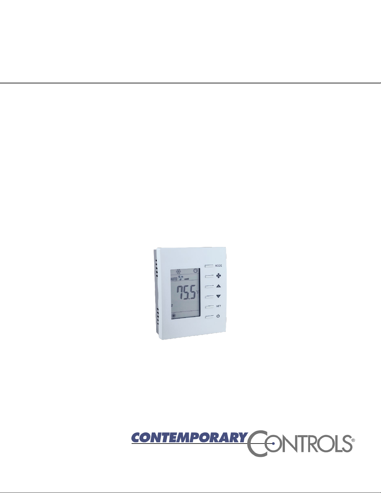
1.2 Product Image and Main Features
BASstat 221C-B2 and BASstat 221C-BW2
UM-15090000-AA4 Page 6
Page 7

2 Specifications
Item
Description
Temperature Display Range
14 to 140°F (-10 to 60°C)
Temperature Display Resolution
0.1°F (0.1°C)
Temperature Accuracy
±1.8°F (±1.0°C) with all outputs off
Setpoint Range
32-122°F (0-60°C) in 0.5° (°F or °C) increments
Remote Temperature Sensor
Provision for NTC Type 3kΩ thermistor
Item
Description
Relay Outputs
Heating 1, Heating 2, Cooling 1, Cooling 2, Fan
Contact Rating
SPST 2A at 30 VAC with inductive load
Minimum contact life
100,000 cycles
Item
Description
Protocol Compliance
BACnet MS/TP or BACnet/IP with B-ASC, BTL Listed
Physical Layer
2-wire, non-isolated EIA-485, no built-in EOL termination
Baud Rate
9.6, 19.2, 38.4, 76.8 kbps (default 38.4 kbps), N81 format
Cabling
Single-pair twisted 24GA with shield
Item
Description
Supply Voltage and Current
24 VAC (±10%) 5 VA
Power Source Class
NFPA 70 (NEC) Article 725 Part III Class 2
Internal Power Supply
Half-wave rectified and filtered DC
2.1 Inputs
2.2 Outputs
2.3 Communication
2.4 Electrical
UM-15090000-AA4 Page 7
Page 8

2.5 Environmental
Item
Description
Operating Temperature
32°F to 122°F (0 to 50°C)
Storage Temperature
-40°F to +85°F (-40°C to 30°C)
Relative Humidity
5 to 95% non-condensing
Standard
Test Method
Description
EN 61000-6-2
IEC 61000-4-2
Electrostatic Discharge Immunity
EN 61000-6-2
IEC 61000-4-3
Radiated, Radio-Frequency,
EN 61000-6-2
IEC 61000-4-4
Electrical Fast Transit/Burst Immunity
EN 61000-6-2
IEC 61000-4-5
Voltage Surge Immunity
EN 61000-6-2
IEC 61000-4-6
Immunity to Conducted Disturbances
EN 61000-6-2
IEC 61000-4-8
Power Frequency Magnetic Field
EN 61000-6-2
IEC 61000-4-11
Voltage Dips and Interruptions
EN 61000-6-3
IEC 61000-3-2
Limits for Harmonic Current Emissions
EN 61000-6-3
IEC 61000-3-3
Limitation of Voltage Fluctuations and
2.6 Electromagnetic Compatibility
The BAST-221C complies with the following specifications and bears the CE mark in
accordance with the provisions of the Electromagnetic Compatibility (EMC) Directive
2004/108/EC based on the following specifications:
Electromagnetic Field Immunity
Immunity
Flicker in Low Voltage Supply Systems
UM-15090000-AA4 Page 8
Page 9
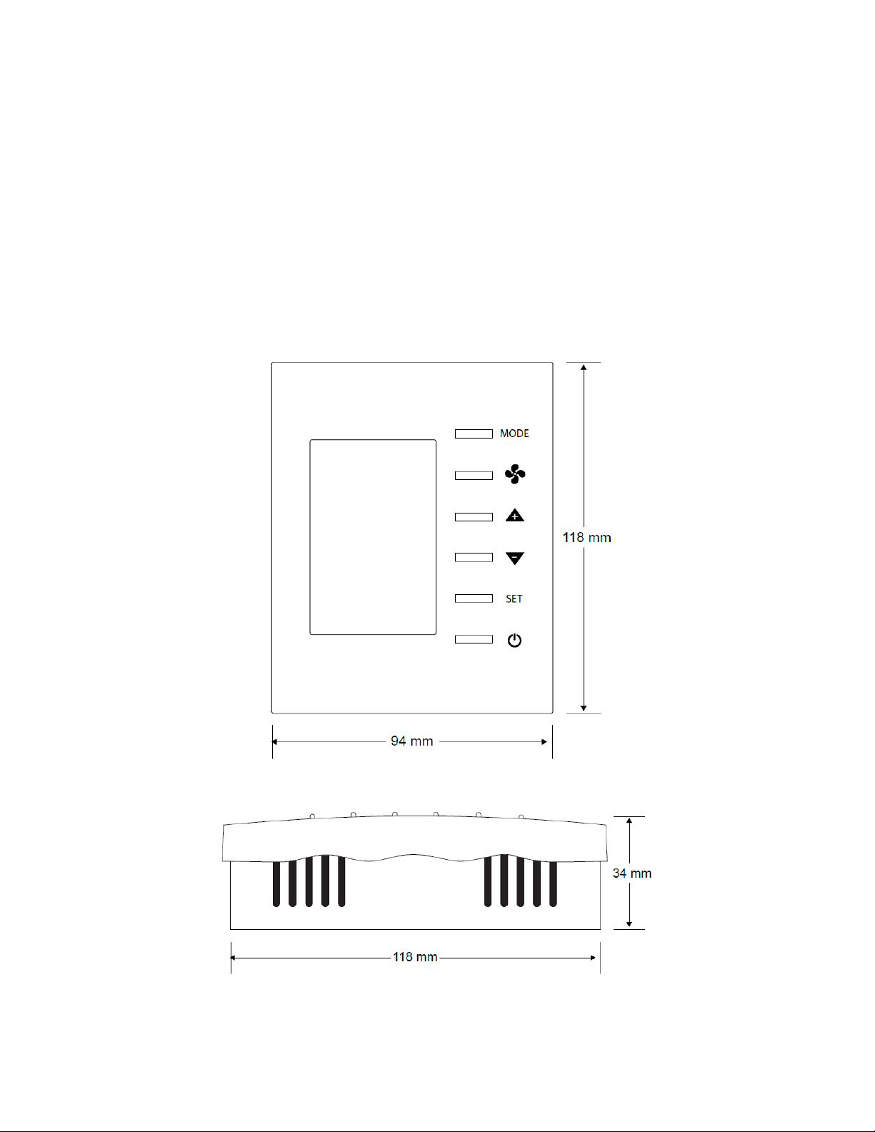
2.7 Mechanical (all dimensions are in mm)
Mounts directly onto wall, panel, standard 65×65mm junction box (hole pitch 60 mm) or
standard 2×4-inch vertical junction box (hole pitch 83.5mm)
Width: 94mm
Height: 118mm
Depth: 34mm
UM-15090000-AA4 Page 9
Page 10
UM-15090000-AA4 Page 10
Page 11

3 Installation
Number
Mark
Comment
Number
Mark
Comment
1
R
24 VAC high-side
10
2
C
24 VAC common
11
3
Y1
Cooling Stage 1
12
4
13
RS
Remote Sensor Input
5
Y2
Cooling Stage 2
14
GND
Ground
6
W1
Heating Stage 1
15
7
W2
Heating Stage 2
16
D+
BACnet MS/TP Data +
8
G
Fan
17
D-
BACnet MS/TP Data -
9
18
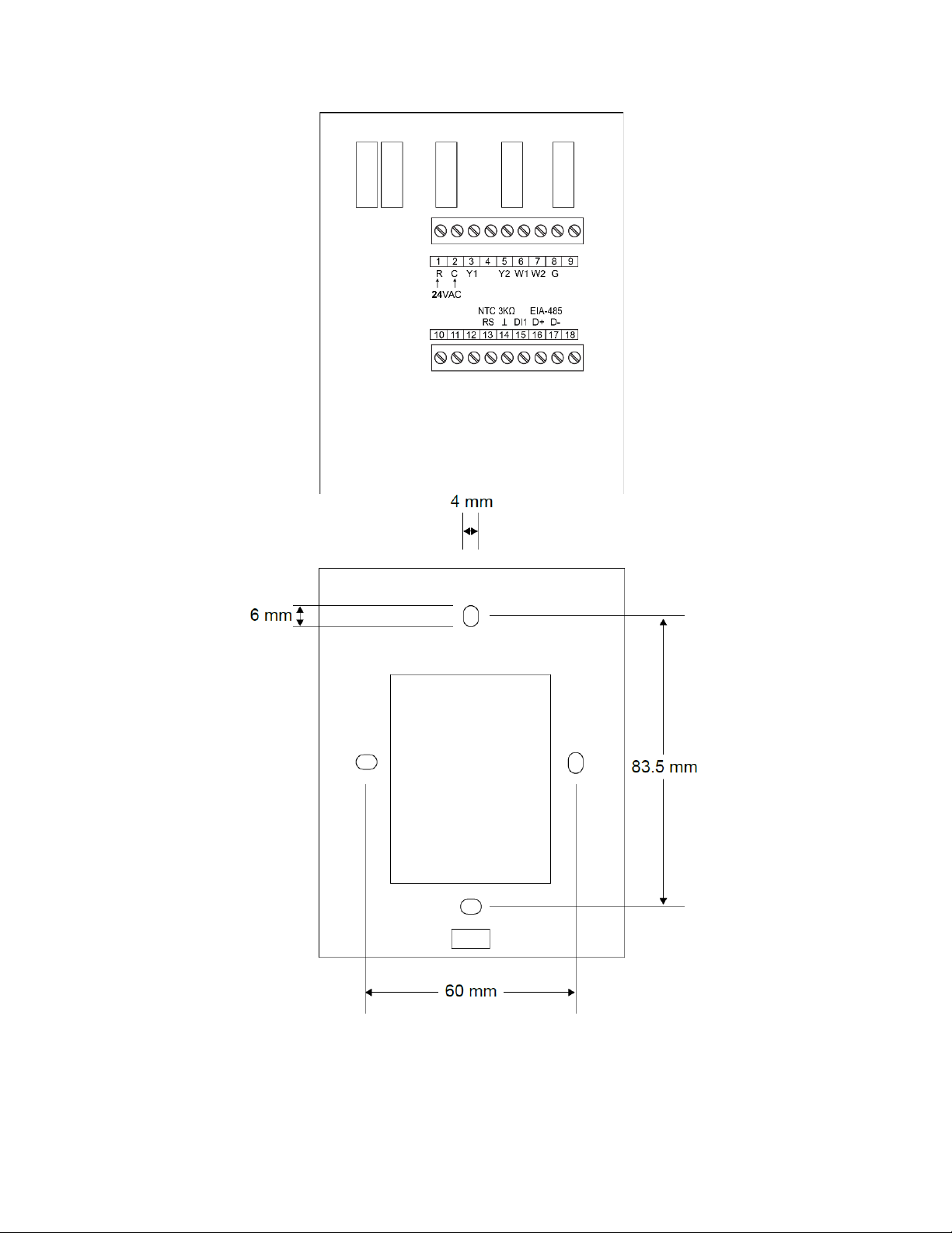
The BASstat is intended for surface-mount installation at eye-level on a wall, not subjected to
direct sunlight or direct air movement. The display (top half) can be removed from its base by
loosening the small Philips screw at the bottom of the display. There is no need to remove the
screw. Once the display is removed from the base, the base can be mounted onto the wall with
appropriate fasteners. The dimensions of the oval mounting holes are 4mm x 6mm allowing for
perfect fit adjustments. If a single-gang electrical junction box is to be used, the top and bottom
mounting holes will align with the screw holes in the junction box. Thanks to its EEPROM, the
BASstat will store its configuration in the event of power loss.
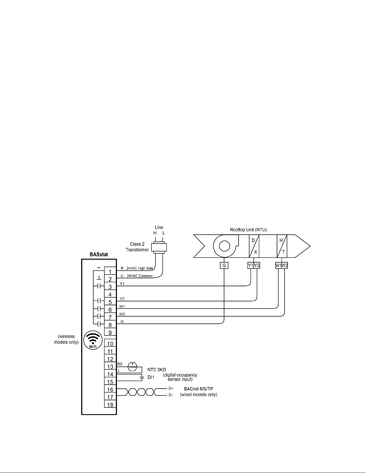
3.1 Terminal Block Pin Assignments
Two 9-pin terminal blocks provide for all field connections. Terminal markings for mechanical
equipment follow NEMA DC 3-2003 convention. For single-stage operation, connect Y wire to
Y1 and W wire to W1. BACnet MS/TP data communication connections can be found at
terminals 16 and 17 and are polarity sensitive. The BASstat (B2 MS/TP model) does not provide
End-of-Line termination. If the BASstat-B2 is the first or last device on the MS/TP bus, a
termination resistor (120Ω) must be applied across pins 16 and 17 of the input terminal. The
remote sensor input (RS) is at terminals 13 and 14. The BASstat is intended to be powered by a
Class 2 compliant power source and only accepts 24VAC.
UM-15090000-AA4 Page 11
Page 12

3.2 Limited Power Source
The BASstat thermostats accept 24VAC only with no more than 5VA of power consumption and
should be powered by a limited power source complying with the requirements of the National
Electric Code (NEC) article 725 or other international codes meeting the same intent of limiting
the amount of power of the source. Under NEC article 725, a Class 2 circuit is that portion of the
wiring system between the load side of a Class 2 power source and the connected equipment.
For AC or DC voltages up to 30 volts, the power rating of a Class 2 power source is limited to
100 VA. The transformer or power supply complying with the Class 2 rating must carry a
corresponding listing from a regulatory agency such as Underwriters Laboratories (UL).
UM-15090000-AA4 Page 12
Page 13
3.3 Power Supply Precautions
Internally, the BASstat utilizes a half-wave rectifier and therefore can share the same AC power
source with other half-wave rectified devices. Sharing AC power with full-wave rectified devices
is NOT recommended. Full-wave rectified devices usually require a dedicated AC power source
that has a secondary elevated above ground. Both secondary connections are considered HOT.
AC power sources that power several half-wave devices have a common secondary connection
called COMMON, LO, or GROUND. This connection might be tied to earth. The other side of
the secondary is considered the HOT or HI side of the connection. Connect the HOT side of the
secondary to the 24 VAC high side input on the BASstat and the LO side to 24 VAC common on
the BASstat. All other half-wave devices sharing the same AC power source need to follow the
same convention.
WARNING: Devices powered from a common AC source could be damaged if a mix of halfwave and full-wave rectified devices exist. If you are not sure of the type of rectifier used by
another device, do not share the AC source with it.
3.4 Wiring Diagram
UM-15090000-AA4 Page 13
Page 14

4 Operation
4.1 User Mode
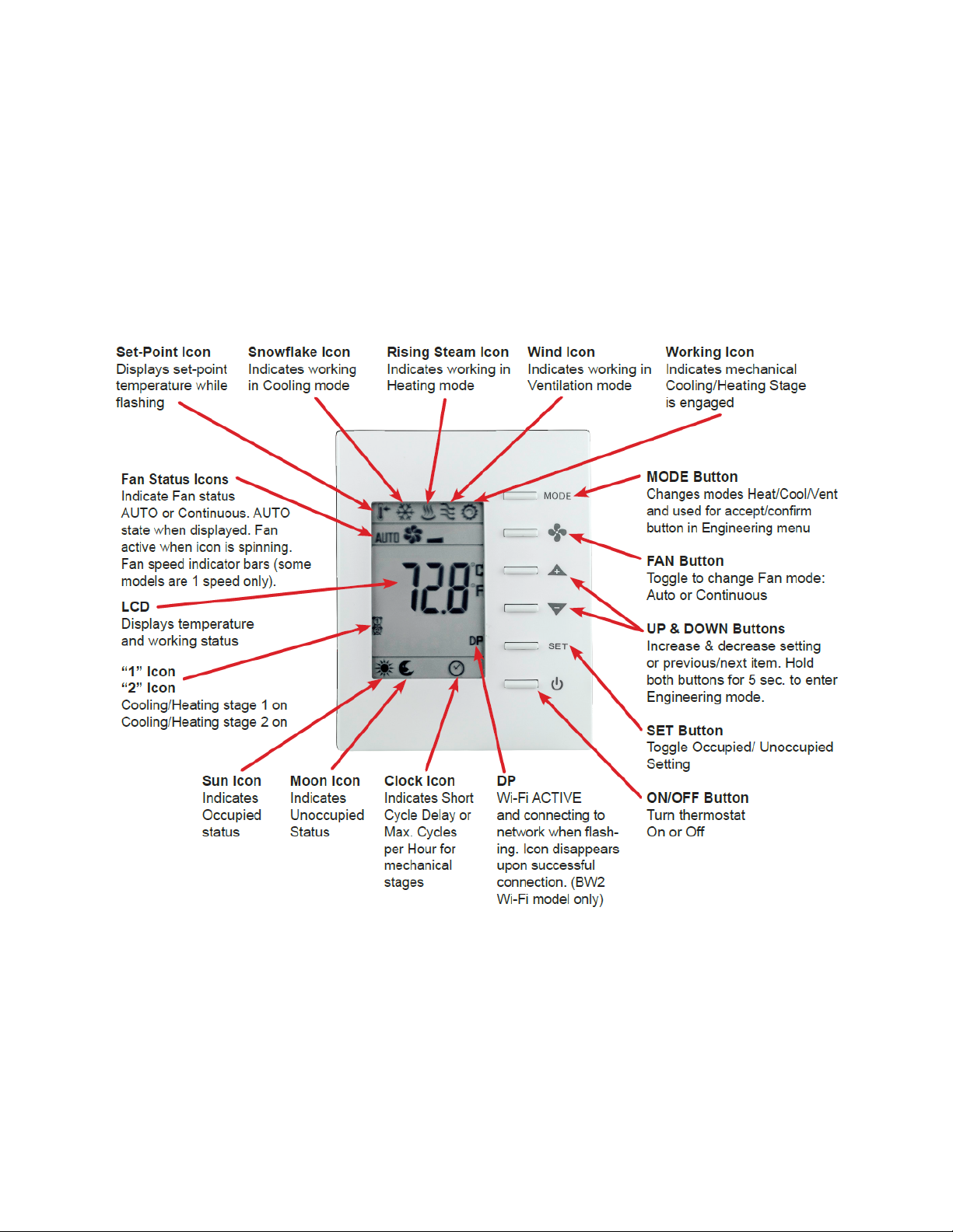
User-side comfort control is accomplished with six buttons – MODE (Heat, Cool, or Ventilate),
FAN (Auto or Continuous), UP, DOWN, SET, and POWER. There are also options to lock
select buttons or all buttons on the thermostat to limit user access if required in certain
applications. A large LCD display indicates setpoint, space temperature, occupancy status,
and current mode of operation using graphical icons.
System modes (Cool, Heat, Ventilate) available to the user are dependent on control type
chosen from Engineering Menu (tyPE) or BACnet object [MSV7] Control Type for BW2 model
and [MSV8] Control Type for B2 model. (See section 4.2 Control Type of this manual).
System modes and button operation may be limited by installation engineer, especially if the
thermostat is completely controlled over BACnet network.
The first tier of operation includes the following settings as shown below. To operate the
thermostat:
1.
The POWER button toggles between ON or OFF states to start / stop the
thermostat. This will disable control (ON/OFF control can be accomplished over BACnet
as well).
2.
At power ON, press any button to start the User Mode operation. Press the MODE
button to toggle between different HVAC operating modes such as Cool,
Heat, or Ventilate@Cool and Ventilate@Heat.
Press the UP/ DOWN buttons to increase/decrease temperature
setpoint or rotate the values of a setting. Press the FAN button to toggle fan
modes of AUTO or CONTINUOUS. If no AUTO icon is displayed, the fan is in
CONTINUOUS fan mode and it will run continuously until commanded off using button
on thermostat or BACnet command. If AUTO icon is flashing, the fan is operating
under delay timer and will shut off automatically when delay timer expires.
Press the SET button and use UP/ DOWN buttons to
toggle the unit between Occupied or Unoccupied states when outside of scheduled
operation. Use SET or MODE to apply (SET button can be locked in applications
forbidding occupancy state user control).
3.
Thermostat will return to normal display with the last known setting if there’s no button
pressed for 10 seconds.
UM-15090000-AA4 Page 14
Page 15
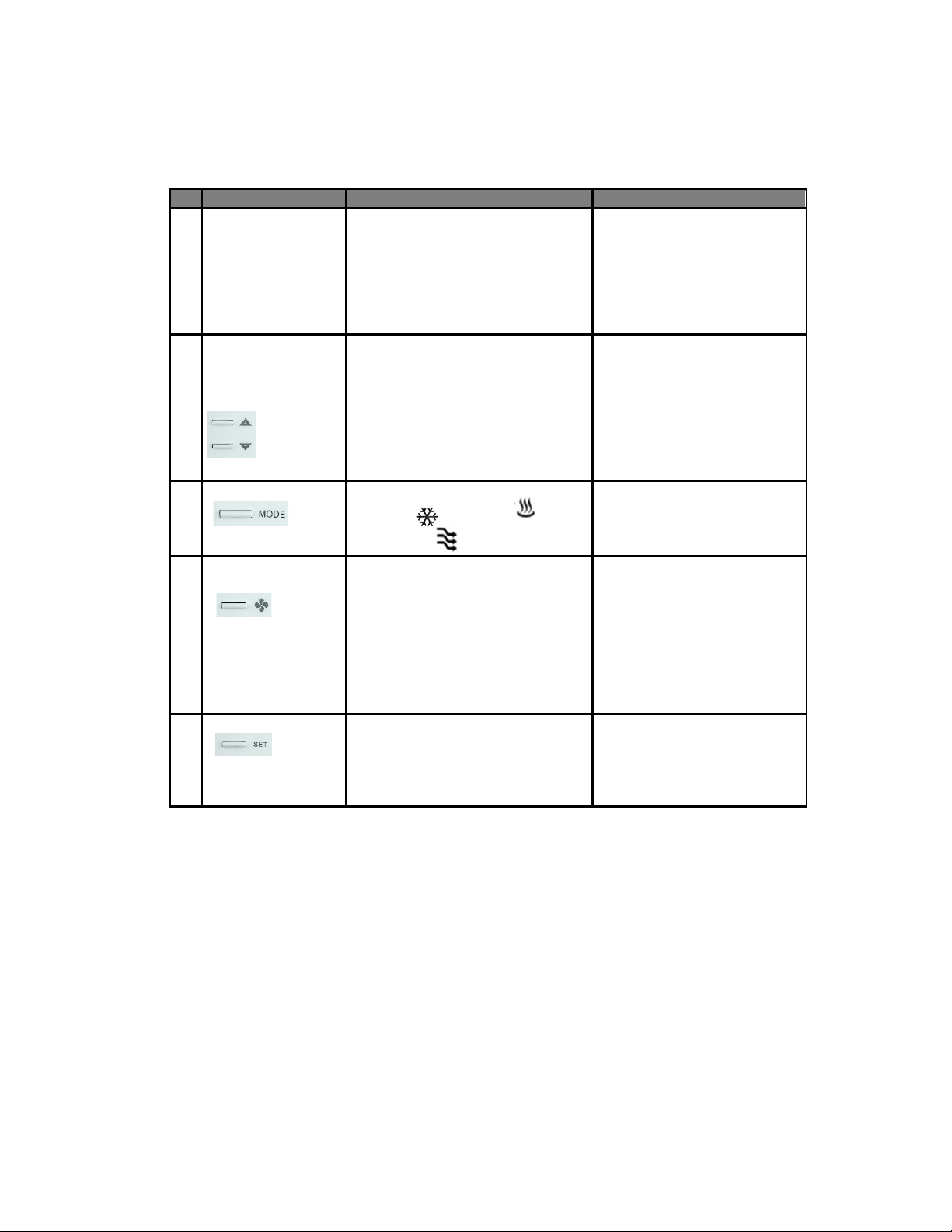
User Mode Thermostat Operation
# Item
Description
Remarks
1
Normal Display
Display current room or set-point
Use the (SP) parameter in
point temperature on display.
2
Temperature
Set the desired temperature
The [AV0] / [AV3] Cool / Heat
Occupied and [
Unoccupied
t
BACnet
objects can be used to write or
force the setpoint to a desired
value from
3
Mode Select
Select the working mode:
Ventilating (
).
After pressing the MODE
4
Fan Auto/
Change the Fan mode between
When AUTO is displayed, the
continuously until commanded
off.
5
Occupancy Setting
Press SET, Used UP and DOWN
apply.
The SET button could be
locked for applications
forbidding user occupancy
state
Setpoint Setting
using Up/Down
Arrows
Continuous
temperature
Cooling ( ), Heating ( ), or
Auto or Continuous.
the Engineering Menu or
[MSV6] Display Option for
BW2 or [MSV7] Display
Option for B2 model to
choose Current room or Set-
AV8] / [AV9]
Cool / Heat
emperature setpoints
BACnet supervisor.
button, press the UP/ DOWN
button to rotate the selections.
Dependent on Control Type.
fan is handled automatically.
When AUTO is flashing, the
fan is working under a delay
timer. When FAN icon is
spinning but AUTO is not
displayed, the fan will run
UM-15090000-AA4 Page 15
arrows to toggle between the
Occupied and Unoccupied setting.
Use MODE or SET buttons to
control.
Page 16
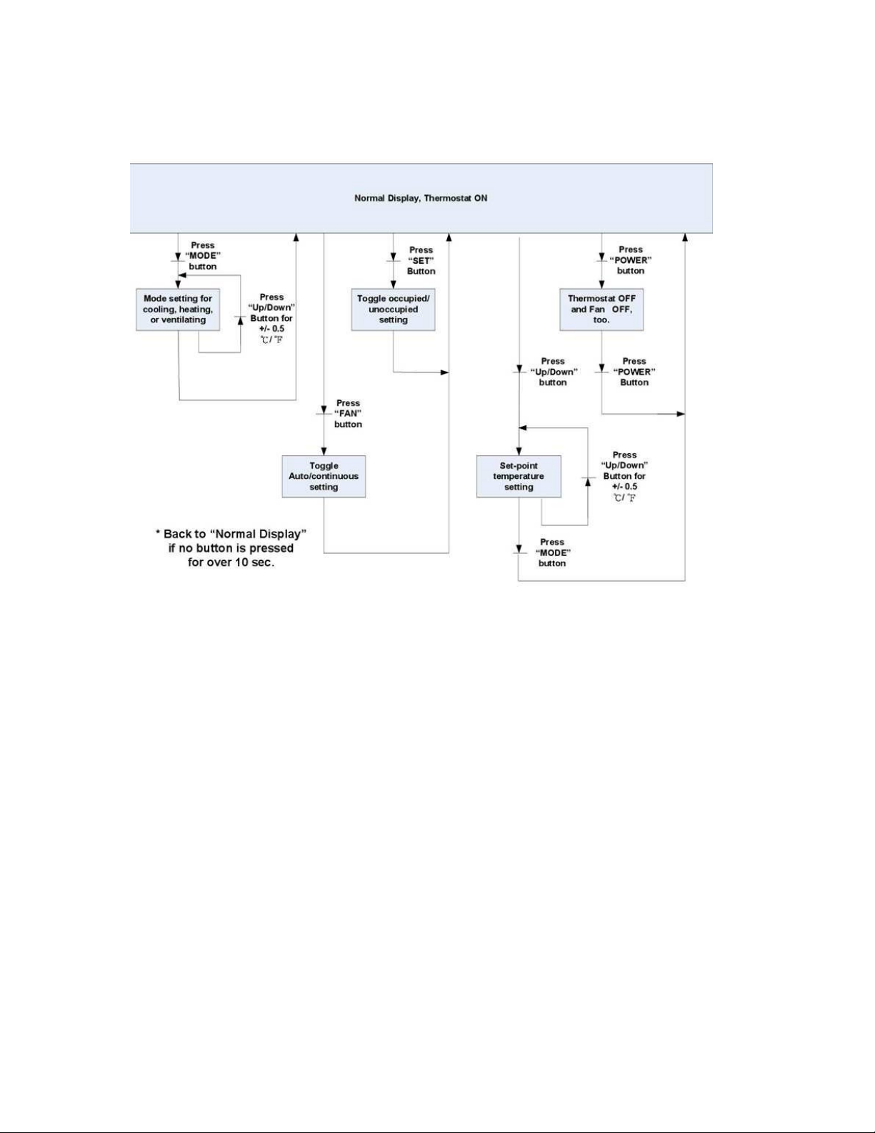
User Mode Flow Chart
4.2 Control Type
Control Type, System Mode and Algorithm Configuration
Both binary thermostat models (B2 and BW2) support two different control types, selectable in
Engineering Menu item (tyPE) or BACnet object [MSV8] Control Type for B2 model or [MSV7]
Control Type for BW2 model.
Control type unlike thermostat system mode, is not selectable by the end user, only configurable
by the installation engineer using Engineering Mode Menu (manual) or BACnet supervisor using
BACnet commands (commanded by BACnet supervisor). The engineer installing the thermostat
must decide the control type suitable for the application, set it to a static value, or program the
BACnet supervisor to change the control type automatically based on logic for the application
requirements such as change of seasons or geolocation. The default control type is set to 2stage Heating and Cooling with Auto Changeover. This is the most common control type. 2stage Heating and Cooling with Manual Changeover can be used to limit frequent automatic
change of system modes (Cool or Heat).
UM-15090000-AA4 Page 16
Page 17

System modes available to the user are dependent on control type chosen from Engineering
Menu (tyPE) or BACnet object [MSV7] Control Type for BW2 model and [MSV8] Control Type
for B2 model.
Dual Stage Heat and Cool with Auto Changeover - The default control type in the thermostat is
set to Heat and Cool with Auto Changeover. Mostly used for standalone operation. Based on an
algorithm using setpoint, current temperature, and deadband, the thermostat will switch
between Cool and Heat modes automatically. In this control type, the user will be presented with
a choice of Heat or Ventilation@Heat when the thermostat is in Heat mode (automatic), and
Cool or Ventilation@Cool when the thermostat is in Cool mode (automatic).
Dual Stage Heat and Cool with Manual Changeover – This control type is similar to Heat and
Cool with Auto Changeover but in this control type the thermostat will wait for a command from
user or BACnet supervisor to switch between Cool and Heat modes. In this control type, the
user will be presented with a choice of Heat or Ventilation@Heat when the thermostat is in Heat
mode (manual command), and Cool or Ventilation@Cool when the thermostat is in Cool mode
(manual command). The user can also choose to switch between Cool and Heat modes using
the MODE button.
BACnet controlled – The built-in thermostat algorithm can be bypassed completely, and the
thermostat can be controlled over the BACnet network with commands from supervisor device.
The logic executing in the supervisor (such as Niagara or Sedona logic) can control the
thermostat over the BACnet network. To put the thermostat in BACnet network control mode,
use the Lock [AV18] object bit 9: Control DOs by thermostat algorithm “0” (default) or BACnet
supervisor “1” (add decimal=512).
Cool Only (nullified/disabled in firmware), and Heat Only (nullified/disabled in firmware) control
types are listed in the BACnet object and Engineering Menu object but are not available for use.
They are nullified/disabled in the firmware.
Fan Output in Heat Mode
By default, the BASstat thermostat will not provide Fan output signal when in Heat Mode since
most HVAC comfort systems such as RTU systems provide their own fan control signal based
on a delay after a call for heating. This can be configured from Engineering Menu item (F-Ht) or
BACnet object [BV15] Fan Output For Heating. The default value is “0”. To enable fan control
signal output for heating coming from the BASstat, set this value to “1”.
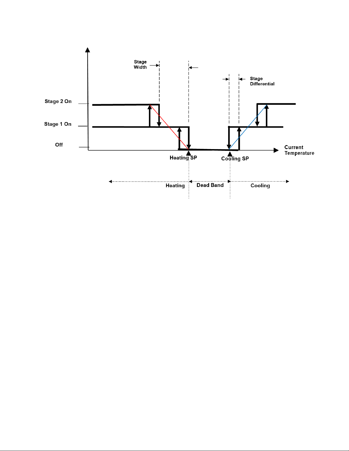
Algorithm
• A PID adaptive control algorithm is applied to minimize overshoot, in addition to
proportional band (Stage Width) and derivative (Differential) calculation.
• When the thermostat is active (either the heating or cooling stage is on), a “Working
( )” icon will be shown on the LCD.
• Stage 1 operation will show the icon ( ). Stage 2 operation will display ( ).
UM-15090000-AA4 Page 17
Page 18
System Mode
• The default control type is 2-stage cooling and heating with automatic changeover.
This makes the thermostat operate fully stand-alone. Control Type can be selected
in (tyPe) or [MSV7] or [MSV8]. Manual Changeover control type allows restriction of
mode selection to Cool only or Heat only in applications where necessary.
• Occupied Cooling [AV0] and Heating [AV3] set points and Unoccupied Cooling
[AV8] and Heating [AV9] setpoints can be set individually for cooling and heating
modes, with either manual or automatic changeover control. Minimum deadband
[AV7] can be programmed as well.
• For cooling/ heating with manual changeover control, cooling or heating can be
selected by pressing the MODE button or using a BACnet command to object [
MSV1]. In application where user control needs to be limited, the lock button
function can be used to disable MODE button.
Fan Control Output
• Fan Output for Heating - the fan output for Heat mode is disabled “0” in [BV15] by
default. The thermostat lets the RTU circuity control the fan during Heat mode. Fan
output can be enabled “1” for Heat mode if desired [BV15].
• Lowest Fan Speed is the speed the fan will default to after a control action (Heating
or Cooling). If the lowest fan speed [MSV4] is set as “Stop (1)”, the fan will be
automatically shut off after the control action (Heating or Cooling) and a 2-minute
fan-off time delay. During this delay time, the AUTO icon will be flashing, and the fan
will shut off after the 2-minute time delay expires. If lowest fan speed is set to “Low
UM-15090000-AA4 Page 18
Page 19

(2)” the fan will run continuously after a control action. This feature is useful for
thermostat models with multiple fan speeds.
• Fan Mode can be toggled between AUTO or CONTINUOS by using the FAN button
on the thermostat (user) or BACnet object [MSV0] Fan Mode (BACnet supervisor).
By default, this value is set to “Auto(1)”, the AUTO icon is displayed and the fan will
be controlled automatically. To put the fan in CONTINUOS mode set to “Low(2)”
this will cause the fan to run continuously (no AUTO icon is displayed). Fan icon
spinning when fan is active. Optionally, the FAN button can be locked to limit user
access to this feature or the BACnet supervisor can be programmed to default the
thermostat to certain state at the end of an occupancy cycle.
Short Cycle and Maximum Cycles per Hour
• There are short cycle and maximum cycles per hour protection for both cooling and
heating modes [AV23 – 26] Cooling Short Cycle Delay, Cooling Maximum Cycles
per Hour and Heating Short Cycle Delay, Heating Maximum Cycles per Hour.
• The short cycle time (in minutes) will determine the minimum on time and minimum
off time of each stage before changing its state. The default setting is 3 minutes.
• Maximum cycles per hour will count the number of cycles in an hour. When the cycle
count reaches the maximum cycles in an hour, it won’t allow additional cycles until
the next hour.
• When a stage change is pending due to a Short Cycle Delay or a Maximum Cycle
count, the Clock icon ( ) will appear on the LCD.
• To disable short cycle checking, set the short cycle to 0 minutes. NOTE: Do not use
this value unless the heating and cooling equipment is equipped with an internal
timer. Damage to equipment may occur.
Occupancy Setting
There are three ways to define thermostat occupancy state.
• Occupancy status (occupied/unoccupied) can be set by a BACnet supervisor using
writable object Occupancy Command [BV14]. Use “0” for occupied (occupied setpoints
used, sun icon displayed), and “1” for unoccupied (unoccupied setpoints used, moon
icon displayed). Occupancy Status [BI0] is a read-only BACnet object indicating
current thermostat occupancy state - “0” for occupied, and “1” for unoccupied. The
BACnet occupancy command can work in conjunction with SET button (user control)
on last-write-wins basis.
• User control of occupancy state is allowed from the SET button. Pressing the SET
button and UP/DOWN buttons will toggle the occupancy state. Press MODE or SET
buttons to confirm. The SET button can work in conjunction with BACnet occupancy
Command [BV14] on last-write-wins basis. The SET button could be locked to limit
user control (use Lock [AV18] BACnet object or (LOC) engineering menu item to lock
SET button). In this case only the BACnet supervisor can set occupancy states.
Occupancy Status [BI0] is a read-only BACnet object indicating current occupancy
state.
UM-15090000-AA4 Page 19
Page 20

• When in unoccupied state, a Moon ( ) icon will be displayed on the LCD and the
thermostat will change the set-point temperatures for Cooling and Heating to the
Unoccupied Cool Setpoint and Unoccupied Heat Setpoint [AV8 – 9]. When the state
changes back to occupied, the thermostat will return to the occupied set-point values for
Cooling Temperature Setpoint and Heating Temperature Setpoint [AV0, AV3] and a
sunlight icon( ) will be displayed to indicate occupied state on LCD.
4.3 Engineering Mode Menu
Thermostat configuration can be performed using the engineering mode menu described
below or BACnet objects using a BACnet client tool such as Contemporary Controls free
BACnet Discovery Tool (BDT)
trained engineers only, because it is related to system parameters that will affect the control
results.
Operation of Engineering Menu
. It is highly suggested that engineering mode be operated by
• At power “ON”, press and hold both the UP and DOWN buttons simultaneously for 5
seconds to enter Engineering Mode menu.
• Press the UP (ascending order of objects in table) or DOWN (descending order of
objects in table) buttons to rotate through the menu items. The last item loops back
to first item at the end of items in menu. Press the MODE button to enter a submenu
item.
• Press the UP or DOWN button to change the setting in the submenu item or hold to
speed up setting value change. Press the MODE button to confirm the setting and
return to menu item selection. If no button is pressed for 10 seconds, the display will
return to the menu item selection. After another 10 seconds, the display will return
back to User mode. Settings are not changed unless confirmed using the MODE
button.
• To leave Engineering Mode, rotate till (End) menu item appears and press the MODE
button. Alternately, pressing no buttons for 10 seconds will return the thermostat back
to User mode.
UM-15090000-AA4 Page 20
Page 21
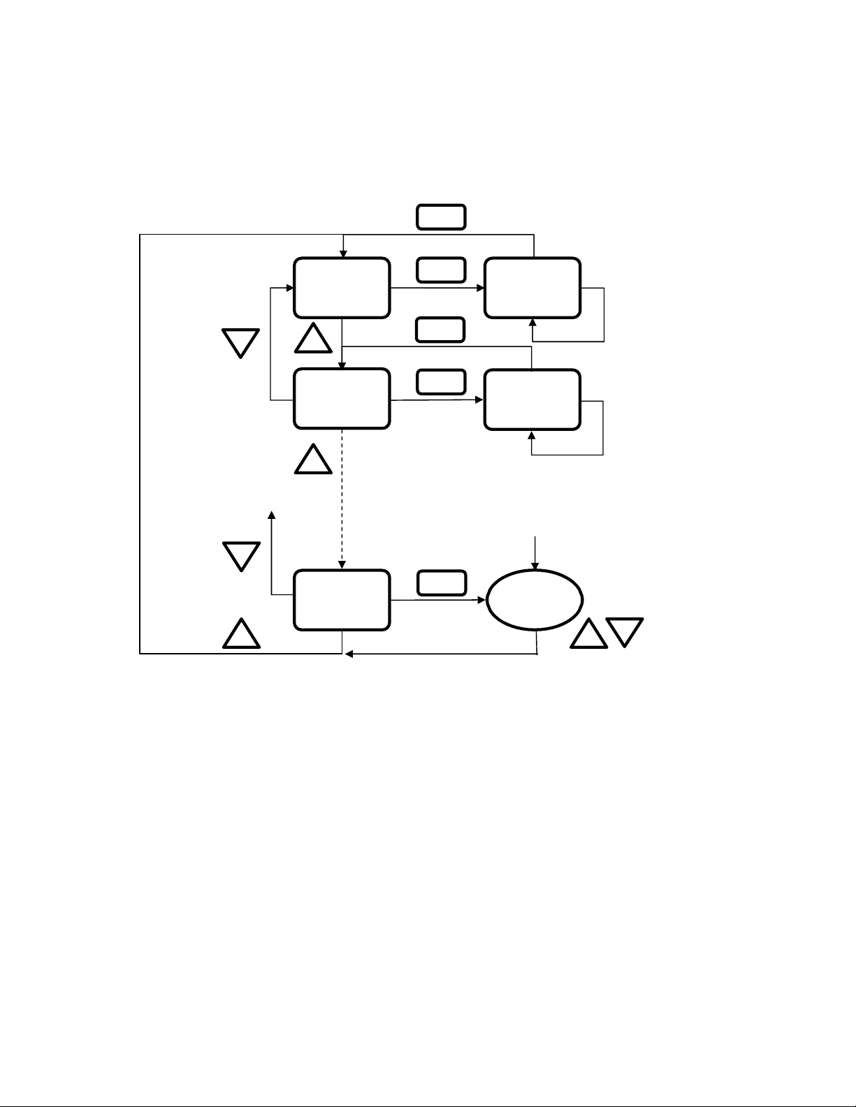
Engineering Menu Flow Chart
Press Up/down
for over 5s
MODE
MODE
E01
E01 Setting
_
+
MODE
MODE
E02
E02 Setting
+
Previous
No button pressed
for 10s under menu
item selection
_
MODE
End
User Mode
+
+
_
UM-15090000-AA4 Page 21
Page 22

Engineering Menu Items Table – BW2 Model (BACnet/IP Wi-Fi)
Unoccupied(ESI) cooling set point
Unoccupied(ESI) heating set point
Integral Time and Output Cycle Time
(seconds)
Low limit for temperature set point
High limit for temperature set point
Bit Definition:
Bit Value
parameters
Item
E1
E2
E3
E4
E5
E6
E7
E8
E9
E10 Pb Proportional band or stage width 1.5 0~10.0 3.0 0~18.0 0.1 (°C/°F)
E11 diFF Stage differential 0.5 0.1~1.0 1.0 0.1~1.8 0.1 (°C/°F)
E12 LOC
Mnemonic
db Deadband 2.0 0~10 4.0 0~18 0.5 (°C/°F)
ESIC
ESIH
I-t
OPL1 Not used
SPA1 Not used
SP-L
SP-H
OFSt Current temperature offset 0.0 -10.0~10.0 0.0 -18.0~18.0 0.1 (°C/°F)
0: MODE button (dec=1)
1: Down buttons (dec=2)
2: Up button (dec=4)
3: FAN SPEED button (dec=8)
4: Power On/Off button (dec=16)
5: SET (or ℃/℉) button (dec=32)
6: ESI contact detection (dec=64)
7: Door/Window contact
detection (dec=128)
8: Modification for communication
parameters (dec=256)
i.e. baud rate, MAC addr, device inst.
9: Control DOs by thermostat algorithm
(0) or BACnet sup. (1) (dec=512)
10~15: reserved/unused
Description
°C Scale °F Scale
Default Range Default Range
28 25~35 82.5 77~95 1.0 (°C/°F)
15 10.0~22.0 59 50.0~72.0 1.0 (°C/°F)
60 0~500 60 0-500 10 (Sec.)
10 0~50 50 32~122 1.0 (°C/°F)
30 0~50 95 32~122 1.0 (°C/°F)
64
0-1023
64
0-1023
Step
1
Examples (add dec values to lock multiples)
Unlock/enable all (0)
Lock MODE Button (1)
Lock Down Button (2)
Lock MODE & Down Buttons (3 = 1+2)
Lock Power On/Off button (4)
Lock MODE & Power & Down (7 = 1+2+4)
Lock SET button (32)
Lock MODE & Down & Power & SET (39 =
1+2+4+32)
ESI contact disable (64)
Lock the modification for communication
DOs control commanded by BACnet (512)
UM-15090000-AA4 Page 22
0: Unlock / enable
1: Lock / disable
(256)
Page 23

0: built-in
ense
BACnet
Display present temperature value of or
0
0
applicable to all models)
0: N.O.
E
Lowest Fan speed in Auto fan mode
0: stop
0~999
0~999
(if ID-H
<=4193)
(if ID-H
<=4193)
E22
devL
Device instance no. - Low bytes
1
0~302
(if ID-H
1
0~302
(if ID-H
1
= 4194)
= 4194)
UDP Port Number
47808
0~65535
(0~FFFF)
47808
0~65535
(0~FFFF)
-
30.0
1: Enable
Item
E13
E14 rE-C Not used
E15 rE-H Not used
E16
E17
E18 door
19
E20 Pct Output Percentage (not used)
E21 devH Device instance no. - Hi bytes 100
Mnemonic
ESI
rS
-SP-
LFAn
Description
ESI (DI1) digital sensor contact definition
Present Temperature is getting from built-in
temperature Sensor, remote temperature
sensor, or assigned through communication
current set-point for LCD
Door or Windows contact definition (not
Default Range Default Range
0
0
0
0
0
°C Scale °F Scale
0~1
0~2
0~1
0~1 0 0~1
0~1
0~100
0 0~100 1%
0~4194 100 0~4194
0
0
0
0~1
0~2
0~1
0~1
Step
0: N.O.
1: N.C.
1: remote s
2: assigned
through
0: display PV
1: display SP
1: N.C.
1: low
1
E23 UdP
E24 rHSt Relative Humidity Offset (not used)
E25 F-Ht Fan Output for Heating
E26 dLyC Cooling Short Cycle Delay
E27
E28 dLyH
E29
cycC
cycH
Cooling Maximum Cycles per
Hour
Heating Short Cycle
Heating Maximum Cycles per
Hour
(BAC0)
0
0
3
1~3
4
3
0~3
4
30.0~
0/1
2~6
2~255
(BAC0)
0
0
0/1
3
1~3
4
3
0~3
4
-30.0~30.0
2~6
2~255
1
0.1%RH
0: Disable
1 (minutes)
1 (cycles/hour)
1 (minutes)
1 (cycles/hour)
UM-15090000-AA4 Page 23
Page 24

Item
0: C
1: C&H Manual
2:
3: Heating
disabled
E31
OPL2
Minimum Output for AO2 (not used)
E32
SPA2
Span Offset for AO2 (not used)
E33
CO2L
CO2 Input Low Value (not used)
E34
CO2H
CO2 Input High Value (not used)
E35
C2PB
CO2 Control Output Proportional
Band
E36
C2SP
CO2 Setpoint (not used)
E37
C2Lo
CO2 Control Minimum Output (not used)
E38
AFtH
After Hour Extension Time (not used)
E39
VALL
Input Low Value of Valve Feedback
(not used)
E40
VALH
Input High Value of Valve Feedback
(not used)
E41
AI-L
Analog Input Low Value (not used)
E42
AI-H
Analog Input High Value (not used)
E43
AItp
Analog Input Type (not used)
E44
rhLO
Humidity Input Low Value (not used)
E45
rhHI
Humidity Input High Value (not used)
E46
nFAn
Minimum Fan Output (not used)
E47
hFAn
Maximum Fan Output (not used)
E48
FAnL
Low Fan Speed Setting (not used)
E49
FAn2
Med. Fan Speed Setting (not used)
E50
FAnH
Hi Fan Speed Setting (not used)
E51
Run
Modulating Fan Speed Run Type
(not used)
E52
OFFt
Minimum Off Time
180
0~600
180
0~600
5 (seconds)
E53
On-t
Minimum On Time
0
0~600
0
0~600
E54
Str
Floating Motor Full Stroke Time (not used)
E55
Phy1
MAC address 1st & 2nd bytes
hhhh
hhhh
h: 0~F in hex
E56
Phy2
MAC address 3rd & 4th bytes
hhhh
hhhh
E30
Mnemonic
tyPE
Description
Control Type
(not used)
°C Scale °F Scale
Default Range Default Range
2
1~2
2
1~2
Step
ooling Only
C&H Auto
Only
NOTE: Cool
only and Heat
only types
UM-15090000-AA4 Page 24
5 (seconds)
h: 0~F in hex
Page 25

Item
E57
Phy3
MAC address 5th & 6th bytes
hhhh
hhhh
E58
IP-1
1st byte of IPv4 address
192
0~255
192
0~255
E59
IP-2
2nd byte of IPv4 address
168
0~255
168
0~255
E60
IP-3
3rd byte of IPv4 address
0
0~255
0
0~255
E61
IP-4
4th byte of IPv4 address
1
0~255
1
0~255
E62
tESt
Self-Diagnostic – toggle all LCD features and
all
Use
Caution!
Press MODE to
engage test
E63
boot
Reset Wi-Fi parameters to factory defaults
Press MODE to
reset
E64
rSt
Reset all parameters including communication
and control algorithm to the factory defaults
Use
Caution!
Press MODE to
reset
E65
Exit Engineer Mode Menu
Press MODE to
exit engineering
menu
Mnemonic
Description
°C Scale °F Scale
Default Range Default Range
Step
h: 0~F in hex
1
1
1
1
End
relays. Use only to test
Lock Function Setup and Examples
The 16-bit binary encoded decimal register accessed through Lock [AV17] BACnet object and
LOC engineering menu item is used to enable/disable features in the thermostat. The first 10
bits are used (bit 0 ~ bit 9), bits 10~15 are reserved/unused. Bits are represented by their
decimal values and are added or subtracted to toggle from “0” to “1”. Add a bit’s decimal value
to toggle to “1” or subtract a bit’s decimal value to toggle to “0”. See table below.
UM-15090000-AA4 Page 25
Page 26

Add decimal values to lock multiples. Bold decimal number is
Bit Definition: Decimal Value to Write:
0: MODE button (dec=1)
1: DOWN button (dec=2)
2: UP button (dec=4)
3: FAN SPEED button (dec=8)
4: POWER On/Off button (dec=16)
5: SET (or ℃/℉) button (dec=32)
6: ESI contact detection (dec=64)
7: Door/Window contact
detection (unused) (unused)
8: Modification for communication
parameters (dec=256)
i.e. baud rate, MAC addr, device inst.
9: Control DOs by thermostat algorithm
(0) or BACnet sup. (1) (dec=512)
10~15: reserved/unused (unused)
Bit Value:
0: Unlock / enable
1: Lock / disable
the example value to write to Lock object. Examples:
Unlock/enable all (0) – this will also enable ESI DI1 (add 64 to all values
below to maintain default occupancy selection over BACnet).
Lock MODE button (1)
Lock DOWN button (2)
Lock MODE & DOWN (3 = 1+2)
Lock UP button (4)
Lock MODE & DOWN & UP (7 = 1+2+4)
Lock FAN SPEED button (8)
Lock MODE & DOWN & UP & FAN (15 = 1+2+4+8)
Lock POWER button (16)
Lock MODE & DOWN & UP & FAN & POWER (31 = 1+2+4+8+16)
Lock SET button (32)
Lock MODE & DOWN & UP & FAN & POWER & SET (63 =
1+2+4+8+16+32)
ESI contact disable (64 – default). When the default value of 64 is
maintained, occupancy is set over BACnet and SET user button.
Lock MODE & DOWN & UP & FAN & POWER & SET & disable ESI DI1
(127 = 1+2+4+8+16+32+64)
Door/Window contact detection (unused)
Lock the modification for communication parameters such as baud rate
and mac address (256)
Lock MODE & DOWN & UP & FAN & POWER & SET & disable ESI DI1
& modification for communication parameters (383 =
1+2+4+8+16+32+64+256)
DOs control commanded by BACnet (512)
UM-15090000-AA4 Page 26
Page 27

Engineering Menu Items Table – B2 Model (BACnet MS/TP)
Unoccupied(ESI) cooling set point
Unoccupied(ESI) heating set point
Integral Time and Output Cycle Time
(seconds)
Low limit for temperature set point
High limit for temperature set point
Bit Definition:
Bit Value
parameters
Item
E1
E2
E3
E4
E5
E6
E7
E8
E9
E10 Pb Proportional band or stage width 1.5 0~10.0 3.0 0~18.0 0.1 (°C/°F)
E11 diFF Stage differential 0.5 0.1~1.0 1.0 0.1~1.8 0.1 (°C/°F)
E12 LOC
Mnemonic
db Deadband 2.0 0~10 4.0 0~18 0.5 (°C/°F)
ESIC
ESIH
I-t
OPL1 Not used
SPA1 Not used
SP-L
SP-H
OFSt Current temperature offset 0.0 -10.0~10.0 0.0 -18.0~18.0 0.1 (°C/°F)
0: MODE button (dec=1)
1: Down buttons (dec=2)
2: Up button (dec=4)
3: FAN SPEED button (dec=8)
4: Power On/Off button (dec=16)
5: SET (or ℃/℉) button (dec=32)
6: ESI contact detection (dec=64)
7: Door/Window contact
detection (dec=128)
8: Modification for communication
parameters (dec=256)
i.e. baud rate, MAC addr, device inst.
9: Control DOs by thermostat algorithm
(0) or BACnet sup. (1) (dec=512)
10~15: reserved/unused
Description
°C Scale °F Scale
Default Range Default Range
28 25~35 82.5 77~95 1.0 (°C/°F)
15 10.0~22.0 59 50.0~72.0 1.0 (°C/°F)
60 0~500 60 0-500 10 (Sec.)
10 0~50 50 32~122 1.0 (°C/°F)
30 0~50 95 32~122 1.0 (°C/°F)
64
0-1023
64
0-1023
Step
1
Examples (add dec values to lock multiples)
Unlock/enable all (0)
Lock MODE Button (1)
Lock Down Button (2)
Lock MODE & Down Buttons (3 = 1+2)
Lock Power On/Off button (4)
Lock MODE & Power & Down (7 = 1+2+4)
Lock SET button (32)
Lock MODE & Down & Power & SET (39 =
1+2+4+32)
ESI contact disable (64)
Lock the modification for communication
DOs control commanded by BACnet (512)
UM-15090000-AA4 Page 27
0: Unlock / enable
1: Lock / disable
(256)
Page 28

0: built-in
sense
BACnet
Display present temperature value of or
0
0
applicable to all models)
0: N.O.
E
Lowest Fan speed in Auto fan mode
0: stop
38.4
9.6kbps
38.4
9.6kbps
9.6kbps
0~999
0~999
(if ID-H <=
(if ID-H
E24
devL
Device instance no. - Low bytes
1
4193) 1
<=4193)
1
0~302
0~302
( if ID-H
( if ID-H
= 4194)
= 4194)
Max_Master -- The highest allowed MAC
address for BACnet MS/TP master nodes
30.0
1: Enable
Item
E13
Mnemonic
ESI
Description
ESI (DI1) digital sensor contact definition
E14 rE-C Not used
E15 rE-H Not used
Present Temperature is getting from built-in
E16
E17
rS
-SP-
E18 door
19
LFAn
temperature Sensor, remote temperature
sensor, or assigned through communication
current set-point for LCD
Door or Windows contact definition (not
E20 Pct Output Percentage (not used)
E21
Baud BACnet MS/TP Baud rate
°C Scale °F Scale
Step
Default Range Default Range
0
0~1
0
0~1
0: N.O.
1: N.C.
1: remote
0
0~2
0
0~2
2: assigned
through
0~1
0
0
0
0~1 0 0~1
0~3
0~100
19.2kbps
0 0~100 1%
0
38.4kbps
57.6kbps
76.8kbps
0~1
0~1
19.2kbps
38.4kbps
57.6kbps
76.8kbps
0: display PV
1: display SP
1: N.C.
1: low
19.2kbps
38.4kbps
57.6kbps
76.8kbps
E22
Addr
BACnet MS/TP MAC address
E23 devH Device instance no. - Hi bytes 100
E25 AdrH
E26 rHSt Relative Humidity Offset (not used)
E27 F-Ht Fan Output for Heating
E28 dLyC Cooling Short Cycle Delay
E29
cycC
Cooling Maximum Cycles per
Hour
UM-15090000-AA4 Page 28
1
0~127
127
1~127
0
0
3
1~3
4
1
0~127
0~4194 100 0~4194
-30.0~
0/1
2~6
127
0
0
3
4
1~127
-30.0~30.0
0/1
1~3
2~6
1
1
1
0.1%RH
0: Disable
1 (minutes)
1 (cycles/hour)
Page 29

Item
0: Cooling Only
1: C&H Manual
2: C&H Auto
3: Heating Only
disabled
E33
OPL2
Minimum Output for AO2 (not used)
E34
SPA2
Span Offset for AO2 (not used)
E35
CO2L
CO2 Input Low Value (not used)
E36
CO2H
CO2 Input High Value (not used)
E37
C2PB
CO2 Control Output Proportional
Band
E38
C2SP
CO2 Setpoint (not used)
E39
C2Lo
CO2 Control Minimum Output (not used)
E40
AFtH
After Hour Extension Time (not used)
E41
VALL
Input Low Value of Valve Feedback
(not used)
E42
VALH
Input High Value of Valve Feedback
(not used)
E43
AI-L
Analog Input Low Value (not used)
E44
AI-H
Analog Input High Value (not used)
E45
AItp
Analog Input Type (not used)
E46
rHLO
Humidity Input Low Value (not used)
E47
rHHI
Humidity Input High Value (not used)
E48
nFAn
Minimum Fan Output (not used)
E49
hFAn
Maximum Fan Output (not used)
E50
FAnL
Low Fan Speed Setting (not used)
E51
FAn2
Med. Fan Speed Setting (not used)
E52
FAnH
Hi Fan Speed Setting (not used)
E53
Run
Modulating Fan Speed Run Type
(not used)
E54
OFFt
Minimum Off Time
180
0~600
180
0~600
5 (seconds)
E55
On-t
Minimum On Time
0
0~600
0
0~600
E56
Str
Floating Motor Full Stroke Time (not used)
E57
tESt
Self-Diagnostic – toggle all LCD features and
all relays. Use only to test
Use
Caution!
Press MODE to
Mnemonic
Description
°C Scale °F Scale
Default Range Default Range
Step
E30 dLyH
E31
E32
cycH
tyPE
Heating Short Cycle
Heating Maximum Cycles per
Hour
Control Type
(not used)
3
0~3
4
2
2~255
1~2
3
0~3
4
2~255
2
1~2
1 (minutes)
1 (cycles/hour)
NOTE: Cool
only and Heat
only types
UM-15090000-AA4 Page 29
5 (seconds)
Page 30

Item
engage test
E58
rSt
Reset all parameters including communication
and control algorithm to the factory defaults
Use
Caution!
Press MODE to
E59
Exit Engineer Mode Menu
Press MODE to
exit engineering
menu
Mnemonic
Description
°C Scale °F Scale
Default Range Default Range
Step
End
4.4 BACnet Objects and Network Configuration
Transmission types (model dependent)
BASstat B2:
• Physical layer: EIA-485
• Protocol: BACnet MS/TP
• Baud rate: 9600-76800bps (38400bps default)
• MAC address: 1 (default)
• Device Instance: 100001
load reset
BASstat BW2:
• Physical layer: Wi-Fi 802.11 b/g/n
• Protocol: BACnet/IP
• UDP Port Number: BAC0 (47808)
• MAC address: Wi-Fi chip MAC address found written on the back side of thermostat or
in Engineering Menu item (Phy3). This can assist when multiple Wi-Fi thermostats are installed.
• Device Instance: 100001
UM-15090000-AA4 Page 30
Page 31

Initial Configuration
Initial communication configuration differs depending on whether you are using the BACnet
MS/TP model (B2) or BACnet/IP over Wi-Fi model (BW2). All configuration parameters are
settable through use of the buttons on thermostat by entering the Engineer Menu, or once
installed on the BACnet network, configuration can also be altered using BACnet commands.
Network command-based configuration can also be accomplished on the bench using a BACnet
router (B2 MS/TP model) or Wi-Fi enabled laptop/computer/tablet/smart phone (BW2 Wi-Fi
model) and our free BACnet Discovery Tool.
B2 model - MS/TP Communication Configuration
Overview
The BASstat MS/TP thermostat is preconfigured with a MAC address of 1 and default baud rate
of 38400bps. To alter this configuration, enter the Engineering Menu by holding down the UP
and DOWN buttons simultaneously for 5 seconds. Use the UP and DOWN buttons to navigate
through the menu and change menu item values. Use the MODE button to enter a menu item
and accept/confirm a selected value. To exit the Engineering Menu, navigate to menu item
(End) and press MODE to confirm, or the menu will exit automatically when not used after 5
seconds. BACnet MS/TP model configuration requires setting the baud rate or using the default
baud rate of 38.4kbps. A unique MS/TP MAC address is required to distinguish it from other
MS/TP devices on the bus (default MAC address = 1). When more than one BASstat is installed
at the same time, their MAC addresses must be configured prior to communicating on the
BACnet MS/TP bus or communication will fail due to duplicate MAC addresses. A unique
Device Instance Number throughout the entire BACnet internetwork is also required to
distinguish the device from all other BACnet devices.
End-of-Line Termination
The BASstat does not provide End-of-Line termination. If the BASstat is the first or last device
on the MS/TP bus, a termination resistor (120Ω) must be applied across pins 16 and 17 of the
input terminal.
Addressing
The MAC address can be set from Engineering Menu item (Addr) with values of 1 - 127.
The Baud rate can be set from Engineering Menu item (bAud) 9.6kbps – 76.8kbps.
A unique Device Instance Number throughout the entire BACnet internetwork is also required to
distinguish the device from all other BACnet devices. Device instance can be modified in
Engineering Menu items (dEVH) – high bytes and (dEVL) – low bytes.
Device Instance = (dEVH)*1000+(dEVL). Device Instance example: if (dEVH) is set to 4194 and
(dEVL) is set to 7, the Device Instance Number = 4194007. Device Instance Number can also
be changed by writing to BACnet object [AV21] Device Instance once the thermostat is online.
Max masters setting can be set from Engineering Menu item (AdrH), default value is 127.
UM-15090000-AA4 Page 31
Page 32

Reset Settings
Thanks to its EEPROM, the BASstat will store configuration in the event of power loss. All
settings can be reset back to default from Engineering Menu item (rSt). Use caution because
once this item is selected (MODE button to select), all settings will be reset to their default
values.
BW2 model - Wi-Fi Communication Configuration
Overview
The BASstat Wi-Fi thermostat is preconfigured with a BACnet Device Instance of 100001 and a
UDP Port Number of 47808 (decimal) equivalent to BAC0 (hexadecimal). To alter this
configuration, enter the Engineering Menu by holding down the UP and DOWN buttons
simultaneously for 5 seconds. Use the UP and DOWN buttons to navigate through the menu
and change menu item values. Use the MODE button to enter a menu item and accept/confirm
a selected value. To exit the Engineering Menu, navigate to menu item (End) and press MODE,
or the menu will exit automatically when not used after 5 seconds.
Addressing
A unique Device Instance Number throughout the entire BACnet internetwork is required to
distinguish the device from all other BACnet devices. When more than one BASstat is installed
at the same time, their Device Instance Number must be configured prior to connecting to the
BACnet/IP network or BACnet communication will fail due to duplicate device instances.
Device instance can be modified in Engineering Menu items (dEVH) – high bytes and (dEVL) –
low bytes. Device Instance = (dEVH)*1000+(dEVL). Device Instance example: if (dEVH) is set
to 4194 and (dEVL) is set to 7, Device Instance Number = 4194007. Device Instance Number
can also be changed by writing to BACnet object [AV21] Device Instance once the thermostat is
online. The BACnet UDP Port Number can be configured in Engineering Menu item (UdP).
BACnet/IP Wi-Fi (BW2) model will initially boot up as a Wi-Fi Access Point to allow for IP
configuration. This requires connecting to the thermostat as an access point for initial
configuration using a Wi-Fi enabled laptop/computer/tablet/smart phone. Look for the BASstat221C-BW2 with its unique SSID of “WiFi-122B-xxxx” and no access point passphrase by default
(simply click to connect to Access Point). The digits “xxxx” in “122B-xxxx” are the last 4 digits of
the thermostat’s Wi-Fi chip MAC address found written on the back side of the Wi-Fi module.
This ensures a unique SSID for discovery and configuration and it can assist in identification of
thermostats when multiple Wi-Fi stats are installed on the same site (unique identifier outlined in
blue in the image below). This unique identifier can also be viewed in Engineering Menu item
(Phy3).
UM-15090000-AA4 Page 32
Page 33
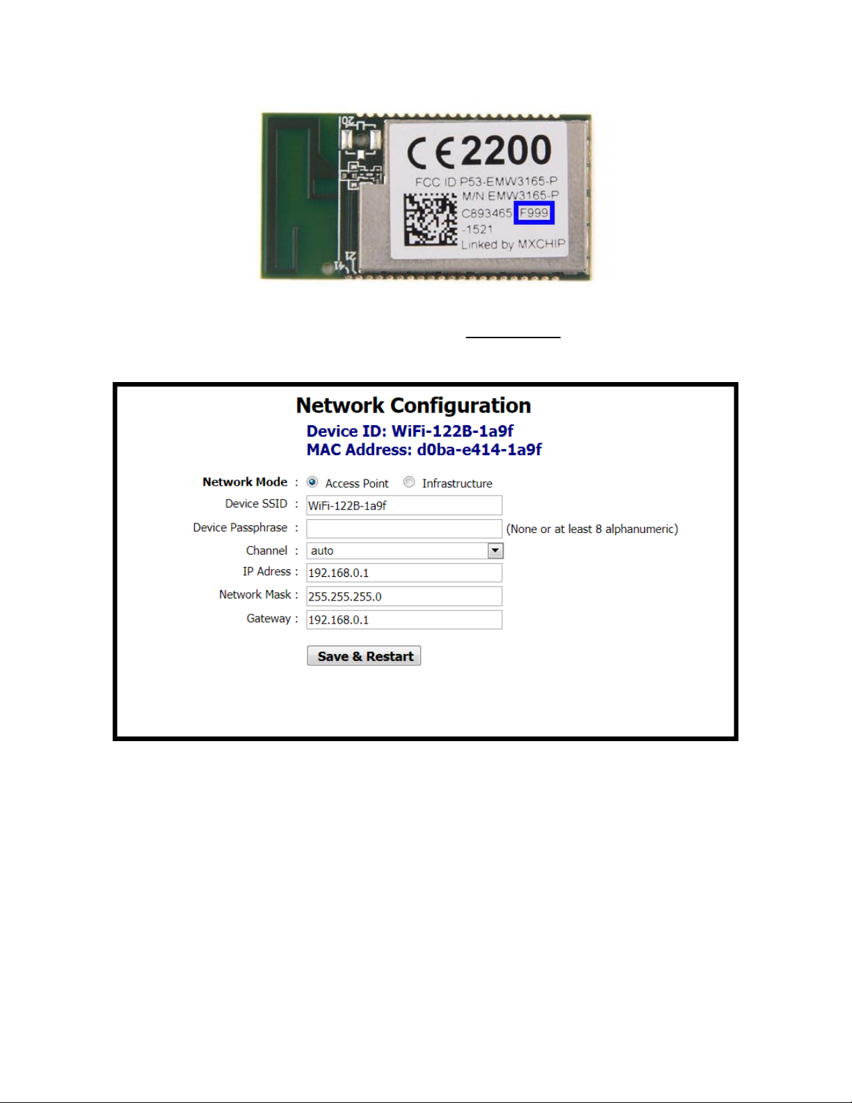
Once connected to the thermostat as an access point, open its web page by typing its default
address of 192.168.0.1 with admin for username and no password. Web page pictured below
will be presented for IP Network Configuration. The default IP configuration is shown below.
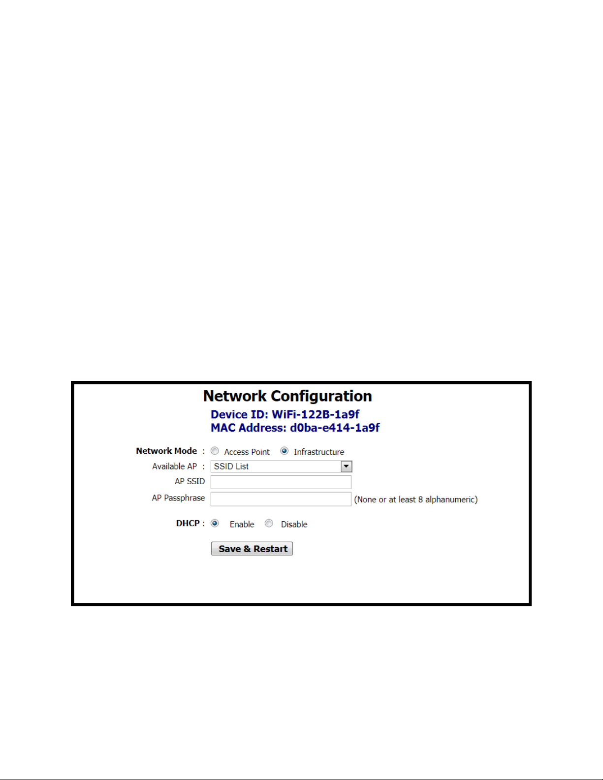
After initial connection using laptop or tablet or smart phone, the Wi-Fi mode in the thermostat
can be changed to Infrastructure mode. The local Wi-Fi router/access point can be selected
from the Available AP drop-down list, or an AP SSID can be entered manually. Enter the AP
Passphrase to authenticate and connect to the AP.
ATTENTION: When setting up the Wi-Fi router (Access Point) the thermostats will be connected
to, make sure you set up a strong access point passphrase (password)! This is required for WiFi client devices to connect to the Wi-Fi router and it is essential to cyber security. Creating a
good Wi-Fi password is the first step in creating a secure environment that is inaccessible to
unauthorised parties. Use the following tips when creating a Wi-Fi access point passphrase:
UM-15090000-AA4 Page 33
Page 34
• Passphrase should be a minimum of eight characters (maximum 15 characters), the
more random the better. Use a mix of letters (uppercase and lowercase), numbers, and
symbols.
• Misspelling commonly used words and replacing some of the letters with numbers or
symbols is a good practice and makes passwords difficult to guess.
• Avoid using instances like "abc1234", "123456789", "password", "qwerty", "111111",
"admin", "iloveyou" and "aaaaaa".
• Do not reuse or repeat passwords across router installations or job sites.
• Change WiFi password regularly (not required but very secure). Provides guidelines for
building maintenance personnel.
• Disable broadcast of SSID. This is a very simple setting which stops the broadcast of the
access point SSID, and only authorized parties who know the SSID can connect to it.
This is configured in the Wi-Fi router.
• Store passwords in a safe place, limit access to authorized parties only, and provide
instructions for password reset and reconfiguring a strong password in cases of
reconfiguring the network in the future.
Choose an option for DHCP addressing using the radio buttons.
UM-15090000-AA4 Page 34
Page 35
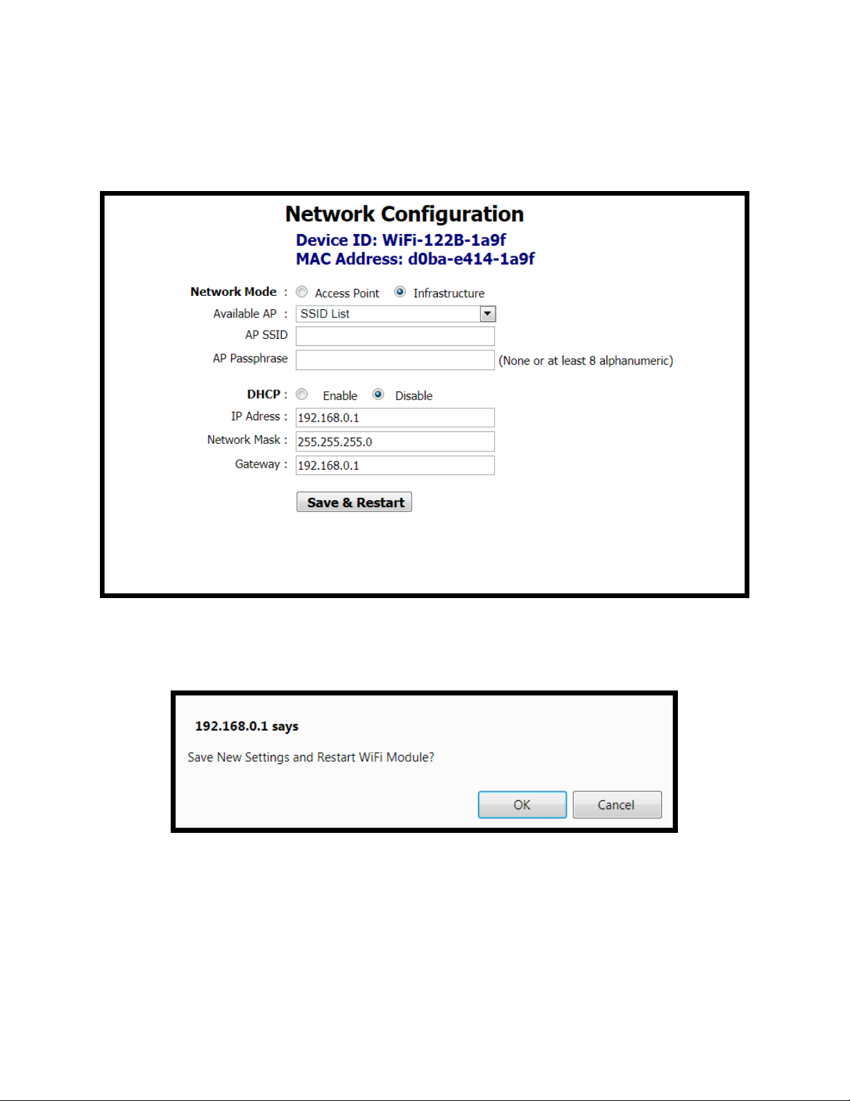
The thermostat supports DHCP addressing and will acquire an IP address from the
router/access point automatically if you chose Enable next to DHCP. If you chose Disable, you
must assign an IP Address, Network Mask, and Gateway Address within the Wi-Fi router IP
subnet manually.
A reboot of the thermostat is required for new IP configuration to take effect. Click the Save &
Restart button to reboot the thermostat, and you will be prompted to confirm the restart. Click
OK to Save New Settings and Restart or click Cancel to revisit IP configuration.
When OK is clicked a confirmation is displayed to indicate configuration is stored in the
thermostat’s EEPROM. After reboot, the new thermostat credentials will be admin for user name
and the newly configured Access Point’s password for password.
UM-15090000-AA4 Page 35
Page 36

Click OK on the confirmation message and wait 20 seconds for the reboot process to complete.
While rebooting, the thermostat will display “DP” icon in the lower right corner to indicate it is in
the process of searching and connecting to the AP. Once the “DP” stops flashing, the
thermostat has successfully connected to Wi-Fi access point. After reboot of the thermostat, the
new Infrastructure mode with new IP settings will be used. The thermostat will now be
connected to the local Wi-Fi network AP selected in configuration screen and will not show up
as an access point itself any more. If you are unsure of the thermostat’s IP address, it could be
viewed through the Engineering Menu in items (IP-1) for the first octet, (IP-2) for the second
octet, (IP-3) for the third, and (IP-4) for the fourth octet of the IP address, or if you have access
to the Wi-Fi access point, its “statistics” or “connected devices” web page will show the BASstat
BW2’s IP address as well as MAC address (the same address in Engineering Menu items Phy1,
Phy2, and Phy3 and the printed MAC on the back of the thermostat Wi-Fi module (outlined in
blue above).
Reset Settings
Thanks to its EEPROM, the BASstat will store configuration in the event of power loss. If
configuration fails or the thermostat needs to be configured to use a different Wi-Fi access point,
the thermostat must be reset and reconfigured. There are 2 reset settings options for the Wi-Fi
thermostat:
- Boot will restore Wi-Fi communication parameters to default, but it will maintain control
algorithm settings. Select (boot) engineering menu item and press MODE to confirm.
- Reset will restore all values to default and can be selected from engineering menu (rSt).
UM-15090000-AA4 Page 36
Page 37

BACnet Object Table - B2 Model (BACnet MS/TP)
Object name
Type & Instance
Object Property
(Readable/Writable)
Range
BACnet Thermostat
Model Name (R)
Type &
Instance
Readable/
Writable
℃/°F
(32.0~122.0°F)
Built-in
Remote
Current Humidity
AI 4 R
Current Humidity
0~1000: 0.0~100.0%RH
℃/°F
Current CO2
Reading
Control Valve
Feedback
Modulating/
Floating Output 1
Modulating/ Floating Output
1
0~100: 0~100 %
Modulating/
Floating Output 2
Modulating/ Floating Output
2
0~100: 0~100 %
Modulating Fan
Output
0~100: 0~100 %
CO2 Control Output
Percentage
CO2 Control Output
Percentage
Voltage Input Value
Voltage Input Value
0~150 (0.0~15.0 VDC)
Analog Input 1
Value
Analog Input 1 Percentage
Value
Device 100001
Application Software Version (R)
Object Identifier (R)
Object Name (R/W) 32 characters (max.)
Object name
Current
Temperature
Temp SP Status
Temperature
Sensor
Temperature
Sensor
Current Dew Point
AI 0
AI 1
AI 2
AI 3
AI 5
Max_Master (R/W)
Description Range and Definition
R
R
R
R
R
Current Temperature
Active Temperature SetPoint
Built-in Temperature
Sensor Reading
Remote Temperature
Sensor Reading
Current Dew Point
1~127
-999~9999: -99.9~999.9
°C :0~500 (0.0~50.0℃)
°F : 320~1220
-999~9999:-99.9~999.9
℃/°F
-999~9999:-99.9~999.9
℃/°F
-999~9999: -99.9~999.9
UM-15090000-AA4 Page 37
AI 6
AI 7
AI 8
AI 9
AI 10
AI 11
AI 12
AI 13
R
R
R
R
R
R
R
R
Current CO
Control Valve Feedback
Modulating Fan Output
Reading
2
0~3000: 0~3000 ppm
0~1000 (0.0%~100.0%)
0~100: 0~100 %
0~1000 (0.0%~100.0%)
Page 38

Analog Input 2
Value
AI 14
Analog Input 2 Percentage
Value
Analog Input 3
Value
Analog Input 3 Percentage
Value
(32.0~122.0°F)
Temperature
AV 1
Assigned Current
Timer Off (Only for Models
0: Disable
AV 3
Heating Temperature Set
For Writing.
AV 5
Running Time of Valve
Sec-Running
AV 6
Running Time of Valve
AV 7
Deadband
Unoccupied Cooling Setpoint
°F)
AV 9
R/W
Integral-Cycle
Time
Integral Time and Output
Cycle Time
Analog Minimum
AV 11
R/W
Minimum Output Voltage in
Span Offset
Span Offset for AO1
(32.0~122.0°F)
(32.0~122.0°F)
R
0~1000 (0.0%~100.0%)
Cooling Setpoint
Override
Timer Off
Heating Setpoint
Hr-Running Time
M-Running Time
Time
AI 15
AV 0
AV 2
AV 4
R
R/W
R/W
R/W
R/W
R/W
R/W
R/W
Cooling Temperature Set
Point
Temperature
with Countdown Timer
Function
Available).
Point
Running Time of Valve (Hr.)
(M.)
(Sec.)
0~1000 (0.0%~100.0%)
°C :0~500 (0.0~50.0℃)
°F: 320~1220
-999~9999
(-99.9~999.9℃/°F)
0~24: 0~24 Hours Count
Down
-999~9999: -99.9~999.9
℃/°F
0~65535 (Hr.) For
Reading But 0~30000 (Hr.)
0~59 (Minute)
0~59 (Sec.)
Deadband
Unoccupied Cool
Setpoint
Unoccupied Heat
Setpoint
Output
Low Setpoint Limit
High Setpoint Limit
AV 8
AV 10
AV 12
AV 13
AV 14
R/W
R/W
R/W
R/W
R/W
R/W
Unoccupied Heating
Setpoint
Digital Value When Reach
Low Limit for AO1
Low Limit for Set-Point
Temperature
High Limit for Set-Point
Temperature
°C: 0~100 (0.0~10.0 °C)
°F: 0~180 (00~18.0 °F)
°C: 250~300 (25.0~30.0
°C)
°F: 770~860 (77.0~86.0
°C: 100~220 (10.0~22.0
°C)
°F: 500~715(50.0~71.5°F)
0~500 (Sec.)
0~125 (LSB)
-55~0 (LSB)
°C :0~500 (0.0~50.0℃)
°F: 320~1220
°C :0~500 (0.0~50.0℃)
°F: 320~1220
UM-15090000-AA4 Page 38
Page 39

Temperature Offset
°F)
Proportional Band-
°F: 0~180 (00~18.0 °F)
AV 17
R/W
°F: 1~18 (0.1~1.8 °F)
Bit Definition:
(dec=512)
Bit Value
AV 19
R/W
Percentage of Modulating/
MAC Address
MAC address
AV 15
R/W
Offset for Current
Temperature
°C: -100~100 (- 10.0~10.0
°C)
°F: -180~180 (-18.0~18.0
Stage
Width
Stage Differential
Lock
AV 16
AV 18
R/W
RW
Proportional Band or Stage
Width
Stage Differential
LOCK
°C :0~100 (00~10.0 °C)
°C :1~10 (0.1~1.0 °C)
0: MODE button
(dec=1)
1: Down
buttons (dec=2)
2: Up button
(dec=4)
3: FAN SPEED button
(dec=8)
4: Power On/Off button
(dec=16)
5: SET (or ℃/℉) button
(dec=32)
6: ESI contact
detection (dec=64)
7: Door/Window
contact
detection (dec=128)
8: Modification for
communication
parameters (dec=256)
i.e. baud rate, MAC addr,
device inst.
9: Control DOs by
thermostat algorithm
(0) or BACnet sup. (1)
10~15: reserved/unused
Control Out
Percentage
UM-15090000-AA4 Page 39
AV 20
R/W
Floating Control Output
0: Unlock / enable
1: Lock / disable
Examples (add dec values to
lock multiples) For more details
see Lock Function Setup and
Examples section of this manual
0~100 (0%~100%)
0~127
Page 40

0~4194302
needs to unlock modification
LOCK(AV17) for details)
AV 22
R/W
%RH)
Cooling Short Cycle
AV 23
R/W
Cooling Short Cycle Delay
Cooling Maximum
AV 24
R/W
Heating Short Cycle
AV 25
R/W
Heating Short Cycle Delay
Heating
AV 26
R/W
AV 27
R/W
Minimum Output Voltage in
Span Offset for
AO2
Span Offset for AO2
CO2 Input Low
Value
CO2 Input Low Value
CO2 Input High
Value
CO2 Input High Value
CO2 Control Output
Proportional Band
CO2 Control Output
Proportional Band
CO2 Setpoint
CO2 Setpoint
CO2 Control
Minimum Output
CO2 Control Minimum
Output Percentage
After Hour Extension
Time
After Hour Extension Run
Time
Input Low Value of
Valve Feedback
Input Low Value of Control
Valve Feedback
Input High Value of
Valve Feedback
Input High Value of Control
Valve Feedback
Analog Input Low
Value
Analog Input Low Value
Analog Input High
Value
Analog Input High Value
%RH)
Humidity Input High
%RH)
Device Instance
AV 21
R/W
Device Instance
(Note: Changing this value
for communication
parameters in advance.
i.e. AV17=0~255 or
512~768. Please refer to
Humidity Offset
Cycles
per Hour
Maximum Cycles
per Hour
Minimum Output for
AO2
AV 28
AV 29
AV 30
AV 31
R/W
R/W
R/W
R/W
Humidity Offset Value
Cooling Maximum Cycles
per Hour
Heating Maximum Cycles
per Hour
Digital Value When Reach
Low Limit for AO2
-300~300 (-30.0~30.0
1~3 Minutes
2~6 Cycles
0~3 Minutes
2~8 Cycles
0~125 (LSB)
-55~0 (LSB)
0~1000 ppm
1000~3000 ppm
100~2000 ppm
Humidity Input Low
Value
Value
UM-15090000-AA4 Page 40
AV 32
AV 33
AV 34
AV 35
AV 36
AV 37
AV 38
AV 39
AV 40
R/W
R/W
R/W
R/W
R/W
R/W
R/W
R/W
R/W
Humidity Input Low Value
Humidity Input High Value
600~1000 ppm
0~20%
5~20(0.5~2.0) Hour
0~1000 (0.0~100.0 %)
0~1000 (0.0~100.0 %)
0~1000 (0.0~100.0 %)
0~1000 (0.0~100.0 %)
0~1000 (0.0~100.0
0~1000 (0.0~100.0
Page 41

Minimum Fan
Output
AV 41
R/W
Minimum Fan Output at Auto
Maximum Fan
AV 42
R/W
Maximum Fan Output at
Low Fan Speed
Low Fan Speed Setting (for
Med. Fan Speed
AV 44
R/W
Med. Fan Speed Setting (for
Hi Fan Speed
Setting
Hi Fan Speed Setting(For
Modulating Fan Application)
Minimum Off
0~180 seconds
Minimum On Time
0~180 seconds
Stroke Time
Stroke time
Set Point for
AV 49
R/W
Set Point for Humidity
Dew Point Set
Dew Point Temperature
℃/°F
Occupancy Status
1: Room Unoccupied
Window-Door Status
1: Door/Window Open
BI 2
R
Status of Cooling/Heating
Relay 1 Status
Status of Relay 1
(Cooling Stage 1)
Relay 2 Status
Status of Relay 2
(Cooling Stage 2)
Relay 3 Status
Status of Relay 3
(Heating Stage 1)
Relay 4 Status
Status of Relay 4
(Heating Stage 2)
Relay 5 Status
Status of Relay 5
Relay 6 Status
Status of Relay 6
Relay 7 Status
Status of Relay 7
Fan
Dl 1 Status
Status of Digital Input 1
Dl 2 Status
Status of Digital Input 2
Dl 3 Status
Status of Digital Input 3
Fan Mode (for Modulating
Fan Application)
0%~Reg 51
Output
Setting
Setting
Time
Humidity
Point
AV 43
AV 45
AV 46
AV 47
AV 48
AV 50
BI 0
R/W
R/W
R/W
R/W
R/W
R/W
R
Auto Fan Mode (for
Modulating Fan Application)
Modulating Fan Application)
Modulating Fan
Application)
Minimum Off Time
Minimum On Time
Control
Set Point
Status of Occupancy
Reg 50~100%
0%~Reg 53
Reg 52~Reg54
Reg 53~100%
10~1600 sec.
0~1000 (0.0~100.0
%RH)
-999~9999: -99.9~999.9
0: Room Occupied
Cooling-heating
Status
BI 1
BI 3
BI 4
BI 5
BI 6
BI 7
BI 8
BI 9
BI10
BI11
BI12
R
R
R
R
R
R
R
R
R
R
R
Window/ Door Status
Control
Output
0: Door/Window Closed
0: Close & Off 1: Open & On
0: Off, 1: On
0: Off, 1: On
0: Off, 1: On
0: Off, 1: On
0: Off, 1: On
0: Off, 1: On
0: Off, 1: On
0: Off, 1: On
0: Off, 1: On
0: Off, 1: On
UM-15090000-AA4 Page 41
Page 42

Dl 4 Status
BI13
Status of Digital Input 4
Dl 5 Status
Status of Digital Input 5
Dl 6 Status
Status of Digital Input 6
Dl 7 Status
Status of Digital Input 7
Fan Status
Fan Status
Flow Switch Status
Differential Pressure (Air
Flow) Switch Status
Trip Status
Trip Alarm Status
Filter Status
Filter Dirty Alarm Status
Smoke/ Fire
Alarm Status
Smoke/ Fire Alarm
Status
Local/ Remote
Switch Status
Local/ Remote Switch
Status
Disconnect
Switch Status
Disconnect Switch Status
Maintenance
Switch Status
Maintenance Switch
Status
Frozen Alarm
Status
Frozen Alarm Status
1: After Hour
Occupancy Contact
model specific)
1: N.C.
Modulating Cooling Direct/
1: Reverse (10 To 0V)
Modulating Heating Direct/
1: Reverse (10 To 0V)
Fan Runs at Set 3
Modulating Fan)
Fan Runs at Set 3 Speeds or
and Max Fan Output at Auto
Fan Application)
Window-Door
1: N.C.
On-Off Control
On/Off Control of Thermostat
BV 6
R/W
Relay 1 Control
On/Off Control of Relay 1
R
0: Off, 1: On
After Hour Status
BI14
BI15
BI16
BI17
BI18
BI19
BI20
BI21
BI22
BI23
BI24
BI25
BI26
R
R
R
R
R
R
R
R
R
R
R
R
R
After Hour Status
0: Off, 1: On
0: Off, 1: On
0: Off, 1: On
0: Off, 1: On
0: Off, 1: On
0: Off, 1: On
0: Off, 1: On
0: Off, 1: On
0: Off, 1: On
0: Off, 1: On
0: Off, 1: On
0: Off, 1: On
0: Normal Hour
Definition
Cooling DirectReverse Acting
Heating DirectReverse Acting
Speeds or Free
Speed at Auto Fan
Mode(For
Contact Definition
Temperature Scale
BV 0
BV 1
BV 2
BV 3
BV 4
BV 5
R/W
R/W
R/W
R/W
R/W
R/W
Occupancy(DI1) Contact
Definition
Reverse Signal Output
Reverse Signal
Output
Free Speed between Min
Fan Mode(For Modulating
Door or Windows(DI2)
Contact Definition
°C/ °F
(this feature is
0: N.O.
0: Direct (0 To10v)
0: Direct (0 To10v)
0(Free Speed) ~1(3 Speeds)
0: N.O.
0: Off, 1: On
0: °C
1: °F
UM-15090000-AA4 Page 42
BV7
R/W
(Cooling Stage 1)
0: Off, 1: On
Page 43

Relay 2 Control
BV8
On/Off Control of Relay 2
(Cooling Stage 2)
Relay 3 Control
On/Off Control of Relay 3
(Heating Stage 1)
Relay 4 Control
On/Off Control of Relay 4
(Heating Stage 2)
Relay 5 Control
On/Off Control of Relay 5
Relay 6 Control
On/Off Control of Relay 6
Relay 7 Control
On/Off Control of Relay 7
Fan
Occupancy
Room Occupancy Setting
1: Unoccupied
Fan Output for
Disable/ Enable Fan
1: Enable
Sensor type
Select Sensor type
1: RH
MSV 0
Working Mode: Heat, Cool or
Mode
5: 2 Hrs. Sleep
Modbus
Lowest Fan
Lowest Fan speed in
Fan Speed Status
Fan Speed Status
4: 76800 bps
& CO2
R/W
0: Off, 1: On
Command
Heating
Fan Mode
System Mode
BV9
BV10
BV11
BV12
BV13
BV 14
BV15
BV16
MSV 1
R/W
R/W
R/W
R/W
R/W
R/W
R/W
R/W
R/W
R/W
Output for Heating
Fan Mode
Ventilation
0: Off, 1: On
0: Off, 1: On
0: Off, 1: On
0: Off, 1: On
0: Off, 1: On
0: Occupied,
0: Disable
0: CO2
0: Auto 1: Low 2: Med.
3: Hi
0: Cool Mode
1: Heat Mode
2: Ventilation @ Cool Mode
3: Ventilation @ Heat
Sleep
Temperature Source
Speed
Baud Rate
Display Options
UM-15090000-AA4 Page 43
MSV 2
MSV3
MSV 4
MSV 5
MSV 6
MSV 7
R/W
R/W
R/W
R
R/W
R/W
Sleep (Only for Models with
Sleep Function Available).
Current Temperature Source
Auto Fan mode
Baud rate
(BACnet MS/TP)
LCD Display Options
0: Disable,
1: 0 Hr. Sleep
2: 0.5 Hr. Sleep
3: 1 Hr. Sleep
4: 1.5 Hrs. Sleep,
0: Built-In Temp. Sensor 1:
Remote Temp. Sensor 2:
Assigned through
0: Stop 1: Low 2: Med. 3: Hi.
0: Stop 1: Low 2: Med 3: Hi
0: 9600 bps
1: 19200 bps
2: 38400 bps
3: 57600 bps
0: T & Time (if available) 1:
SP & Time(if available) 2: T
Page 44

3: CO2 & Time 4: SP & CO2
6: T & Valve
only types disabled
Object name
Type & Instance
Object Property
(Readable/Writable)
Range
BACnet Thermostat
Model Name (R)
Type &
Instance
Readable/
Writable
℃/°F
(32.0~122.0°F)
Built-in
Remote
Current Humidity
Current Humidity
5: T & RH
Control Type
MSV 8
R/W
Control Type Selection
BACnet Object Table - BW2 Wi-Fi Model (BACnet/IP)
Device 100001
Application Software Version (R)
Object Identifier (R)
Object Name (R/W) 32 characters (max.)
1: Cool Only
2: 4-Pipe Cooling or Heating
Manual Changeover
3: 4-Pipe Cooling and
Heating Auto Changeover
4: Heating Only
NOTE: Cool only and Heat
Object name
Current
Temperature
Temp SP Status
Temperature
Sensor
Temperature
Sensor
UM-15090000-AA4 Page 44
Description Range and Definition
AI 0
AI 1
AI 2
AI 3
AI 4
R
R
R
R
R
Current Temperature
Active Temperature SetPoint
Built-in Temperature
Sensor Reading
Remote Temperature
Sensor Reading
-999~9999: -99.9~999.9
°C :0~500 (0.0~50.0℃)
°F : 320~1220
-999~9999:-99.9~999.9
℃/°F
-999~9999:-99.9~999.9
℃/°F
0~1000: 0.0~100.0%RH
Page 45

Current Dew Point
℃/°F
Current CO2
Reading
Control Valve
Feedback
Modulating/
Floating Output 1
Modulating/ Floating Output
1
0~100: 0~100 %
Modulating/
Floating Output 2
Modulating/ Floating Output
2
0~100: 0~100 %
Modulating Fan
Output
0~100: 0~100 %
CO2 Control Output
Percentage
CO2 Control Output
Percentage
Voltage Input Value
Voltage Input Value
0~150 (0.0~15.0 VDC)
Analog Input 1
Value
Analog Input 1 Percentage
Value
Analog Input 2
Value
Analog Input 2 Percentage
Value
Analog Input 3
Value
Analog Input 3 Percentage
Value
(32.0~122.0°F)
Temperature
Assigned Current
(-99.9~999.9℃/°F)
Timer Off (Only for Models
0: Disable
AV 3
Heating Temperature Set
For Writing.
AV 5
R/W
Running Time of Valve
0~59 (Minute)
Time
Running Time of Valve
°F: 0~180 (00~18.0 °F)
Setpoint
Unoccupied Cooling Setpoint
Setpoint
Setpoint
AI 5
R
Current Dew Point
-999~9999: -99.9~999.9
Cooling Setpoint
Override
AI 6
AI 7
AI 8
AI 9
AI 10
AI 11
AI 12
AI 13
AI 14
AI 15
AV 0
AV 1
R
R
R
R
R
R
R
R
R
R
R/W
R/W
Current CO
Reading
2
Control Valve Feedback
Modulating Fan Output
Cooling Temperature Set
Point
Temperature
0~3000: 0~3000 ppm
0~1000 (0.0%~100.0%)
0~100: 0~100 %
0~1000 (0.0%~100.0%)
0~1000 (0.0%~100.0%)
0~1000 (0.0%~100.0%)
°C :0~500 (0.0~50.0℃)
°F: 320~1220
-999~9999
Timer Off
Heating Setpoint
Hr-Running Time
M-Running Time
Sec-Running
Deadband
Unoccupied Cool
Unoccupied Heat
AV 2
AV 4
AV 6
AV 7
AV 8
AV 9
R/W
R/W
R/W
R/W
R/W
R/W
R/W
with Countdown Timer
Function
Available).
Point
Running Time of Valve (Hr.)
(M.)
(Sec.)
Deadband
Unoccupied Heating
0~24: 0~24 Hours Count
Down
-999~9999: -99.9~999.9
℃/°F
0~65535 (Hr.) For
Reading But 0~30000 (Hr.)
0~59 (Sec.)
°C: 0~100 (0.0~10.0 °C)
°C: 250~300 (25.0~30.0°C)
°F: 770~860 (77.0~86.0°F)
°C: 100~220 (10.0~22.0°C)
°F: 500~715(50.0~71.5°F)
UM-15090000-AA4 Page 45
Page 46

Integral-Cycle
Time
AV 10
Integral Time and Output
Cycle Time
Analog Minimum
AV 11
R/W
Minimum Output Voltage in
Span Offset
Span Offset for AO1
AV 13
R/W
°C :0~500 (0.0
°F: 320~1220
AV 14
R/W
°C :0~500 (0.0
°F: 320~1220
AV 15
R/W
°C:
°F:
Proportional Band-
AV 16
R/W
°C :0~100 (00~10.0 °C)
°F: 0~180 (00~18.0 °F)
AV 17
R/W
°C :1~10 (0.1~1.0 °C)
°F: 1~18 (0.1~1.8 °F)
Bit Definition:
(dec=512)
Bit Value
Examples section of this manual
R/W
0~500 (Sec.)
Output
Low Setpoint Limit
High Setpoint Limit
Temperature Offset
Stage
Width
Stage Differential
Lock
AV 12
AV 18
R/W
RW
Digital Value When Reach
Low Limit for AO1
Low Limit for Set-Point
Temperature
High Limit for Set-Point
Temperature
Offset for Current
Temperature
Proportional Band or Stage
Width
Stage Differential
LOCK
0~125 (LSB)
-55~0 (LSB)
~50.0℃)
(32.0~122.0°F)
~50.0℃)
(32.0~122.0°F)
-100~100 (- 10.0~10.0°C)
-180~180 (-18.0~18.0°F)
0: MODE button
(dec=1)
1: Down
buttons (dec=2)
2: Up button
(dec=4)
3: FAN SPEED button
(dec=8)
4: Power On/Off button
(dec=16)
5: SET (or ℃/℉) button
(dec=32)
6: ESI contact
detection (dec=64)
7: Door/Window
contact
detection (dec=128)
8: Modification for
communication
parameters (dec=256)
i.e. baud rate, MAC addr,
device inst.
9: Control DOs by
thermostat algorithm
(0) or BACnet sup. (1)
10~15: reserved/unused
UM-15090000-AA4 Page 46
0: Unlock / enable
1: Lock / disable
Examples (add dec values to
lock multiples) For more details
see Lock Function Setup and
Page 47

Control Out
AV 19
R/W
Percentage of Modulating/
needs to unlock modification
LOCK(AV17) for details)
UDP Port No
UDP Port Number
%RH)
Cooling Short Cycle
AV 23
R/W
Cooling Short Cycle Delay
Cooling Maximum
AV 24
R/W
Heating Short Cycle
AV 25
R/W
Heating Short Cycle Delay
Heating
AV 26
R/W
AV 27
R/W
Minimum Output Voltage in
Span Offset for
AO2
Span Offset for AO2
CO2 Input Low
Value
CO2 Input Low Value
CO2 Input High
Value
CO2 Input High Value
CO2 Control Output
Proportional Band
CO2 Control Output
Proportional Band
CO2 Setpoint
CO2 Setpoint
CO2 Control
Minimum Output
CO2 Control Minimum
Output Percentage
After Hour Extension
Time
After Hour Extension Run
Time
Input Low Value of
Valve Feedback
Input Low Value of Control
Valve Feedback
Input High Value of
Valve Feedback
Input High Value of Control
Valve Feedback
Analog Input Low
Value
Analog Input Low Value
Percentage
Floating Control Output
0~100 (0%~100%)
Device Instance
Humidity Offset
Cycles
per Hour
Maximum Cycles
per Hour
AV 20
AV 21
AV 22
R/W
R/W
R/W
Device Instance
Humidity Offset Value
Cooling Maximum Cycles
per Hour
Heating Maximum Cycles
per Hour
0~4194302
(Note: Changing this value
for communication
parameters in advance.
i.e. AV17=0~255 or
512~768. Please refer to
0~65535
-300~300 (-30.0~30.0
1~3 Minutes
2~6 Cycles
0~3 Minutes
2~8 Cycles
Minimum Output for
AO2
UM-15090000-AA4 Page 47
AV 28
AV 29
AV 30
AV 31
AV 32
AV 33
AV 34
AV 35
AV 36
AV 37
R/W
R/W
R/W
R/W
R/W
R/W
R/W
R/W
R/W
R/W
Digital Value When Reach
Low Limit for AO2
0~125 (LSB)
-55~0 (LSB)
0~1000 ppm
1000~3000 ppm
100~2000 ppm
600~1000 ppm
0~20%
5~20(0.5~2.0) Hour
0~1000 (0.0~100.0 %)
0~1000 (0.0~100.0 %)
0~1000 (0.0~100.0 %)
Page 48

Analog Input High
Value
AV 38
Analog Input High Value
%RH)
Humidity Input High
AV 40
R/W
Minimum Fan
AV 41
R/W
Minimum Fan Output at Auto
Maximum Fan
AV 42
R/W
Maximum Fan Output at
Low Fan Speed
Setting
Low Fan Speed Setting (for
Modulating Fan Application)
Med. Fan Speed
AV 44
R/W
Med. Fan Speed Setting (for
Hi Fan Speed
Setting
Hi Fan Speed Setting(For
Modulating Fan Application)
Minimum Off
0~600 seconds
Minimum On Time
0~600 seconds
Stroke Time
Stroke time
Set Point for
AV 49
R/W
Set Point for Humidity
Dew Point Set
AV 50
Dew Point Temperature
Occupancy Status
1: Room Unoccupied
Window-Door Status
1: Door/Window Open
BI 2
R
Status of Cooling/Heating
Relay 1 Status
Status of Relay 1
(Cooling Stage 1)
Relay 2 Status
Status of Relay 2
(Cooling Stage 2)
Relay 3 Status
Status of Relay 3
(Heating Stage 1)
Relay 4 Status
Status of Relay 4
(Heating Stage 2)
Relay 5 Status
Status of Relay 5
R/W
0~1000 (0.0~100.0 %)
Humidity Input Low
Value
Value
Output
Output
Setting
Time
AV 39
AV 43
AV 45
AV 46
AV 47
R/W
R/W
R/W
R/W
R/W
Humidity Input Low Value
Humidity Input High Value
Fan Mode (for Modulating
Fan Application)
Auto Fan Mode (for
Modulating Fan Application)
Modulating Fan
Application)
Minimum Off Time
Minimum On Time
0~1000 (0.0~100.0
0~1000 (0.0~100.0
%RH)
0%~Reg 51
Reg 50~100%
0%~Reg 53
Reg 52~Reg54
Reg 53~100%
Humidity
Point
Cooling-heating
Status
AV 48
BI 0
BI 1
BI 3
BI 4
BI 5
BI 6
BI 7
R/W
R/W
R
R
R
R
R
R
R
Control
Set Point
Status of Occupancy
Window/ Door Status
Control
Output
10~1600 sec.
0~1000 (0.0~100.0
%RH)
-999~9999: -99.9~999.9
℃/°F
0: Room Occupied
0: Door/Window Closed
0: Close & Off 1: Open & On
0: Off, 1: On
0: Off, 1: On
0: Off, 1: On
0: Off, 1: On
0: Off, 1: On
UM-15090000-AA4 Page 48
Page 49

Relay 6 Status
BI 8
Status of Relay 6
Relay 7 Status
Status of Relay 7
Fan
Dl 1 Status
Status of Digital Input 1
Dl 2 Status
Status of Digital Input 2
Dl 3 Status
Status of Digital Input 3
Dl 4 Status
Status of Digital Input 4
Dl 5 Status
Status of Digital Input 5
Dl 6 Status
Status of Digital Input 6
Dl 7 Status
Status of Digital Input 7
Fan Status
Fan Status
Flow Switch Status
Differential Pressure (Air
Flow) Switch Status
Trip Status
Trip Alarm Status
Filter Status
Filter Dirty Alarm Status
Smoke/ Fire
Alarm Status
Smoke/ Fire Alarm
Status
Local/ Remote
Switch Status
Local/ Remote Switch
Status
Disconnect
Switch Status
Disconnect Switch Status
Maintenance
Switch Status
Maintenance Switch
Status
Frozen Alarm
Status
Frozen Alarm Status
1: After Hour
Occupancy Contact
Occupancy(DI1) Contact
model specific)
Modulating Cooling Direct/
1: Reverse (10 To 0V)
Modulating Heating Direct/
1: Reverse (10 To 0V)
Fan Runs at Set 3
Modulating Fan)
Fan Runs at Set 3 Speeds or
and Max Fan Output at Auto
Fan Application)
Window-Door
Contact Definition
Door or Windows(DI2)
R
0: Off, 1: On
BI 9
BI10
BI11
BI12
BI13
BI14
BI15
BI16
BI17
BI18
BI19
BI20
BI21
R
R
R
R
R
R
R
R
R
R
R
R
R
0: Off, 1: On
0: Off, 1: On
0: Off, 1: On
0: Off, 1: On
0: Off, 1: On
0: Off, 1: On
0: Off, 1: On
0: Off, 1: On
0: Off, 1: On
0: Off, 1: On
0: Off, 1: On
0: Off, 1: On
0: Off, 1: On
After Hour Status
Definition
Cooling DirectReverse Acting
Heating DirectReverse Acting
Speeds or Free
Speed at Auto Fan
Mode(For
BI22
BI23
BI24
BI25
BI26
BV 0
BV 1
BV 2
BV 3
R
R
R
R
R
R/W
R/W
R/W
R/W
After Hour Status
Definition (this feature is
Reverse Signal Output
Reverse Signal
Output
Free Speed between Min
Fan Mode(For Modulating
0: Off, 1: On
0: Off, 1: On
0: Off, 1: On
0: Off, 1: On
0: Normal Hour
0: N.O.
1: N.C.
0: Direct (0 To10v)
0: Direct (0 To10v)
0(Free Speed) ~1(3 Speeds)
UM-15090000-AA4 Page 49
Page 50

BV 4
Contact Definition
1: N.C.
On-Off Control
On/Off Status of Thermostat
BV 6
R/W
Relay 1 Control
On/Off Control of Relay 1
(Cooling Stage 1)
Relay 2 Control
On/Off Control of Relay 2
(Cooling Stage 2)
Relay 3 Control
On/Off Control of Relay 3
(Heating Stage 1)
Relay 4 Control
On/Off Control of Relay 4
(Heating Stage 2)
Relay 5 Control
On/Off Control of Relay 5
Relay 6 Control
On/Off Control of Relay 6
Relay 7 Control
On/Off Control of Relay 7
Fan
Occupancy
Room Occupancy Setting
1: Unoccupied
Fan Output for
Disable/ Enable Fan
1: Enable
Sensor type
Select Sensor type
1: RH
MSV 0
3: Hi
Working Mode: Heat, Cool or
3: Ventilation @ Heat Mode
5: 2 Hrs. Sleep
2: Assigned through BACnet
Lowest Fan
Lowest Fan speed in
2: Med. 3: Hi
Fan Speed Status
Fan Speed Status
3: Hi
SP & Time(if available) 2: T
R/W
0: N.O.
Temperature Scale
Command
Heating
BV 5
BV7
BV8
BV9
BV10
BV11
BV12
BV13
BV 14
BV15
BV16
R/W
R/W
R/W
R/W
R/W
R/W
R/W
R/W
R/W
R/W
R/W
°C/ °F
Output for Heating
0: Off, 1: On
0: °C
1: °F
0: Off, 1: On
0: Off, 1: On
0: Off, 1: On
0: Off, 1: On
0: Off, 1: On
0: Off, 1: On
0: Off, 1: On
0: Occupied,
0: Disable
0: CO2
Fan Mode
System Mode
Sleep
Temperature Source
Speed
UM-15090000-AA4 Page 50
MSV 1
MSV 2
MSV3
MSV 4
MSV 5
R/W
R/W
R/W
R/W
R/W
R
Fan Mode
Ventilation
Sleep (Only for Models with
Sleep Function Available).
Current Temperature Source
Auto Fan mode
0: Auto 1: Low 2: Med.
0: Cool Mode
1: Heat Mode
2: Ventilation @ Cool Mode
0: Disable,
1: 0 Hr. Sleep
2: 0.5 Hr. Sleep
3: 1 Hr. Sleep
4: 1.5 Hrs. Sleep,
0: Built-In Temp. Sensor
1: Remote Temp. Sensor
0: Stop 1: Low
0: Stop 1: Low 2: Med
0: T & Time (if available) 1:
Page 51

Display Options
MSV 6
LCD Display Options
& CO2
6: T & Valve
MSV 7
NOTE: Cool only and Heat
only types disabled
R/W
3: CO2 & Time 4: SP & CO2
5: T & RH
Control Type
R/W
Control Type Selection
1: Cooling Only
2: Cooling or Heating
Manual Changeover
3: Cooling and Heating Auto
Changeover (default)
4: Heating Only
UM-15090000-AA4 Page 51
Page 52

5 Warranty
Contemporary Controls (CC) warrants this product to the original purchaser for two years from the
product shipping date. Product returned to CC for repair is warranted for one year from the date
the repaired product is shipped back to the purchaser or for the remainder of the original warranty
period, whichever is longer.
If the product fails to operate in compliance with its specification during the warranty period, CC
will, at its option, repair or replace the product at no charge. The customer is, however,
responsible for shipping the product; CC assumes no responsibility for the product until it is
received.
CC’s limited warranty covers products only as delivered and does not cover repair of products
that have been damaged by abuse, accident, disaster, misuse, or incorrect installation. User
modification may void the warranty if the product is damaged by the modification, in which case
this warranty does not cover repair or replacement.
This warranty in no way warrants suitability of the product for any specific application. IN NO
EVENT WILL CC BE LIABLE FOR ANY DAMAGES INCLUDING LOST PROFITS, LOST
SAVINGS, OR OTHER INCIDENTAL OR CONSEQUENTIAL DAMAGES ARISING OUT OF
THE USE OR INABILITY TO USE THE PRODUCT EVEN IF CC HAS BEEN ADVISED OF THE
POSSIBILITY OF SUCH DAMAGES, OR FOR ANY CLAIM BY ANY PARTY OTHER THAN
THE PURCHASER.
THE ABOVE WARRANTY IS IN LIEU OF ANY AND ALL OTHER WARRANTIES, EXPRESSED
OR IMPLIED OR STATUTORY, INCLUDING THE WARRANTIES OF MERCHANTABILITY,
FITNESS FOR PARTICULAR PURPOSE OR USE, TITLE AND NONINFRINGEMENT.
UM-15090000-AA4 Page 52
Page 53

6 Returning Products for Repair
Return the product to the location where it was purchased by following the instructions at the
URL below:
www.ccontrols.com/rma.htm
UM-15090000-AA4 Page 53
Page 54

7 Declaration of Conformity
United States
China
United Kingdom
Germany
Contemporary Control
Contemporary Controls
PR China 215009
Contemporary Controls
Contemporary Controls
www.ccontrols.com
Information about the regulatory compliance of this product can be found at the URL below:
www.ccontrols.com/compliance.htm
Systems, Inc.
2431 Curtiss Street
Downers Grove, Illinois
60515
USA
Tel: +1-630-963-7070
Fax: +1-630-963-0109
info@ccontrols.com
(Suzhou) Co. Ltd
11 Huoju Road
Science & Technology
Industrial Park
New District, Suzhou
Tel: +86 512 68095866
Fax: +86 512 68093760
info@ccontrols.com.cn
Ltd
14 Bow Court
Fletchworth Gate
Coventry CV5 6SP
United Kingdom
Tel: +44 (0)24 7641 3786
Fax:+44 (0)24 7641 3923
info@ccontrols.co.uk
GmbH
Fuggerstraße 1 B
04158 Leipzig
Germany
Tel: +49 341 520359 0
Fax: +49 341 520359 16
info@ccontrols.de
UM-15090000-AA4 Page 54
 Loading...