

Contec Medical Systems Co. CMS8000 User Manual

- V -
Patient Monitor
CMS8000
User Manual
Contec Medical Systems Co., Ltd.

- I -
Copyright
Statement
Our company owns all rights to this unpublished work and intends to maintain this work as confidential. We may also
seek to maintain this work as an unpublished copyright. This publication is to be used solely for the purposes of
reference, operation, maintenance, or repair of our equipment. No part of this can be disseminated for other purposes.
In the event of inadvertent or deliberate publication, our company intends to enforce its rights to this work under
copyright laws as a published work. Those having access to this work may not copy, use, or disclose the information in
this work unless expressly authorized by us to do so.
All information contained in this publication is believed to be correct. Our company shall not be liable for errors
contained herein nor for incidental or consequential damages in connection with the furnishing, performance, or use of
this material. This publication may refer to information and protected by copyrights or patents and does not convey any
license under the patent rights of our company, nor the rights of others. Our company does not assume any liability
arising out of any infringements of patents or other rights of third parties.
Content of this manual is subject to changes without prior notice.
Responsibility on the manufacturer party
Our company is responsible for safety, reliability and performance of this equipment only in the condition that:
all installation, expansion, change, modification and repair of this equipment are conducted by our qualified
personnel; and,
applied electrical appliance is in compliance with relevant National Standards; and,
the monitor is operated under strict observance of this manual.
Note
This equipment is not intended for family usage.
Warning
This monitor is not a device for treatment purpose.
It is important for the hospital or organization that employs this equipment to carry out a reasonable maintenance
schedule. Neglect of this may result in machine breakdown or injury of human health.
Upon request, our company may provide, with compensation, necessary circuit diagrams, calibration illustration list
and other information to help qualified technician to maintain and repair some parts, which our company may define as
user serviceable.

- II -
Warranty
Workmanship & Materials
Our company’s guarantees new equipment other than accessories to be free from defects in workmanship and materials
for a period of 18 months (six months for multi-site probes and SpO2 sensor) from date of shipment under normal use
and service. Our company's obligation under this warranty is limited to repairing, at our company’s option, any part
which upon our company's examination proves defective.
this warranty is exclusive and is in lieu of all other warranties, expressed or implied, including warranties of merchant
ability or fitness for any particular purpose.
Exemptions
Our company's obligation or liability under this warranty does not include any transportation or other charges or
liability for direct, indirect or consequential damages or delay resulting from the improper use or application of the
product or the substitution upon it of parts or accessories not approved by us or repaired by anyone other than a our
company authorized representative.
This warranty shall not extend to any instrument which has been subjected to misuse, negligence or accident; any
instrument from which our company's original serial number tag or product identification markings have been altered
or removed, or any product of any other manufacturer.
Safety, Reliability and Performance
Our company is not responsible for the effects on safety, reliability and performance of the Monitor if:
■ assembly operations, extensions, re-adjusts, modifications or repairs are carried out by persons other than those
authorized by us.
■ the Monitor is not used in accordance with the instructions for use, or the electrical installation of the relevant
room does not comply with NFPA 70: National Electric Code or NFPA 99: Standard for Health Care Facilities
(Outside the United States, the relevant room must comply with all electrical installation regulations mandated by
the local and regional bodies of government).

- III -
Return Policy
Return Procedure
In the event that it becomes necessary to return a unit to our company, the following procedure should be followed:
Obtain return authorization. Contact our Service Department and obtain a Customer Service Authorization
number. The number must appear on the outside of the shipping container. Return shipments will not be accepted
if the number is not clearly visible. Please provide the model number, serial number, and a brief description of the
reason for return.
Freight policy. The customer is responsible for freight charges when equipment is shipped to our company for
service (this includes customs charges).
Preface
This manual gives detailed description to the Monitor concerning its performance, operation, and other safety
information. Reading through this manual is the first step for the user to get familiar with the equipment and make the
best out of it.
Following symbols indicates some important facts that you have to pay special attention to:
Warning Points to be noted to avoid injury to the patient and the operator.
Caution Points to be noted to avoid damage to the equipment.
Note Points to be noted.
This manual is intended for persons who are trained in the use of this field and have adequate experience in operation
of monitoring equipment.

- IV -
Contents
Chapter1 Introduction ................................................................................................................................ 1
1.1 General Information .............................................................................................................................. 2
1.2 Screen Display...................................................................................................................................... 2
1.3 Button Functions .................................................................................................................................. 4
1.4 Interfaces ............................................................................................................................................. 5
1.5 Built-in Battery ..................................................................................................................................... 8
Chapter2 Getting Started ............................................................................................................................ 9
2.1 Open the Package and Check ................................................................................................................. 9
2.2 Connect the Power Cables ..................................................................................................................... 9
2.3 Power on the Monitor ............................................................................................................................ 9
2.4 Connect Patient Sensors ........................................................................................................................ 9
2.5 Check the Recorder ............................................................................................................................. 10
Chapter3 System Menu ............................................................................................................................. 11
3.1 Patient Information Setup .................................................................................................................... 11
3.2 Default Setup...................................................................................................................................... 12
3.3 Recall ................................................................................................................................................ 13
3.4 System Setup ...................................................................................................................................... 13
3.5 Monitor Version .................................................................................................................................. 21
3.6 Drug Calculation ................................................................................................................................ 21
3.7 Maintenance ....................................................................................................................................... 21
3.8 DEMO Function ................................................................................................................................. 24
Chapter4 Alarm....................................................................................................................................... 25
4.1 Alarm Modes...................................................................................................................................... 25
4.2 Alarm Verification during Power On .................................................................................................... 26
4.3 Alarm Cause....................................................................................................................................... 26
4.4 SILENCE and PAUSE ........................................................................................................................ 27
4.5 Parameter Alarm ................................................................................................................................. 27
4.6 When an Alarm Occurs ....................................................................................................................... 27
Chapter5 Freeze ...................................................................................................................................... 28
5.1 General .............................................................................................................................................. 28
5.2 Enter/Exit Freeze Status ...................................................................................................................... 28
5.3 FREEZE Menu ................................................................................................................................... 28
5.4 Reviewing Frozen Waveform ............................................................................................................... 28
5.5 Recording Frozen Waveform ............................................................................................................... 29
Chapter6 Recording ................................................................................................................................. 30
6.1 General Information on Recording ....................................................................................................... 30
6.2 Recording Type .................................................................................................................................. 30
6.3 Recording Startup ............................................................................................................................... 31
6.4 Recorder Operations and Status Messages ............................................................................................. 32
Chapter7 Recall....................................................................................................................................... 34
7.1 Trend Graph ....................................................................................................................................... 34
7.2 Trend Table ........................................................................................................................................ 35
7.3 NIBP Recall ....................................................................................................................................... 36
7.4 Alarm Event Recall ............................................................................................................................. 36
7.5 SD Operate......................................................................................................................................... 37

- V -
Chapter8 Drug Calculation and Titration Table .......................................................................................... 43
8.1 Drug Calculation ................................................................................................................................ 43
8.2 Titration Table .................................................................................................................................... 44
Chapter9 Patient Safety ........................................................................................................................... 45
Chapter10 Care / Cleaning ....................................................................................................................... 48
10.1 System Check ................................................................................................................................... 48
10.2 General Cleaning .............................................................................................................................. 48
10.3 Cleaning Agents ................................................................................................................................ 48
10.4 Disinfection ...................................................................................................................................... 49
Chapter11 ECG/RESP Monitoring ............................................................................................................ 50
11.1 What is ECG Monitoring ................................................................................................................... 50
11.2 Precautions during ECG Monitoring ................................................................................................... 50
11.3 Monitoring Procedure ........................................................................................................................ 50
11.4 ECG Screen Hot Keys ....................................................................................................................... 54
11.5 ECG Menu ....................................................................................................................................... 54
11.6 ECG Alarm Information and Prompt ................................................................................................... 56
11.7 ST Segment Monitoring ..................................................................................................................... 57
11.8 Arr. Monitoring ................................................................................................................................. 60
11.9 Measuring RESP ............................................................................................................................... 63
11.10 Maintenance and Cleaning ............................................................................................................... 65
Chapter12 SpO2 Monitoring ..................................................................................................................... 66
12.1 What is SpO2 Monitoring ................................................................................................................... 66
12.2 Precautions during SpO2/Pulse Monitoring .......................................................................................... 66
12.3 Monitoring Procedure ........................................................................................................................ 67
12.4 Limitations for Measurement ............................................................................................................. 68
12.5 SpO2 Menu ....................................................................................................................................... 69
12.6 Alarm Description and Prompt ........................................................................................................... 70
12.7 Maintenance and Cleaning ................................................................................................................. 71
Chapter13 NIBP Monitoring .................................................................................................................... 72
13.1 Introduction ...................................................................................................................................... 72
13.2 NIBP Monitoring .............................................................................................................................. 72
13.3 NIBP SETUP Menu .......................................................................................................................... 75
13.4 NIBP Alarm Message ........................................................................................................................ 77
13.5 Maintenance and Cleaning ................................................................................................................. 78
Chapter14 TEMP Monitoring ................................................................................................................... 80
14.1 TEMP Monitoring ............................................................................................................................. 80
14.2 TEMP SETUP Menu ......................................................................................................................... 80
14.3 TEMP Alarm message ....................................................................................................................... 81
14.4 Care and Cleaning ............................................................................................................................. 81
Chapter15 IBP Monitoring(optional) ......................................................................................................... 83
15.1 Introduction ...................................................................................................................................... 83
15.2 Precautions during IBP Monitoring ..................................................................................................... 83
15.3 Monitoring Procedure ........................................................................................................................ 83
15.4 IBP Menu ......................................................................................................................................... 84
15.5 Alarm Information and Prompts ......................................................................................................... 88
15.6 Maintenance and Cleaning ................................................................................................................. 90

- VI -
Chapter16 CO2 Measuring(optional) ......................................................................................................... 92
16.1 General ............................................................................................................................................ 92
16.2 Monitoring Procedure ........................................................................................................................ 92
16.3 CO2 Menu ........................................................................................................................................ 94
16.4 Alarm Information and Prompt ........................................................................................................... 96
16.5 Maintenance and Cleaning ................................................................................................................. 97
Chapter17 Accessories and Ordering Information ...................................................................................... 98
17.1 ECG Accessories .............................................................................................................................. 98
17.2 SpO2 Accessories .............................................................................................................................. 98
17.3 NIBP Accessories .............................................................................................................................. 99
17.4 TEMP Accessories ............................................................................................................................ 99
17.5 IBP Accessories ................................................................................................................................ 99
17.6 CO2 Accessories................................................................................................................................ 99
Chapter18 Default Settings Appendix ..................................................................................................... 101
18.1 Country-Specific Default Settings .................................................................................................... 101
18.2 Alarm and Measurement Default Settings ......................................................................................... 106
Appendix I .............................................................................................................................................. 109
Appendix II .............................................................................................................................................. 114
Appendix III ............................................................................................................................................ 121
Appendix IV ............................................................................................................................................ 125

- 1 -
Chapter1 Introduction
For an overall introduction to the monitor, please refer to General Information.
For various messages displayed on the screen, please refer to Screen Display.
For basic operating instructions, please refer to Button Function.
For allocation of interface sockets, please refer to Interfaces.
For important facts to be noted during the battery recharging procedure, please refer to Built-in Battery.
Warning
The Monitor is intended for clinical monitoring application with operation only granted to appropriate
medical staff.
The monitor can be used on only one patient at a time.
There could be hazard of electrical shock by opening the monitor casing. All servicing and future
upgrading to this equipment must be carried out by personnel trained and authorized by our company.
To avoid the risk of electric shock, this equipment must only be connected to a supply mains with protective
earth.
Possible explosion hazard if used in the presence of flammable anesthetics or other flammable substance in
combination with air, oxygen-enriched environments, or nitrous oxide.
You must verify if the device and accessories can function safely and normally before use.
You must customize the alarm setups according to individual patient situation and make sure that alarm
sound can be activated when alarm occurs.
Do not use cellular phone in the vicinity of this device. High level electromagnetic radiation emitted from
such devices may greatly affect the monitor performance.
Do not touch the patient, table, or the device during defibrillation.
Devices connected to the monitor shall form an equipotential system (protectively earthed).
When used with Electro-surgery equipment, you (doctor or nurse) must give top priority to the patient
safety.
Do not place the monitor or external power supply in any position that might cause it to fall on the patient.
Do not lift the monitor by the power supply cord or patient cable, use only the handle on the monitor.
Consult IEC60601-1-1 for system interconnection guidance. The specific requirements for system
interconnection are dependent upon the device connected to the monitor and the relative locations of each
device from the patient, and the relative location of the connected device to the medically used room
containing the monitor. In all circumstance the monitor must be connected to a grounded AC power supply.
The monitor is referred to as an IEC 601/F device in the summary of situations table contained in IEC
60601-1-1.
Dispose of the packaging material, observing the applicable waste control regulations and keeping it out of
children’s reach.
Grounding:Connect the monitor only to a three-wire, grounded, hospital-grade receptacle. The
three-conductor plug must be inserted into a properly wired three-wire receptacle; if a three-wire
receptacle is not available, a qualified electrician must install one in accordance with the governing
electrical code.
Do not under any circumstances remove the grounding conductor from the power plug.
Do not use extension cords or adapters of any type. The power cord and plug must be intact and
undamaged.
If there is any doubt about the integrity of the protective earth conductor arrangement, operate the
monitor on internal battery power until the AC power supply protective conductor is fully functional.
Note
The software was developed per IEC62304. The possibility of hazards arising from errors in the software
program is minimized.
Caution
The monitor's service life is 5 years.At the end of its service life, the product described in this manual, as
well as its accessories, must be disposed of in compliance with the guidelines regulation the disposal of such

- 2 -
products. If you have questions concerning disposal of the product, please contact us or its representatives.
If you have any doubt to the grounding layout and its performance, you must use the built-in battery to
power the monitor.
1.1 General Information
Environment:
Temperature
Working +5°C ~ +40°C
Transport and Storage -40°C ~ +55°C
Humidity
Working 30% ~ 75%
Transport and Storage ≤ 95 %(no coagulate)
Barometric
Working 700hPa ~ 1060hPa
Transport and Storage 500hPa ~ 1060hPa
Power Supply
100-240V~ 50/60Hz
Pmax = 150VA
FUSE T1.6AL250V
General instruction:
The monitor has abundant monitoring functions and is used for the clinical monitoring of adult, pediatric and
neonate( SpO2 function is inapplicable on neonate in American). In addition, the user may select the different
parameter configuration according to different requirements.
The monitor can be connected to the central monitoring system via our network so as to form a network monitoring
system.
This machine can monitor vital signals as ECG, Respiratory Rate, SpO2, NIBP, and Dual-TEMP,Dual-IBP,CO2. It
integrates parameter measuring modules, display and recorder in one device, featuring in compactness, lightweight and
portability. Replaceable built-in battery facilitates transportation of patient. Large high-resolution display provides clear
view of 8 waveforms and full monitoring parameters.
The POWER switch is on the front panel. The POWER switch lights when the device is powered on. The ALARM
indicator is on the front panel. The ALARM indicator flashes or lights when alarm occurs. The sockets of the sensors
are at the left side. The recorder socket is at the right side. Other sockets and power plug-in are at the rear panel.
This monitor is a user-friendly device with operations conducted by a few buttons and a rotary knob on the front panel.
Refer to 1.3 Button Functions for details.
The Monitor performs monitoring of:
ECG
Heart Rate (HR)
2-channel ECG waveforms
Arrhythmia and S-T segment analysis(optional)
RESP
Respiratory Rate (RR)
Respiration Waveform
SpO2
Oxygen Saturation (SpO2), Pulse Rate (PR)
SpO2 Plethysmogram
NIBP
Systolic Pressure (SYS), Diastolic Pressure (DIA), Mean Pressure (MEAN)
TEMP
Channel-1 Temperature (T1), Channel-2 Temperature (T2), Temperature Difference
between two channels (TD)
IBP
Channel-1 SYS, DIA, MAP
Channel-2 SYS, DIA, MAP
Dual-IBP waveforms
CO2
End Tidal CO2 EtCO2
Inspried Minimum CO2(InsCO2)
Air Way Respriation Rate(AwRR)
The monitor provides extensive functions as visual & audible alarm, storage and report printout for trend data, NIBP
measurements, and alarm events, oxyCRG, ViewBed,and drug dose calculation function is provided too.
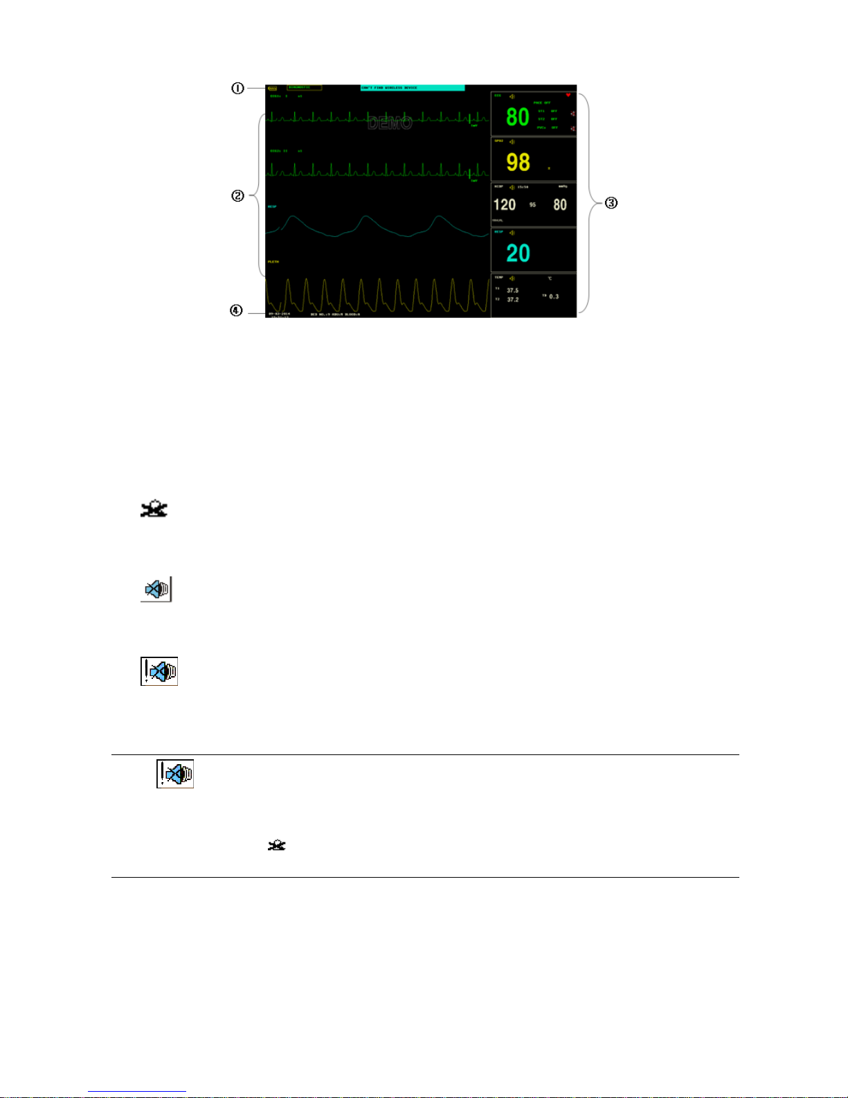
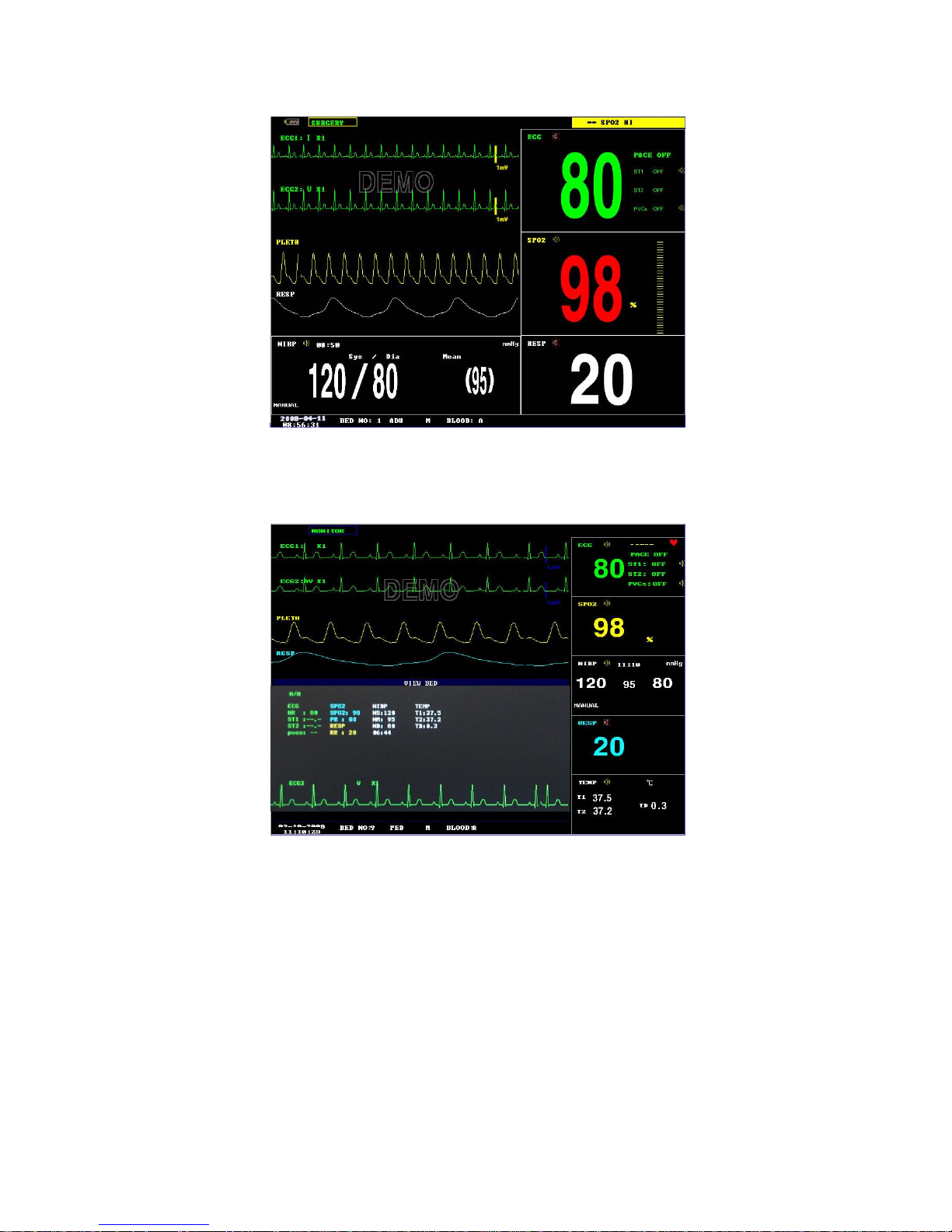
1.2 Screen Display
The display of the multi-parameter monitor is a color LCD, which can display the collected patient parameters,
waveforms, alarm information as well as bed number, time and monitor status, etc.
The screen is divided into three areas(Figure 1-1): Information area①④; waveform area②; parameter area③.
- 3 -
Figure 1-1 Main Display
Information Area
The Message Area is at the top and bottom part of the screen, displaying the current status of both the monitor and the
patient.
At the top(①)
Information will appear and disappear together with the reported status. According to the content, the information is
divided into:
Battery indicator
Filter way
Prompt information, reporting the current status of the monitor or sensor/probe.
flag for alarm PAUSE. Press “SILENCE” button once (less than 1 second) to mute all alarm sounds and
the flag appears at the same time. Press the button again to terminate the PAUSE status. The duration for PAUSE
status can be 1 minute, 2 minutes or 3 minutes.
flag for alarm SILENCE. Press “SILENCE” button once (more than 1 second) to manually mute all the
sounds and this flag appears at the same time. The SILENCE status terminates when you discharge the status or
new alarm occurs.
flag for Alarm Volume Off. It appears indicating that you have closed the alarm sound permanently. This
status terminates when you discharges the status.
Note
If symbol appears, the system will no longer give audible alarm sound. You must be very careful in
using this function. Two ways can be used to discharge this status. One is to set the alarm volume to an
option other than OFF in the USER MAINTAIN menu. The other method is to press SILENCE button to
make the flag turn to . And then press SILENCE again and the system will restore the normal alarm
status.
Parameter alarm information is displayed always in the upper right corner of the screen.
When the waveforms on the screen are frozen, the FREEZE prompt will appear in the bottom part of the screen.
At the bottom(④)
Patient information include:
BED NO . Bed number of patient under monitoring
Patient type Three options: Adult, Pediatric, Neonate
“01-01-2005” Current date
“07:11:17” Current time

- 4 -
M Patient sex, Male or Female
BLOOD Patient blood type
Waveform / Menu Area(②)
The waveform area can maximally display 8 waveforms. The displaying order of the waveforms on the screen can be
adjusted. For the maximum configuration, the waveforms provided by the system for selection are: 2 ECG waveforms,
SpO2 waveform, 2IBP waveforms,RESP waveform, CO2 waveform.
All the waveforms in the system are listed out in the “WAVE SETUP” menu. The user may adjust their displaying
positions. The specific method is illustrated in the part: WAVE SETUP.
The name of the waveform is displayed on the upper left part of the waveform. The user may choose ECG lead based
on the requirements. The gain of the channel are also displayed on each ECG waveform. A 1mV scale bar is also
displayed to one side of ECG waveform. The IBP waveform scale can also be selected according to the actual
requirement. In the IBP waveform area, the waveform scale is displayed. The three dotted lines for each IBP waveform
form up to down represent respectively the upper limit scale, reference scale and lower limit scale. The values of these
three scales can be set. The specific method is given in the part: Measure IBP.
When menu is wanted during screen operation, the menu always occupies the fixed position in the middle part of the
waveform area, therefore part of waveform can not be viewed temporarily. After exiting the menu, the system will
restore the original screen.
The user may set up the rate to refresh the waveform. The method to adjust the refreshing rate of each waveform is
discussed in the setup description of each parameter.
Parameter Area(③)
The parameter area lies to the right side of the waveform area, whose position basically corresponds to the waveform.
The parameters displayed in the parameter area include:
ECG
— Heart rate or pulse rate (unit: beats/minute)
— The ST analyzing result of channel 1 and 2: ST1, ST2 (unit: mV)
— PVCs(unit: times/minute)
NIBP
— From left to right, there are Systolic pressure, Mean pressure and Diastolic pressure(unit: mmHg or
kPa)
SpO2
— SpO2(unit: %)
— Pulse Rate(unit: beats/minute)(When “BOTH” item is selected)
IBP
— The blood pressure of channel 1 and 2. From left to right, there are Systolic pressure, Mean pressure
and Diastolic Pressure(unit:mmHg / kPa / cmH2O)
CO2
— EtCO2(unit:mmHg or kPa)
— INS CO2 (unit: mmHg or kPa)
— AwRR(times/minute)
RESP
— Respiration Rate(unit: times/minute)
TEMP
— Temperature of channel 1 and 2: T1, T2 and the difference between them TD. (unit: ℃ or ℉)
Alarm lamp and alarm status:
In normal status: the alarm lamp is not on.
When alarm exists, the alarm lamp flashes or lights on. The color of the lamp corresponds to the alarm level. Refer to
related chapter: Alarm.
For the details of alarm information and prompt information, refer to the related content of each parameter in related
chapter.
Warning
Always verify the self-check function of audible and visual (LED) alarms when powers on.
1.3 Button Functions
All the operations to the monitor are through the buttons and a knob at the bottom of the screen. The names of the
buttons are below them. They are:
MAIN
Whatever levels of menu the system is in, press the button and the system will always return to the main screen.

- 5 -
FREEZE
Press this button and the system will access the FREEZE status. In this status the user may review the waveform of 34
seconds. Also, the frozen waveform can be printed out. In the FREEZE status, press this button again to discharge the
FREEZE status. For detailed information, refer to related chapter: Freeze.
SILENCE
Push this button for less than 1 second to suspend alarm for maximum 3 minutes (with 1 minute, 2 minutes and 3
minutes selectable). In Alarm PAUSE status, a symbol appears in the Message Area. Push this button for more
than 1 second to mute all kinds of sounds (including alarm sound, heart beat, pulse tone, key sound). At the same time,
a symbol appears in the Message Area. Push this button again to restore all kinds of sounds and the
symbol disappears from the screen.
Note
If new alarm occurs in Alarm Silence status, the system will discharge Pause/Silence status automatically.
For specific rules, see Chapter Alarm.
The system will begin to give alarm information again once there exist alarm-triggering event. Nevertheless,
remember pushing SILENCE button can permanently shut off audible alarm sound of ECG LEAD OFF
and SpO2 SENSOR OFF alarms.
START
Press to inflate the cuff to start a blood pressure measurement. When measuring, press to cancel the measurement and
deflate the cuff.
REC/STOP
Press to start a real time recording. The recording time is set in RECORD SETUP. Press during recording to stop the
recording. For detailed information, refer to related chapter.
MENU
Press this button to call up the SYSTEM MENU, in which the user may set up system information and perform review
operation. For detailed information, refer to related chapter: System Menu and related chapter: Trend and Event.
Rotary knob
The user may use the rotary knob to select the menu item and modify the setup. It can be rotated clockwise or
counter-clockwise and pressed like other buttons. The user may use the knob to realize the operations on the screen and
in the system menu and parameter menu.
Method to use the knob to operate on the screen:
The rectangular mark on the screen that moves with the rotation of the knob is called “cursor”. Operation can be
performed at any position at which the cursor can stay.
When the cursor is in the waveform area, the user may immediately modify the current setup. When the cursor is in the
parameter area, the user may open the setup menu of the corresponding parameter module so as to set up the menu
items of the module.
Operating method:
Move the cursor to the item where the operation is wanted
Press the knob
One of the following four situations may appear:
1. The cursor with yellow frame becomes into the one with cyan frame, which implies that the content in the frame
can change with the rotation of the knob.
2. Menu or measuring window may appear on the screen, or the original menu is replaced by the new menu.
3. A check mark “√” appears at the position, indicating that the item is confirmed.
4. The system immediately executes a certain function.
1.4 Interfaces
For the convenience of operation, the different kinds of interfaces are in different parts of the monitor.
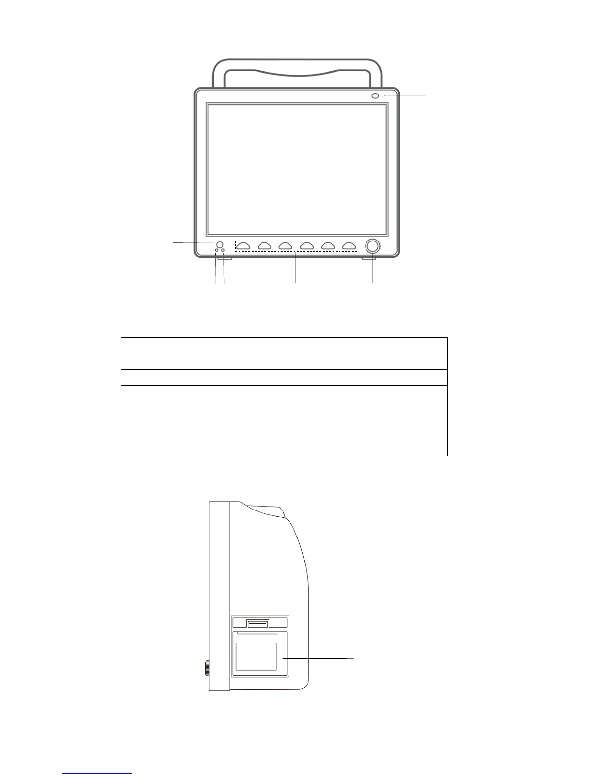
Front view
- 6 -
Figure 1-2 Front View
1
ON/OFF button
ON: press this button to turn on the device
OFF: under device on state, press this button for 3 seconds to turn it off
2
AC indicator: the device has connected to external AC power
3
Running indicator: the device is running
4
Refer to Chapter 1.3 Button Functions for details
5
Rotary knob: refer to Chapter 1.3 Button Functions for details
6
Alarm indicator: indicating different alarm level with different color and
flicking frequency
Right side view
Figure 1-3 Right Side
1
2
6
5
4
1
3

- 7 -
1
Recorder
Left side view
Figure 1-4 Left Side
1
Socket for SpO2 Sensor
2
Socket for IBP module
3
Socket for CO2 module
4
Socket for channel 1 TEMP probe
5
Socket for channel 2 TEMP probe
6
Socket for ECG cable
7
Socket for NIBP cuff
8
Battery cover
Indicates that the instrument is IEC 60601-1 Type CF equipment. The unit displaying this symbol contains an
F-Type isolated (floating) patient applied part providing a high degree of protection against shock, and is suitable for
use during defibrillation.
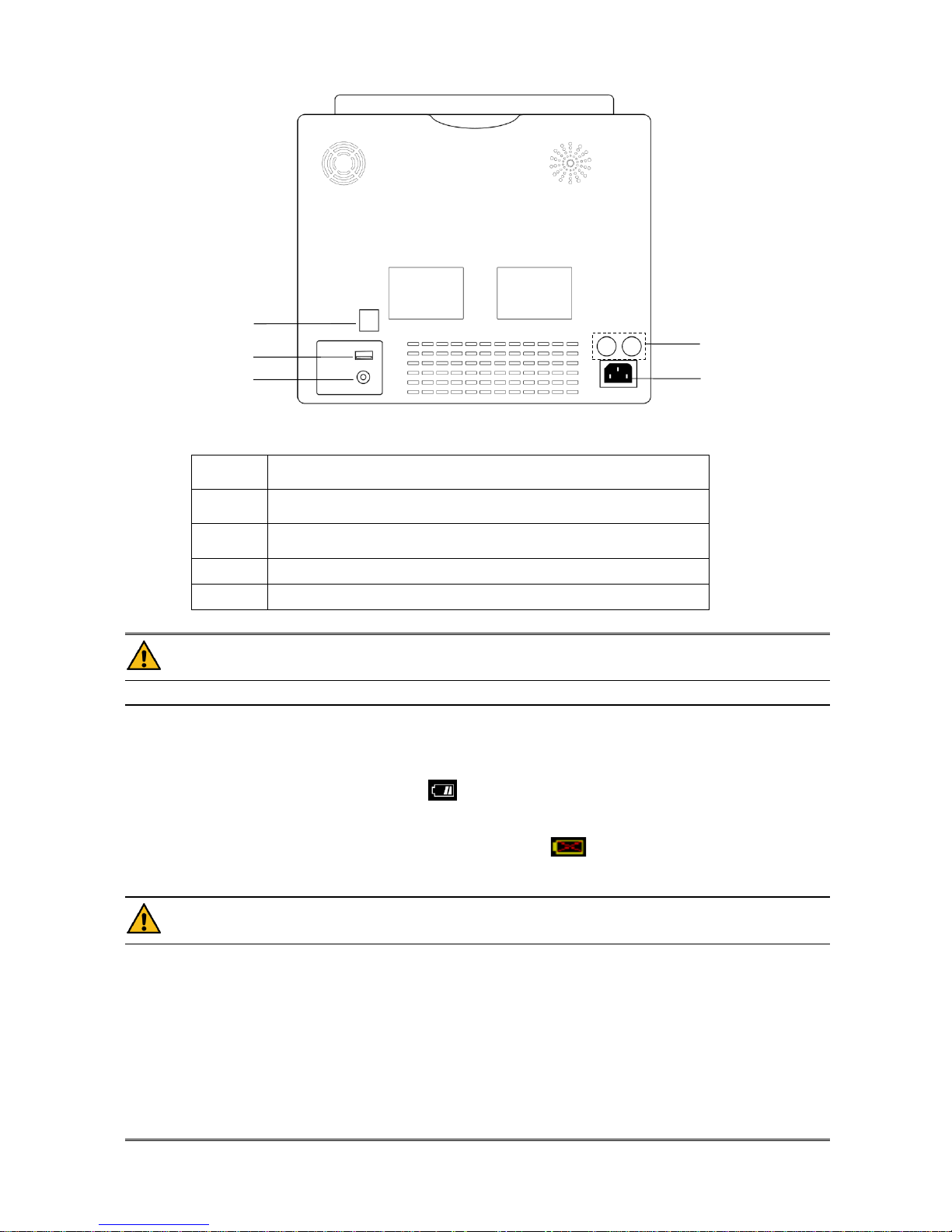
Rear view
1 2 3 4 5 6 7
8
- 8 -
Figure 1-5 Rear Panel
1
Network Interfaces, Standard RJ45 Socket, connecting with other beds
or central monitoring system through standard network cable
2
USB, used for program upgrading, SD card data storage, connecting
with central monitoring system by wireless mode
3
Equipotential grounding terminal for connection with the hospital’s
grounding system
4
Fuse T1.6AL250V
5
Power Supply,100-240V~ 50/60Hz
Warning
Through network interface only our company’s Central Monitoring System can be connected in.
1.5 Built-in Battery
The Monitor is equipped with rechargeable batteries. The battery in the monitor can automatically recharge when
connected to AC INPUT until it is full. A symbol “ ” is displayed on the upper left quarter of the screen to indicate
the status of recharging, in which the YELLOW part represents the relative electric energy of the battery. And, if the
battery is not installed in the monitor, battery state will be displayed as “ ” to indicate that no battery is available.
Under connectors to patient cables there are battery slots with cover. See Figure 1-4 Battery Slot Cover.
Warning
Don’t pull off battery during monitoring.
Remove the battery if the ME EQUIPMENT is not likely to be used for long time.
The battery shall be only applied on this device. Any maintenance or replacement upon the battery should
be processed by the service personnel trained and authorized by our company.
When operating on battery, the monitor will prompt alarm and shut off automatically when the energy is low.
When the electric energy is going out, the monitor will sound continuous level 1 alarm beeping and display
“BATTERY LOW” in the Message Area. Connect the monitor to AC power at this moment can recharge the
battery while operating. If keep operating on the battery, the monitor will shut off automatically (about 5 minutes
since alarming) upon exhaustion of the battery.
3
2
5
4
1

- 9 -
Chapter2 Getting Started
■ Open the package and check
■ Connect the power cables
■ Power on the monitor
■ Connect patient sensors
■ Check the recorder
Note
To ensure that the monitor works properly, please read Chapter Patient Safety, and follow the steps before
using the monitor.
2.1 Open the Package and Check
Open the package and take out the monitor and accessories carefully. Keep the package for possible future
transportation or storage. Check the components according to the packing list.
■ Check for any mechanical damage.
■ Check all the cables, modules and accessories.
If there is any problem, contact the distributor immediately.
2.2 Connect the Power Cables
Connection procedure of the AC power line:
Make sure the AC power supply complies with following specification: 100-240V~ 50/60Hz.
Apply the power line provided with the monitor. Plug the power line to INPUT interface of the monitor(Socket ⑥
in Figure 1-4). Connect the other end of the power line to a grounded 3-phase power output.
Note
Connect the power line to the jack special for hospital usage.
Connect to the ground line if necessary. Refer to Chapter Patient Safety for details.
Make sure that the POWER lamp now lights. If it does not light, check your local power supply. If the
problem still exists, contact the local Customer Service Center.
If the power supply is not properly connected before turning on the monitor, it may not work properly
because of insufficient power. Connect the power supply to charge the battery.
2.3 Power on the Monitor
Press POWER to power on the monitor. Then a beep will be heard and at the same time the indicator will flash once in
orange. After 10 seconds or so, the system will enter monitoring screen after self-test, and you can perform normal
monitoring now.
Note
If the monitor finds any fatal error during self-test, it will alarm.
Check all the functions that may be used to monitor and make sure that the monitor is in good status.
When the supply mains is interrupted ,the monitor will work with battery.
The battery must be recharged to the full electricity after each use to ensure adequate electricity reserve.
The interval between twice press of POWER should be more than 1 minute.
Warning
If any sign of damage is detected, or the monitor displays some error messages, do not use it on any patient.
Contact biomedical engineer in the hospital or our Customer Service Center immediately.
2.4 Connect Patient Sensors
Connect all the necessary patient sensors between the monitor and the patient.
Note
For information on correct connection, refer to related chapter 11-16.

- 10 -
2.5 Check the Recorder
If your monitor is equipped with a recorder, open the recorder door to check if paper is properly installed in the output
slot. If no paper present, refer to Chapter Recording for details.
- 11 -
Chapter3 System Menu
This monitor features flexible configurations. You can customize monitoring content, waveform sweep speed, sound
volume, and output content.
Press the MENU button on the front panel of the monitor to call up the “SYSTEM MENU”. You can perform
following operations in this menu.
Figure 3-1 SYSTEM MENU
Trend graph/table review, NIBP review and alarm review are discussed in Chapter 7 Recall.
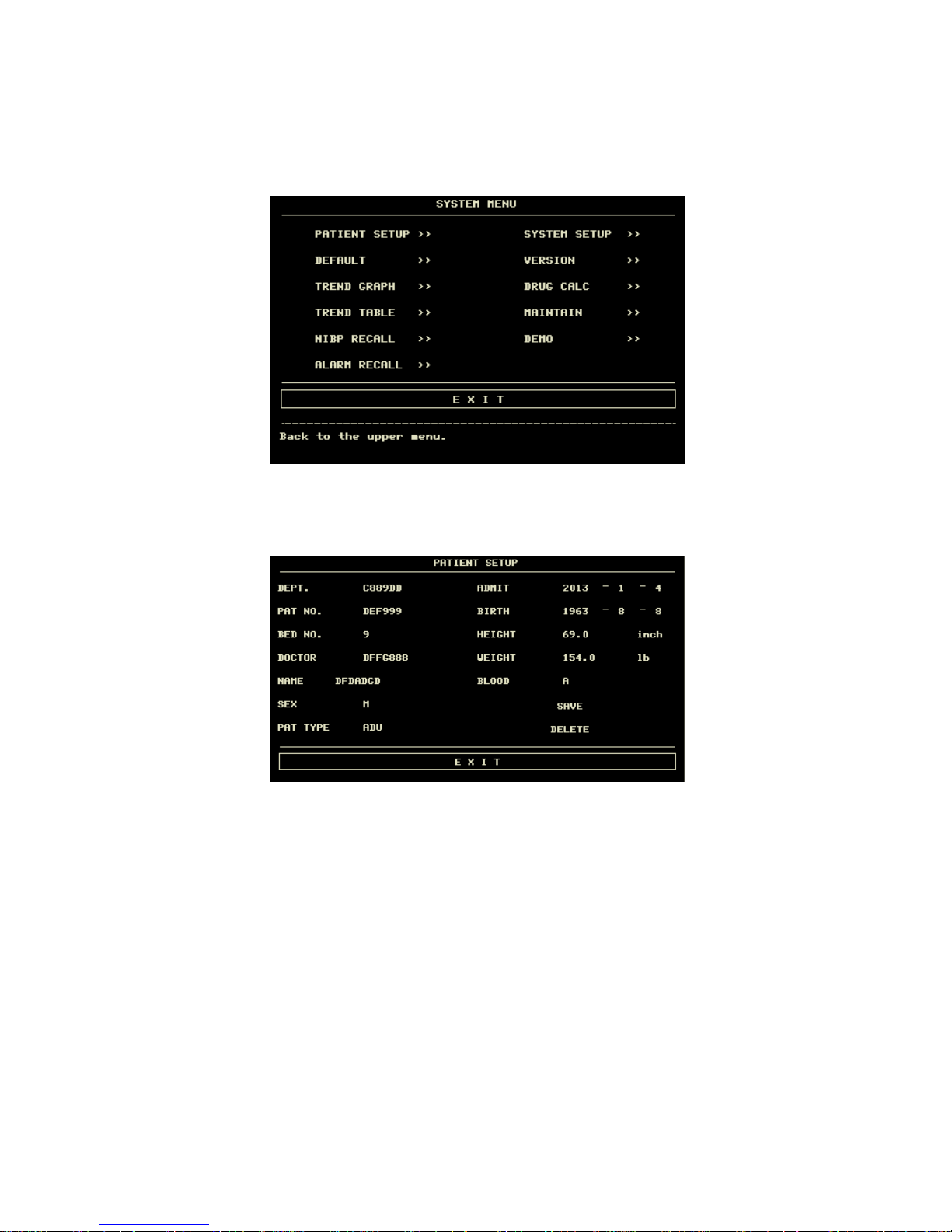
3.1 Patient Information Setup
Pick the [PAT SETUP] item in the “SYSTEM MENU” to call up the following menu.
Figure 3-2 Patient Setup
- 12 -
You can setup following patient information:
DEPT.
Department in which the patient receives treatment.
PAT NO.
Patient No.
BED NO.
Patient bed number (Range: 1-100)
DOCTOR
Name of the doctor.
NAME
Patient name (Valid characters: A-Z, 0-9 and space bar; Max. length: 12 characters)
SEX
Patient gender (Available options: "F" for Female, "M" for Male)
PAT TYPE
Patient type (Available options: ADU, PED, and NEO)
ADMIT
Hospitalization starting date (format: year\month\ day)
BIRTH
Patient date of birth (format: year\month\day)
HEIGHT.
(cm/inch)
Patient height (turning the knob with the increase/decrease of 0.5 cm/inch each time)The
other HT. unit in the other menus accord with the unit which you choosed here.
WEIGHT. (kg/Ib)
Patient weight (turning the knob with the increase/decrease of 0.5 kg/Ib each time)The
other WT. unit in the other menus accord with the unit which you choosed here.
BLOOD
Patient blood type (Pick A, B, O, AB, or N. "N" represents unknown blood type)
SAVE
To change the patient’s information you must click this button to save.
DELETE
To initialize the Patient Setup menu.
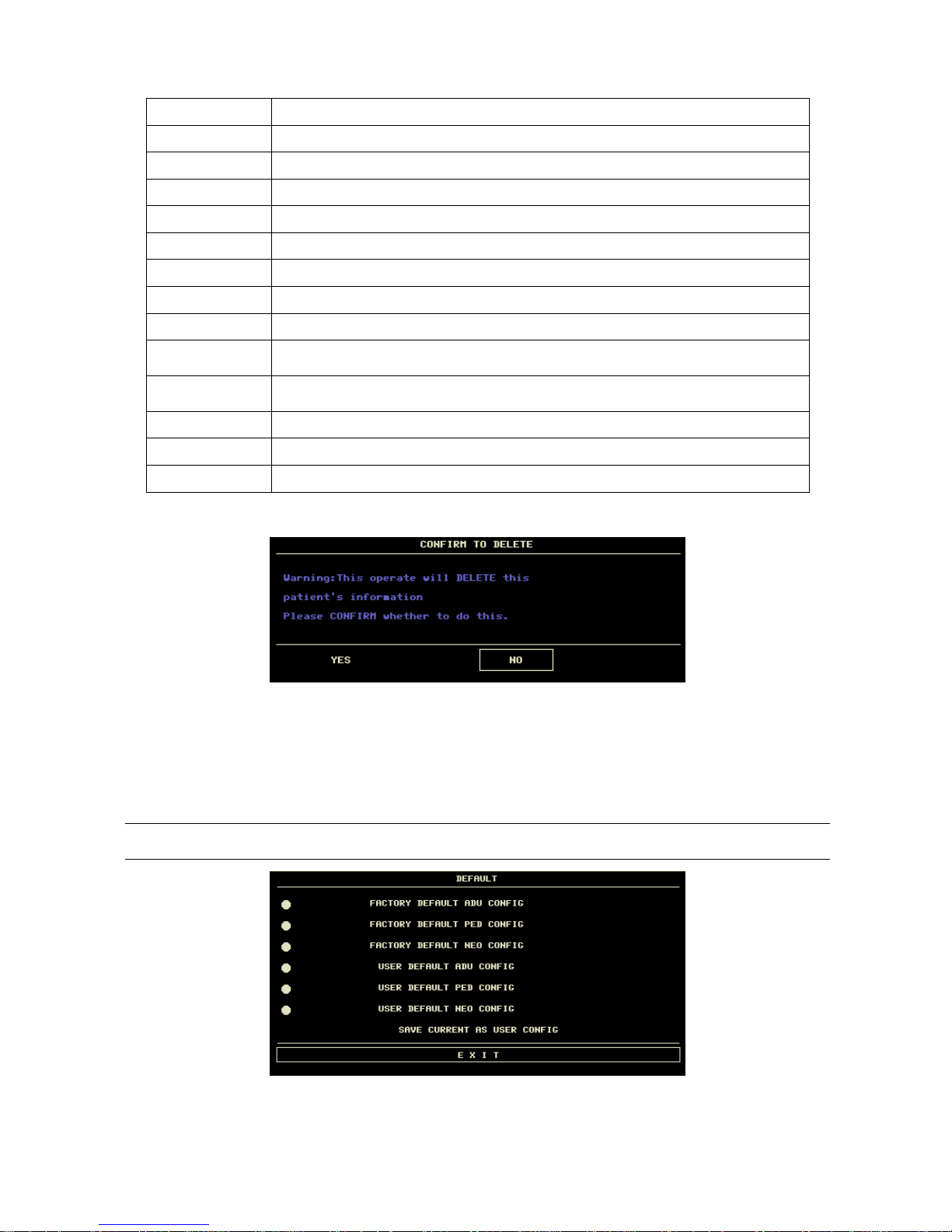
Also in this menu, you may select the [DELETE] item to access the “CONFIRM TO DELETE” dialog box as show
bellow, in which you can decide whether to clear current patient information.
Figure 3-3 Confirm to Delete
Pick [YES] to initialize the previous menu and exit the menu.
Pick [NO] to give up updating the patient and the system will keep the information of the currently patient and exit the
menu.
3.2 Default Setup
Note
After selecting any item in this sub-menu, the selected item will replace the current setup of the system and
accordingly become the system default configuration.
Figure 3-4 Default Menu
In this sub-menu, you can select both the factory default and the user-defined default. Also in this sub-menu, you can
save the current system configuration as the user-defined default configuration. But at this time, the system will
- 13 -
automatically save all the setups in the parameter menu, ECG gain and filter way as the user-defined default
configuration according to the patient type. Also, the dialog box as shown below will pop up.
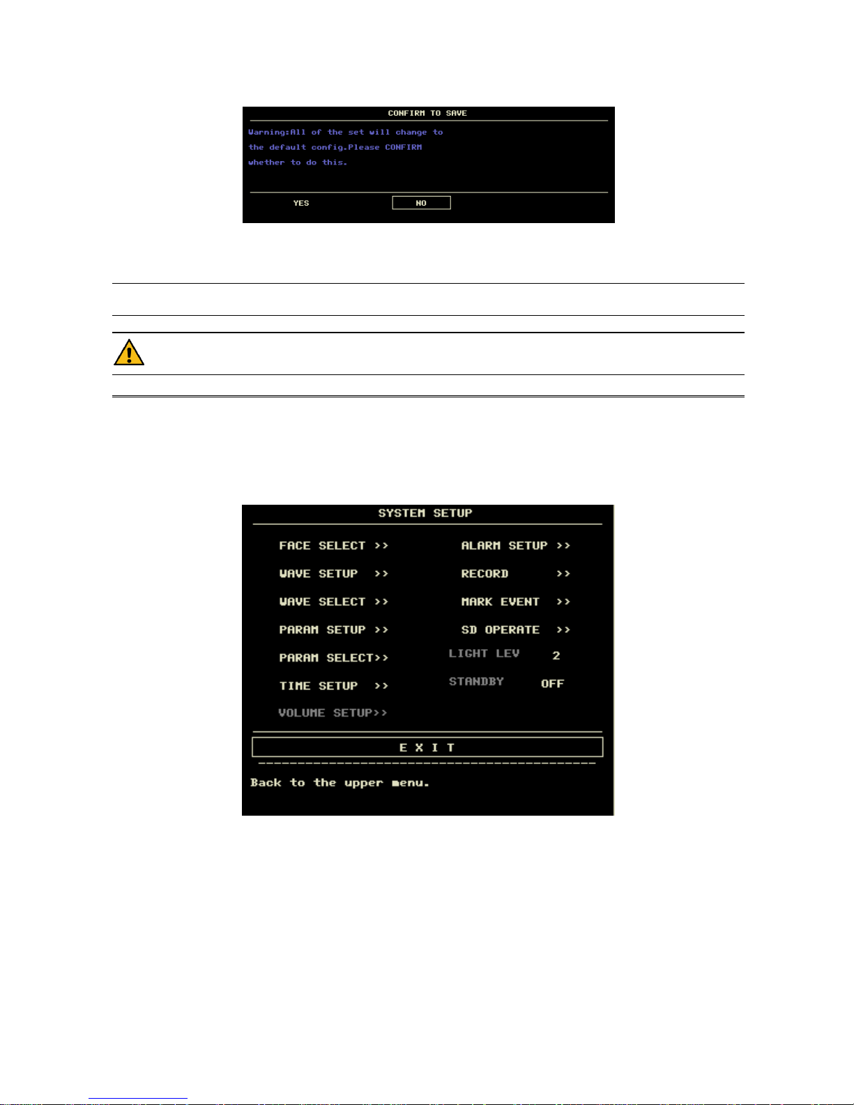
Figure 3-5 Confirm Default Config
Note
After selecting any item in the DEFAULT menu and exiting the box, the “CONFIRM TO SAVE” Dialog
box will pop up, in which you can select [YES] to confirm your selection or [NO] to give up your selection.
Warning
All configurations in the system will be replaced by “default configurations”.
3.3 Recall
In the “SYSTEM MENU”, there are [TREND GRAPH], [TREND TABLE], [NIBP RECALL] and [ALARM RECALL]
items. Please refer to Chapter 7 Recall for detailed information.
3.4 System Setup
Select the [SYS SETUP] item in the [SYSTEM MENU]:
Figure 3-6 System Setup
In the [SYSTEM SETUP] menu, users can setup the following items.
- 14 -
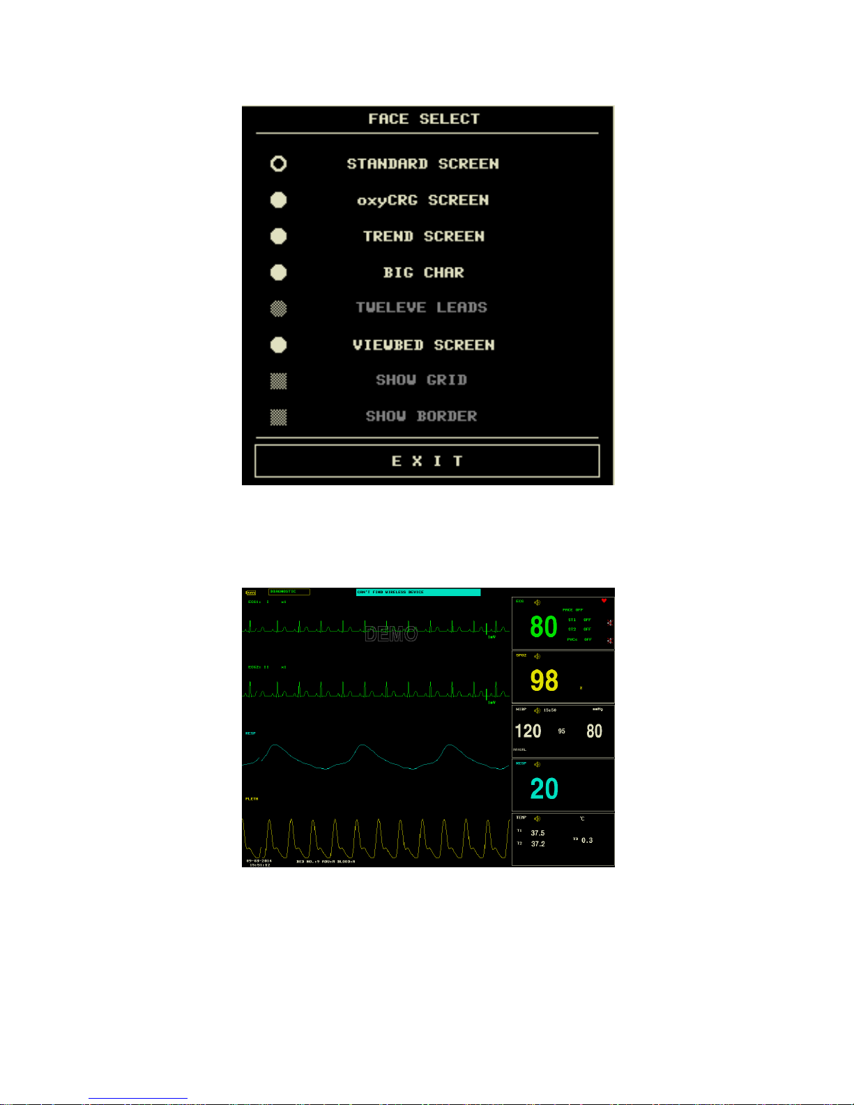
3.4.1 Face Select
Select the [FACE SELECT] item in the “SYSTEM SETUP” menu to call up the following menu:
Figure 3-7 Face Select
There are five available options:
1.STANDARD SCREEN
The standard screen is the default screen. If the current screen is not the standard screen, you may enter the standard
screen by selecting STANDARD SCREEN and then selecting EXIT in FACE SELECT menu.
Figure 3-8 Standard
2.OxyCRG SCREEN
OxyCRG screen is located at the lower part of the waveform area, consisting of the HR trend, the SpO2 trend, and the
RR (respiration rate) trend or the compressed respiration waveform. Below the RR trend or the compressed respiration
waveform is the scale of the trend time. In addition, three labels are displayed beneath the time scale. The labels are
detailed as below.
①. Trend length
This label allows you to select the time duration of the trend graphs displayed. You can select either 1 MIN, 2 MIN or 4
MIN.
②. Compressed respiration waveform/RR trend
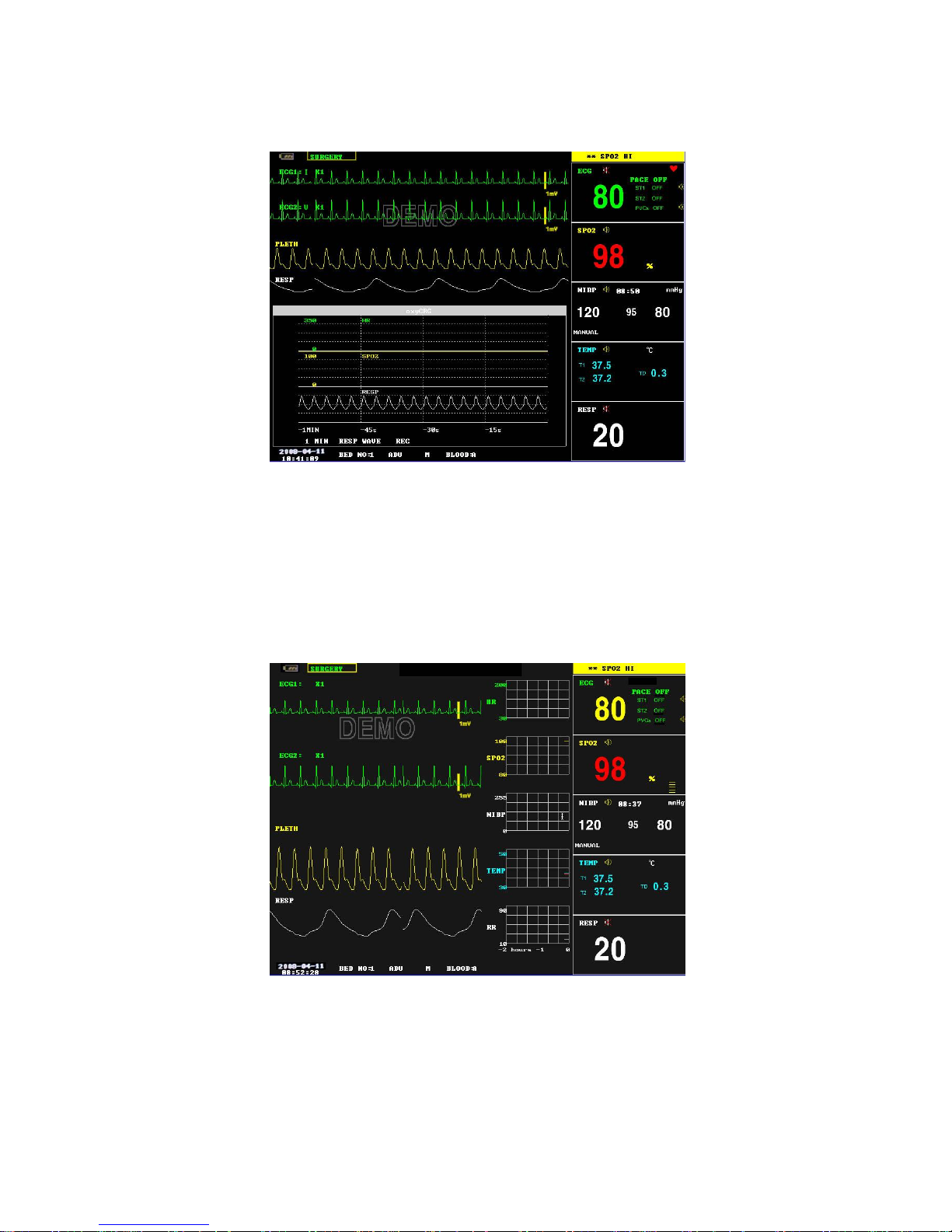
- 15 -
With this label, you can select to display the compressed respiration waveform or the RR trend beneath the SpO2 trend.
③. Recording
You can select the REC label to print out the the trends or the waveform displayed in the oxyCRG screen using the
recorder.
Figure 3-9 oxyCRG
3.TREND SCREEN
Trend graph
Trend graphs locate to the right of the corresponding waveforms in the waveform area, and display the trends of one
parameter of each module. The parameter labels,as well as their scales, are displayed to the left of the trend graph.
Trend length
The trend length, located below the trend graph, is 2 hours.
Selecting a trend parameter
If a module has multiple trend parameters, you can select one from the parameter label options of the corresponding
trend graph. The trend graph of the selected parameter will be displayed. For example, in the ECG trend graph, you can
select either from the parameter lable options: HR, ST and PVCs.
Figure 3-10 Trend
- 16 -
4.BIG CHAR
It can make you view parameter values more clear in a long distance.
Figure 3-11 BigChar
5.VIEWBED SCREEN
This monitor can view one parameter waveform and measured data from another patient monitor (viewbed monitor) on
the same monitoring network. To enter the following screen, open FACE SELECT menu, select VIEWBED SCREEN,
and then select EXIT.
Figure 3-12 ViewBed Screen
The monitor you are viewing from is called “host monitor”. The monitor being viewed is called “viewbed monitor”.
The viewbed screen is always displayed at the lower part of the host monitor’s waveform area. It consists of the
following parts.
1. Viewbed monitor label
The viewbed monitor lable allows you to select the viewbed monitor you want to view. It displays the bed number of
the viewbed monitor. If the host monitor is not connected with any other monitor on the same network, the label
displays N/A.
2. Viewbed parameter area
All parameter data of the viewbed monitor is displayed in this area.
3. Viewbed waveform label
The viewbed waveform label allows you to select a waveform of the viewbed monitor. If the viewbed monitor does not
dispaly any waveform, this label displays N/A.
4. Viewbed waveform area
The viewbed waveform area is located beneath the viewbed waveform label. It displays the waveform selected through
the viewbed waveform label. Information relating to the viewbed waveform is shown above the waveform.
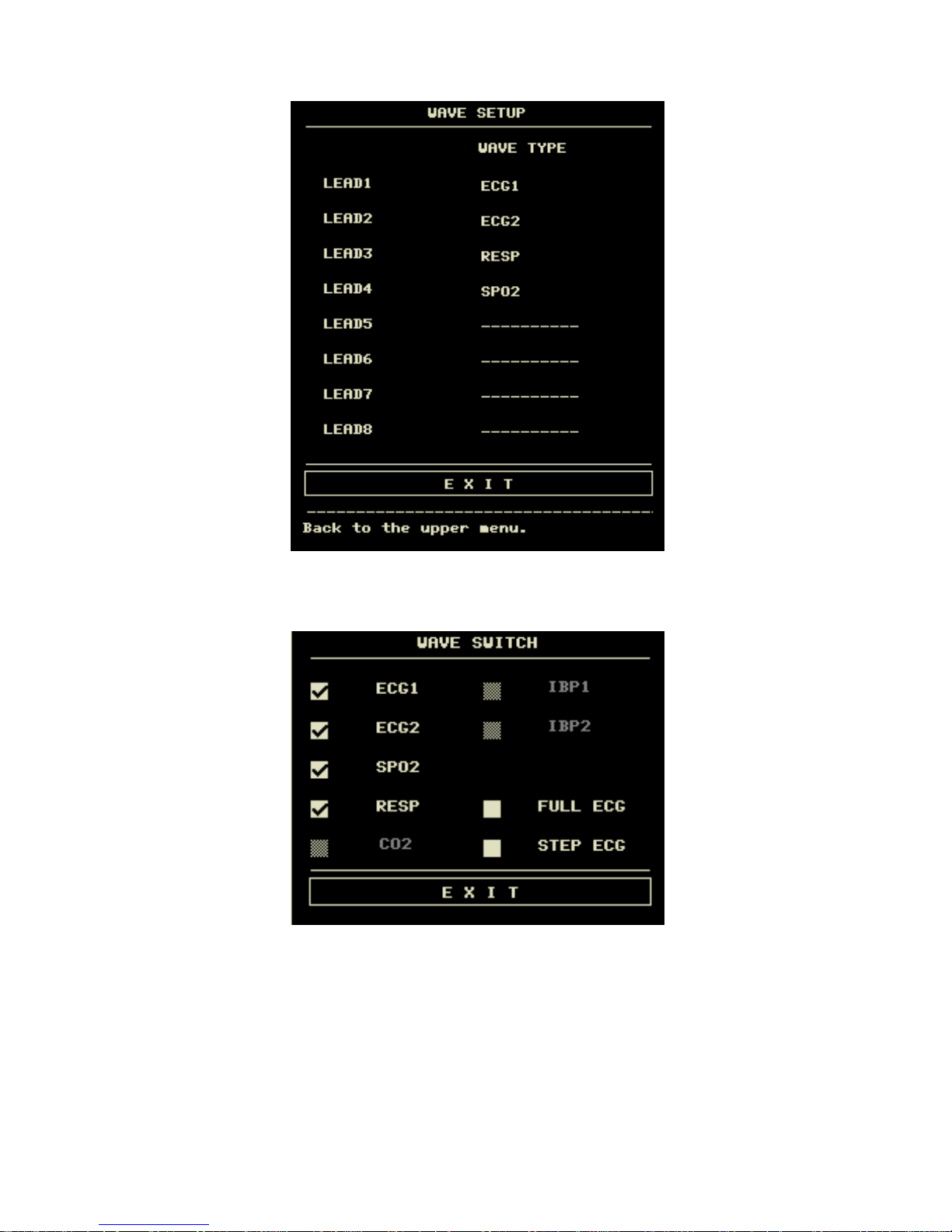
3.4.2 Wave Setup
- 17 -
Select the [WAVE SETUP] item in the “SYSTEM SETUP” menu to call up the following menu:
Figure 3-13 Wave Setup
You can change the waveforms position.
3.4.3 Wave Select
Select the [WAVE SELECT] in the “SYSTEM SETUP” menu to call up the following menu.
Figure 3-14 Waveform Select
- 18 -
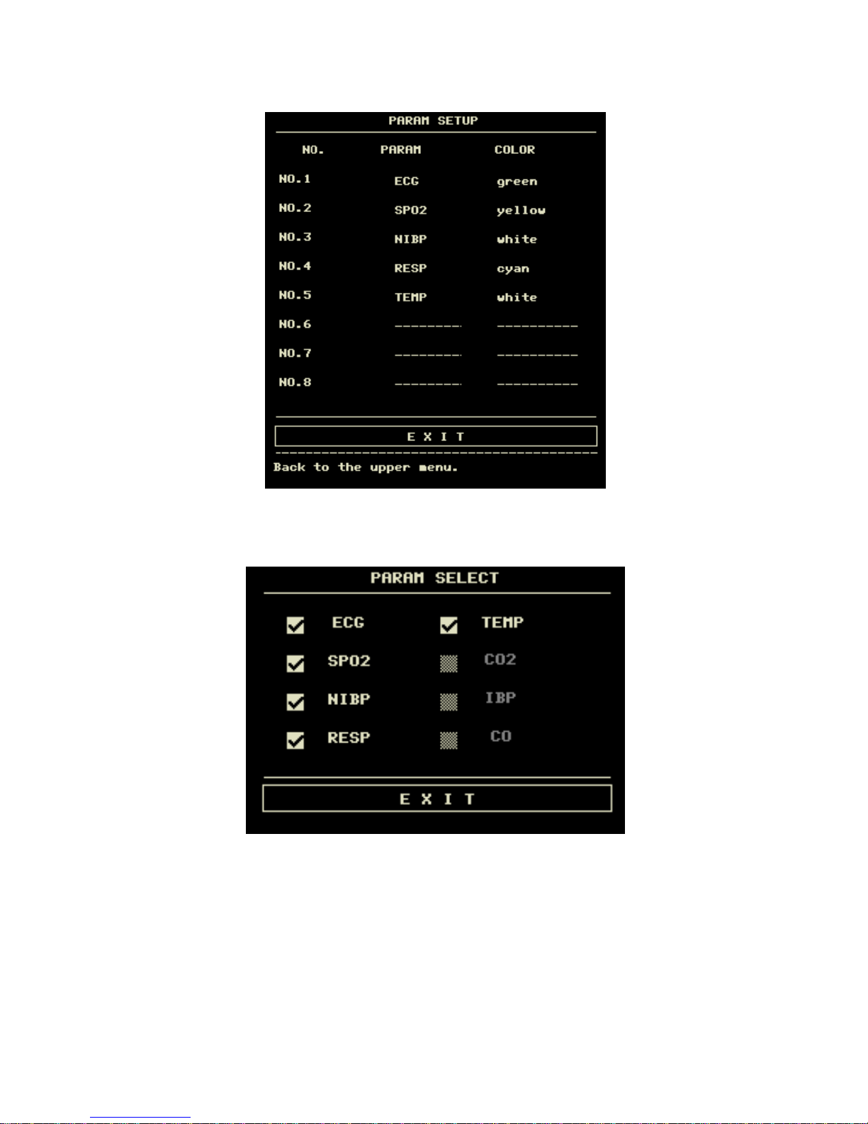
3.4.4 Param Setup
Select the [PARAM SET] item in the “SYSTEM SETUP” menu to call up the following menu:
Figure 3-15 Param Setup
You can change the parameters position and display color.
3.4.5 Param Select
Select the [PARAM SELECT] item in the “SYSTEM SETUP” menu to call up the following menu:
Figure 3-16 Param Select
You can choose the parameters to be monitored in this menu. This can avoid the interference from the parameters that
need not attention. This function can be select only when you have ordered the corresponding optional module.
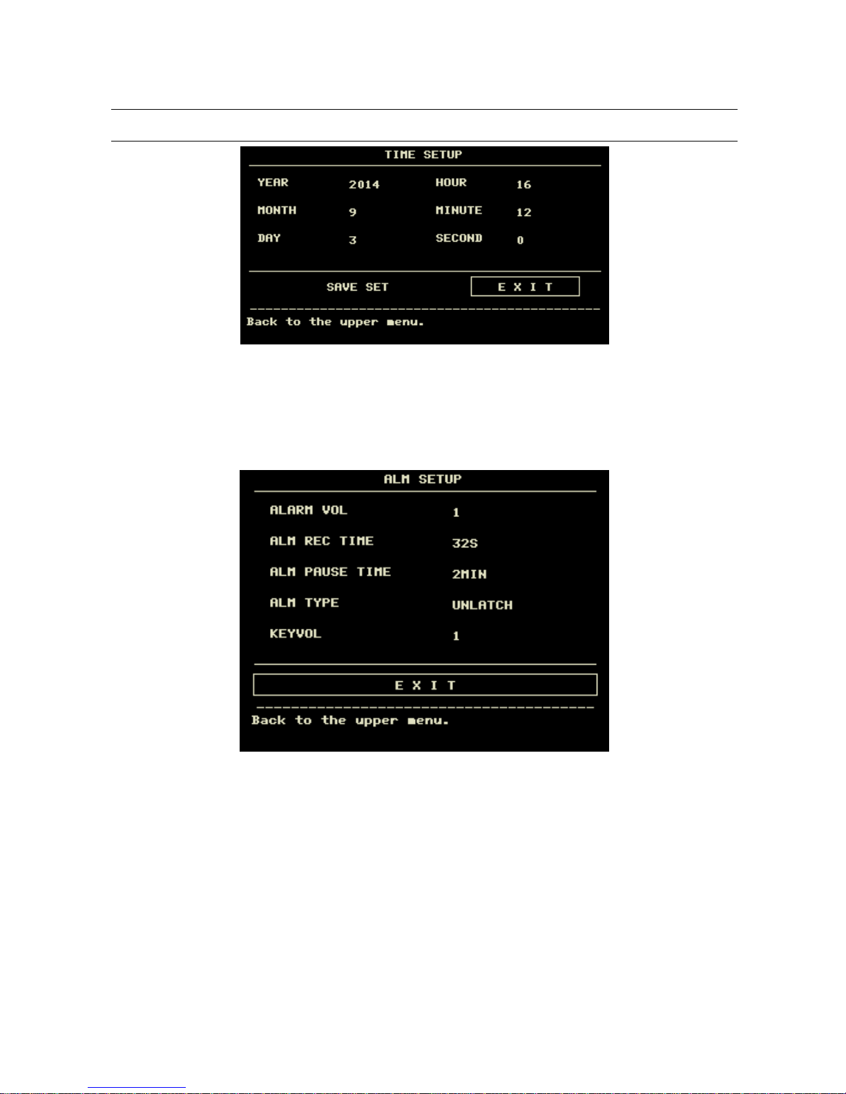
3.4.6 Time Setup
Select the [TIME SETUP] item in the “SYSTEM SETUP” menu. The menu as shown below will pop up. System time
is in the format of year, month, day, hour, minute and second. Use cursor to highlight the item that you want to modify
and turn the knob to select time. Then select [SAVE SET].
- 19 -
Note
You shall set up the system time upon turning on the monitor (if you need to set up the system time);
otherwise, when you review the content with time information, the system may not display the correct time.
Figure 3-17 System Time Setup
3.4.7 Alarm setup
The system provides 7 levels of alarm volume. You can select any of them as per the clinical requirement. The
procedures are:
Select the [ALARM SETUP] item in the “SYSTEM SETUP” sub-menu of the “SYSTEM MENU” menu. The menu as
shown below will pop up, in which you can set up the alarm volume and other alarm information. For detailed
information, refer to Chapter Alarm.
Figure 3-18 Alarm Setup
You can highlight the [ALARM VOL] item and then turn the knob to set up the alarm volume. There are 7 options:1~7.
- 20 -
3.4.8 Record setup
Select the [RECORD] in the “SYSTEM SETUP” menu to call up the following menu:
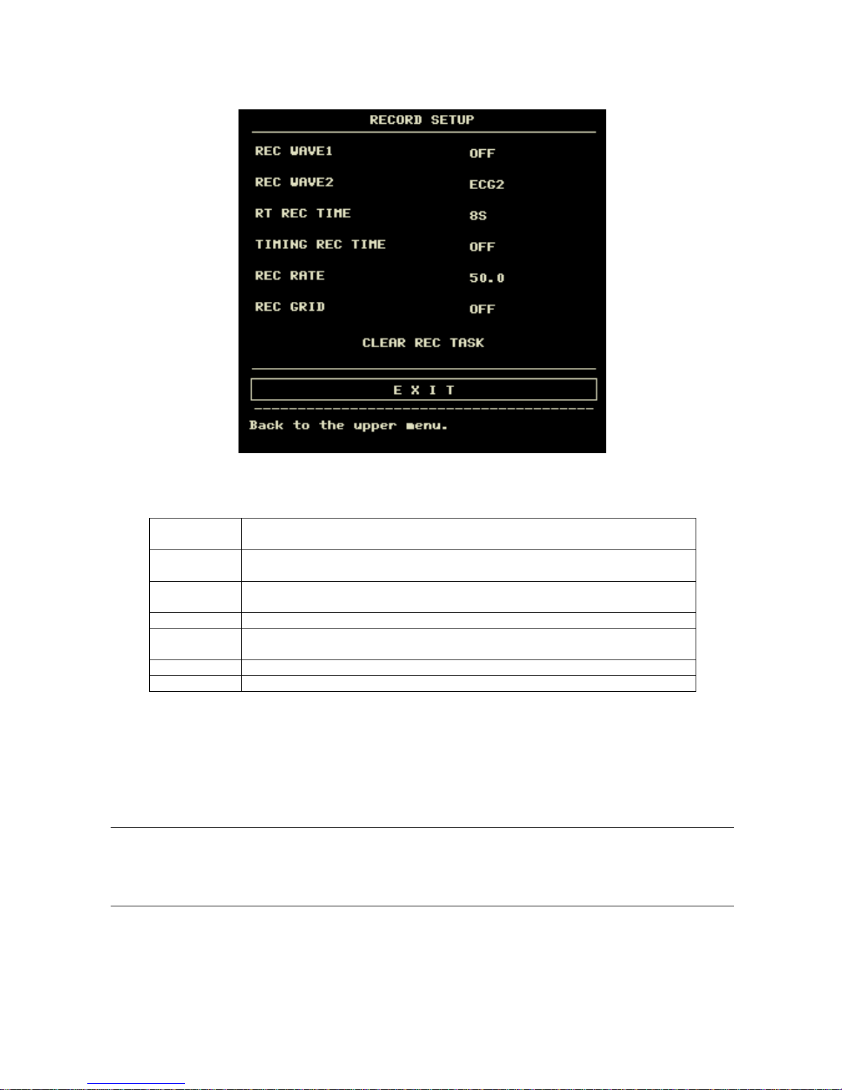
Figure 3-19 Record Setup
In this menu, the user can set up to output two waveforms. The waveforms that can be selected include:
ECG1-ECG2
Two ECG waveforms on the screen (If no ECG waveform is currently displayed on
the screen, this item cannot be picked).
SpO2
SpO2 Plethysmogram.(If no SpO2 waveform is currently displayed on the screen,
this item cannot be picked).
RESP
RESP waveform (If no RESP waveform is currently displayed on the screen, this
item cannot be picked).
CO2
Displayed waveform either of anesthetic or gas or generated by CO2 module.
IBP1
The first IBP waveform on the screen.(If no IBP waveform is currently displayed on
the screen, this item cannont be picked)
IBP2
The second IBP waveform on the screen(If less than two IBP waveforms)
OFF
No display for this waveform.
RT REC TIME this item has two options, CONTINUAL and 8s. “CONTINUAL” means once pushing the
“REC/STOP” button on the recorder panel or the monitor panel, the recorder will continuously print out the
waveform or parameter until this button is pushed again.
TIMING REC TIME OFF used to set up the time interval between two recordings. 10 selections are available:
“OFF, 10min, 20min, 30min, 40min, 50min, 1hour, 2hours, 3hours and 4hours”. The system will start the
recording process according to the selected time interval. The recording time is always 8 seconds.
Note
RT REC takes priority over TIMING REC.
REC RATE: this item has two options, 25.0 and 50.0 mm/s.
REC GRID: used to decide output format: OFF is without grid, and ON is with grid.
CLEAR REC TASK: used to clear the alarm event that has been generated and is waiting for recording out.
If two same waveforms are selected, the system will automatically change one of the waveform to a different one.
- 21 -
3.4.9 Event Setup
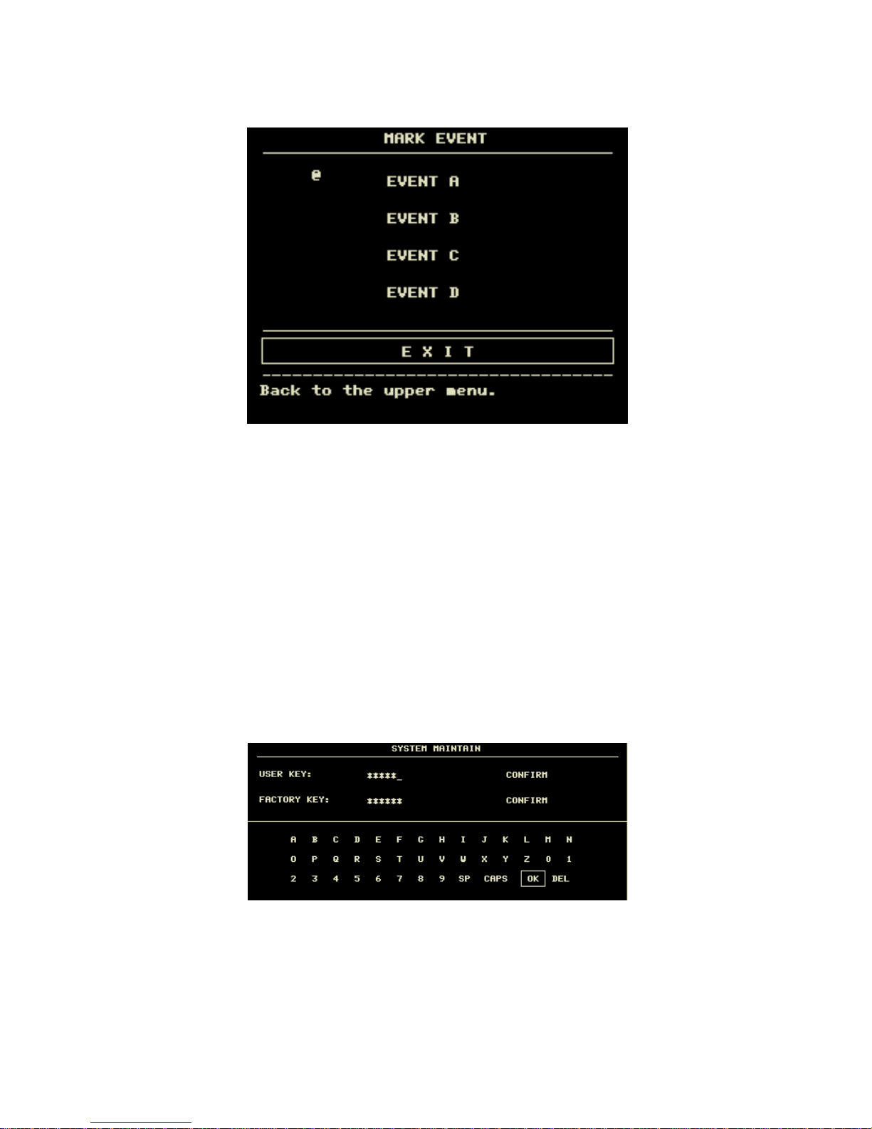
The monitor has four types of events. You can specify their representations by yourself.
Select the [MARK EVENT] item in the “SYSTEM SETUP” to call up the following menu:
Figure 3-20 MARK EVENT Menu
How to mark the event: Use the rotary knob to select one from event A, B, C and D. The @ symbol will appear in the
frame of the event being selected. Once making a wrong selection, you can push the knob on the event again to give up
the selection. Select [EXIT] to exit the menu and consequently the selection will come into effect.
Event function has following significance:
To classify the records into different categories, such as those having influence on patients and those having influence
on parameter monitoring including dose taking, injection, therapy status. Event will be displayed on the trend
graph/table in order to assist the analysis on the patient parameters when the event happens.
3.4.10 SD OPERATE
Please refer to chapter 7 Recall.
3.5 Monitor Version
Select the [VERSION] item in the “SYSTEM MENU” to know the software version of the monitor.
3.6 Drug Calculation
You can use the drug calculation and titration table function of the monitor to calculate the concentration of 15 kinds of
drugs. Refer to Chapter: Drug Calculation and Titration Table for detailed information.
3.7 Maintenance
Select the [MAINTAIN] item in the “SYSTEM MENU” to call up the “SYSTEM MAINTAIN” dialog box as shown
below, in which you can enter password and then customize maintenance settings. You cannot execute factory
maintenance function, which is only available for the service engineers of our company.
Figure 3-21 Enter Maintain Password
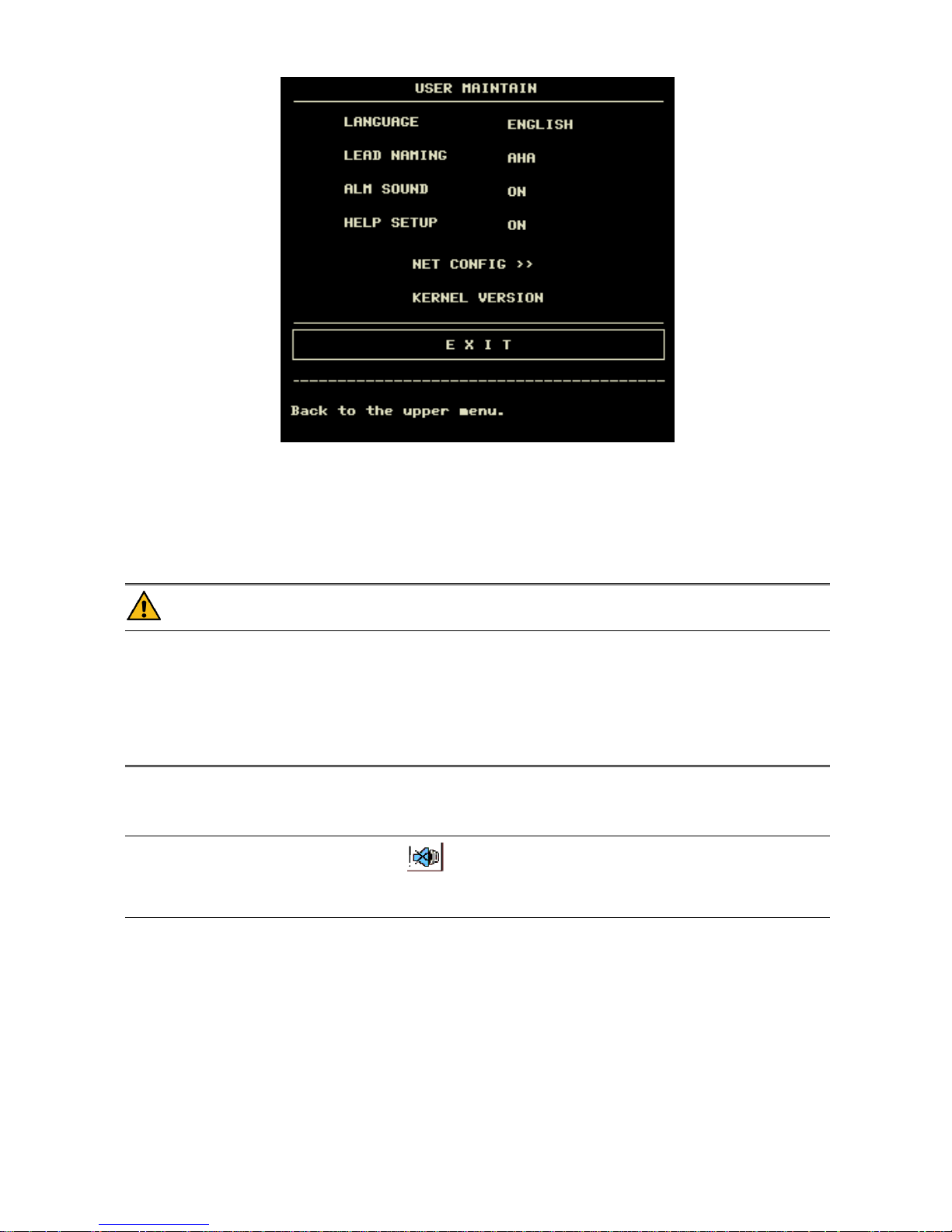
Input the password into the “SYSTEM MAINTAIN” box and press [CONFIRM], the “USER MAINTAIN” menu will
pop up, in which you can set up following items.
- 22 -
Figure 3-22 User Maintain Menu
LANGUAGE :language choice.
LEAD NAMING:AHA/EURO
ALM SOUND:ON/OFF
HELP SETUP:ON/OFF
NET CONFIG:refer to 3.7.1 NET CONFIG
KERNEL VERSION:this is used to see the kernel version when maintenance.
Warning
When the alarm volume is set to “OFF”, you will not hear the alarm sound if new alarm occurs. Therefore,
you must be very careful in using this selection.
If setting the alarm volume to “OFF” when the system is in Silence or Pause status, the system will
automatically discharge Silence or Pause status.
If you select “Silence” or “Pause” when the alarm volume is set to “OFF”, the system will restore the alarm
volume before the alarm volume is set to “OFF” and enter Silence or Pause status.
Note
After the alarm volume is set to OFF, a symbol will appear in the Technical Alarm Area.
Setting Alarm Volume to “OFF” is valid only when the monitor is turned on for this time. After turning on
the monitor next time, this setup will restore its value of the previous time when the system is turned on.
- 23 -
3.7.1 NET CONFIG
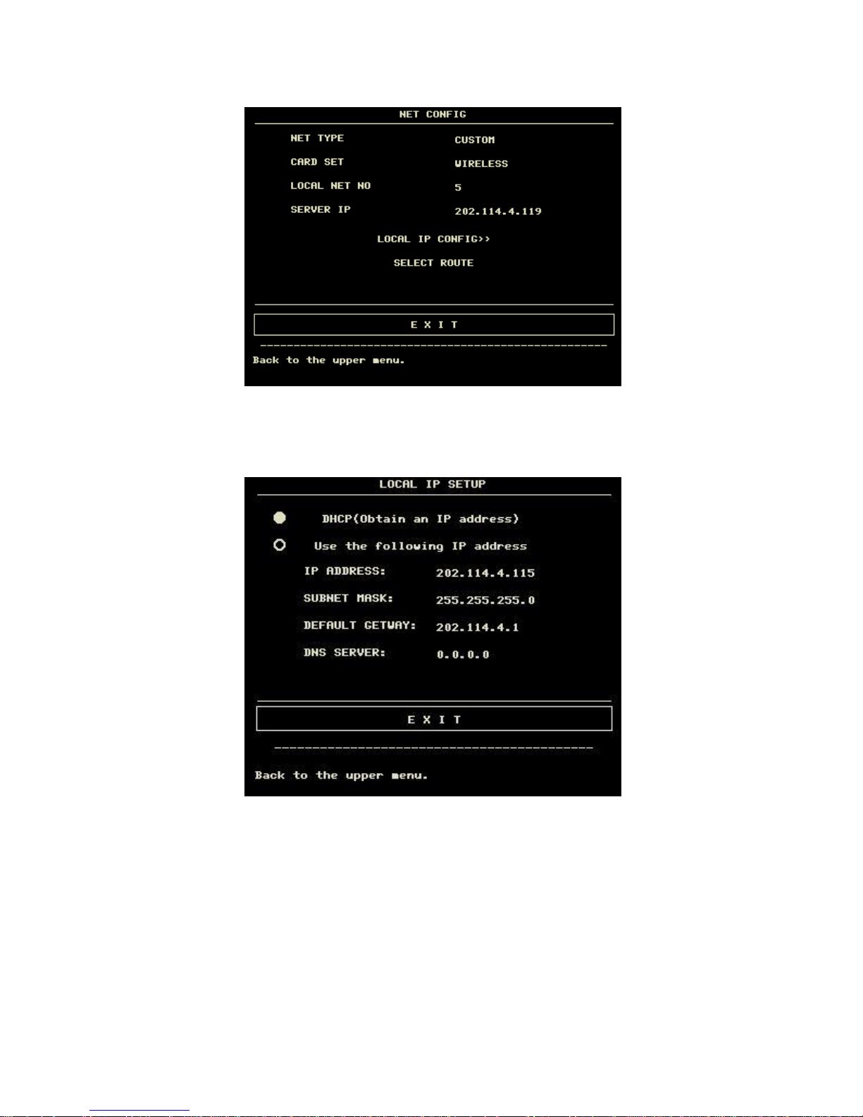
Press "NET CONFIG"to pop the following menu:
Figure 3-23 NET CONFIG
NET TYPE:CMS/CUSTOM
CMS:the Server IP is fixed, "202.114.4.119","LOCAL IP CONFIG" is unavailable.
CUSTOM:when this item is selected, CMS and machine's IP can be changed as you need.The following is "LOCAL IP
SETUP"menu.
Figure 3-24 LOCAL IP SETUP
CARD TYPE:3G,wireless and wire
3G
It is strongly required to use the accompanying 3G bracket provided by manufacturer. CDMA2000 is appointed
network, but WCDMA can be ordered.
After selecting 3G network, restart the device, then the device will obtain WAN (dynamic ip, DNS, etc.) from 3G card
and its driver.
Only when the net type is "CUSTOM" 3G is available.
Wireless
It is strongly required to use the accompanying wireless network card provided by manufacturer. Link router complied
with IEEE802.11(ordinary or household wireless network router). Support the certification mode for WPA, WPA2 or
WEP. Wireless network router links to Internet by WAN.
After selecting wireless network card, press "WIRELESS CONFIG" in "NET CONFIG" menu. "WIRELESS
CONFIG" menu appears,press "SEARCH ROUTES",the following menu appears.
 Loading...