

ConTech Lighting TLT12V3 16CR User Manual
For ConTech Lighting Standard, High, and Super High Output Tapelight Series; White, RGB and Single Color
INSTALLATION PROCEDURES
It is recommended to layout the system, or at least segments, before permanently installing the adhesive backed LED tape.
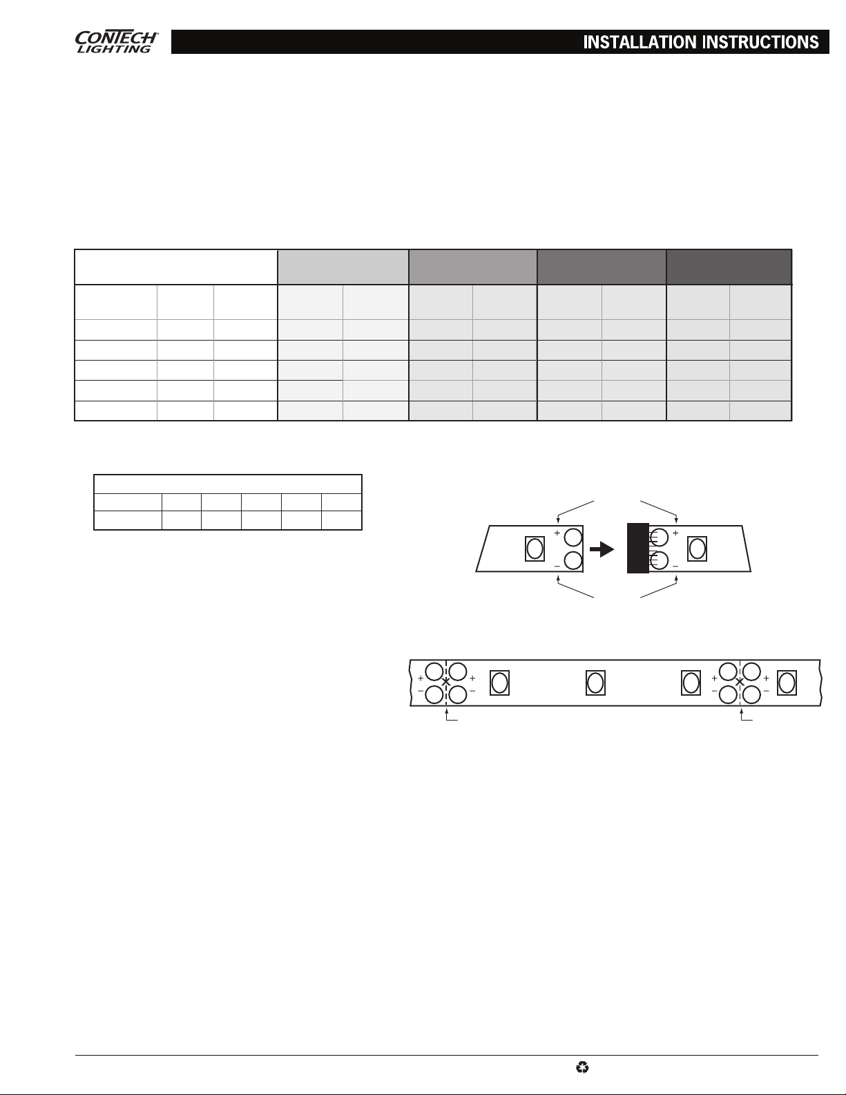
• Ensure that the power supply is sized properly for LED tape loading otherwise power supply or LED tape may be damaged. Example: the
Standard Output (SO) LED tape consumes 1.2Ws per foot. This means that a 24W power supply can effectively drive 20-feet of LED tape
(24 ÷ 1.2 = 20). Review the loading chart to determine power supply maximum load run length capabilities.
• Locate position for power supply and install in accordance with the National Electrical Code (NEC) and local codes. Review the loading chart
to determine the maximum system run length; Refer to wiring chart or power supply distance from first LED tape section to minimize the
effects of voltage drop.
A. PLUG-IN STYLE: Class 2, 120V input with 12V secondary. Install away from heat sources.
B. HARDWIRE STYLE: Class 2, 120V input with 12V secondary. Install away from heat sources. Must be maintained within an enclosure
that meets local building codes and NEC.
ConTech POWER SUPPLY
INPUT VOLTAGE: 12V DC
MODEL NO. TYPE WATTAGE
TLP12VP24 Plug -In 24W 30 ft. 20 ft. 30 ft. 13 ft. 20 ft. 6 ft. 20 ft. 6 ft.
TLP12VP36 Plug-In 36W 30 ft. 30 ft. 30 ft. 20 ft. 20 ft. 10 ft. 20 ft. 9 ft.
TLP12VP60 Plug-In 60W 30 ft. 50 ft.
TLP12VHW20 Hardwire 20W 30 ft. 16.5 ft. 30 ft. 11 ft. 20 ft. 5 ft. 20 ft. 5 ft.
TLP12VHW60 Hardwire 60W 30 ft. 50 ft.
1. Distance from first LED tape section to end of LED tape run. Exceeding this length may result in inconsistent light output from beginning to end of the LED tape run.
2. Overall distance of LED tape under load [illuminated sections]. If exceeded damage to the power supply and LED tape may result.
3. If maximum load run exceeds maximum system run, multiple runs from power supply may be employed as long as maximum load run is not exceeded.
STANDARD OUTPUT
WATTS PER FOOT: 1.2
MAX
SYSTEM
MAX
1
LOAD
2
3
3
HIGH OUTPUT
WATTS PER FOOT: 1.8
MAX
SYSTEM
MAX
1
LOAD
2
30 ft. 33.3 ft.
30 ft. 33.3 ft.
SUPER HIGH OUTPUT
WATTS PER FOOT: 3.6
MAX
SYSTEM
3
20 ft. 16 ft. 20 ft. 15.4 ft.
3
20 ft. 16 ft.
MAX
1
LOAD
WATTS PER FOOT: 3.9
MAX
2
SYSTEM
3
20 ft. 15.4 ft.
RGB
1
MAX
LOAD
2
Power Supply Wiring Chart (Copper Wire)
Wire Gauge 20 18 16 14 12
Distance* 6 ft. 10 ft. 15 ft. 23 ft. 40 ft.
*Power Supply to First LED Tape Section
Positive to Positive
• The LED tape and connectors employ a simple push in
connection system that requires no messy soldering or
Connector
crimping. Polarity must be maintained (positive to positive,
negative to negative). See markings on tape and connectors.
Negative to Negative
• The LED tape can be used directly off of a 20-foot reel as
the 4" or 12" segments are connected together. Detach two
tape segments by simply pulling them apart. Do not apply
pressure to LEDs when doing so as damage may occur.
• The LED tape can be field cut between the two sets of
connector pads as shown: every 2" for standard and high
output tape, every 4" for SHO or RGB tape. The “cut” end
Cut LinesCut Lines
of the LED tape can be inserted into other LED tape or
connectors to energize. If LED tape is cut other than
between the connector pads damage will result.
MOUNTING
• Clean mounting surface to ensure proper adhesion of LED tape.
• Carefully press LED tape onto mounting surface. Do not apply excess pressure. Avoid contact with LEDs. Do not pinch or bend LED tape
and connectors at hard angles. Bend only between LEDs.
• Optional aluminum mounting channels, end caps, and mounting clips are available. Recommended maximum distance between mounting
clips is 24" for most applications.
• Optional acrylic diffusion lens snaps into front of aluminum mounting channels.
IMPORTANT SAFETY INSTRUCTIONS:
• Read all the instructions before installation. Save instructions for later use.
• Turn off power at fuse or circuit breaker box before installation or before doing any maintenance work.
• Product must be grounded to avoid potential electric shock and any other potential hazards.
• Product must be mounted in locations and at heights and in a manner consistent with its intended use, and in compliance with National Electrical Code and
local codes. Use of accessory equipment is not recommended.
• Installing contrary to instructions may cause unsafe conditions.
• Do not block light from the trim aperture, in whole or in part, as this may cause unsafe conditions.
• Warning: Risk of fire. Most dwellings built before 1985 have supply wire rated at 60°C. Consult a qualified electrician before installation.
• To avoid hazards to children, account for all parts and properly dispose of all packing materials.
• Call the Technical Support department at ConTech Lighting with any installation questions: 847.559.5500.
www.contechlighting.com All specifications subject to change without notice.1-847-559-5500
This document can be recycled.
TLT INST
For ConTech Lighting Standard, High, and Super High Output Tapelight Series; White, RGB and Single Color
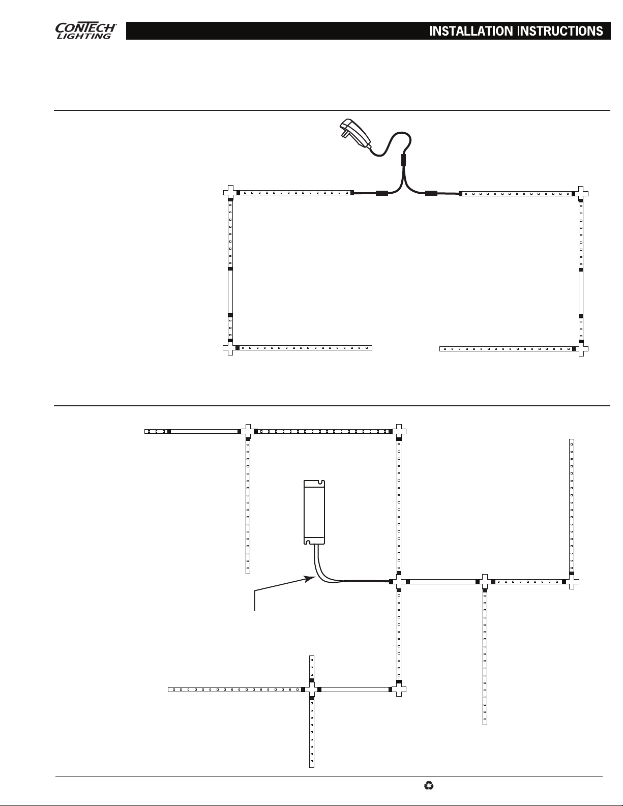
To optimize performance, it is recommended to locate the power supply in the middle of your tapelight design.
Plug-In Power Supply Layout
For RGB Tapelight applications, place
*
A Plug-In Power Supply
B Plug-and-Play 2-Way Splitter
C Input Power Connector
D Tapelight Section
E Cross Connector
F Bridge Connector
A
E
D
B
RGB controller between power source
and power connector
CC
D
E
D
F
E
Hardwire Power Supply Layout
C C
E
C
D
D
D
F
D
E
D
C
C
A
A HArdwire Power Supply
B Hardwire Input Power Connector
C Tapelight Section
D Cross Connector
E Bridge Connector
www.contechlighting.com All specifications subject to change without notice.1-847-559-5500
For RGB Tapelight applications, place
*
RGB controller between power source
and power connector
C
D
C
C
D
B
E
C
D D
C
C
D
E
This document can be recycled.
TLT INST
 Loading...