

ConTech Lighting RA44T4 User Manual
INSTALLATION INSTRUCTIONS
For RA44 Series: Mini-Recessed Stealth Housings
IMPORTANT SAFETY INSTRUCTIONS:
• Read all the instructions before installation. Save the instructions for later use.
• Follow label information and instructions concerning wet or damp locations, installation near combustible materials, insulation, building
materials and proper lamping.
• Turn off power at fuse or circuit breaker box before installation or any maintenance work.
• Product must be grounded to avoid potential electric shock or other potential hazard.
• Product must be mounted in locations in compliance with the National Electrical Code and local codes.
• Wear rubber-soled shoes and work on a sturdy wooden or other non-conductive ladder.
• Installing contrary to instructions may cause unsafe conditions.
• Do not allow items such as drapes, curtains, screens or the like to come into contact with the product as this may cause unsafe conditions.
• Warning: Risk of fire. Most dwellings built before 1985 have supply wire rated at 60°C. Consult a qualified electrician before installation.
•
To avoid hazard to children, account for all parts and properly dispose of all packing materials.
• Call the Technical Support department at Con-Tech Lighting with any installation questions: 847.559.5500.
INSTALLATION PROCEDURES
CAUTION RISK OF FIRE: Insulation must not be used in direct
contact with fixture. Provide 3" space between any part of
fixture and insulation.
MOUNTING:
1. Remove Wing Type Mounting Brackets from carton.
2. Install brackets by fitting the key hold slots over the (4)
setscrews on mounting plate. Adjust to desired length and
tighten screws.
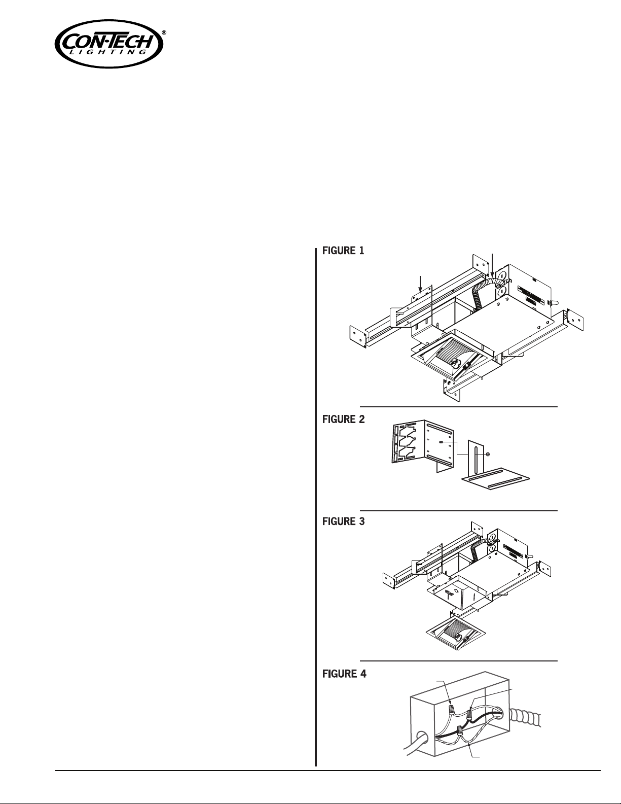
3. Mount the wing-style to the vertical slot with the open end
facing out (Figure 2)
4.
Mounting bracket will accept flat hanger bars (Con-Tech Part#
HB-24), C-channel hanger bars (provided), or 1/2" conduit
5. Plaster frame edge should be even with the finished ceiling;
wing nuts can be firmly tightened to secure mounting
bracket. (Figure 3)
6. Loosen housing set screws.
7. Adjust housing flush to finish ceiling and tighten screws.
ELECTRICAL CONNECTIONS:
WARNING: Power source must conform to the requirements
of the fixture (see labels on fixture), all NEC and
local electrical codes. Before starting the wire
connections, disconnect power at circuit breaker
or fuse, turning power off at switch leg is not
sufficient to prevent electrical shock.
1. Supply wire must be rated at 90°C or higher.
2. Connect power source to fixture junction box.
3. Connect blacks to blacks (hot), whites to whites (neutral),
and greens to greens (ground) with twist type wire connectors (not provided). (Figure 4)
4. Close junction box cover after wiring (ensure that all wires
are within box before closing).
Flexible
Wing Type
Mounting
Brackets
Conduit
.
Wing Type Mounting Brackets
LAMPING/TRIMS
1. Connect pull down trim assembly (provided) to quick
connect in housing.
2. Remove glass lens.
3. Insert lamp base into socket and turn clockwise. Install
glass lens prior to energizing. Glass must be installed prior
to operation.
4. Tuck excess wire leads into housing.
5. Trim may be mounted after ceiling is completed. (Figure 3)
6. Compress the torsion springs and place them into the slots
mounted on each end of the inside of the housing.
7. Release springs and lightly push upward, the trim will be
held firmly to ceiling surface.
www.con-techlighting.com1-847-559-5500 RA44 INST
White to White
Black to Black
Ground Wire
All specifications subject to change without notice.
 Loading...