

Page 1

INSTRUCTION MANUAL
DISSOLVED OXYGEN-METER
MODEL CDO-01
EL-221, MIDC Electronic Zone, Mhape, Navi Mumbai-400710. Tel: 022-
Page 2

61393000
CHAPTER 1
INTRODUCTION
Contech CDO-01 measures Dissolved Oxygen and temperature of liquids. It can be used
in a variety of fields such as industrial, agriculture, environmental studies and scientific
research laboratory.
ABOUT CDO-01 MODEL.
Dissolved Oxygen meter, Model CDO-01, is a microprocessor based instrument, which
measures Dissolved oxygen and salinity and temperature of a liquid under test. Meter
supports ATC (Automatic temperature compensation) feature which corrects the electrode
output changes due to temperature variation of the sample being tested. There is also an
option to enter the temperature of measuring solution manually. Also there is an option to
enter the Atmospheric Pressure for correcting changes due to it. The following are the
salient features of CDO-01 meter.
Advanced Microprocessor based design.
DO and Conductivity.
DO in Saturation % and mg/L.
DO correction for Temperature, Atmospheric pressure and Salinity.
Polarographic Electrode
Automatic and Manual temperature Compensation
Single or Multi point calibration of Salinity.
Cell Constant adjustable from 0.1 to 10.0
Temperature Coefficient adjustable from 0 to 10%/
Normalisation temperature adjustable from 15 to 30
o
C
o
C.
Bi directional RS232 interface. Baud rate selectable from 1200,2400,4800 and
9600.
Single and continuous print out of DO and Conductivity.
Multiple Printout types. Combinations selectable from Sr. No., DO/Conductivity,
Date, time and temperature.
Real Time Clock.
Temperature setting (Manual temperature compensation).
Calibration report as per GLP requirements.
LCD display with Backlight.
Memory storage of 100 measurements.
Data logging facility up to 500 results. Data logging interval selectable from 5S,
10S, 20S, 30S, 1M, 2M and 5M.
Page 3
Temperature calibration.
Atmospheric Pressure Entry.
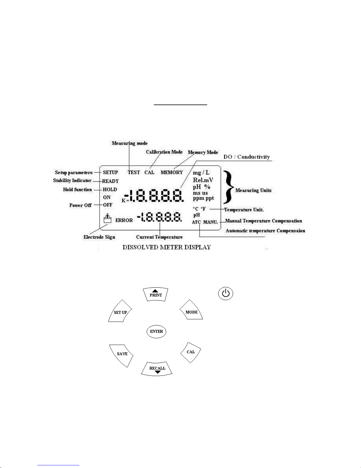
DO METER DISPLAY
CHAPTER 2
DO METER KEYBOARD
Page 4
CHAPTER 3
BASIC OPERATION AND SETUP PARAMETERS
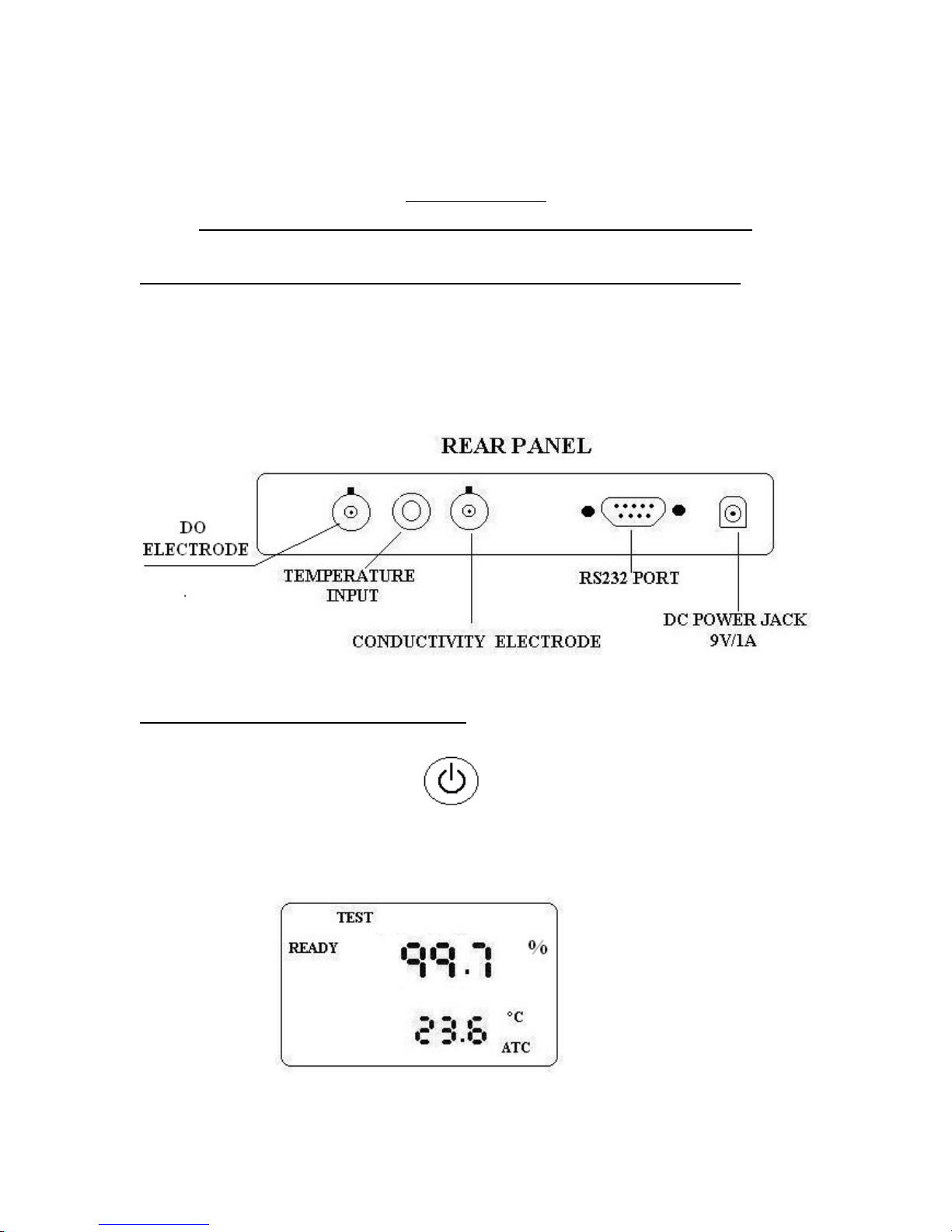
3.1 POWER AND INSTALLATION REQUIREMENTS
The meter requires good stable power. Meter is supplied with a 9V/1A switching adapter.
Connect the adaptor to the instrument to the power jack located at the rear side of the
meter. Connect the adapter to an AC power outlet. Meter is supplied with a probe.
Connect the electrode to the BNC connector provided at the rear side. Connect the
temperature probe to the temperature input connector.
3.2 STARTING THE METER
Switch on the meter by pressing the key. Instrument goes through self-tests and
subsequently display the measured Saturated DO say 99.7%.
Page 5
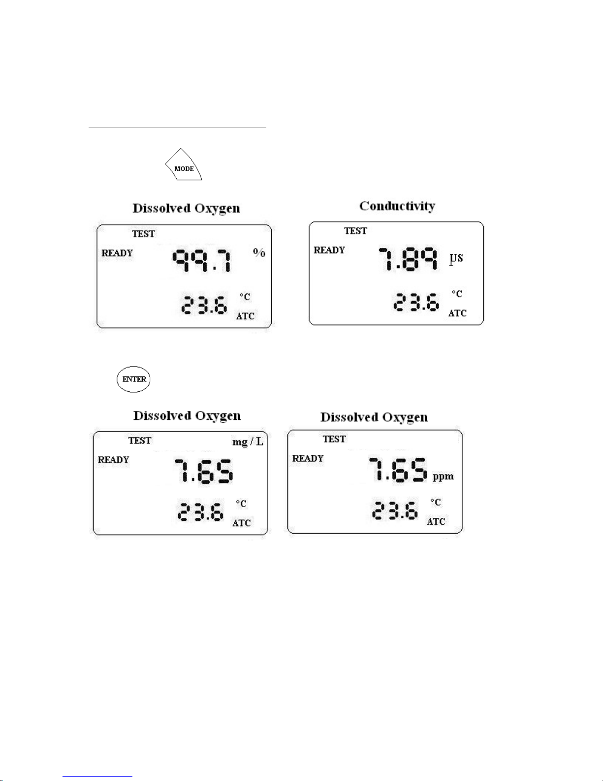
3.3 CHANGING MODES.
Use to change between DO and CONDUCTIVITY modes.
Press key to change between Saturated DO %, Do in ppm and mg/L.
3.4 SETUP PARAMETERS
3.4.1 SETTING DATE AND TIME.
Meter has an inbuilt Real Time clock. Hence there is no need to change or update date
and time. However it is possible to change date and time.
Page 6
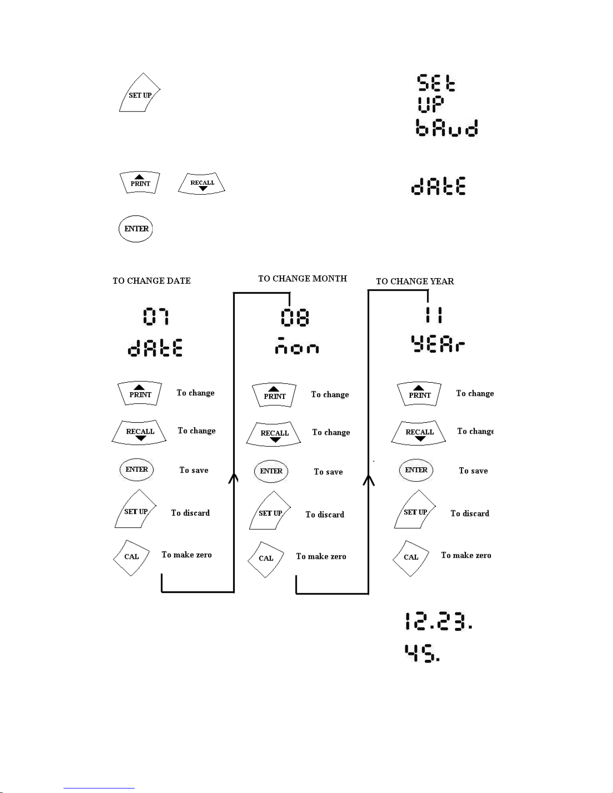
Press key. The Meter displays
and subsequently displays
Press or key till it displays
Press key. Meter displays current date say 07. Follow the instructions below for
changing date, month and year.
Meter Displays the current time, say 12.23.45
Page 7
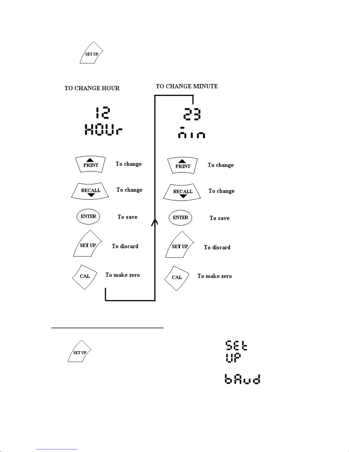
Press key to change hour. Follow the instructions below for changing
Hour and Minute
3.4.2 TO SET BAUD RATE
Press key. The Meter displays
and subsequently displays
Page 8
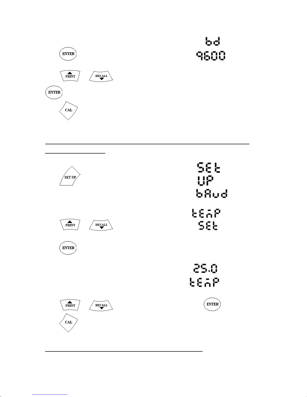
Press key. Meter displays the set baud rate say 9600.
Press or key to change between 1200, 2400, 4800 and 9600 and press
key to save.
Press key to quit without saving
3.4.3 TO SET TEMPERATURE (For Manual Temperature
Compensation)
Press key. The Meter displays
and subsequently displays
Press or key till it displays
Press key.
Meter shows the set or default temperature (25oC)
Press or key to change temperature and press key to save.
Press key to quit without saving
3.4.4 TO SET READING SERIAL NUMBER
Page 9
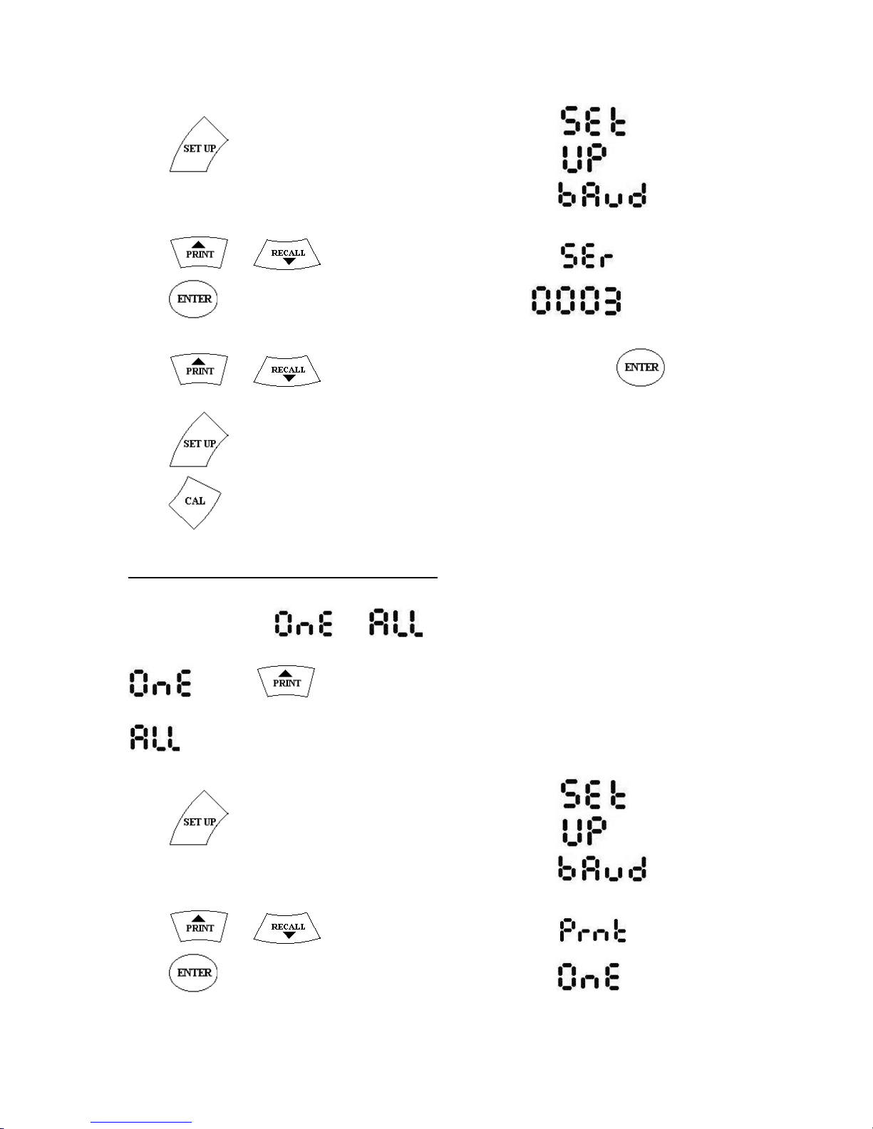
Press key. The Meter displays
and subsequently displays
Press or key till it displays
Press key. Meter shows the current serial number.
Press or key to change the serial number and press key to
save.
Press key to quit without saving
Press key to make the reading 0000.
3.4.5 TO SET PRINT OPTION
There are 2 options : and
- Press key to print current DO/Cond through RS232 port.
- Continuous data transfer to computer/printer through RS232 port.
Press key. The Meter displays
and subsequently displays
Press or key till it displays
Press key. Meter displays the current mode, say One
Page 10
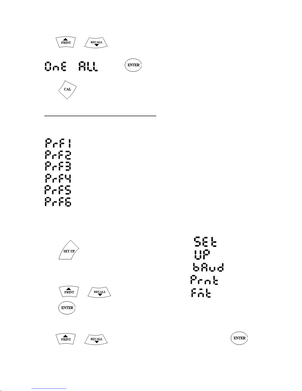
Use or keys to change between
and and Press key to save.
Press key to discard changes and quit.
3.4.6 TO SET PRINT FORMAT.
There are 6 print formats available in the meter.
- ONLY DO/Cond
- SERIAL NO, DO/Cond
- SERIAL NO, DATE,DO/ Cond
- SERIAL NO, TIME, DO/Cond
- SERIAL NO, DATE, TIME, DO/Cond
- SERIAL NO, DO/Cond, TEMPERATURE
To change the format,
Press key. The Meter displays
and subsequently displays
Press or key till it displays
Press key. Meter displays the current mode
Use or keys to change between PRF-1 to PRF-6 and press
key to save.
Page 11
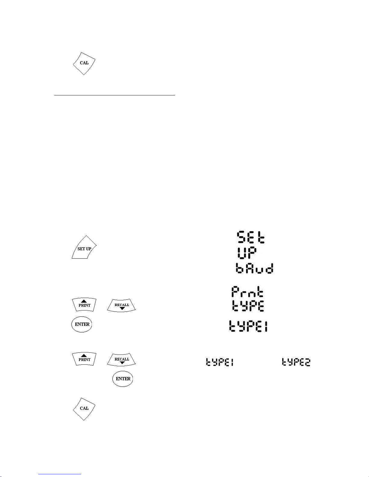
Press key to discard changes and quit.
3.4.7 . TO SET PRINT TYPE.
Meter can be set to print the results in Horizontal and vertical form
A Typical printout in the horizontal form appears as below.
1. 12.30.34 7.75 mg/L
2. 12.30.45 7.82 mg/L
While a printout in vertical mode is as shown below.
Sr.No. : 1
Time : 12.30.34
Value : 7.75 mg/L
To set the mode,
Press key. The Meter displays
and subsequently displays
Press or key till it displays
Press key. Meter displays the current mode,
say TYPE1
Press or key to change between (horizontal) and
(Vertical) and press key to save.
Press key to discard changes and quit.
Page 12
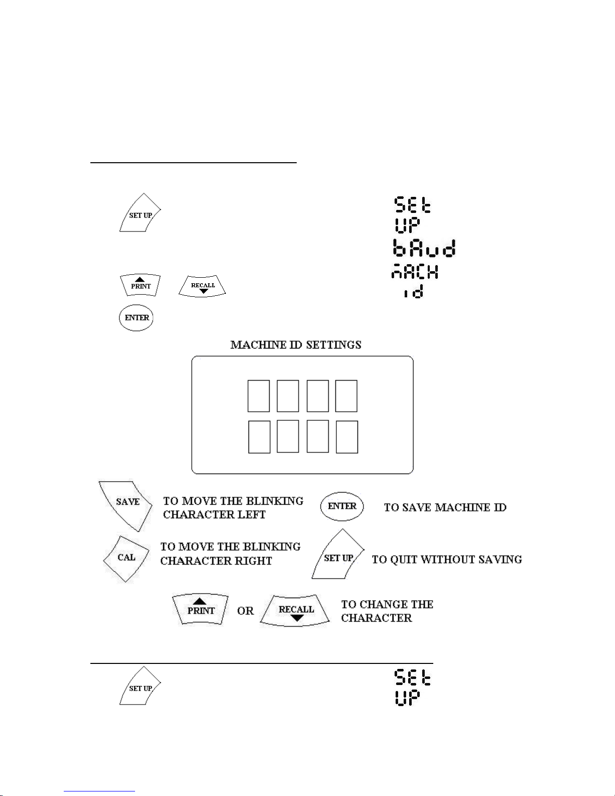
3.4.8. TO SET MACHINE ID.
Machine identification number can be assigned to the meter using this option.
Press key. The Meter displays
and subsequently displays
Press or key till it displays
Press key. Follow the instructions given below for setting id.
3.4.9. TO SET TEMPERATURE COEFFICIENT.
Press key. The Meter displays
Page 13
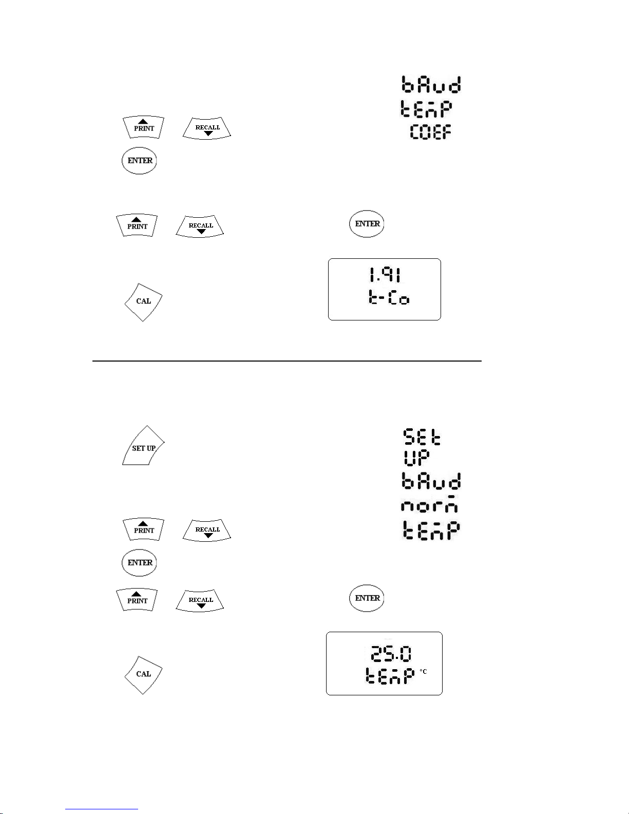
and subsequently displays
Press or key till it displays
Press key. Meter will display the current value of coefficient say 2.00
Use or key to change and Press to save.
Press key to discard changes and quit.
3.4.10. TO SET NORMALISATION TEMPERATURE.
Using Automatic temperature compensation, Meter compensates for temperature
variations of a solution from the normalization temperature set. Default normalization
temperature is 25oC. However it can be changed from 15 to 30oC, if required.
Press key. The Meter displays
and subsequently displays
Press or key till it displays
Press key. Meter will display the current value of temperature say 25
Use or key to change and Press to save.
Press key to discard changes and quit.
Page 14
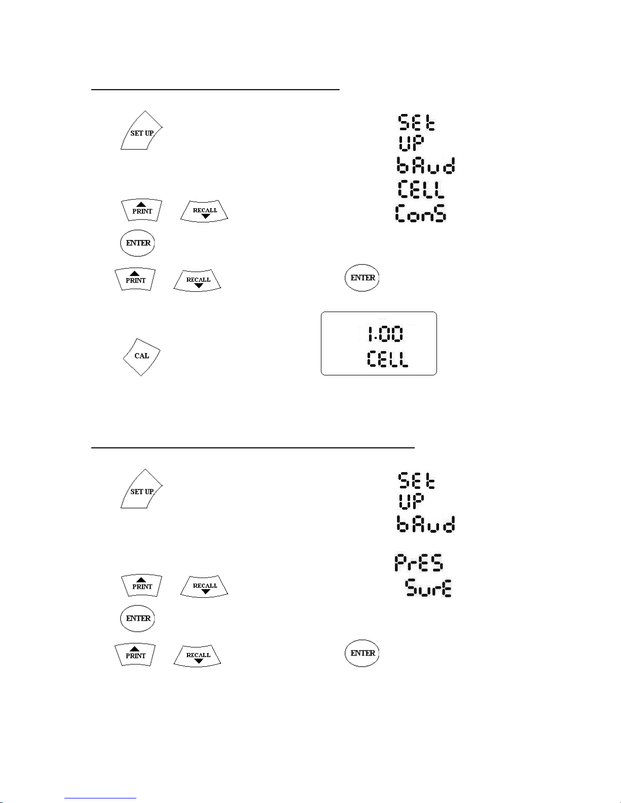
3.4.11. TO SET CELL CONSTANT.
Press key. The Meter displays
and subsequently displays
Press or key till it displays
Press key. Meter will display the current value of cell constant say 1.00
Use or key to change and Press to save.
Press key to discard changes and quit.
3.4.12. TO SET ATMOSPHERIC PRESSURE.
Press key. The Meter displays
and subsequently displays
Press or key till it displays
Press key. Meter will display the current value of atmospheric pressure say 760
Use or key to change and Press to save.
Page 15
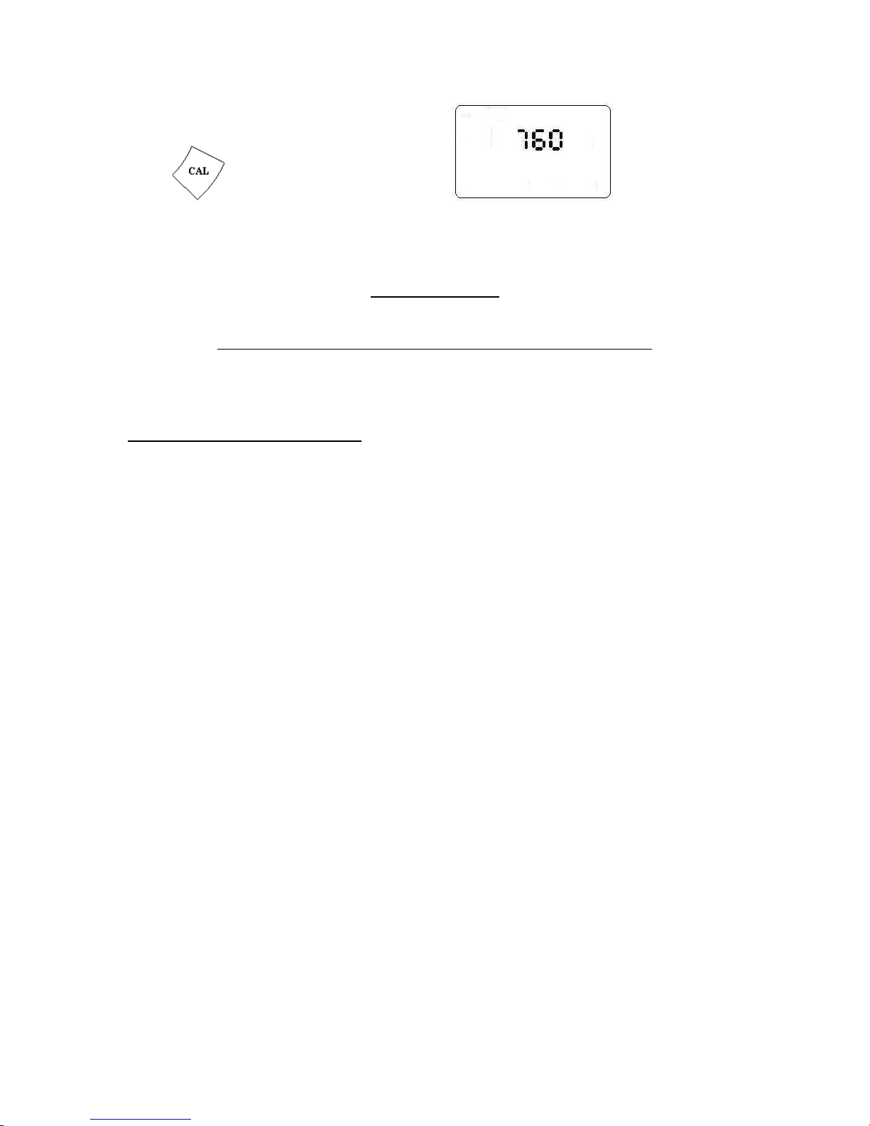
Press key to discard changes and quit.
CHAPTER 4
DISSOLVED OXYGEN MEASUREMENTS
4.1.. DO ELECTRODE.
Page 16
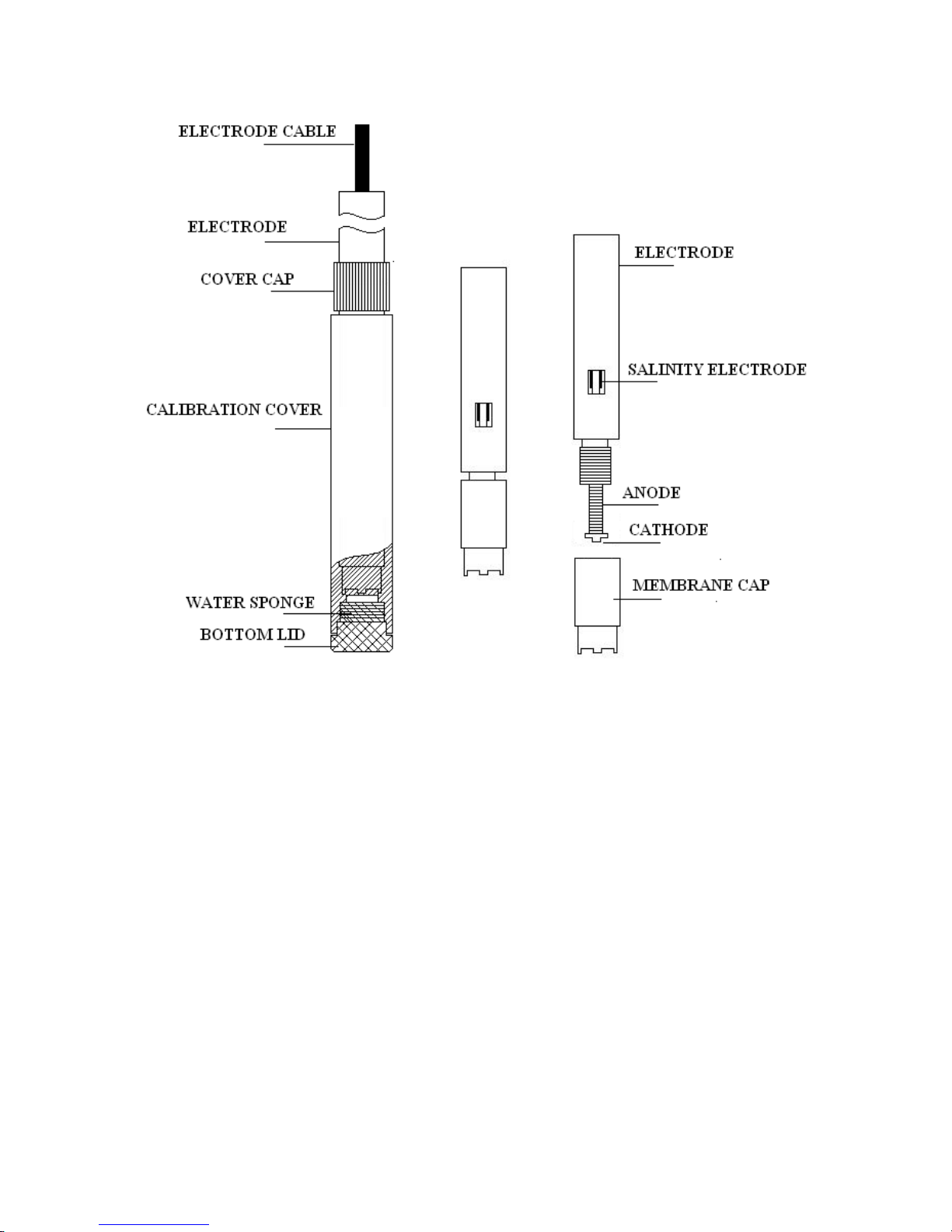
CDO-01 Electrode is illustrated above.
It is a Polarographic type electrode. It needs about 5 minutes of electrode polarization
whenever it is switched on. It has a removable electrode cap for convenience.
It has an outer calibration cover which protects the membrane cap. Unscrew the bottom
lid and check if the sponge is still soaked. If not add few drops of distilled water. Ensure
that the water is just enough to soak the sponge and it should not remain in the calibration
cover. Put the bottom lid back into the calibration cover and fix it tightly.
Remove the Calibration cap by unscrewing the cover cap.
Unscrew Membrane Cap from the electrode. Check if contains full electrode solution. If
not, add few drops of electrode solution just enough to make it full. Plug the membrane
cap back to the electrode. Whenever electrode solution is added or changed, connect the
electrode to the meter, put the meter on and polarize it for at least 15 minutes.
Page 17
Electrode also has sensors for measuring salinity. Ensure that the salinity sensor is
completely immersed in the liquid under test for effecting proper salinity correction.
4.2. DO ELECTRODE CALIBRATION.
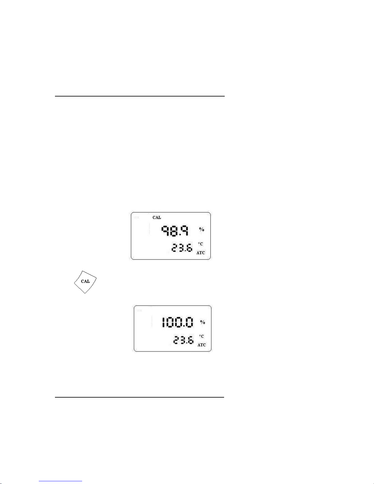
Put the meter on. Polarize the electrode for atleast 5 minutes by connecting it to the
meter. Put the meter in % Saturation Mode.
Keep the Electrode vertically to polarize for at least 5 minutes and wait for the display to
become stable.
Alternately remove the calibration cover and keep the electrode vertically for at least 5
mintes for polarization.
Wait for the display to become stable
Press key. Wait for meter to display
Electrode calibration is now complete.
4.2.1 ZERO OXYGEN CALIBRATION.
Zero Oxygen calibration is required when the electrode/electrode cap is replaced or the
meter is unused for long time. Zero oxygen calibration is done at factory and generally
Page 18
meter need not be calibrated for zero oxygen levels unless the conditions mentioned
above occur.
For zero oxygen calibration, mix 5g of anhydrous sodium sulphite (Na2SO3) into 100 ml
of pure distilled water. Mix it thoroughly to make a homogenous solution.
Polarize the electrode for 15 minutes by connecting it to the meter.
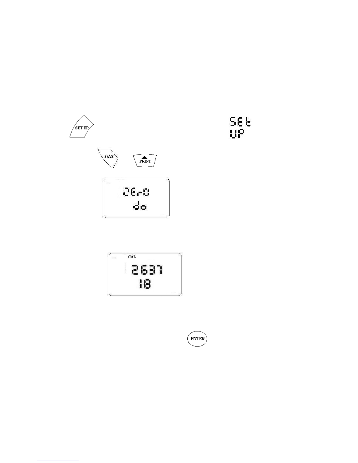
Press key. The Meter displays
Immediately press and keys together.
Meter displays
And subsequently displays the current signal value.
Immerse the DO electrode into the above zero oxygen calibration solution and keep it
polarized for about 10 minutes.
Wait for the display to become stable and Press key.
Page 19
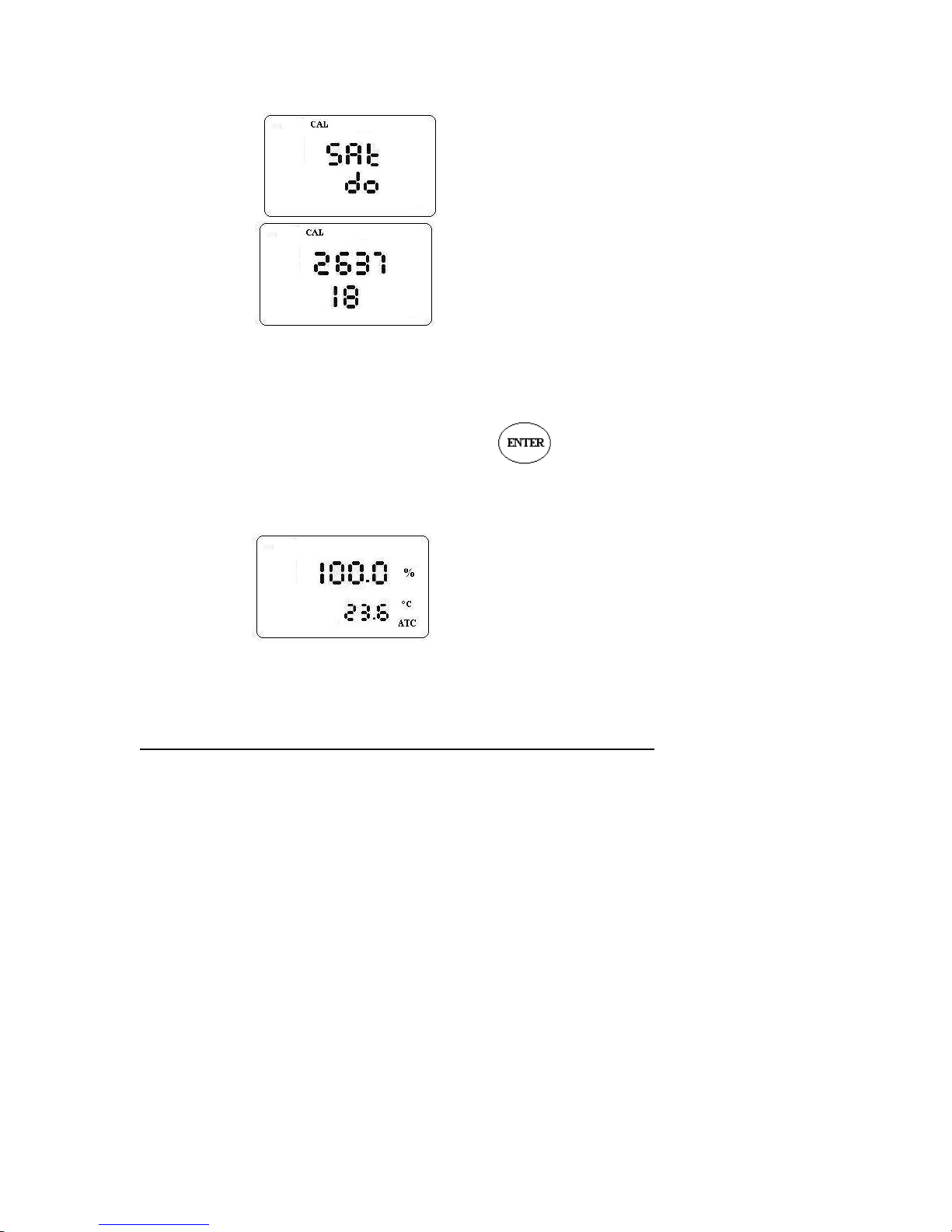
Meter Displays and subsequently displays the current signal
value.
Remove the electrode from the solution and press make it dry and hold it vertically for
about 10 minutes.
Wait for the display to become stable and Press key.
Meter is now calibrated for zero and saturated oxygen. It displays
4.3. SALINITY ELECTRODE CALIBRATION.
CDO-01 can be calibrated for salinity in both manual and auto modes. Automatic
calibration can be done in Conductivity mode only. But Manual calibration also can be
performed . Meter also allows Single and Multi point calibration.
In case of Single point calibration, when a calibration is performed in one Range,
Calibration of all the 5 ranges will be changed. However in Multi point calibration, new
calibration value will be the change in the range of the calibration solution only.
Always use fresh solution for calibration. For optimum results, choose calibration
standards close to the values being measured. Use Single point calibration, if
measurement is done in one single range. For measurements in different ranges, use multi
point calibration. While Calibration solution of 1413 uS/cm takes care of the 0 –2000 us
range, 84us/cm solution can be used for 0 – 200 us/cm or 12.88 mS/cm for 0 – 20 ms
range. As a thumb rule use a calibration solution which is atleast 60 –70% of the range.
Page 20
Calibrate the meter frequently atleast once a week for better results. There may be
situations where the meter must be calibrated before use.
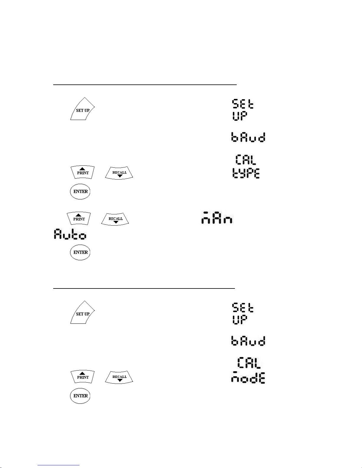
4.3.1 SETTING AUTO / MANUAL MODES.
Press key. The Meter displays
and subsequently displays
Press or key till it displays
Press key. Meter will display the current calibration type.
Use or keys to change between (Manual) and
(Auto)
Press key to select the mode.
4.3.2 SETTING SINGLE / MULTI MODES.
Press key. The Meter displays
and subsequently displays
Press or key till it displays
Press key. Meter will display the current calibration mode.
Page 21
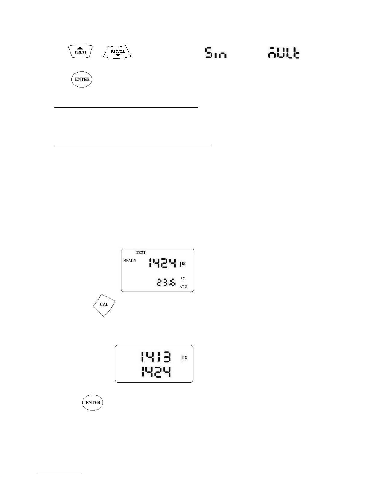
Use or keys to change between (Single) and
(Multiple)
Press key to select the mode.
4.3.3 SALINITY CALIBRATION.
Meter can be calibrated for Conductivity in Automatic and Manual Modes.
4.3.3.1 Automatic Conductivity calibration.
1. Select AUTO mode as per 4.1 above
2. Select conductivity mode.
3. Select SINGLE or MULTI mode as per 4.2 above
4. Rinse the electrode with distilled water to remove any residue of the previous
measurement. Air it dry.
5. Rinse the electrode with the Calibration Solution.
6. Immerse the electrode in the Calibration solution. Ensure that the steel ring of the
probe is immersed in the liquid. Stir the liquid gently for consistency.
7. Immerse the temperature probe also into the solution (If provided).
8. Wait for the Conductivity reading to stabilize. Say 1424 uS/cm
9. Press key.
Meter automatically recognizes the standard and displays
Press key. Meter calibrates to the new value and displays the results as below.
Page 22
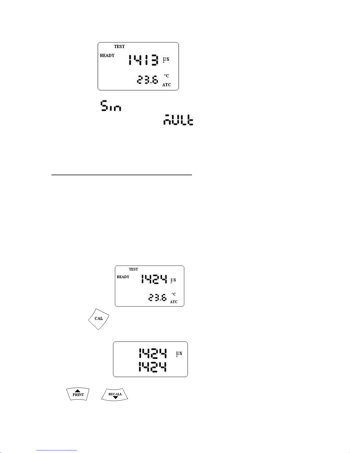
In SINGLE( ) mode calibration type, Calibration values of all the ranges
will be Changed, while in MULTI( ) mode Calibration of only the
current range ( Range 200 – 2000uS/cm) will be changed.
4.3.3.2 Manual Conductivity calibration.
1. Select MANUAL mode as per 4.1 above
2. Select conductivity mode.
3. Select SINGLE or MULTI mode as per 4.2 above
4. Rinse the electrode with distilled water to remove any residue of the previous
measurement. Air it dry.
5. Rinse the electrode with the Calibration Solution.
6. Immerse the electrode in the Calibration solution. Ensure that the steel ring of the
probe is immersed in the liquid. Stir the liquid gently for consistency.
7. Immerse the temperature probe also into the solution (If provided).
8. Wait for the Conductivity reading to stabilize. Say 1424 uS/cm
9. Press key. Meter displays
Use or key to change the value to the standard value, say 1413
Page 23
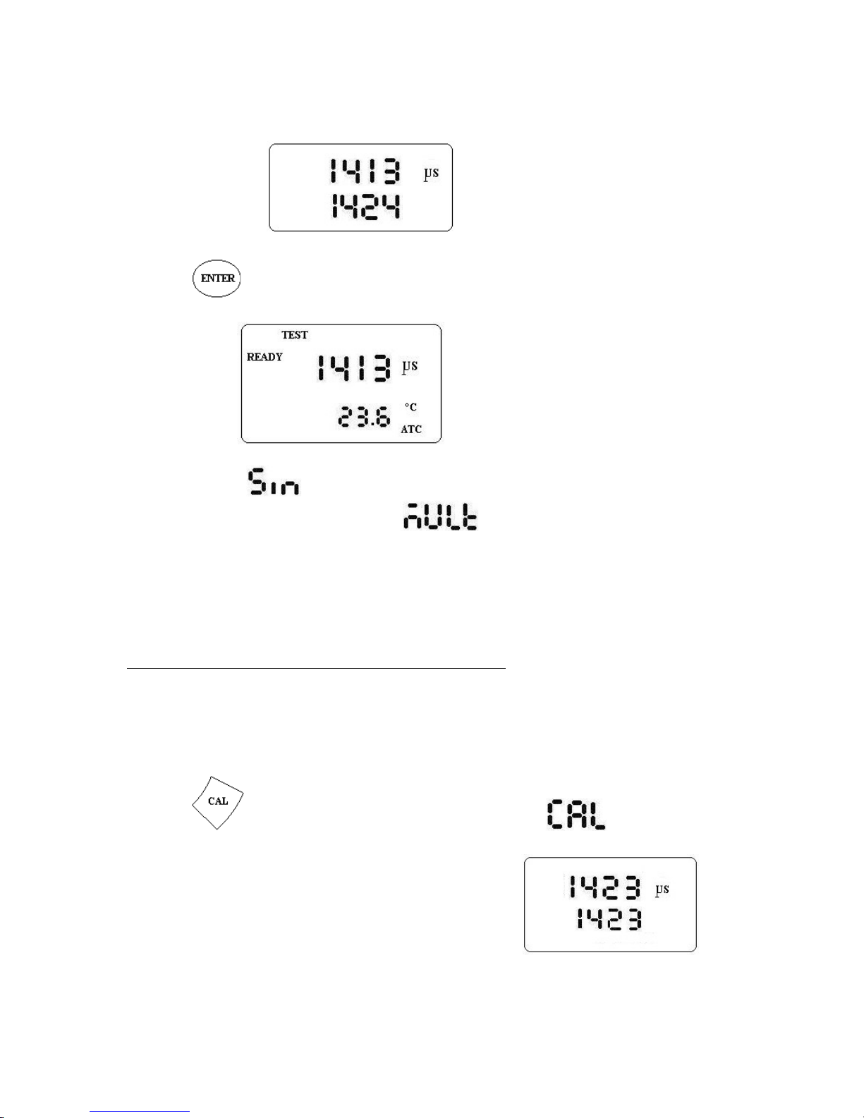
Press key. Meter calibrates to the new value and displays the results as below.
In SINGLE( ) mode calibration type, Calibration values of all the ranges
will be Changed, while in MULTI( ) mode Calibration of only the
current range ( Range 200 – 2000uS/cm) will be changed.
4.4 TEMPERATURE CALIBRATION
To calibrate the temperature sensor, Keep the meter in Conductivity measurement mode.
Immerse the temperature probe in to a solution with known temperature.
Press the key. The meter displays
and subsequently starts displaying the conductivity value.
Page 24
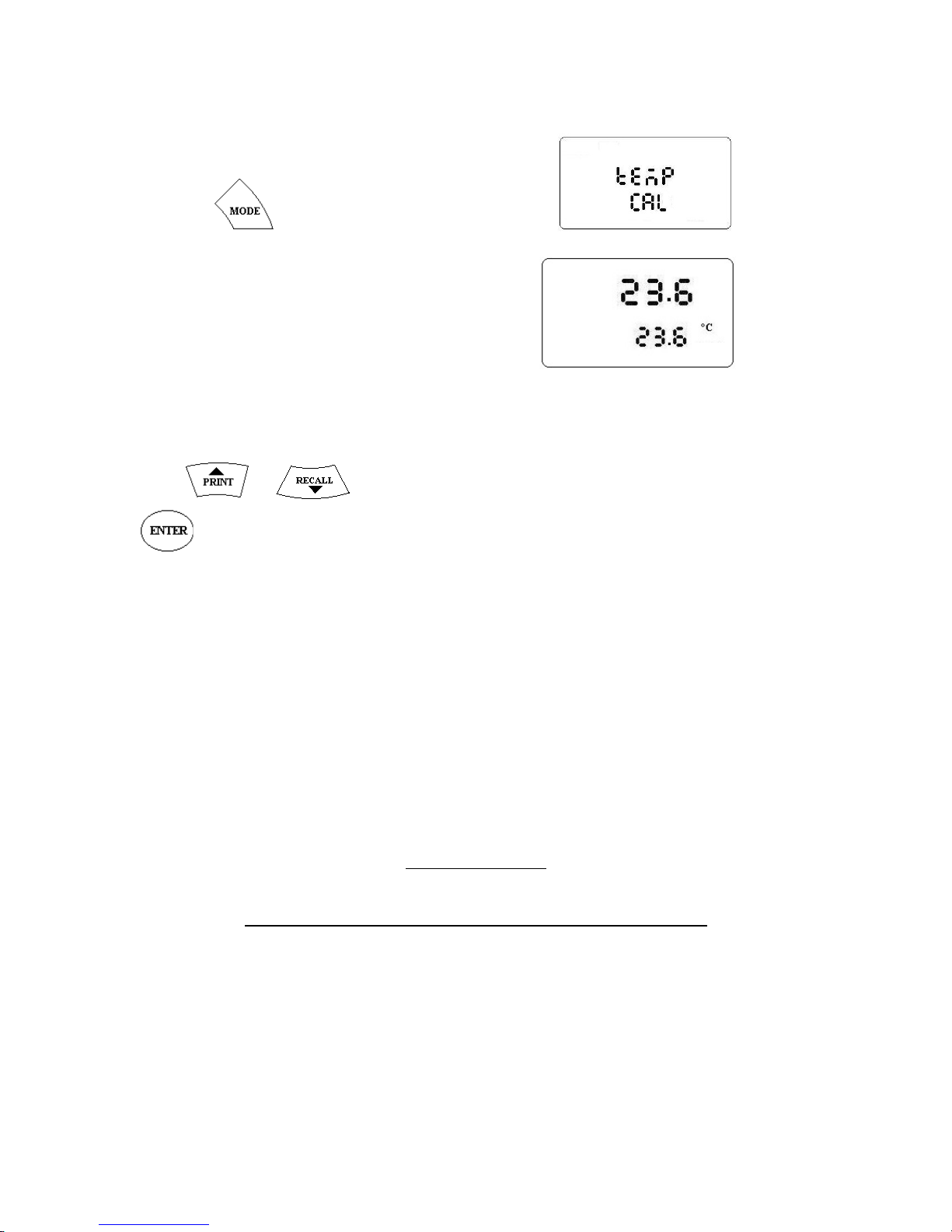
Keep the key pressed , till meter displays
Subsequently meter displays
Upper display shows the measured temperature and lower display shows the temperature
to be set.
Press or key to change the temperature to the known value and press
key to save the new temperature calibration. Meter will start displaying the new
value.
DISSOLVED OXYGEN MEASUREMENT
Switch on the meter and polarize the electrode for about 10 minutes.
Select the required unit ( Saturated %, ppm or mg/L)
Do electrode calibration if required.
CHAPTER 5
Page 25
To measure in static water, immerse DO electrode quickly in the water at an angle of 45
to 75o. Also, immerse the temperature sensor, if provided separately, in to the solution.
Wait for about 5 minutes and take the reading after it is stabilized.
To measure DO of flowing water, place DO electrode into the flowing water at an angle
of 45o to 75o. Also, direct the temperature sensor, if provided separately, in to the flowing
solution. Wait for about 5 minutes and take the reading after it is stabilized.
In both cases ensure that the salinity sensor is immersed fully into the solution under test.
During the DO measurement, please check the following.
1. Check if there are any air bubbles in the DO electrode solution. Fill the electrode
solution in the cap.
2. Keep the surface of electrode moist by keeping the sponge wet.
3. If there is large difference in the temperature of air and the solution, then immerse
the electrode in the sample solution for about 10 minutes, then insert the
electrode back into the calibration cover for another 5 to 10 minutes. Perform
electrode calibration before reading.
4. Each time the meter is switched on polarize the electrode for about 5 minutes.
5. DO reading are affected by Atmospheric pressure. Set the pressure using SETUP
functions ( Refer section 3.4.12 )
6. DO measurement is affected by the temperature of the solution under test.
Immerse the Temperature probe ( if provided separately) into the solution along
with DO electrode. In case of manual temperature compensation, Set the correct
temperature. ( Refer 3.4.3 for more details)
7. Meter automatically compensates DO readings with Salinity changes. Ensure to
completely immerse the salinity sensor in the DO electrode.
o
CONDUCTIVITY MEASUREMENT
CDO-01 measures conductivity of a solution in 5 measurement ranges, 0.00 –
20.00uS/cm, 20.0 – 200.0 uS/cm, 200 – 2000 uS/cm, 2.00 – 20.00 mS/cm, 20.0 – 200.0
mS/cm. Meter shifts the range automatically whenever measured value crosses the limits.
CHAPTER 5
Page 26
Meter is also provided with Automatic Temperature compensation(ATC) feature, where
in it corrects the variation of conductivity due to temperature changes. Meter is switched
to ATC mode automatically when a Pt-100 temperature probe is attached to it. It
measures the liquid temperature and applies necessary correction to the readings.
Temperature Coefficient:
Temperature compensation factor or Temperature Coefficient is factory set to a
temperature coefficient of 2.00 % per °C. This is good enough for majority of the
applications. However, it can be changed if required. Refer to section 3.4.9 for details.
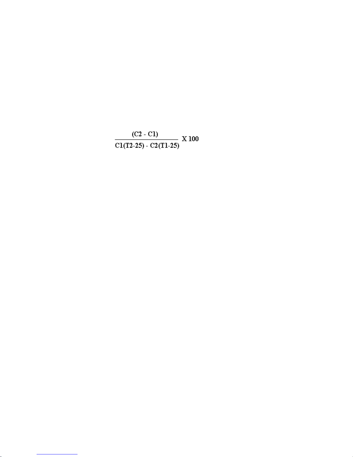
Temperature coefficient can also be calculated by using the following formula.
C1 = Conductivity of a solution at T1 oC
C2 = Conductivity of a solution at T2 oC
If the meter does not detect the temperature probe, meter switches to Manual temperature
compensation mode. There is a provision to manually enter the liquid temperature, if
required. Refer to section, 3.4.3 for changing the temperature.
Normalisation Temperature:
Using Automatic temperature compensation, Meter compensates for temperature
variations of a solution from the normalization temperature set. Default normalization
temperature is 25oC. However it can be changed from 15 to 30oC, if required. Refer to
section 3.4.11 for details.
Cell Constant:
Meter is supplied with an electrode of Cell constant 1.00. However, it can be changed to
suit a particular electrode. Refer to section 3.4.12 for more details.
Conductivity Electrode:
CDO-01 meter DO electrode is used for measuring salinity. DO electrode has inbuilt
sensor for measuring salainit. The sensor portion should be fully immersed in the liquid
under test.
To ensure accurate and reliable analytical measurements, a routine care and maintenance
regime should be adopted. In addition to giving the correct measurement result, correct
care and maintenance of electrodes will result in improved electrode performance and
prolonged working life. It also reduces the necessity for corrective intervention, thus
saving time and money.
During use the following points should be borne in mind:
Page 27

Electrodes should be calibrated using calibration buffers that bracket the expected
value of the sample. Calibration should be performed on a daily basis or more
frequently if sample throughput is high.
Stirring the sample during measurement is recommended but is not essential. But
same procedure must be followed for both calibration and measurement.
The electrode should be rinsed with a wash bottle of purified water between
measurements.
Keep the electrical parts of the electrode (the cable and connector) dry at all
times.
After a measurement is completed, remove the electrode from the sample.
While taking measurements,
Rinse the electrode with distilled water to remove any residue of the previous
measurement. Air it dry.
Rinse the electrode with the measuring sample.
Immerse the electrode in the measuring solution. Ensure that the steel ring of the
probe is immersed in the liquid. Stir the liquid gently for consistency.
Immerse the temperature probe also into the solution (If provided).
Wait for the Conductivity reading to stabilize.
Note down the Conductivity readings along with temperature.
Data logging is useful for studying the pattern of DO/Conducivity changes over time.
Meter stores the DO/Cond values along with temperature at a preset time interval. A
maximum of 500 readings can be stored and recalled.
CHAPTER 5
DATA LOGGING
Page 28
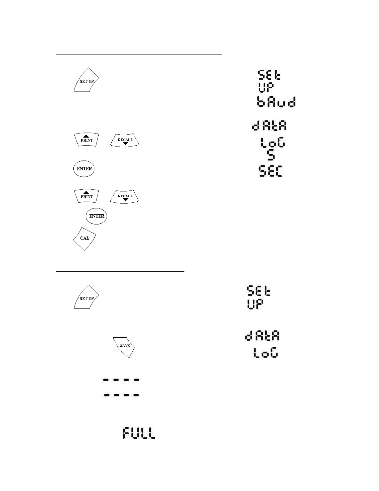
5.1 SET DATA LOGGING INTERVAL
Press key. The Meter displays
and subsequently displays
Press or key till it displays
Press key. Meter displays the set baud rate say 5 seconds
Press or key to change between 5S, 10S, 20S, 30S, 60S, 120S, 300S
and press key to save.
Press key to quit without saving
5.2 START DATA LOGGING.
Press key. The Meter displays
Immediately press key. Meter Displays
Meter starts storing the DO/CONd and temperature values at the set interval.
Meter displays every time it stores data.
A maximum of 500 readings can be stored. When the data reaches 500, meter displays
Page 29
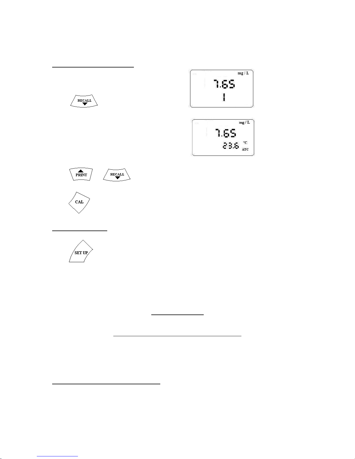
and it stops saving further data.
5.3 DATA RECALL.
Press key. Meter displays
and followed by
Press or key to scan through the saved data.
Press to quit.
TO PRINT DATA
Press key . A sample printout appears as below.
1. 7.85 mg/L 26.9oC
2. 7.93 mg/L 26,7oC
3. 8.25 mg/L 25.2oC
4. 8.35 mg/L 24.3oC
5. 6.35 mg/L 20.9oC
CHAPTER 6
SAVE AND RECALL OF DATA
A maximum of 100 numbers of measurement data including DO/Cond , Date, Time and
temperature can be stored and recalled.
6.1 TO CLEAR MEMORY:
Page 30
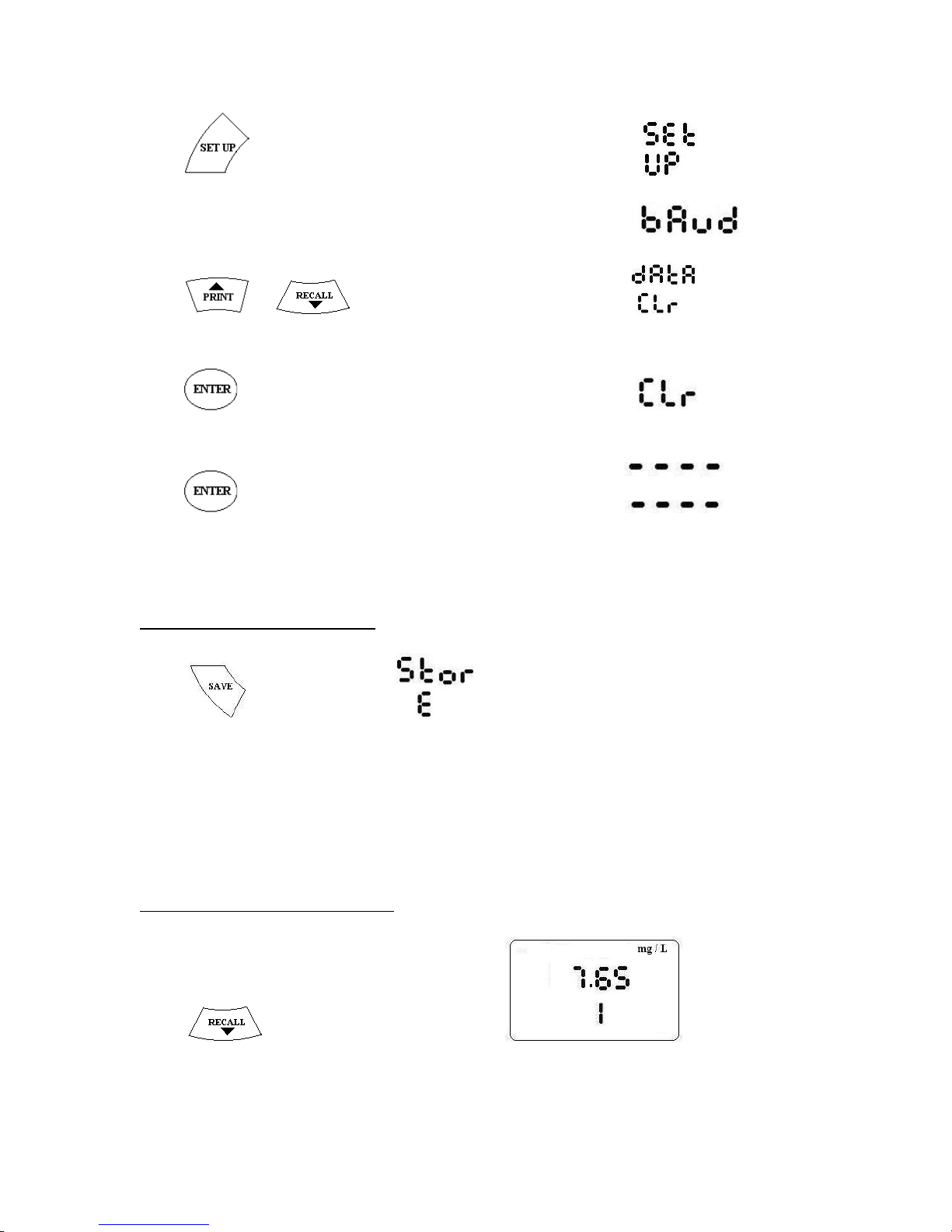
Press key. The Meter displays
and subsequently displays
Press or key till it displays
Press key. Meter displays
Press key again, Meter displays .
All the stored data will be cleared.
6.2 TO STORE DATA.
Press key. Meter displays . The measurement data along with date,
time and temperature will be stored in memory.
6.3 TO RECALL DATA:
Press key. Meter displays
Page 31
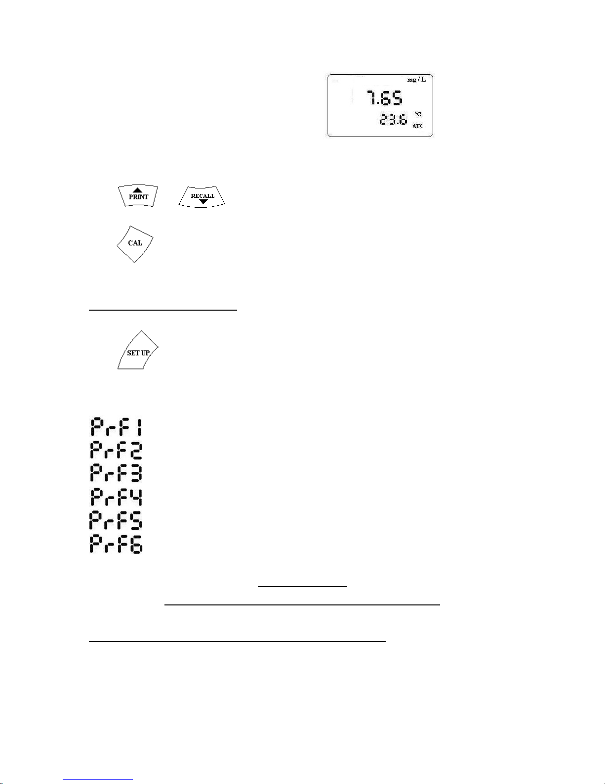
and followed by
Press or key to display saved data.
Press to quit.
6.4 TO PRINT DATA
Press key. Printout format can be selected by 3.4.6 and 3.4.7 in Chapter 3.
Selected Format Print output
- ONLY DO/Cond
- SERIAL NO, DO/Cond
- SERIAL NO, DATE,DO/ Cond
- SERIAL NO, TIME, DO/Cond
- SERIAL NO, DATE, TIME, DO/Cond
- SERIAL NO, DO/Cond, TEMPERATURE
CHAPTER 7
DATA PRINT AND RS232 INTERFACE
7.1 BIDIRECTIONAL RS232 INTERFACE
Bi-directional RS-232 interface is provided in the meter to communicate with
devices like computer, printer etc. The interface is provided through a nine pin D-type
connector provided at the rear side. Connections are as below.
Page 32
Pin 2 – RXD – Receive Data
Pin 3 - TXD – Transmit Data
Pin 7 – Ground.
The Serial data transmitted and received are in standard ASCII
mode ( +/- 12V) - ASYNCHRONOUS , 8 BITS, NO PARITY, 1 STOP BIT.
Baud rate: Selectable from 1200, 2400 ,4800 and 9600.
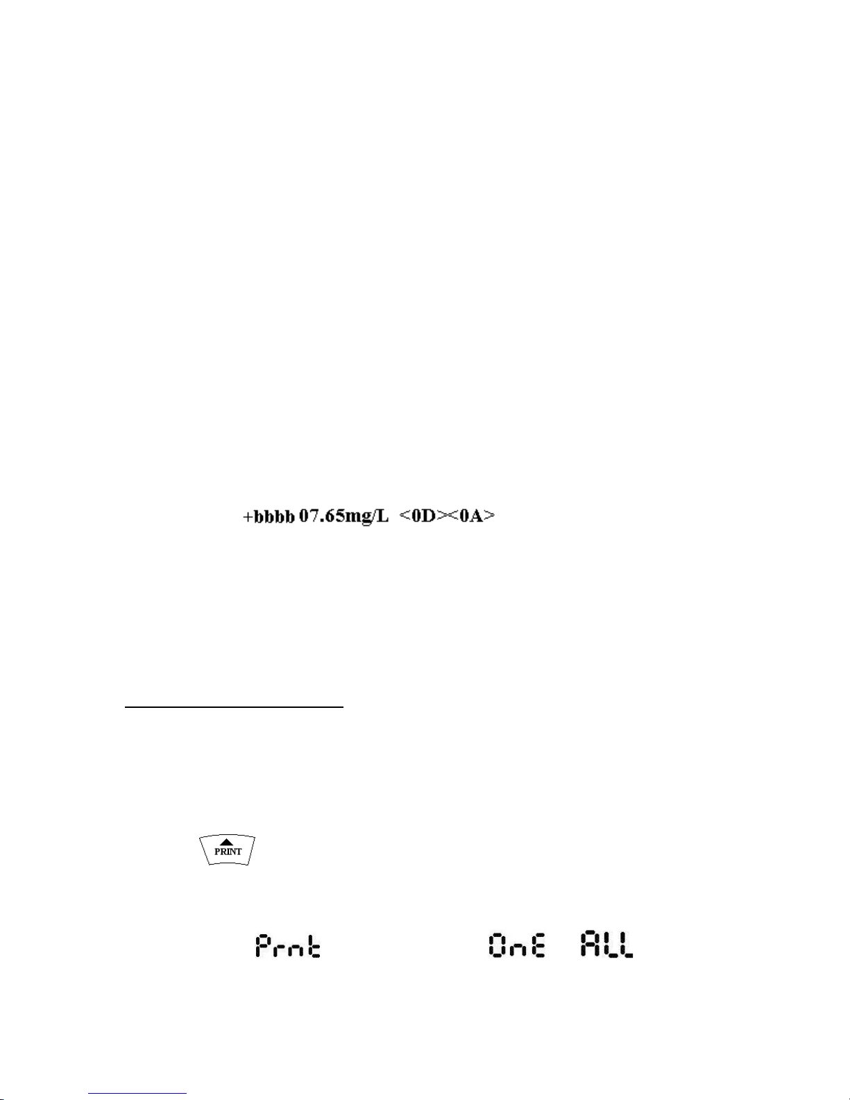
The data format is
<+/->PPPPPP.PPb <bUU> <CR><LF> ( 15 characters)
where PPPPPP.PP - DO or Cond value
b – blank space - 20 hex
CR- Carriage Return – 0D hex
LF – Line feed - 0A hex
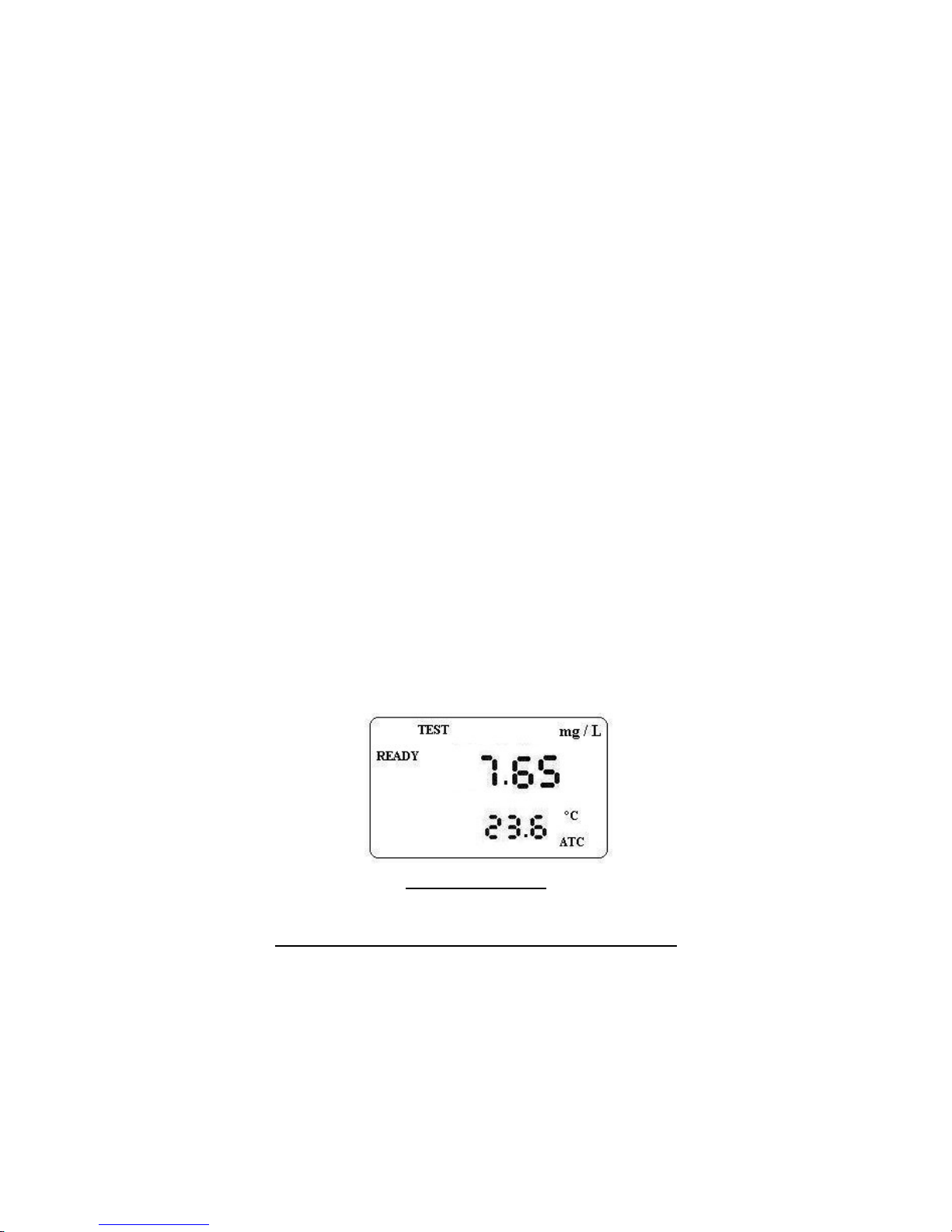
for example, a DO value of 7.65 mg/L will be sent as
Meter could be controlled by an external device like computer with the
following commands.
P# - Number of times, a stable DO/conductivity data is to be transmitted through
the serial port.
# can be any number from 1-9.
7.2 PRINT OPTIONS.
Meter can be attached to a serial printer for your printing needs. Print out can be
programmed to suit most of the printing requirements. See sections 3.4.2, 3.4.4, 3.4.5,
3.4.6 and 3.4.7 for setting parameters required for printing.
Press key to print data through the serial port.
Printing option and patterns are controlled by 3 SETUP parameters. They are
a) : There are 2 options : and
Page 33
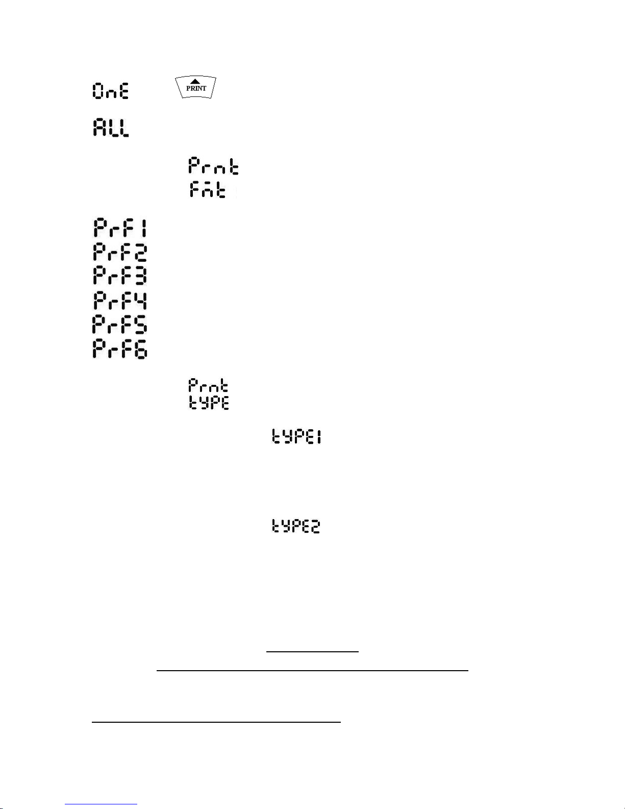
- Press key to print current DO/Cond through RS232 port.
- Continuous data transfer to computer/printer through RS232 port.
b) option:
- ONLY DO/Cond
- SERIAL NO, DO/Cond
- SERIAL NO, DATE,DO/ Cond
- SERIAL NO, TIME, DO/Cond
- SERIAL NO, DATE, TIME, DO/Cond
- SERIAL NO, DO/Cond, TEMPERATURE
c) Print type (Horizontal or Vertical)
i) – Horizontal
Details will be printed horizontally.
A Typical printout in the horizontal form appears as below.
1. 12.30.34 8.95 mg/L
2. 12.30.45 8.96 mg/L
ii) – Vertical
Details will be printed vertically in a slip form.
Sr.No. : 1
Time : 12.30.34
Value : 8.95 mg/L
CHAPTER 8
ELECTRODE PERFORMANCE AND GLP
8.1 GLP CALIBRATION REPORT
Page 34
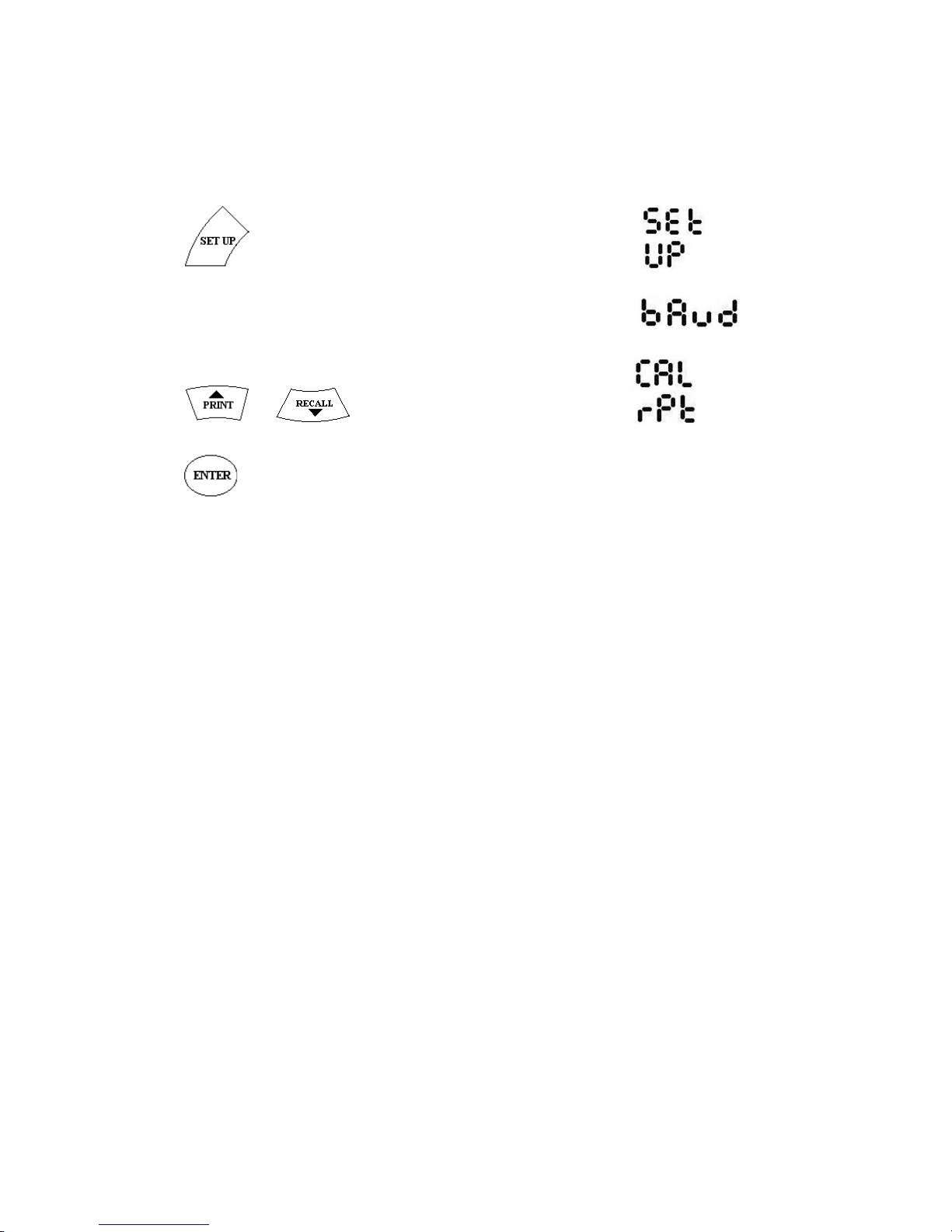
Report of the last calibration done, is available as per GLP requirements.
Press key. The Meter displays
and subsequently displays
Press or key till it displays
Press key. Meter Prints report of last calibration as below.
CONTECH
DISSOLVED OXYGEN METER
MODEL : CDO-01
MACHINE ID : ABCDEFGH
CAL. DATE :
CAL. TIME :
SPECIFICATIONS
1. Model : CDO-01
2. DO Range : 0 – 40 mg/L, 0 – 200%, Temp. 0 – 45oC
3. Conductivity Range : 0 to 20.00, 20-200.0, 200-2000 µS/cm; 0 to 20.00, 20.0 -200.0 mS/cm
4. Auto ranging : Yes.
5. Resolution : 0.05 % Full Scale
Page 35

6. Calibration Mode : Single or Multiple
7. Dissolved Oxygen : Zero and Saturated % calibration
8. Accuracy : ±1% Full Scale
9. Temperature compensation : Auto or Manual
10. Temperature range : 0 to 100oC in 0.1 deg increments
11. Cell Constant : 0.1 to 10.0 adjustable.
12. Temperature Coefficient : 0 to 10%/oC in 0.1% increments
13. Normalisation Temeperature : 15 oC to 30 oC
14. Memory : 100 nos.
15. Data logging : 500 nos.
16.Power : +9V/1A power adapter ( Input 100-260V AC, 50Hz)
17. Operating temperature : 15 to 45o c
18. Dimensions : 165(L) x 190(D) x 60(H)
19. Meter weight : 700g
20. Electrodes : 1. Glass Conductivity Electrode.
2. Temperature Probe.
Box Contents : Meter, DO electrode, Temperature Probe, 9V adapter, Instruction
manual, Electrode stand, Rod and holder.
 Loading...