

Page 1

FA-PC VPC Series
VPC-500P1
User’s Manual
CONTEC CO.,LTD.
Page 2

△△△△△
△△△△△
77000
77413
77129
77126
Name
Pcs
Pcs
Pcs
Pcs
PC 1 1 1 1
AC Power Cable(125VAC) *1
1 1 1
1
Product guide 1 1 1 1
Warranty Cert if icat e
1 1 1
1
Rubber Foot 4 4 4 4
Recove ry Med ia
None 1 1
1
Driver DVD 1 None
None
None
Screws
1set
None
None
None
SATA Cable 1 None
None
None
Product Guide
Warranty
Certificate
Check Your Packa g e
Thank you for purchasing the CONTEC product.
The product consists of the items listed below.
Check, with the following list, that your package is complete. If you discover damaged or missing items,
contact your retailer.
Product Configuration List
■
VPC-500P1-
Product Configuration Image
■
B
Reco very Media / Driver DVD Screws SATA Cable
*1 Do not use the bundled AC power cable with other products.
* See the Product Configu ration List to check if all the components are included for the specified number of units.
VPC-500P1 Series User’s Man u al
PC AC Pow er C a b le Product Guide Warranty Certificate Rubber Foot
i
Page 3

Copyright
(1) No part of this document may be copied or reproduced in any form by any means without prior
written consent of CONTEC CO., LTD.
(2) CONTEC CO., LTD. makes no commitment to update or keep current the information contained in
this document. The information in this document is subject to change without notice.
(3) All relevant issues have been considered in the preparation of this document. Should you notice an
omission or any questionable item in this document, please feel free to notify CONTEC CO., LTD.
(4) Regardless of the foregoing statement, CONTEC assumes no responsibility for any errors that may
appear in this document or for results obtained by the user as a result of using this product.
(5) Intel, Intel Atom, Intel Core and Celeron ar e regi st er ed trad ema rk s o f Int el C orp orat i on . MS,
Microsoft and Windows are trademarks of Microsoft Corporation. Other brand and product names
are trademarks of their respective holder.
VPC-500P1 Series User’s Man u al
ii
Page 4

Table of Contents
Check your package ............................................................................................................................. i
Table of Contents ............................................................................................................................... iii
1. INTRODUCTION 1
About the Product ............................................................................................................................... 1
◆Features .................................................................................................................................... 1
◆Supported OS ........................................................................................................................... 1
Customer Support................................................................................................................................ 2
Web Site ....................................................................................................................................... 2
How to Obtai n Servic e ........................................................................................................................ 2
Liability ............................................................................................................................................... 2
Safety Precautions ............................................................................................................................... 3
◆Safety Information.................................................................................................................... 3
◆Caution on the VPC-500P1 Series ........................................................................................... 3
2. SYSTEM REFERENCE 7
Specification ........................................................................................................................................ 7
Physical Dimensions ........................................................................................................................... 9
3. HARDWARE SETUP 11
Before Using the Product for the First Time ..................................................................................... 11
Hardwar e Setup ................................................................................................................................. 12
◆Drive Bay Desorption............................................................................................................. 12
◆Extension Board Installation .................................................................................................. 13
◆Installation Requirements ....................................................................................................... 13
4. EACH COMPONENT FUNCTION 15
Component Name .............................................................................................................................. 15
Component Function ......................................................................................................................... 17
◆LED : POWER LED, ACCESS LE D ..................................................................................... 17
◆Power Switch : POWER SW .................................................................................................. 17
◆Reset Switch : RESET SW ..................................................................................................... 17
◆Serial Port Interface : SERIA L ............................................................................................... 18
◆Analog RGB Port Inter f ace : ANALO G RGB ....................................................................... 19
◆HDMI Port Int erfa c e : HDMI ................................................................................................. 20
◆USB3.0 Port Interface : USB3.0 ............................................................................................ 21
◆USB2.0 Port Interface : USB2.0 ............................................................................................ 21
◆LAN Port Inte rface : LAN ..................................................................................................... 22
◆Line out Interface : LINE OUT .............................................................................................. 22
VPC-500P1 Series User’s Man u al
iii
Page 5

5. BIOS SETUP 23
Introduction ....................................................................................................................................... 23
◆Starting Setup ......................................................................................................................... 23
◆Using Setup ............................................................................................................................ 24
◆Getting Help ........................................................................................................................... 24
◆In Case of Problem ................................................................................................................. 24
◆A Final Note About Setup ...................................................................................................... 24
Main Menu ........................................................................................................................................ 25
◆Setup It em .............................................................................................................................. 25
Main .................................................................................................................................................. 26
Configuration .................................................................................................................................... 27
◆CPU Confi guration ................................................................................................................. 29
◆Chipset Configuration ............................................................................................................ 30
◆LAN Configuration ................................................................................................................ 31
◆Graphics Configuration .......................................................................................................... 32
◆PCI/PCIE Configuration ......................................................................................................... 34
◆PCI Expr ess Configuration ..................................................................................................... 35
◆SATA Configuration .............................................................................................................. 36
◆USB Configuration ................................................................................................................. 37
◆USB Confi guration ................................................................................................................. 38
◆Power Control Conf iguration ................................................................................................. 39
◆TPM Configuration ................................................................................................................ 41
◆Super IO Configuration .......................................................................................................... 42
◆H/W Monitor .......................................................................................................................... 43
◆Serial Port Console Redirection ............................................................................................. 44
Security ............................................................................................................................................. 45
Boot ................................................................................................................................................... 46
Save & Exit ....................................................................................................................................... 48
6. SOFTWARE UTILITY 49
Driver DVD ....................................................................................................................................... 49
Various dri vers .................................................................................................................................. 50
7. APPENDIX 51
Battery ............................................................................................................................................... 51
VPC-500P1 Series User’s Man u al
iv
Page 6

1. Introduction
◆
◆
1. Introduction
About the Prod uct
This product is a FA personal computer equipped with the Intel ® Atom processor E3845. It has
sufficient performance with low power consumption, as well as set up at a small area.
It has extension interfaces such as Analog RGB, HDMI, 1000BASE-T, USB 3.0, and serial. These Units
are ideal for a wide range of embedded applications, such as control devices and information terminals
based on general-purpose PC OSes.
I adopt Embedded-type chipset and CPU. The use of parts that can be stable supply, can be used with
confidence.
Features
Contributing to reduction of running cost and promotion of energy efficiency
■
It adopts the low-power platform with Intel
consumption while ensuring sufficient performance.
The compact size that can install at a small area
■
This product is a compact size PC of 112(W) x 263(D) x 264(H)mm th at can install at a small area.
The silent design that held the noise in check
■
It minimizes the noize while ensuring sufficient performance by abolishing a CPU fan.
Major types of peripherals are supported with rich interfaces including
■
It has a variety of extended interface such as PCI Express ×4 x 1sl ot, Analog RGB x 1, HDMI x 1,
1000BASE-T x 1, USB3.0 x 1, USB2.0 x 2, serial (RS-232C) x 1.
®
(TM)
Atom
Processor E3845 that realizes lower power
Safety design required for embedded applications
■
For Windows Embedded Standard installed model, it is possible to use the EWF*2 function of OS. It is
design ed f or s af ety requ i r ed for embedding purpose, for example, prohibiting unwanted writing to the
CF card with EWF function will relieve the concern about the writing limits to the CF card and prevent
an unintentional system alteration.
EWF (Enhanc ed Wr it e Filt er) is a function specific t o Windows Embedded Standard that pro tects the disk from being actually
*1
writt e n by
redirecting the wri ting to RAM
Supported OS
Windows Embedded Standard 7 SP1 32bit Japanese / English / Chinese / Korean
・
Windows 7 Professional SP1 32bit Japanese / English
・
Windows 7 Ultimate SP1 32bit Japanese / English / Chinese / Korean
・
VPC-500P1 Series User’s Man u al
1
Page 7

Customer Support
CONTEC provides the following support services for you to use CONTEC products more efficiently
and comfortably.
Web Site
Japanese http://www.contec.co.jp/
English http://www.contec.com/
Chinese http://www.contec.com.cn/
Latest product information
CONTEC provides up-to-date information on products.
CONTEC also provides product manuals and various technical documents in the PDF.
Free download
You can download updated driver software and differential files as well as sample programs available in
several languages.
Note! For product information
Contact your retailer if you have any technical question about a CONTEC product or need its price,
delivery time, or estimate information.
How to Obtain Service
For replacement or repair, return the device freight prepaid, with a copy of the original invoice. Please
obtain a Return Merchandise Authorization number (RMA) from the CONTEC group office where you
purchased before returning any product.
* No product will be accepted by CONTEC group without the RMA number.
Liability
The obligation of the warrantor is solely to repair or replace the product. In no event will the
warrantor be liable for any incidental or consequential damages due to such defect or consequences that
arise from inexperienced usage, misuse, or malfunction of this device.
VPC-500P1 Series User’s manual
2
Page 8

1. Introduction
◆
◆
DANGER
WARNING
CA
U
TI
ON
WARNING
Safety Precautions
Understand the following definitions and precautions to use the product safely
Safety Information
This document provides safety information using the following symbols to prevent accidents resulting
in injury or death and the destruction of equipment and resources. Understand the meanings of these
labels to operate the equipment safely.
DANGER indicates an imminently hazardous situation which, if not avoided, will
result in death or serious injury.
WARNING indicates a potentially hazardous situation which, if not avoided, could
result in death or serious injury.
CAUTION indicates a potentially hazardous situation which, if not avoided, may
result in minor or moderate injury or in property damage.
Caution on the VPC-500P1 Series
Handling Precautions
■
Always check that the power supply is turned off before connecting or disconnecting power cables.
・
Do not use this product in a location where flammable or corrosive gases are present. Doing so may
・
lead to explosions, fire, electric shock, or product failures.
Do not tou ch the gold-plated terminals (such as the edge connectors) of this product with your
・
hands. Doing so may lead to malfunctions or product failures. Be sure to turn the power off before
performing such an action.
When transporting or moving this product, be sure to use the original packaging in which it was
・
shipped from CONTEC or other equivalent packaging in order to prevent vibrations, impacts, and
static electricity.
Do not modify the pr oduct.
・
Always turn off the power before inserting or removing circuit boards or cables.
・
This product is not intended for use in aerospace, space, nuclear power, medical equipment, or other
・
applications that require a very high level of reliability. Do not use the product in such applications.
If using this product in applications where safety is critical such as in railways, automotiv e, or
・
disaster prevention or security systems, please contact your retailer.
Do not attempt to replace the battery as inappropriate battery replacement poses a risk of explosion.
・
For battery replacement, contact your retailer as it must be performed as a pro c es s of r ep ai r .
・
When disposing of a used battery, follow the disposal procedures stipulated under the relevant laws
・
and municipal ordinances. For details on replacing the battery, refer to the appendix.
VPC-500P1 Series User’s Man u al
3
Page 9

CAUTION
Do not use or store this product in a location exposed to high or low temperature that exceeds range
・
of specification or susceptible to rapid temperature changes.
Example: - Exposure to direct sun
- In the vicinity of a heat source
Do not use t his product in extremely humid or dusty locations. It is extremely dangerous to use this
・
product with its interior penetrated by water or any other fluid or conductive dust. If this product
must be used in such an environment, install it on a dust-proof control panel, for example.
Avoid using or storing this product in locations subject to shock or vibration that exceeds range of
・
specification.
Do not use t his product in the vicinity of devices that generate strong magnetic force or noise. Such
・
products will cause this product to malfunction.
To clean this product, wipe it gently with a soft cloth dampened with either water or mild detergent.
・
Do not use chemicals or a volatile solvent, such as benzene or thinner, to prevent pealing or
discoloration of the paint.
This product’s case may become hot. To avoid being burned, do not touch that section while this
・
product is in operation or immediately after turning off the power. Avoid installation in a location
where people may come into contact with that section.
CONTEC does not provide any guarantee for the integrity of data on SSD.
・
Always remove the power cable from the power outlet before mounting or removing an expansion
・
board and before connecting or disconnecting a connector.
Always remove the power cable from the power outlet before connecting or disconnecting a
・
connector.
To prevent corruption of files, always shutdown the OS before turning off this product.
・
CONTEC reserves the right to refuse to service a product modified by the user.
・
In the event of failure or abnormality (foul smells or excessive heat generation), unplug the power
・
cord immediately and contact your retailer.
Use an AC cable that matches the power supply voltage and outlet plug that you are using. (The
・
included cable is designed for use with a 125 VAC power supply.)
To connect with peripherals, use a grounded, shielded cable.
・
The SSD card connector doesn't support hot plug. The pulling out opening of the SSD card cannot
・
be done in the state of power supply ON. Please neither pulling out opening of SSD in the state of
power supply ON of this product nor come in contact with SSD. This product may malfunction or
cause a failure.
If you use any other SSD than our SSD, we can not guarantee this product’s specification. When
・
you newly select SSD for this product, you should read “Chapter 7” at first. If you select
unpreferable SSD, the system may work ou t of ord e r.
Component Li fe :
・
(1) Power ----- During continuous operation at 40℃, the ass umed life is about 4 year (vertical
installation). However, it may be shortened due to operation temperature (high
temperature).
VPC-500P1 Series User’s manual
4
Page 10

1. Introduction
(2) Battery --- The internal calendar clock and CMOS RAM are backed by a Lithium primary
battery. The backup time at a temperature of 25°C with the power disconnected is
less than 4 years.
* Replacement of expendables is handled as a repair (there will be a charge).
Do not use a UPS (Uninterruptible Power Supply) that generates square waves. Connecting the
・
product to this type of UPS may lead to product failure.
Replacing the battery with an inappropriate type of battery may lead to explosions. Dispose of used
・
batteries according to the instructions in the instruction manual.
When disposing of a used battery, follow the disposal procedures stipulated under the relevant laws
・
and municipal ordinances.
If using this product in an environment that is subject to noise, attach a ferrite core to each signal
・
cable (LAN, USB, serial, analog RGB, HDMI, and line output).
This product's specifications allow the device to be rebooted from the BIOS screen during startup.
・
This has no effect on operation after the OS boots.
VPC-500P1 Series User’s Man u al
5
Page 11

Port
Name
Maker
Pcs
Turn
Line ou t
GRFC-6
KGS
1
1
■
CAUTION
Ferrite core
Cable
【
FCC PART 15 Class A Noti ce
EMC Class A Notice
The ferrite core must be installed in the following audio cable (earphone, s p ea k er … ) so that this product
may suit the above-mentioned standard. For the type of ferrite core, refer to the following table
(Equivalent types are also available.)
Image diagram
TURN:1】
The object of the standard of this product become only a main body.
VPC-500P1 Series User’s manual
6
Page 12

2. System Reference
△△△△△
1,920×1,200 (1,6 77 colors, Reduce Blanking)
1,920×1,200 (1,6 77 colors, Reduce Blanking)
Baud rate : 50 - 115,200bps
The real-ti me clo ck is accur at e wit h in 3 minutes (at 25C) per month
Supports PC98/PC 99 ACPI Power management
VPC-500P1-77126B:Windows 7 Ultimate SP1 32b it Japanese / English / C hinese / Korean
2. System Reference
Specification
Table 2.1 Functio nal Speci f ic ati o n < 1 / 2 >
Model VPC-500P1-
CPU Inte l® At om™ Processor E384 5 1. 91GHz
BIOS AMI BIOS
Memory
Graphic *1 Inte l® HD Gr aphic s controller (built-in CPU)
System
resolution
Analog RGB 640×480, 800×600, 1,024×768, 1,152×864, 1,280×600, 1,280×720, 1,280×768, 1,280×800, 1,280×960,
4GB、204pin SO-DIMM so cket x1、PC3-10600 (DDR3L 1333) ECC
Analog RGB (15pin D-SUB connector) 1 port,
HDMI (19pin HDMI TYPE-A connector) 1 port
1,280×1,024, 1,360×768, 1,366×768, 1,400×1,050, 1,440×900, 1,600×900, 1,680×1,050, 1,920×1,080,
B
HDMI 640×480, 800×600, 1,024×768, 1,152×864, 1,280×600, 1,280×720, 1,280×768, 1,280×800, 1,280×960,
Storage
*2
Audio Realtek ALC892 controller
LAN Intel I210-AT controller
USB U SB 3.0 compliant (TYPE-A connector) 1 port (rear)
Serial I/F RS-232C/422/485 (9pin D-SUB connector(male)) 1 port
Hardware Mon ito r CPU temperature, powe r voltage
RTC/CMOS Litium backup batter y life : less than 4 years
Power Management Power management setup via BIOS, Power On by Ring / Wake On LAN,
Extended slot PCI Express ×4 1slot(2 lanes) Low Profile
Support OS
*2
*1 If the display cab le is connected after the PC turns on, BI OS is not displayed.
*2 The Functional Specification has differ in each purchase models.
1,280×1,024, 1,360×768, 1,366×768, 1,400×1,050, 1,440×900, 1,600×900, 1,680×1,050, 1,920×1,080,
VPC-500P1-77000B:None
VPC-500P1-77413B:SATAⅡ 2.5” SSD 32GB ×1
VPC-500P1-77129B / 77126B:SATAⅡ 2.5” HDD 500 GB ×1
HD Audio compliant, L ine out (3.5φ stereo min ij ack ) 1 port
1000BASE-T/100BASE-TX (RJ-45 connector) 1 port (Wake O n L A N support)
USB 2.0 compliant (TYPE-A connector) 2 port (front)
VPC-500P1-77000B:None
VPC-500P1-77413B:Windows Embedded Standard 7 SP 1 32bit Japanese / English / Ch ines e / Ko rea n
VPC-500P1-77129B:Windows 7 Professional SP1 32bit Japanese / English
VPC-500P1 Series User’s Man u al
7
Page 13
Model
VPC-500P1-△△△ △△B
Rated input voltage
100 - 240VAC 2A *3
Range of input
voltage
90 - 264VAC
Power consumption
(Max.)
160W
Current suppliable /
DC+3.3V:5.0A / -,
DC+5Vsb:1.5A / 0.24A
External device power
supply capacit y
USB3.0 I/F : +5V : 0. 9A (900mA x1)
USB2.0 I/F : +5V : 1A (500mA x2)
Physical d imensions
(mm)
116(W)×263(D)×264(H) (No protrusions)
Weight
About 3.4kg
CE class A
△△△△△
Operating temperature
0 - 40℃
Floating dust particles
Not to be excessive
Corrosive gases
None
(IEC61000-4-4 Le vel 3, EN61000-4-4 L e vel 3)
(JIS C60068-2-27 compliant, IEC60068-2-27 compliant)
Table 2.1 Functio nal Speci f ic ati o n < 2 / 2 >
Power supply
Current consumption
(Max)
Standard
*3 If a blackout happens at moments more tha n a rule, the PC may not retur n noe malc y.
The PC turn off. The PC turn on after hav i ng put the interval of around 30 seconds.
DC+5V :6.0A / 3. 69A,
DC+12V :10.0A / 0.59A,
RoHS
VCCI cla s s A
FCC c lass A
Table 2.2 Installation Environment Requirements
Model VPC-500P1-
B
-10 - 60℃
AC line / ±2kV, Signal line / ±1kV
Contact discharge / ±4kV (I EC61000-4-2 Lev el 2, EN61000-4-2 Level 2)
Atmospheric discharge / ±8kV (IEC61000-4-2 Level 3, EN61000-4-2 Level 3)
■VPC-500P1-77129B/77126B
10 - 50Hz/4.9m/s2 (0.5G)
25 min. each in x, y, and z directions
(JIS C60068-2-6準拠、IEC60068-2-6準拠)
■VPC-500P1-77000B/77413B
10 - 57Hz / semi-a mplitude : 0.075 mm, 57 - 150Hz / 9.8m/s2 (1 G)
40 min. each in x, y, and z directions
(JIS C60068-2-6 compl iant, I EC60068-2-6 compliant)
98m/s2 (10G) / 11ms / ha lf-sine s hock for 3 times in x, y, and z direct ions
Ambient
specifications
Storage te mp er ature
Humidity 10 - 90%RH (No condensation)
Line-noise
resistance
Vibration
resistance
Impact resistance
Grounding Class D grounding, SG-FG / continuity
Line noise
Static
electricity
resistance
Sweep
resistance
VPC-500P1 Series User’s manual
8
Page 14

2. System Reference
△△△△△
Physical Di mensions
VPC-500P1-
■
< Main unit dimensions >
△△△△△
B
Figure 2.1 VPC-500P1-
VPC-500P1 Series User’s Man u al
B Main unit dimensions
9
Page 15

VPC-500P1 Series User’s manual
10
Page 16

3. Hardware Setup
CAUTION
3. Hardware Setup
Before Using the Product for the First Ti me
Follow the next steps to set up this product :
STEP1 By referring to the information in this chapter, install, connect and set this product.
STEP2 Connect cables.
Connect the cable of necessary external devices, such as keyboard and a display, to this
product using appropriate cables.
STEP3 Turn on the power.
After verifying that you have correctly followed steps 1 and 2, turn on the power.
If you find any abnormality after turning on the power, turn it off and check to see if the
setup has been performed properly.
STEP4 Set up BIOS.
By referring to Chapter 5, set up BIOS. This setup requires a keyboard and a display.
* Before using this product, be sure to execute " Restore Defaults " to initialize the BIOS
settings to their default values.
(See Chapter 5, " Save &a Exit.")
Be sure to connect the keyboard and mouse to it before turning the power on for the first time.
・
Be sure to connect the display before turning the power on. Connecting the display after turning the
・
power on may prevent it from being displayed properly.
VPC-500P1 Series User’s Man u al
11
Page 17

◆
CAUTION
Hardware Set up
Before you start, be sure that the power is turned off.
・
Remove only those screws that are explained. Do not move any other screw.
・
Drive Bay Desorption
Figure 3.1 Drive Bay Desorption
Screw holes may be damaged if screws are tightened with a torque greater than the specified
torque.The specified tightening torque is 5 - 6kgf⋅cm.
VPC-500P1 Series User’s manual
12
Page 18

3. Hardware Setup
◆
◆
CAUTION
CAUTION
Remove the blank panel then install an extension board
Remove the screw
Pull up the extension board bracket
Extension Board Installation
Figure 3.2 Extension Board Installation
Screw holes may be damaged if screws are tightened with a torque greater than the specified
torque.The specified tightening torque is 5 - 6kgf⋅cm.
Installation Requirements
Be sure that the ambient temperature is within the range specified in the installation environment
requirement by making space between the product and device that generates heat or exhaust air.
Figure 3.3 Installation Image
Note that even though the ambient temperature is within the specified range, an operational
malfunction may occur if there is other device generating high heat; the radiation will influence the
product to increase its temperature.
VPC-500P1 Series User’s Man u al
13
Page 19

CAUTION
CAUTION
Horizonta l orientation
■
Figure 3.4 Horizontal orientation
Attach the stand to the base of the product in order to prevent the blocking of the slit on the base of
・
the product.
Adjust the air flow so as not to allow waste heat from the product to accumulate around the product.
・
Do not install this product in completely sealed spaces, except when it is possible to adjust the
・
internal temperature using an air conditioner or similar equipment. Temperature increase caused by
long-term usage may result in operational malfunction or other problems.
Vertical orientation
■
Figure 3.5 Vertical orientation
Attach the stand to the base of the product in order to prevent the blocking of the slit on the base of
・
the product.
Adjust the air flow so as not to allow waste heat from the product to accumulate around the product.
・
Do not install this product in completely sealed spaces, except when it is possible to adjust the
・
internal temperature using an air conditioner or similar equipment. Temperature increase caused by
long-term usage may result in operational malfunction or other problems.
VPC-500P1 Series User’s manual
14
Page 20

4. Each Component Function
△△△△△
△△△△△
4. Each Compone n t Fu nc t io n
Component Name
VPC-500P1-
■
< Front Vie w >
Figure 4.1 VPC-500P1-
< Rear View >
△△△△△
B
B Component Name < 1 / 2 >
Figure 4.1 VPC-500P1-
VPC-500P1 Series User’s Man u al
B Component Na me < 2 / 2 >
15
Page 21

Name
Function
POWER-SW
Power switch
POWER LED
Power ON display LED
ACCESS LED
SATA device access display LED
RESET-SW
Reset switch
USB2.0
USB2.0 (TYPE-A connector) 2 port
SERIAL
RS-232C/422/485 (9pin D-SUB connector ( male)) 1 port
ANALOG RGB
Analog RGB (15pin D-SUB connector) 1 port
HDMI
HDMI (19pin HDMI TYPE-A connector) 1 port
USB3.0
USB3.0 (TYPE-A connector) 1 port
LAN
1000BASE-T/100BASE-TX (RJ-45 connector) 1 port
LINE OUT
Line out (3.5φ stereo minijack) 1 port
AC INLET
AC100-240V Power input connector
Table 4.1 Component Function
VPC-500P1 Series User’s manual
16
Page 22

4. Each Component Function
◆
LED name
Status
Display contents
POWER LED
OFF
Indicate s that this product is switched off.
ON (Blue)
Indicate s that this product is switched on.
ACCESS LED
ON (Orange)
Indicate s that the SATA device i s being accessed.
◆
◆
Component Function
LED : POWER LED, ACCESS LED
There are 2 LED in f r ont of this product
Table 4.2 Display Contents of LED
Power Switch : POWER SW
POWER SW is provided.
Reset Switch : RESET SW
RESET SW is provided.
VPC-500P1 Series User’s Man u al
17
Page 23

◆
Connecto r type
9pin D-SUB connector (male)
RS-232C
RS-422
RS-485
Pin No.
Signal name
Pin No.
Signal name
Pin No.
Signal name
1
DCD 1 TX- 1 DATA-
2
RD 2 TX+ 2 DATA+
3
TD 3 RX+ 3 N.C.
4
DTR 4 RX- 4 N.C.
5
GND 5 GND 5 GND
6
DSR 6 N.C. 6 N.C.
7
RTS 7 N.C. 7 N.C.
8
CTS 8 N.C. 8 N.C.
9
RI 9 N.C. 9 N.C.
1 5
96
No.4-40UNC
Inch screw threads
Serial Port Interface : SERIAL
The product has 2 channels of RS-232C compliant serial ports supporting up to a baud rate of
115,200bps with a 16-byte transmission-dedicated data buffer and a 16-byte recept i on -dedicated data
buffer.
Table 4.3 SERIAL I/O Addresses and Interrupts
SERIAL I/O Address Interrupt
- 3F8h *1
*1 Leave these settings as configured.
IRQ 4 *1
Table 4.4 Serial Port Connector
VPC-500P1 Series User’s manual
18
Page 24

4. Each Component Function
◆
Connector type
15pin D-SUB connector (female)
Pin No.
Signal name
Pin No.
Signal name
1
RED 9 VCC
2
GREEN
10
GND
3
BLUE
11
N.C.
4
N.C.
12
DDCDATA
5
GND
13
HSYNC
6
GND
14
VSYNC
7
GND
15
DDCCLK
8
GND
5
1
11
15
10 6
No.4-40UNC
Inch screw
threads
CAUTION
Analog RGB Port In t erf ace : ANALOG RGB
The product is equipped with 1 port for analog RGB interface.
Table 4.5 Analog RGB port connector
If the OS is booted without connecting the display cable, and then the display is connected after the
・
OS boots, the display may not be shown pr operly.
When the analog display is used, Windows MS-DOS may not be properly displayed in full-screen
・
mode. This is because the frequency and resolution of Windows and MS-DOS (full-screen d i splay)
are the same due to the screen settings while the display parameters are different. For display, as
only one parameter can be stored for one frequency or resolution, only either of Windows or MSDOS screen can be displayed properly. In this case, change the resolution or display frequency of
Windows so that it is not the same as for the MS-DOS display.
When using a digital display, an analog display may be detected even though no analog display is
・
connected. This will not affect how the digital display appears. However, change the multi-display
settings as necessary.
To change the settings from digital output to analog output, change the settings from the standard
・
Windows properties screen.
VPC-500P1 Series User’s Man u al
19
Page 25

◆
Connector type
19pin HDMI connector (male)
Pin No.
Signal name
Pin No.
Signal name
1
HDMI D0+
2
GND
3
HDMI D0-
4
HDMI D1+
5
GND
6
HDMI D1-
7
HDMI D2+
8
GND
9
HDMI D2-
10
HDMI D3+
11
GND
12
HDMI D3-
13
N.C.
14
N.C.
15
HDMI DDC CLK
16
HDMI DDC DATA
17
GND
18
VCC
19
HDMI HPD IN
11 9 7 5 3 113151719
10 8
6
4 2
12141618
19 1
2
1
8
CAUTION
HDMI Port Interface : HDMI
The product is equipped with 1 port for HDMI interface.
Table 4.6 HDMI port connector
If the OS is booted without connecting the display cable, and then the display is connected after the
・
OS boots, the display may not be shown pr operly.
When using a digital display, an analog display may be detected even though no analog display is
・
connected. This will not affect how the digital display appears. However, change the multi-display
settings as necessary.
To change the settings from digital output to analog output, change the settings from the standard
・
Windows properties screen.
20
VPC-500P1 Series User’s manual
Page 26

4. Each Component Function
◆
Connector type
TYPE-A connector (female)
Pin No.
Signal name
1
USB_VCC
2
DATA-
3
DATA+
4
USB_GND
5
SSRX-
6
SSRX+
7
USB_GND
8
SSTX-
9
SSTX+
◆
Connector type
TYPE-A connector (female)
Pin No.
Signal name
1
USB_VCC
2
DATA-
3
DATA+
4
USB_GND
1 4 9 5 1
4
USB3.0 Port Interface : USB3.0
The product is equipped with 1 port for USB3.0 interface.
Table 4.7 USB3.0 port connector
USB2.0 Port Interface : USB2.0
The product is equipped with 2 port for USB2.0 interface.
Table 4.8 USB2.0 port connector
VPC-500P1 Series User’s Man u al
21
Page 27

◆
Connector type
RJ-45
100Base-TX
1000Base-T
Signal name
Signal name
1
TX-
TRD+ (0)
2
TX+
TRD- (0)
3
RX-
TRD+ (1)
4
N.C.
TRD+ (2)
5
N.C.
TRD- (2)
6
RX-
TRD- (1)
7
N.C.
TRD+ (3)
8
N.C.
TRD- (3)
◆
8
1
LAN Port Interface : LAN
The product is equipped with 1 port for LAN interface of gigabit ethernet.
Network type : 1000BASE-T/100BASE-TX
・
Transmission speed
・
Max. network path length : 100m/ segment
・
Controller : Intel I210AT controller
・
Use a cate go ry 5e or more ca ble for 1000 Mb ps ope ra tio n.
*2
Table 4.9 LAN port connect or
Pin No.
: 1000M/100M
*2
LINK/ACT 100/10 00M
LEDs for di s play of network statuses :
LINK/ACT LED : Nomal connection -> Green ON
: Data transmission and receive -> Green Blinking
100/1000M LED : 100M operation -> Green ON
: 1000M operation -> Orange ON
Line out Interface : LINE OUT
The product is equipped with 1 port for line out. You can plug a headphone or amplifier-integrated
speakers into this connector.
VPC-500P1 Series User’s manual
22
Page 28

5. BIOS Setup
◆
5.
BIOS Setup
Introduction
This chapter discusses American Megatrends’s (AMI) Setup program built into the FLASH ROM BIOS.
The Setup program allows users to modify the basic system configuration. This special information is
then stored in FLASH ROM so that it retains the Setup information when the power is turned off.
The rest of this chapter is intended to guide you through the process of configuring your system using
Setup.
Starting Setup
The AMI BIOS is immediately activated when you first power on the computer. The BIOS reads the
system information contained in the FLASH ROM and begins the process of checking out the system
and configuring it. When it finishes, the BIOS will seek an operating system on one of the disks and
then launch and turn control over to the operating system.
While the BIOS is in control, the Setup program can be activated in one of two ways:
By pressing <Del> or <ESC> immediately after switchi ng the system on, or
・
By pressing the <Del> or <ESC> key when the following message appears briefly at the bottom
・
of the screen during the POST (Power On Self-Test).
Press <DEL> or <ESC> t o e nte r set up.
If the m essage disapp ears be fore you respond and you still wish to enter Setup, restart the system to try
again by turning it OFF then ON on the system case. You may also restart by simultaneously pressing
<Ctrl>, <Alt>, and <Delete> keys.
VPC-500P1 Series User’s Man u al
23
Page 29

◆
Left Arrow
Move to the item on the left (menu bar)
Right Arrow
Move to the item on the right (menu bar)
Increase the numeric value or make changes
Decrease the numeric value or make changes
F3 Key
Load the optimal defaults fro m the BIOS default table.
F4 Key
Save all the changed setting s to the FLASH ROM and exit
◆
◆
◆
Using Setup
In general, you use the arrow keys to highlight items, press <Enter> to select, use the PageUp and
PageDown keys to change entries, press <F1> for help and press <Esc> to quit. The following table
provides more detail about how to navigate in the Setup program using the keyboard.
Table 5.1 Using Setup
Key Function
Up Arrow Move to the previous item
Down Arrow Move to the next item
ESC
Move Enter Move to the item you desired
+ Key
- Key
F1 Key General help on Setup navigation keys
F2 Key Load the previous settings.
Getting Help
Main Menu : Quit without saving changes
Submenus : Exit Current page to the next higher level menu
Press F1 to pop up a small help window that describes the appropriate keys to use and the possible
selections for the highlighted item. To exit the Help Window press <Esc> or the F1 key again.
In Case of Problem
If you cannot boot the computer after using Setup to change and save system settings, the computer will
have to be repa ired. It is safest not to change system settings you do not fully understand. Therefore, it
is strongly recommended that you do not change any of the default settings for the chipset. These
defaults have been selected with sufficient consideration by the AMI and system manufacturers to
ensure maximum performance and reliability. Even changing the chipset settings slightly can result in
an unavoidable need for repairs.
A Final Note About Setup
The information in this chapter is subject to change without notice.
VPC-500P1 Series User’s manual
24
Page 30

5. BIOS Setup
Aptio Setup Utility - Copyright (C) 20xx American Megatrends, Inc.
Main
Configuration
Security
Boot
Save & Exit
Project Name SMB-IE3845-LVA
BIOS Version & Build Date R1.00.E3 (12/10/2015 14:10:00)
EC Version & Build Date R04.E03
Processor information
Brand String Intel(R) Atom(TM) CPU E3845 @ 1.91GHz
Memory Information
Total Memory 4096 MB (LPDDR3)
TXE Information
TXE FW Version 01.01.00.1089
System Date [Week Day MM/DD/YYYY]
System Time [HH:MM:SS]
Access Leve l Administrator
Version x.xx.xxxx. Copyright (C) 20xx Am erican Megatrends, Inc.
◆
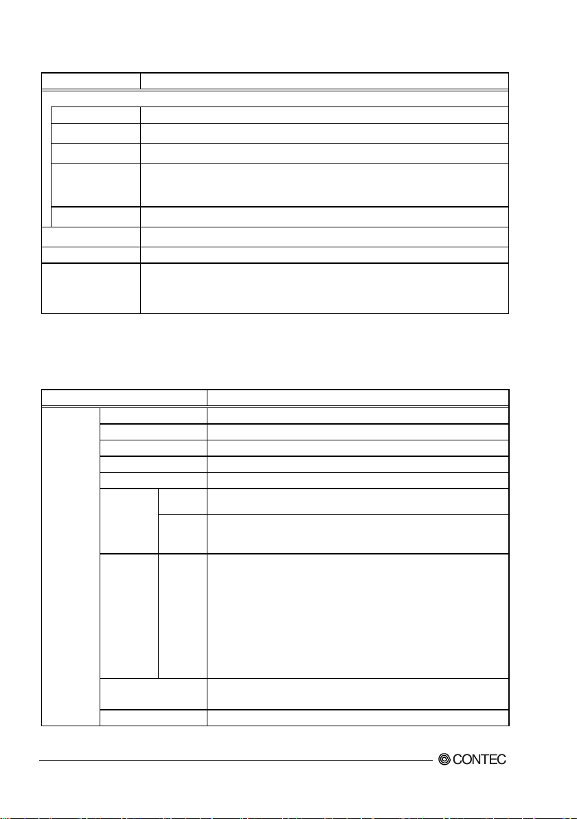
Main Menu
When the setup program (Aptio Startup Utility) is started, the main menu will be displayed. Navigate
through the various tabs by pressing the right and left arrow key.
Figure 5.1 Main Menu (Actual Display May Vary.)
Setup Item
The selectable tabs are as follows.
Main
■
View the basic system structure, and configure the date and time settings.
Configuration
■
Specify the detailed system functions.
Security
■
Set the password to be used to protect the security of the system.
Boot
■
Configure the settings related to how the system will boot.
Save & Exit
■
Load/save setup items and exit the setup menu.
VPC-500P1 Series User’s Man u al
25
Page 31

Aptio Setup Utility - Copyright (C) 20xx American Megatrends, Inc.
Main
Configuration
Security
Boot
Save & Exit
Project Name SMB-IE3845-LVA
BIOS Version & Build Date R1.00.E3 (12/10/2015 14:10:00)
EC Version & Build Date R04.E03
Processor information
Brand String Intel(R) Atom(TM) CPU E3845 @ 1.91GHz
Memory Information
Total Memory 4096 MB (LPDDR3)
TXE Information
TXE FW Version 01.01.00.1089
System Date [Week Day MM/DD/YYYY]
System Time [HH:MM:SS]
Access Leve l Administrator
Version x.xx.xxxx. Copyright (C) 20xx Am erican Megatrends, Inc.
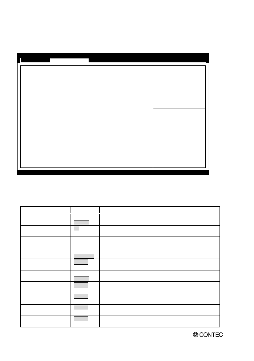
date and time.
Set the system date. Note that th e ‘Day’
date
System Time
Hour : Minute : Second
Set the system time
Main
View the basic system structure.
Figure 5.2 Main (Actual Display May Vary.)
Table 5.2 Main
Item Option Description
BIOS Version & Build Date R1.00.E3 (02/13/2015 10:54:43)
Displays the BIOS version and creation
System Date Week Day Month / Day / Year
VPC-500P1 Series User’s manual
26
automatically changes when you set the
Page 32

5. BIOS Setup
Aptio Setup Utility - Copyright (C) 20xx American Megatrends, Inc.
Main
Configuration
Security
Boot
Save & Exit
▶ CPU Configuration
▶ Chipset Configuration
▶ LAN Configuration
▶ Graphics Configuration
▶ PCI/PCIE Configuration
▶ SATA Configuration
▶ USB Configuration
▶ Power Control Configuration
▶ TPM Configuration
▶ Super IO Configuration
▶ H/W Monitor
▶ Serial Port Console Redirection
→←:Select Screen
↑↓:Select Item
Enter:Select
+/-:Change Opt.
F1:General Help
F2:Previous Values
F3:Optimized Defaults
F4:Save & Exit
ESC:Exit
Version x.xx.xxxx. Copyright (C) 20
xx American Megatrends, Inc.
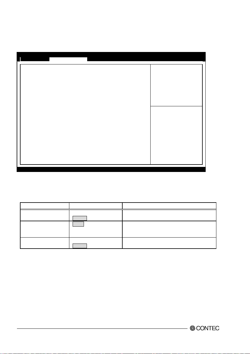
Configuration
Specify the detailed system functions.
Figure 5.3 Configuration
CPU Configuration
■
Configure the CPU settings.
Chipset Configuration
■
Configure the Chipset settings.
LAN Configuration
■
Configure the LAN controller settings.
Graphics Configuration
■
Configure the Graphics controller settings.
PCI/PCIE Configuration
■
Configure the PCI bus and the PCI Express bus settings.
SATA Configuration
■
Configure the SATA controller settings.
USB Configuration
■
Configure the USB controller settings.
Power Control Configuration
■
Configure the Power control settings.
TPM Configuration
■
Configure the TPM settings.
Super IO Configuration
■
Configure the Super IO settings.
VPC-500P1 Series User’s Man u al
27
Page 33

H/W Monitor
■
View such hardware monitor information as the CPU temperature.
Serial Port Console Configuration
■
Configure the Serial port console settings.
VPC-500P1 Series User’s manual
28
Page 34

5. BIOS Setup
◆
Aptio Setup Utility - Copyright (C) 20
xx American Megatrends, Inc.
Configuration
CPU Configuration
CPU Signature 30679
Microcode Patch
901
Max CPU Speed 1910MHz
Min CPU Speed 500MHz
Processor Cores 4
Intel HT T ec hn ology Not Supported
Intel VT-x Technology Supported
64-bit Supported
L1 Data Cache 24 KB x 4
L1 Code Cache 32 KB x 4
L2 Cache 1024 KB x 2
Active Processor Cores
[All]
Intel Virtualization Technology [Enabled]
EIST [Enabled]
CPU C6 report [Disabled]
→←:Select Screen
↑↓:Select Item
Enter:Select
+/-:Change Opt.
F1:General Help
F2:Previous Values
F3:Optimized Defaults
F4:Save & Exit
ESC:Exit
Version x.xx.xxxx. Copyright (C) 20xx Am erican Megatrends, Inc.
Item
Option
Description
All
1
Intel Virtualization
Technology
Disabled
Enabled
Enabled
Disabled
Enabled
CPU Configuration
Configure the CPU settings.
Figure 5.4 CPU Configuration
Table 5.3 CPU Configurati on
Active Processor Cores
EIST
CPU C6 report
VPC-500P1 Series User’s Man u al
Do not change this setting.
Do not change this setting.
Disabled
Do not change this setting.
Do not change this setting.
29
Page 35

◆
Aptio Setup Utility - Copyright (C) 20xx American Megatrends, Inc.
Configuration
Chipset Configuration
High Precision Timer [Enabled]
Audio Controller [Enabled]
Memory Information
Total Memory 4096 MB (LPDDR3)
→←:Select Screen
↑↓:Select Item
Enter:Select
+/-:Change Opt.
F1:General Help
F2:Previous Values
F3:Optimized Defaults
F4:Save & Exit
ESC:Exit
Version x.xx.xxxx. Copyright (C) 20xx Am erican Megatrends, Inc.
Item
Option
Description
Enabled
Disabled
Disabled
Enabled
Chipset Configuration
Configure the Chipset settings.
Figure 5.5 Chipset Configuration
Table 5.4 Chipset Configuration
High Precision Timer
Audio Controller
Configure the high-precision event ti mer settings.
Configure the audio controller settings.
30
VPC-500P1 Series User’s manual
Page 36

5. BIOS Setup
◆
Aptio Setup Utility - Copyright (C) 20
xx American Megatrends, Inc.
Configuration
LAN Configuration
Intel Ethernet Controller WGI210AT
LAN MAC Address
XX-XX-XX
-XX-XX-XX
Launch Legacy PXE Rom [Disable]
Wake On Lan Controller [Enabled]
→←:Select Screen
↑↓:Select Item
Enter:Select
+/-:Change Opt.
F1:General Help
F2:Previous Values
F3:Optimized Defaults
F4:Save & Exit
ESC:Exit
Version x.xx.xxxx. Copyright (C) 20xx Am erican Megatrends, Inc.
Item
Option
Description
Disable
Auto
Enabled
Disabled
LAN Configuration
Configure the LAN controller settings.
Figure 5.6 LAN Configuration
Table 5.5 LAN Configuration
Launch Legacy PXE
Rom
Wake On Lan Controller
VPC-500P1 Series User’s Man u al
Enable
Do not change this setting.
Configure the wake on lan settings.
31
Page 37

◆
Aptio Setup Utility - Copyright (C) 20xx
American Megatrends, Inc.
Configuration
Graphics Configuration
GOP Configuration
GOP Driver [Enabled]
Intel IGD Configuration
Integrated Graphics Device [Enabled]
IGD Turbo Enable [Enabled]
Primary Display [IGD]
DVMT Pre-Allocated [64M]
DVMT Total Gfx Mem [256MB]
IGD Output Display control - GOP
Force Lid Status [On]
BIA [Auto]
ALS Support [Disabled]
IGD Flat Panel [Auto]
Pannel Scaling [Auto]
IGD Output Display control - CSM
Primary IGFX Boot Display [CRT]
Secondary IGFX Boot Display [HDMI]
→←:Select Screen
↑↓:Select Item
Enter:Select
+/-:Change Opt.
F1:General Help
F2:Previous Values
F3:Optimized Defaults
F4:Save & Exit
ESC:Exit
Version x.xx.xxxx. Copyright (C) 20xx American Megatrends, Inc.
Item
Option
Description
Enabled
Disabled
Integrated Graphics
Device
Enabled
Disabled
Enabled
Disabled
Auto
SG
64M
352M
Graphics Configuration
Configure the Graphics controller settings.
Figure 5.7 Graphics Configuration
Table 5.6 Graphics Configuration
GOP Driver
IGD Turbo Enable
Primary Display
DVMT Pre-Allocated
VPC-500P1 Series User’s manual
32
IGD
PCI
96M
128M
160M
192M
224M
256M
288M
320M
Do not change this setting.
Do not change this setting.
Do not change this setting.
Do not change this setting.
Do not change this setting.
Page 38

5. BIOS Setup
Item
Option
Description
512M
128M
Max
Configure the settings for the port that will be output as the main
Can not change this setting.
Can not change this setting.
384M
416M
448M
480M
DVMT Total Gfx Mem
Primary IGFX Boot
Display
Secondary IGFX Boot
Display
256M
CRT
HDMI
Do not change this setting.
display at start-up.
If the main and auxiliary is connected, only the main display is
displayed during BIOS display and OS recovery.
Configure the settings for the port that will be output as the
auxiliary display at start-up.
VPC-500P1 Series User’s Man u al
33
Page 39

◆
Aptio Setup Utility - Copyright (C) 20xx American Megatrends, Inc.
Main
Configuration
Security
Boot
Save & Exit
PCI/PCIE Configuration
▶ PCI Express Configuration
→←:Select Screen
↑↓:Select Item
Enter:Select
+/-:Change Opt.
F1:General Help
F2:Previous Values
F3:Optimized Defaults
F4:Save & Exit
ESC:Exit
Version x.xx.xxxx. Copyright (C) 20xx Am erican Megatrends, Inc.
Item
Option
Description
PCI Express
Configuration
Refer to
Table 5.8
PCI/PCIE Configu ra tion
Configure the PCI bus and PCI Express bus settings.
Figure 5.8 PCI/PCIE Configuration
Table 5.7 PCI/PCIE Configuration
VPC-500P1 Series User’s manual
34
-
Page 40

5. BIOS Setup
◆
Aptio Setup Utility - Copyright (C) 20
xx American Megatrends, Inc.
Configuration
PCI Express Configuration
PCI Express Port 0 [Enabled]
Speed
[Auto]
PCI Express Port 1 [Enabled]
Speed [Auto]
PCI Express Port 2 [Enabled]
Speed [Auto]
PCI Express Port 3 [Enabled]
Speed [Auto]
→←:Select Screen
↑↓:Select Item
Enter:Select
+/-:Change Opt.
F1:General Help
F2:Previous Values
F3:Optimized Defaults
F4:Save & Exit
ESC:Exit
Version x.xx.xxxx. Copyright (C) 20xx Am erican Megatrends, Inc.
Item
Option
Description
Enabled
Disabled
Auto
Gen1
Enabled
Disabled
Auto
Gen1
Enabled
Disabled
Auto
Gen1
Enabled
Disabled
Auto
Gen1
PCI Express Configuration
Configure the PCI Express bus settings.
Figure 5.9 PCI Express Configuration
Table 5.8 PCI Express Configuration
PCI Express Port 0
Speed
(PCI Express Port 0))
PCI Express Port 1
Speed
(PCI Express Port 1)
PCI Express Port 2
Speed
(PCI Express Port 2)
PCI Express Port 3
Speed
(PCI Express Port 3)
VPC-500P1 Series User’s Man u al
Do not change this setting.
Gen2
Gen2
Gen2
Gen2
Do not change this setting.
Do not change this setting.
Do not change this setting.
Do not change this setting.
Do not change this setting.
Do not change this setting.
Do not change this setting.
35
Page 41

◆
Aptio Setup Utility - Copyright (C) 20xx
American Megatrends, Inc.
Configuration
SATA Configuration
Serial-ATA (SATA) [Enabled]
SATA Mode [AHCI Mode]
Serial-ATA Port 0 [Enabled]
SATA Port0 HotPlug [Disabled]
TS32GSSD370 (32.0GB)
Serial-ATA Port 1 [Enabled]
SATA Port1 HotPlug [Disabled]
Not Present
→←:Select Screen
↑↓:Select Item
Enter:Select
+/-:Change Opt.
F1:General Help
F2:Previous Values
F3:Optimized Defaults
F4:Save & Exit
ESC:Exit
Version x.xx.xxxx. Copyright (C) 20xx Am erican Megatrends, Inc.
Item
Option
Description
Configure the SATA controller operation settings.
unrecognized.
IDE Mode
AHCI Mode
Specify the SATA device mode.
Changing this setting will require the OS to be reinstalled.
Enabled
Disabled
Enabled
Disabled
Enabled
Disabled
Enabled
Disabled
SATA Confi guration
Configure the SATA controller settings.
Figure 5.10 SATA Configuration
Table 5.9 SATA Configuration
Serial-ATA (SATA)
SATA Mode
Serial-ATA Port 0
SATA Por t0 HotPlu g
Serial-ATA Port 1
SATA Por t1 HotPlu g
VPC-500P1 Series User’s manual
36
Enabled
Disabled
Changing this setting will cause the CFast drive to become
Configure the operation settings for SATA port0.
Do not change this setting.
Configure the operation settings for SATA port1.
Do not change this setting.
Page 42

5. BIOS Setup
◆
Aptio Setup Utility - Copyright (C) 20
xx American Megatrends, Inc.
Configuration
USB Configuration
USB Devices:
1 Keyboard, 1 Mouse, 1 Hub
Legacy USB Support [Enabled]
XHCI Legacy Support [Enabled]
XHCI Hand-off [Enabled]
EHCI Hand-off [Disabled]
USB Mass Storage Driver Support [Enabled]
▶
USB Configuration
→←:Select Screen
↑↓:Select Item
Enter:Select
+/-:Change Opt.
F1:General Help
F2:Previous Values
F3:Optimized Defaults
F4:Save & Exit
ESC:Exit
Version x.xx.xxxx. Copyright (C) 20xx American Megatrends, Inc.
Item
Option
Description
Enabled
Auto
Enabled
Disabled
Enabled
Disabled
Disabled
Enabled
USB Mass Storage
Driver Support
Disabled
Enabled
Refer to
Table 5.11
USB Configuration
Configure the USB controller settings.
Figure 5.11 USB Configuration
Table 5.10 USB Configuration
Legacy USB Support
XHCI Legacy Support
XHCI Hand-off
EHCI Hand-off
USB Configuration
VPC-500P1 Series User’s Man u al
Disabled
Configure whether USB keyboards and similar devices will be
usable with legacy operating systems (such as MS-DOS).
Do not change this setting.
Do not change this setting.
Do not change this setting.
Configure the USB storage support settings with BIOS.
-
37
Page 43
◆
Aptio Setup Utility - Copyright (C) 20xx
American Megatrends, Inc.
Configuration
USB Configuration
USB OGT Support [Disabled]
USB VBUS [On]
XHCI Mode [Smart Auto]
USB Link Power Management [Enabled]
USB 2.0(EHCI) Support [Disabled]
USB Port 0 [Enabled]
USB Port 1 [Enabled]
USB Port 2 [Enabled]
USB Port 3 [Enabled]
→←:Select Screen
↑↓:Select Item
Enter:Select
+/-:Change Opt.
F1:General Help
F2:Previous Values
F3:Optimized Defaults
F4:Save & Exit
ESC:Exit
Version x.xx.xxxx. Copyright (C) 20xx American Megatrends, Inc.
Item
Option
Description
PCI mode
Disabled
On
Off
Smart Auto
USB2 Link Power
Management
Enabled
Disabled
Enabled
Disabled
Enabled
Disabled
Enabled
Disabled
Enabled
Disabled
Enabled
Disabled
USB Configuration
Configure the USB controller settings.
Figure 5.12 USB Configuration
Table 5.11 USB Configuration
USB OTG Support
USB VBUS
Enabled
XHCI Mode
USB 2.0(EHCI) Support
USB Port 0
USB Port 1
USB Port 2
USB Port 3
VPC-500P1 Series User’s manual
38
Disabled
Auto
Do not change this setting.
Do not change this setting.
Do not change this setting.
Do not change this setting.
Do not change this setting.
Do not change this setting.
Do not change this setting.
Do not change this setting.
Do not change this setting.
Page 44

5. BIOS Setup
◆
Aptio Setup Utility - Copyright (C) 20
xx American Megatrends, Inc.
Configuration
Power Control Configuration
Enable Hibernation [Enabled]
ACPI Sleep State
[S3 (Suspend to RAM)
]
Restore AC Power Loss [Power Off]
Wake On Ring Controller [Disabled]
Wake system with Fixed Time [Disabled]
→←:Select Screen
↑↓:Select Item
Enter:Select
+/-:Change Opt.
F1:General Help
F2:Previous Values
F3:Optimized Defaults
F4:Save & Exit
ESC:Exit
Version x.xx.xxxx. Copyright (C) 20xx Am erican Megatrends, Inc.
Item
Option
Description
Disabled
Enabled
Suspend Disabled
S3 (Suspend to RAM)
starts.
Wake On Ring
Controller
Enabled
Disabled
Enable or disable the func tion for automati cally turning
the system will auto matically turn on.
Power Control Configuration
Configure the Power control settings.
Figure 5.13 Power Control Configuration
Table 5.12 Power Control Configuration
Enable Hibernation
ACPI Sleep State
Restore AC Power Loss
Wake system with Fixed
Time
VPC-500P1 Series User’s Man u al
Power Off
Power On
Disabled
Enabled
Configure the hibernation settings.
Configure the sleep state settings.
Set whethe r to start the system at the same time the
power supply starts.
Power OFF :
Press the power button to start the system. The system
does not start at the same time the power supply starts.
Power ON :
The system will start at the same time the power supply
Configure the resume on ring function settings.
on the system at the specified date and time. When
enabled, use the following items to set the date and time
39
Page 45

Item
Option
Description
Sets the day the system will auto matically turn on.
If 0 is set, it is turned on a power supply every day.
Wake up Hour
0-23
Sets the time the system will automatically turn on.
Wake up Minute
0-59
Sets the minute the system will automati cally turn on.
Wake up Second
0-59
Sets the second the system will automati cally turn on.
Table 5.13 Wake system with Fixed Time (Only Available When "Enabled" Is Selected)
Wake up Day 1-31
VPC-500P1 Series User’s manual
40
Page 46

5. BIOS Setup
◆
Aptio Setup Utility - Copyright (C) 20
xx American Megatrends, Inc.
Configuration
TPM Configuration
Security Device Support [Disabled]
Current Status Information
No Security Device Found
Security Device Support [Disabled]
Current Status Information
No Security Device Found
→←:Select Screen
↑↓:Select Item
Enter:Select
+/-:Change Opt.
F1:General Help
F2:Previous Values
F3:Optimized Defaults
F4:Save & Exit
ESC:Exit
Version x.xx.xxxx. Copyright (C) 20xx Am erican Megatrends, Inc.
Item
Option
Description
Disabled
Enabled
Disabled
Enabled
TPM Configuration
Configure the TPM settings.
Figure 5.14 TPM Configuration
Table 5.14 TPM Configuration
Security Device Support
Security Device Support
VPC-500P1 Series User’s Man u al
Do not change this setting.
Do not change this setting.
41
Page 47
◆
Aptio Setup Utility - Copyright (C) 20xx
American Megatrends, Inc.
Configuration
Super IO Configuration
Serial Port [Enabled]
UART Mode [RS232]
Device Settings IO=3F8h; IRQ=4;
Serial Port [Enabled]
Device Settings IO=2F8h; IRQ=3;
→←:Select Screen
↑↓:Select Item
Enter:Select
+/-:Change Opt.
F1:General Help
F2:Previous Values
F3:Optimized Defaults
F4:Save & Exit
ESC:Exit
Version x.xx.xxxx. Copyright (C) 20xx Am erican Megatrends, Inc.
Item
Option
Description
Disabled
Enabled
RS232
RS485/422 FULL DUPLEX
Enabled
Super IO Configuration
Configure the Super IO settings.
Figure 5.15 Super IO Configuration
Table 5.15 Super IO Configuration
Serial Port
UART Mode
Serial Port
VPC-500P1 Series User’s manual
42
RS485 HALF DUPLEX
Disabled
Configure the operation settings for serial port 1.
Configure the operation mode settings for serial
port 1.
Configure the operation settings for serial port 2.
Page 48

5. BIOS Setup
◆
Aptio Setup Utility - Copyright (C) 20xx American Megatrends, Inc.
Configuration
Pc Health Status
Smart System Fan Function
[Disabled]
CPU temperature : +41 C
System temperature2 : +35 C
Fan1 Speed
: N/A
Vcore
: +
0.915 V
+3.3V : +3.277 V
+5V : +5.034 V
+12V : +12.421 V
+1.35V
: +1.350
V
→←:Select Screen
↑↓:Select Item
Enter:Select
+/-:Change Opt.
F1:General Help
F2:Previous Values
F3:Optimized Defaults
F4:Save & Exit
ESC:Exit
Version x.xx.xxxx. Copyright (C) 20xx Am erican Megatrends, Inc.
Item
Option
Description
Smart System Fan
Function
Disabled
Enabled
H/W Monitor
View such hardware monitor information as the CPU temperature.
Figure 5.16 H/W Monitor (Actual Display May Vary.)
Table 5.16 H/W Monitor
VPC-500P1 Series User’s Man u al
Do not change this setting.
43
Page 49

◆
Aptio Setup Utility - Copyright (C) 20xx American Megatrends, Inc.
Configuration
Serial Port Console Redirection
COM0 (Disabled)
Console Redirection
Port Is Disabled
Console Redirection [Disabled]
COM1 (Disabled)
Console Redirection Port Is Disabled
Console Redirection
[Disabled]
→←:Select Screen
↑↓:Select Item
Enter:Select
+/-:Change Opt.
F1:General Help
F2:Previous Values
F3:Optimized Defaults
F4:Save & Exit
ESC:Exit
Version x.xx.xxxx. Copyright (C) 20xx Am erican Megatrends, Inc.
Item
Option
Description
Console Redirection
(COM0)
Disabled
Enabled
(COM1)
Disabled
Enabled
Serial Port Console Redirection
Configure the S erial port console settings.
Figure 5.17 Serial Port Console Redirection
Table 5.17 Serial Port Console Redirection
Do not change this setting.
Console Redirection
Do not change this setting.
VPC-500P1 Series User’s manual
44
Page 50

5. BIOS Setup
Aptio Setup Utility - Copyright (C) 20xx American Megatrends, Inc.
Main
Configuration
Security
Boot
Save & Exit
Password Description
If ONLY the Administrator’s password is set ,
then this only limits access to Setup and is
only asked for when entering Setup.
If ONLY the User’s password is set , then this
is a power on password and must be entered to
boot or enter Setup. In Setup the User will
have Administrator rights.
The password length must be
In the following range:
Minimum length
3
Maximum length
20
Administrator Password
User Password
HDD Security Configuration:
P0:TS32GSSD370
→←:Select Screen
↑↓:Select Item
Enter:Select
+/-:Change Opt.
F1:General Help
F2:Previous Values
F3:Optimized Defaults
F4:Save & Exit
ESC:Exit
Version x.xx.xxxx. Copyright (C) 20xx Am erican Megatrends, Inc.
Administrator Password
Create New Password
[**** ]
Confirm New Password
[**** ]
User Password
Create New Password
[**** ]
Confirm New Password
[**** ]
CAUTION
Security
Configure the Serial port console settings.
Figure 5.18 Security
Administrator Password
■
Set the Administrator Password.
Press Enter to display the following screen for entering the password.
Enter a password at least 3 characters long twice.
To disable the password, enter the Administrator Password entry screen again.
User Password
■
Set the user password.
Press Enter to display the following screen for entering the password.
Enter a password at least 3 characters long twice.
To disable the password, enter the Administrator Password entry screen again.
Be careful to not forget the password. If you forget the password, the product will have to be
repaired at an extra cost.
VPC-500P1 Series User’s Man u al
45
Page 51

Aptio Setup Utility - Copyright (C) 20xx American Megatrends, Inc.
Main
Advanced
Chipset
Security
Boot
Save & Exit
Boot Configuration
Setup Prompt Timeout 5
Bootup NumLock State
[On]
Post Report
[Disabled]
Summary Screen [Disabled]
CSM Support [Enabled]
GateA20 Active [Upon Request]
Option ROM Message [Force BIOS]
INT19 Trap Response
[Immediate
]
Storage [Do not launch]
Full Screen Logo [Disabled]
OS Selection
[Windows 7
]
Fast Boot
[Disabled]
Boot Option Priorities
Boot Option #1 [xxxxxxxx]
Boot Option #2
[xxxxxxxx]
Hard Drive BBS Priorities
→←:Select Screen
↑↓:Select Item
Enter:Select
+/-:Change Opt.
F1:General Help
F2:Previous Values
F3:Optimized Defaults
F4:Save & Exit
ESC:Exit
Version x.xx.xxxx. Copyright (C) 20xx Am erican Megatrends, Inc.
Item
Option
Description
Set the standby time for BIOS Setup <DEL> or <F2>
Unit : [second]
On
Off
Disabled
Enabled
Disabled
Enabled
Disabled
Enabled
Upon Request
Always
Force BIOS
Keep Current
Immediate
Postponed
Do not launch
Legacy only
Boot
Configure the settings related to how the system will boot.
Figure 5.19 Boot
Table 5.18 Boot
Setup Prompt Timeout
Bootup NumLock S tate
Post Report
Summary Screen
CSM Support
GateA20 Active
Option ROM Message
INT19 Trap Response
Storage
VPC-500P1 Series User’s manual
46
5
UEFI only
input.
Set the NumLock status when the system sta rts.
Do not change this setting.
Do not change this setting.
Do not change this setting.
Do not change this setting.
Do not change this setting.
Do not change this setting.
Do not change this setting.
Page 52

5. BIOS Setup
Disabled
Enabled
Windows 8.X
Windows 7
Disabled
Enabled
XXXXXXXX
(Specify any device)
Set the start order of the connected USB floppy drives.
*1
Priorities
(Specify any device)
drives. *1
CAUTION
Item Option Description
Full Screen Logo
Do not change this setting.
OS Selection
Fast Boot
Boot Option #x
Hard Drive BBS
*1:Appears when the device is connected.
XXXXXXXX
Do not change this setting.
Do not change this setting.
Set the start order of the connected SSD/USB removable
In the Boot Option #x device list, the same device may be displayed as follows.
・
(1) USB Disk
(2) UEFI : USB Disk
In such cases, if (1) is selected, a legacy boot is performed under the assumption the disk is
MBR-formatted. If (2) is selected, a UEFI boot is performed under the assumption the disk is
GPT-formatted. Make sure to specify (1) as the boot setting. Booting with (2) will result in
non-support.
Only devices set as the highest in individual settings like CD/DVD ROM Drive BBS
・
Priorities are listed as selectable under Boot Option #x.
VPC-500P1 Series User’s Man u al
47
Page 53

Aptio Setup Utility - Copyright (C) 20xx American Megatrends, Inc.
Main
Configuration
Security
Boot
Save & Exit
Save Changes and Reset
Discard Changes and Reset
Restore Defaults
Boot Override
XXXXXXXX
XXXXXXXX
Launch EFI Shell from filesystem d
evice
→←:Select Screen
↑↓:Select Item
Enter:Select
+/-:Change Opt.
F1:General Help
F2:Previous Values
F3:Optimized Defaults
F4:Save & Exit
ESC:Exit
Version x.xx.xxxx. Copyright (C) 20xx Am erican Megatrends, Inc.
Save & Exit
Load/save setup items and exit the setup menu.
Figure 5.20 Save & Exit
Save Changes and Res et
■
Save the changed settings and restart.
Discard Change and Reset
■
Restart without saving the changed settings.
Restore Default s
■
Return the settings to their default values.
Boot Override
■
Configure the setti ngs for temporary booting f rom a connected device other than that set in Boot
Configuration.
The bootable devices will be displayed in place of XXXX.
48
VPC-500P1 Series User’s manual
Page 54

5. BIOS Setup
OEM
6. Software Utility
This chapter describes the driver DVD included with the VPC-500P1 series. This driver DVD includes
drivers and software necessary for the VPC-500P1 series.
This driver DVD does not provide Autorun functionality. Install drivers and software manually through
Windows Explorer after inserting this driver DVD into the CD/DVD-ROM drive.
The contents of the driver DVD are subject to change without prior notice.
Pre-installed models are not accompanied by a driver DVD. A driver DVD is included with models that
come without an OS.
Driver DVD
The directory structure of the driver DVD is shown below.
In the recovery media, the following directory doesn't exist.
Please download each driver and utility from our homepage for the pre-install model.
└─Drivers ← Pre-installed models have these installed in the OS.
├─Step1 Chipset
├─Step2 Audio
├─Step3 Network
├─Step4 Graphic
└─Step5 USB3.0
VPC-500P1 Series User’s Man u al
49
Page 55

Various drivers
Install drivers in the "Drivers" folder according to the different steps.
VPC-500P1 Series User’s manual
50
Page 56

0. 7. Appendix
Remove the Battery.
7. Appendix
Battery
Battery Specification
■
This product uses the following battery.
Type : Lithium primary battery
・
Model : CR2032
・
Maker : MITSUBISHI
・
Nominal voltage : 3V
・
Nominal capacity : 220mAh
・
Lithium content : 1g or less
・
Removing the battery
■
Remove the battery according to the following figure.
Figure 6.1
Disposing the battery
■
Dispose the removed battery properly as instructed by local government.
VPC-500P1 Series User’s Man u al
Removing the battery
51
Page 57

VPC-500P1 Series
User’s Manual
CONTEC CO.,LTD. December 2015 Edition
3-9-31, Himesato, Nishiyodogawa-ku, Osaka 555-0025, Japan
Japanese http://www.contec.co.jp/
English http://www.contec.com/
Chinese http://www.contec.com.cn/
No part of this document may be copied or reproduced in any form by any means without prior written
consent of CONTEC CO., LTD.
[04122015] Managem en t N o. NA04541
03032016_rev2 Parts No. LYTG702
VPC-500P1 Series User’s manual
52
 Loading...