

Page 1

FA-PC VPC Series
VPC-3000
User’s Manual
CONTEC CO., LTD.
Page 2

VPC-3000 Series
SETUP-PC
1
Wall Mount Stand
2
AC Cable (125V spec)
1
I/O Terminal Connector
2
Waranty Certifica te
1
Serial Number Label
1
Name Plate
1
Rubber F oo t
4
Truss head screw M3 x 5
*2
Truss head screw M4 x 6
*2
Flat head scre w M3 x 4
*2
Clamp
1set *2
On-site Maintenance Serivce Pack
*3
Mouse
*3
Keyboard
*3
Check Your Package
Thank you for purchasing the CONTEC product.
The product c on s i sts of the items li st e d b elow.
Check, with the following list, that your package is complete. If you discover damag e d or missin g i te ms,
contact your retailer or the general CONTEC information.
you of deta i ls suc h a s n e w pr oduct in f ormati o n. B e su r e to fill in and r etu r n t his card.
We require the registration card to notify
◆Product Configuration List
Name Pcs
VPC-3000 Product guide/Precaution List 1
DVI Connector 1
Recovery Media / Driver Disc 1set *1
Flat head screw #6-34 x 4 *2
*1 A recovery disk set is included with the OS installed model. A driver disk is included with the model
that does not have an OS.
*2 The quan tity varies de pending on the product configur ation.
*3 This is included whe n it is selected as an option.
User’s Manual
i
Page 3

◆Product Configuration Image
※For details on the presence and quantities of the items that make up this product, see the product
configuration list.
ii User’s Manual
Page 4

Table of Contents
Check your package...................................................................................................................................... i
◆Product Configuration List ............................................................................................................... i
◆Product Configuration Image .......................................................................................................... ii
Table o f Conte nt s ........................................................................................................................................ iii
1.INTRODUCTION 1
Overview ...................................................................................................................................................... 1
◆Basic performance ............................................................................................................................ 1
◆Comm od i t y model ............................................................................................................................ 2
◆Supported OS.................................................................................................................................... 2
Customer support ......................................................................................................................................... 3
◆Web Site ............................................................................................................................................ 3
◆Limited One-Year Warranty............................................................................................................ 3
◆How to Obtain Service ..................................................................................................................... 3
◆Liability ............................................................................................................................................. 3
Safety precaution ......................................................................................................................................... 4
◆Safety infomation ............................................................................................................................. 4
◆Handling precautions ....................................................................................................................... 5
2.ABOUT THE PRODUCT 9
Specification................................................................................................................................................. 9
Physical dimensions .................................................................................................................................. 11
Mother board Block chart ......................................................................................................................... 14
Keyboard specification .............................................................................................................................. 15
Mous e spe c ificat ion ................................................................................................................................... 15
3.HARDWARE SETUP 17
Before Usi ng the VPC-3000 for the First Time ....................................................................................... 17
Hardware setup .......................................................................................................................................... 18
◆Removing the top cover and drive bay ......................................................................................... 18
◆Locations and settings of internal connectors and jumpers ......................................................... 21
◆Ju mper sett ing ................................................................................................................................. 23
◆Mother board internal connector ................................................................................................... 26
◆Attach ing the hard dis k .................................................................................................................. 36
◆Replacing the optical drive ............................................................................................................ 39
◆Atta ching th e e xt en s i o n m e m or y ................................................................................................... 41
◆Atta ching th e e xt en s i o n b oa r d ....................................................................................................... 42
◆Removing the dustproof filter ....................................................................................................... 43
◆Repla cing the fr ont fan................................................................................................................... 44
◆Attaching th e wall mou nt sta n d ..................................................................................................... 46
User’s Manual
iii
Page 5

◆Removing the wall mount stand .................................................................................................... 46
◆FG connection ................................................................................................................................ 47
◆Installation requirements ............................................................................................................... 48
◆Removing the DIO cove r ............................................................................................................... 50
◆Option: Attaching and removing the mirror card......................................................................... 51
4.BIOS SETUP 53
Starting the setup screen .................................................................................................................... 53
Setup operations ................................................................................................................................. 53
Main menu .......................................................................................................................................... 54
Setting of the date and time ............................................................................................................... 54
Setting of the start password.............................................................................................................. 55
Admi ni str a tor Pa s s word ..................................................................................................................... 56
User Password .................................................................................................................................... 56
Release o f s et t he pa s s w or d ...................................................................................................................... 56
Changing to the device boot order ............................................................................................................ 56
Selection of SATA devices ....................................................................................................................... 57
Setting for the power on (AT power operation) by the AC power-supply turn ing on .......................... 58
◆Factory defau lt set ti ng ................................................................................................................... 58
Main ............................................................................................................................................................ 59
Configuration ............................................................................................................................................. 60
◆CPU Configuration ........................................................................................................................ 60
◆Chipset Configuration .................................................................................................................... 61
◆LAN Config uration ........................................................................................................................ 62
◆Graphics Configuration ................................................................................................................. 62
◆PCI/PCIE Configuration ................................................................................................................ 63
◆SATA Confi guration...................................................................................................................... 64
◆USB Configuration ........................................................................................................................ 65
◆Power Cont rol Configuration ........................................................................................................ 66
◆Super IO Configuration ................................................................................................................. 67
◆H/W Monitor .................................................................................................................................. 68
◆Serial Port Con sol e Re dir ecti on .................................................................................................... 68
Boot ............................................................................................................................................................ 69
◆Hard Disk Drive BBS Priorities .................................................................................................... 69
◆CDROM/DVD Drive BBS Priorities ............................................................................................ 69
Security....................................................................................................................................................... 70
Save & E x i t ................................................................................................................................................ 70
5.EACH COMPONENT FUNCTION 71
Component name ....................................................................................................................................... 71
◆VPC-3000 front view ..................................................................................................................... 71
◆VPC-3000 rear view ...................................................................................................................... 72
Compone nt Function ................................................................................................................................. 73
iv User’s Manual
Page 6

◆Keyboard interface ......................................................................................................................... 73
◆Mous e i nter face .............................................................................................................................. 73
◆Sirial port interface ......................................................................................................................... 74
◆DVI-I interface ............................................................................................................................... 75
◆Printer port inte fa ce ........................................................................................................................ 76
◆Reset switch .................................................................................................................................... 77
◆Po wer swi tch .................................................................................................................................. 77
◆USB port ......................................................................................................................................... 77
◆Ethernet ........................................................................................................................................... 78
◆Digital I/O interface ....................................................................................................................... 79
◆Audio interface ............................................................................................................................... 81
◆Serial ATA interface ...................................................................................................................... 82
6.SOFTWARE UTILIT Y 83
Driver DVD................................................................................................................................................ 83
Various dri ver s ........................................................................................................................................... 84
7.SOFTWARE RAID SETUP 85
Starting the setup screen ............................................................................................................................ 85
MAIN Window .......................................................................................................................................... 86
Create RAID Drive (Mirroring) ................................................................................................................ 87
Delete RAI D dr ive ( Mi r rori ng)................................................................................................................. 89
Software RAID monitoring tool (Raipd Strage Technology) ................................................................. 90
◆Rapid Strage Technology Install ................................................................................................... 90
◆Starting the Rapid storage technology .......................................................................................... 90
◆Exiting the Rapid storage technology ........................................................................................... 91
◆Mak ing of mirroring synchronize ................................................................................................. 92
◆Create RAID drive (Mirroring) ..................................................................................................... 93
◆Delete RAID drive (Mirroring) ..................................................................................................... 96
◆For the error .................................................................................................................................... 97
◆Confirming the error log ................................................................................................................ 98
RAID s etu p w h en repla c i n g the HDD ...................................................................................................... 99
8.HARDWARE RAID SETUP 101
Functional s pecif i catio n .......................................................................................................................... 101
◆Mirror Card product specification ............................................................................................... 101
◆Locations and settin gs of switches a nd connectors .................................................................... 102
◆Switch settin g ............................................................................................................................... 103
◆Internal LED sta tu s ...................................................................................................................... 104
Mirror Card .............................................................................................................................................. 105
◆Opera tion flow .............................................................................................................................. 105
◆For the error .................................................................................................................................. 107
◆RAID setup when replacing the HDD ........................................................................................ 108
User’s Manual
v
Page 7

◆Hot-swap ....................................................................................................................................... 109
OS recovery setting ................................................................................................................................. 110
FAQ・Troubleshooting .......................................................................................................................... 111
◆FAQ............................................................................................................................................... 111
◆Troubleshooting ........................................................................................................................... 112
9.APPENDIX 117
Battery speci fi cati o ns .............................................................................................................................. 117
◆Removing the battery when disposing the product .................................................................... 117
◆Disposing the batt r a y ................................................................................................................... 117
vi User’s Manual
Page 8

1.Introduction
1.Introduction
Overview
This product is a BTO industrial computer that is equipped with a CPU Intel® Core i7 4770S
processor (3.10GHz), Core i5 4570S (2.9GHz) processor, or Celeron G1820 processor (2.7GHz). The
Intel® Q87 chipset with DDR3 memory (4GB, 8GB, or 16GB) provides advanced computing and
graphical performance. This product features a variety of interfaces such as 8 USB ports (front: 2, rear:
6), 2 1000BASE-T ports, 1 RS-232 port, and 1 parallel port. This unit is ideal for a wide range of
embedded applications such as control devices and information terminals based on general-purpose PC
operating systems.
This series provides carefree use under harsh working conditions such as FA, achieving superb
environmental resistance and a long-ter m stabl e suppl y due t o carefu l sele ction of parts such as an
embedded CPU and chipset.
◆Basi c p erform ance
・
Equipped with an Intel® Core i7 CPU (*Core i7 model)
Embedding a high-per for ma nce C PU i n the VPC-3000 series enables its low price.
・
Uses the Intel® Q87 chipset
Employing an embedded-style chipset with the VPC-3000 series enables its long-term stable
supply.
・
Supports mirroring (RAID1)
Mirroring enables the construction of redundant systems.
[Hard wa r e RAID]
Selecting the optional mirror card enables the construction of hardware mirroring. Hot-swapping
is also supported.
[Software RAID]
Software mirroring can be constructed, but hot-swapping is not supported.
・
Uses a chassis suitable for embedded applications
Taking advantage of our rich experience, we have designed the VPC-3000 ser i es wi t h
optimization for heat dissipation, dampening for operating vibrations, and consideration for
scalability.
・
Supports high-spee d, high-capacity memory
The VPC-3000 seri es supports DDR3 SDR AM DIMM modul es (4GB, 8GB, or 16GB) designed
for high transfer speeds, flexibly addressing memory-consuming applications such as image
processing.
User’s Manual
1
Page 9

1.Introduction
VPC-3000 model rule
・Model Name
・Type Name
B S 2 7 0 0 1 0 0 0 0 0 0 0 0
①②③④⑤⑥⑦⑧⑨⑩⑪⑫⑬⑭⑮
①
Product
⑧
RAID(Mirroring)
B : VPC-3000 0 : None
R : Software RAID
② Power supply H : Har dw ar e RAID
S :
Standard specif ication
(made in for eign countries) ⑨
Operation system
0 : None
③ CPU 1 :
Windows 7 Profess ion al for Embededd System (JPN) 32bit
2 : Celeron G1820 2 :
Windows 7 Profess ion al for Embededd System (JPN) 64bit
3 : Core i5-4570S 4 :
Windows 8. 1 Industry Pro ( J PN ) 64bit
4 : Core i7-4770S A :
Windows 7 Ul timate for Em bedded Systems (JPN/ENU/ CH S) 32bit
B : Windows 10 IoT Enterprise 2015 LT SB (JPN / EN U/CHS/KOR) 64bit
④ Memory C :
Windows 7 Ul timate for Em bedded Systems (JPN/ENU/ CH S/KO R ) 64bit
7 :
4GB (4GBx1)
A :
8GB (4GBx2) ⑩ Keyboard
B :
16GB (4GBx4) 0 : None
1 : USB Japanese 109Keyboar d( PS/2 Con version adapter)
⑤ Hard disk(SATA1) A :
USB English 104Keyboard(PS/2 Conversion adapt er )
0 : None
2 : 250GB 3.5inch H DD(SATA) ⑪ Mouse
B : 2TB 3.5inch HDD( SATA) 0 : None
1 : USB Mouse(PS/2 Con version adapter)
⑥ Hard disk(SATA2)
0 : None ⑫ Onsite Main t enance service
2 : 250GB 3.5inch H DD(SATA) 0 : None
B : 2TB 3.5inch HDD( SATA) 2 : Onsite main t enance service of two years
3 : Onsite main t enance service of three years
⑦
Optics system dr iv e(SATA3)
1 : DVD-Mult i d rive ⑬ 0 :
Reserve
⑭ 0 :
Reserve
⑮ 0 :
Reserve
VPC-3000
◆Co mmo d i ty mo de l
◆Supported OS
・ Windows 7 Professional SP1 32bit Japanese
・ Windows 7 Professional SP1 64bit Japanese
・ Windows 7 Ultimate SP1 32b it Japanese/English/Chinese
・ Windows 7 Ultimate SP1 64bit Japanese/English/Chinese/Korean
・ Windows 8.1 Industry Pro 64bit Japanese
・ Windows 10 IoT Enterprise 2015 LSTB 64bit Japanese/English/Chinese/Korean
2 User’s Manual
Page 10

1.Introduction
Customer support
CONTEC provides the following support services for you to use CONTEC products more efficiently and
comfortably.
◆Web Site
Japanese http://www.contec.co.jp/
English http://www.contec.com/
Chinese http://www.contec.com.cn/
■Latest product information
CONTEC provides up-to-da te infor mation on products.
CONTEC also provides product manuals and various technical documents in the PDF.
■Note! For product information
Contact your retailer if you have any technical question about a CONTEC product or need its price,
delivery time, or estimate information.
◆Limited On e-Year W arrant y
CONTEC products ar e warra nt ed by CONT EC CO . , LTD. t o be free from defects i n mater ia l an d
workmanship for up to one year from the date of purchase by the original purchaser.
Repair will be free of charge only when this device is returned freight prepaid with a copy of the
original
invoice and a Return Merchandise Authorization to the distributor or the CONTEC group office, from
which it wa s pu r cha sed.
This warranty is not applicable for scratches or normal wear, but only for the electronic circu itry and
original products. The warranty is not applicable if the device has been tampered with or damaged
through abuse, mistreatment, neglect, or unreasonable use, or if the original invoice is not included, in
which case repairs will be consider ed beyond the warranty policy.
◆How to Obt ain Servi c e
For replacement or repair, return the device freight prepaid, with a copy of the original invoice. Please
obtain a Return Merchandise Authorization number (RMA) from the CONTEC group office wh ere
you
purchased before returning any product.
* No product will be accepted by CONTEC group without the RMA number.
◆Liability
The obligation of the warrantor is solely to repair or replace the product. In no event will the warrantor
be liable for any incidental or consequential damages due to such defect or consequences that arise
from i nexperienced usa ge, misuse, or malfunction of this device.
User’s Manual
3
Page 11

1.Introduction
Safety precaution
Understand the following definitions and precautions to use the product safely.
◆Safety infomation
This document provides safety information using the following symbols to prevent accidents resulting
in injury or death and the destruction of equipment and resources. Understand the meanings of these
labels to operate the equi pment sa fely.
DANGER indicates an imminently hazardous situation which, if not avoided,
will result in death or serious injury.
WARNING indicates a potentially hazardous situation which, if not avoided,
could result in death or serious injury.
CAUTION indicates a potentially hazardous situation which, if not avoided,
may result in minor or moderate injury or in property damage.
4 User’s Manual
Page 12

1.Introduction
Do not use or store the product in a location exposed to extremely high or low temperature or
In the vicinity of a heat source
Do not use the product in extremely humid or dusty locations. It is extremely dangerous to use
example.
Avoid using or storing the device in locations subject to shock or vibration.
Do not use the product in the vicinity of devices that generate strong magnetic force or noise.
Such devices will cause thi s devi ce to malfu nction.
Do not use or store the product in the presence of chemicals.
To clean, wipe it gently with a soft cloth dampened with either water or mild detergent.
discoloration of the paint, or deterioration of resin.
As continuous operation of the equipment may shorten the life of the hard disk drive, use it in
stand-by mode.
Be sure to unplug the power cable from a wall outlet before plugging or unplugging a extension
board or any connector.
CONTEC reserves the right to refuse to service a product modified by the user.
In the event of failure or abnormality (foul smells or excessive heat generation), unplug the
power cord immediately and contact your retailer.
Use an AC cable suitable for your supply voltage and outlet/plug. (The supplied cable is for
125V AC.
The hard disk must be replaced when the power of the main unit is off. It is not hot-swappable.
Component Life:
* Replacement of expendables is handled as a repair (there will be a charge).
Do not use a UPS (uninterruptible power supply) with square-wave output, as connecting it
may damage the system.
Risk of explosion if battery is replaced by an incorrect type. Dispose of used batteries according
to the instructions.
Abandon a used battery appropriately according to the instruction of the municipality.
◆Handlin g precautions
CAUTION indicates a potentially hazardous situation which, if not
avoided, may result in minor or moderate injury or in property
damage.
・
susceptible to rapid t emperatu r e chang es.
Exa m p le
・
the product with its interior penetrated by water or any other fluid or conductive dust. If the
product must be used in such an environment, install it on a dust-proof control panel, for
・
・
・
・
Do not use chemicals or a volatile solvent, such as benzene or thinner, to prevent pealing,
・
・
・
・
・Exposure to direct sun
・
・
・
Removing the hard disk during operation may damage the system.
(However, hardwar e raid i s excluded .)
・
(1)Power・・・・・・・・・・・・・・During continuous operati on at 40℃, the assumed life is about 4 years
(vertical installation). However, it may be shortened due to operating
(2)Battery・・・・・・・・・・・・・The internal cal endar clock and CMO S RAM ar e backed by a Lithium
(3)CPU・C ha ssi s FAN・・・During operation at 40℃, the assumed life is about 5 years.
However, it ma y be shortened due to operating temperature.
・ To connect with peripherals, use a grounded, shielded ca ble.
・
・
・
User’s Manual
temperature (high temperatures).
primary battery. The backup time at a temperature of 25°C with the
power disconnected is 7 years or more.
5
Page 13

1.Introduction
Name
Maker
Turn
Quantity
Installatio n Site
RFC-10
KITAGAWA
2 1 LAN cable at product
This equipment has been tested and found to
c
om
pl
y
w
it
h
t
h
e
li
m
it
s
f
or
a Class A digital devic e,
pursuant to part 15 of the FCC Rules. These limits are designed to provide reasonable protection
against harmful interference when the equipment is operated in commercial environment.
This equipment generates, uses, and can radiate radio frequency energy and, if not installed and
used in accordance with th
e instruction manual, may cause harmful interference to radio
communications. Operation of this equipment in a residential area is likely to cause harmful
interference at his own expense.
NOTE
Change or modifications not expressly approved the manufacturer can void the user's authority to
operate this equipment.
WARNING TO USER
FCC PART 15 C l ass A No t ic e
Regardi ng “CE EMC Dir ect ive Class A Not ice”
The ferrite core must be installed in LAN cable so that VPC-3000 series may suit
the above-mentioned standard.
The for m o f F errit e core see the following.(equivalent products can also used)
INDUSTRIES CO.,LTD
side
Image diagram
Ferrite core
Cable
TURN : 1
TURN : 2
TURN : 3
The object of the standard of this product becomes only a main body.
6 User’s Manual
TURN : 4
Page 14

1.Introduction
Copyright
・ No par t of this document may be copied or reproduced in any form by any means without prior
written co nsen t of C ONTEC CO. , LTD.
・ CONTEC CO., LTD. makes no commitment to update or keep current the information contained
in this document.
The information in this document is subject to change without notice.
・ All relevant issues have been considered in the pr eparation of this document. Should you notice an
omission or any questionable item in this document, please feel free to notify CONTEC CO.,
LTD.
・ Regardl ess of the foregoing statement, CONTEC assu mes no responsibilit y for any errors that may
appear in this document or for results obtained by the user as a result of using this product.
・ Intel, Core, Pentium are registered trademarks of Intel Corporation.
MS, Microsoft and Windows are trademarks of Microsoft Corporation.
Other brand and product names are trademarks of their respective holder. ™ and ® mark are
omitted in this document.
The latest version manual downloads from CONTEC web site.
User’s Manual
7
Page 15

1.Introduction
8 User’s Manual
Page 16

2.About the product
System Specification
・Intel Celeron G1820 --------------------------- 2.7GHz
Intel Core i7 4770S -------------------------- 3.10GHz
Chipset
Intel Q87
BIOS
AMI BIOS
4096MB(4096MB×1), 8192MB(4096MB×2),
16384MB(4096MB×4)(DDR3 SDRAM DIMM)
・SATAⅢ 3.5”HDD 250GB/2TB
SATAⅢ 3.5”HDD 250GB/2TB ×1 or ×2
Optica l dr ive
DVD super mul ti drive
Display
Digital, Analog combined use DVI-I 29pin, DisplayPort 20pin
USB port
USB2.0 front 2por t, Rear 2port, USB3.0 rear 4port
PS/2 port
2port (Keyboard/Mouse comb o type)
Realtek ALC892 High Definition
(Mic-in, Line-in, Line-out)
Serial
※
2
COM1,2,3,4 (RS-232)
※2
D-SUB 9pin×4
Parallel
D-SUB 25pin×1
LAN port
100BASE-TX/1000BASE-T RJ45×2
Intel I218-LM GbE Ethernet Controller(LAN1)
Intel I210-AT GbE Ethernet Controller (LAN2)
Front:LED output x2 Rear:output x2, Input x4
(Software API support, User application available)
WDT:1sec~255sec (Ressting operatio by time up)
(FAN rotation, tem p eratu re, Voltage data r eadin g)
PCI Express x16 (Max:176mm(L)×110mm(H)) : 1 slot
PCI (Max:176mm(L)×110mm(H)) : 2 slot
・Windows 7 Professional SP1 (32bit) JPN
JPN/ENU/CHS/KOR
Stand
Wall mount
Physical dimensions(mm)
/Weight
Power
400W ATX Power (100-240VAC(50-60Hz) Automa tic input switch)
2.About the product
Specification
Table 2.1 Functional specification
※
1
CPU
※
Memory
1
Hard di sk dr ive
Audio
LAN controller
Digital I/O
※
1
・Intel Core i5 4570S --------------------------- 2.9GHz
・
・
(Software/Hardware)RAID1
RAS function
Extend ed slot
Remote reset / Remote power on Externa l i n pu t si g na l
Softwar e RAS function
PCI Express x4 (Max:176mm(L)×110mm(H)) : 1 slot
・Windows 7 Professional SP1 (64bit) JPN
OS
※
1
・Windows 7 Ultimate SP1 (32bit) JPN/ENU/CHS
・Windows 7 Ultimate SP1 (64bit) JPN/ENU/CHS/KOR
・Windows 8.1 Industry Pro (64bit) JPN
・
Windows 10 IoT Enterprise 2015 LTSB (64bit)
370(W) x 470(D) x 166(H) (No protrusions) / About 14Kg
※1 Implement and install the options you selected.
※2 The connector of the D-SUB 9 pin is output from the b ac k of the chassis.
※3 Only the weight of the main unit. Appended goods and the packing box are excluded.
User’s Manual
※
3
9
Page 17

2.About the product
Item
Specification
Operating temperature/humidity
5~40℃/20~80%RH(No condensation)
Storage temperat ure/humidity
-20℃~60℃/5~80%RH(No condensation)
Floating dust parti cl e s/Corrosive
gases
Static electric ity
resistance
AC line/2KV,Signal line/1KV
(EN61000-4-4Level3,IEC1000-4-4Level3)
10~57Hz/semi-amplitude 0.015m 57~150Hz/0.2G
compliant、IEC68-2-6 compliant)
10G, half-si ne shock for 11 ms in X,Y, and Z directions
(JIS C0041 c ompliant, IEC68-2-27 compliant)
VCCI Class A
RoHS Directive
Item
Specification
Number of connected drives
2
RAID level
1
Storage ca pacit y
Max. 2TB
Cache memory size
1MB
Host interfac e
S-ATA Max. data transfer rate:3Gbps
Drive interface
S-ATA Max. data transfer rate:3Gbps
Range of power-supply voltage
4.75VDC~5.25VDC
Curre nt c on sumption
1.1A ~ 1.5A
Physical dimensions (L×W)
96mm × 98.2mm
Weight
49g (max.)
Table 2. 2 Ambient specification
Not to be excessive/None
Line-noise
resistance
Vibration
resistance
Line noise
Sweep resistance
Contac t discharge
40 min each X,Y, and Z directions (JIS C0040
Impact resistance
FCC Class A
Standard
CE Marking
EMC Directive Class A
Low Voltage Directive
Note) Do not use under environmental conditions beyond normal specifications. The system may
malfunction.
Table 2. 3 Option Mirror card specification
10 User’s Manual
Page 18

2.About the product
Physical dimensions
VPC-3000
Figure 2.1 VPC-3000
User’s Manual
11
Page 19

2.About the product
At installatio n the wal l mou nt stan d o f VPC-3000 (horizontal installation)
Figure 2.2 At installation the wall mount stand of VPC-3000 (horizontal installation)
12 User’s Manual
Page 20

2.About the product
At installation the wall mount sta n d o f V PC-2000 (Vertical installation)
Figure 2.3 At installation the wall mount stand of VPC-3000 (Vertical installation)
User’s Manual
13
Page 21

2.About the product
Mother board Block chart
Figure 2.4 Motherboard Block chart
14 User’s Manual
Page 22

2.About the product
Item
Specification
Key array
Japanese 109 key, Eng lish 104 key
Key switch
Membrane switch
Length of cable(mm)
1500mm ~ 1700mm
Item
Specification
Electrical
specification
Operation volt age
DC +5V (±0.5V)
Physical
Interface (Connector)
PS/2 (mini-DI N 6 p in mal e)
Body color
White
Button
3 piece
(One piece on the inside wheel)
Number of w he els
1 piece
Length of c able
1830mm ~ 1850mm
Physical dimensions (H x D x W)
39.5mm x 117mm x 62.1mm
Tracking
Resolution
460dpi
Environment
specification
Keyboard specification
Table 2. 4 Keyboard specification
It becomes optional of VPC-3000 in the keyboard.
Plea s e inquire det a i ls like the s p e cifi ca t ion etc. of the key board se parat ely.
Moreover, the above-mentioned keyboard becomes a standard off the subject.
Mouse s p ecification
Table 2. 5 Mouse specification
specification
It becomes optional of VPC-3000 in the mouse.
Plea s e inquire det a i ls like the s p e cifi ca t ion etc. of the mou s e s e p a r a tely.
Moreover, the above-mentioned mouse becomes a standard off the subject.
User’s Manual
Dustproof/Waterproof/Dripproof Non-correspondence
15
Page 23

2.About the product
16 User’s Manual
Page 24

3.Hardware setup
3.Hardware setup
Before Usi ng the VPC -3000 for the First Time
Follow the next steps to set up the VPC-3000.
STEP1 Install Hard disk, Memory (DIM M) packaging, CD-ROM, DVD Multi drive packaging,
and set Jumper switches.
By referr ing to th e i n f ormati o n i n th is chapter, se t the VPC -3000.
STEP2 Conn e ct cabl e s.
Conn e ct t h e cabl e of necessary external devices, such as Printer and display, to this
product using appropriate cables.
STEP3 Tuen on the Power
After venifying that you have correctly steps 1 and 2, turn on the power. If you find any
abnorm ality after turning on the power, t urn it off and chec k to see if the setup has bee n
perfor m e d properly.
STEP4 BIOS Setup
By referring to Chapter 4, setup BIOS. This setup requires a keyboard and a display.
※ Before using the VPC-3000, be sure to execute “Restore Defaul ts” to initialize th e
BIOS settings to the ir d efau lt valu e s.
(See Chapter 4, “Save & Exit tab”.)
If your VPC-3000 is a Windows preinstalle d model, be sure to connect the keyboard and mouse to it
before turning the poer on for the first time.
User’s Manual
17
Page 25

3.Hardware setup
Slide the case cover horizontally as f a r as it wil l go, and
The three knurled screws
Hardware setup
・ Before you start, be sur e that the power i s turned off.
・ For in ternal hard disk models, ensure that physical jolts are a v oided.
・ Rem ov e o nly tho se scr e w s tha t are explained. D o n ot m ove any other s crew.
◆Removing the top cover and drive bay
(1) Rem ove the t o p c ov er.
then pull it up vertically.
Figure 3.1 Removing th e top cover
18 User’s Manual
Page 26

3.Hardware setup
Push on the l a tc h a nd re m ove the f ro nt
(2) Open the front cover.
cover horizonally.
Figure 3.2 Opening the front cover
When you install/remove a front bezel, take sufficient car e to avoid contact with the front LED.
Contact may damage the front LED.
User’s Manual
19
Page 27

3.Hardware setup
The four screws
(3) After remove four screws, the bracket f or the exte ns i o n b oa r d .
Figure3.3 Removing the extension board bracket
20 User’s Manual
Page 28

3.Hardware setup
◆Locations and settings of internal connectors and jumpers
Once you have removed t he case cover, the bracket for the extension board, and the drive bay unit, you
will be able to see the c onnectors and jumpers as illustrated below.
Figure 3.4 Locations and settin g of jumpers and connectors in side the top cover
User’s Manual
21
Page 29

3.Hardware setup
Name
Function
Factory Setting
Referenc e P a g e
Remarks
JP1
CMOS clear s ett ing
1-2 Short
P21
State usually
JP2
ATX/AT setting
Open
P22
State usually
JP3
COM2 RI setting
2-4 Short
P22
State usually
JP4
COM1 RI setting
2-4 Short
P23
State usually
Name
Function
Reference
Page
Name
Function
Referenc
e Page
J1
Display port
-
J21
Inter na l US B2.0 co n ne ct or
-
J2
DVI-I con ne ctor
-
J22
DDR3 socket
-
J3
USB2.0 connector
-
J23
DDR3 socket
-
J4
Audio ja ck
-
J24
COM6 connector
-
J5
PS/2 connector
-
J25
COM5 connector
-
J6
Audio connector
-
J26
SATA1
-
J7
RJ45 + USB3.0
connector
-
J27
SATA4
-
J8
RJ45 + USB3.0
connector
-
J28
COM4 connector *1
-
J9
Batter y c onnector
-
J29
COM3 connector *1
-
J10
ATX 12V power
connector
-
J30
Digital I/O connector*1
-
J11
Frint panel connector
-
J31
SATA2
-
J12
PCIe x 8 slot
-
J32
SATA0
-
J13
ATX24pin power
connector
-
J33
Syste m fa n c onnector
-
J14
PCIe x 16 slot
-
J34
Case op e n c on n ector
-
J15
SMBUS connector
-
J35
80 port
-
J16
Internal USB2.0
connector
-
J36
COM1 connector *1
-
J17
CPU fan connect or
-
J37
COM2 connector *1
-
J18
DDR3 socket
-
J38
Parallel port con n ector *1
-
J19
DDR3 socket
-
J39
SATA3
-
J20
Inter na l US B2.0
connector
-
Table 3.1 Jumper setting
Table 3.2 Connector sett ing
*1 This connector is output through wires connected to the chassis.
22 User’s Manual
Page 30

3.Hardware setup
JP1
Function
JP2
Function
◆Jumper setting
■CMOS clear setting : JP1
CMOS Clear will re set the co nte nt s of the CMO S to initia l BIO S valu es. Cleari ng the CMO S will not
reset the clock.
Table 3.3 CMOS clear setting
State usually
(Fact or y de f aul t se tt ing)
CMOS clear
(2-3 short)
Always s et CMOS Clear wi th the AC cable unplugged, and bef ore reconn ec ting the pow e r, restore it
to its normal settin g.
Clearing the CMOS while the power is connected may damage the board.
■ATX/AT mode sett ing : JP2
Use th e fact ory defa u l t settings.
Table 3.4 ATX/AT mode setting
ATX setting
(Factory defau lt sett in g)
AT setting
(1-2 short)
User’s Manual
23
Page 31

3.Hardware setup
JP3
Function
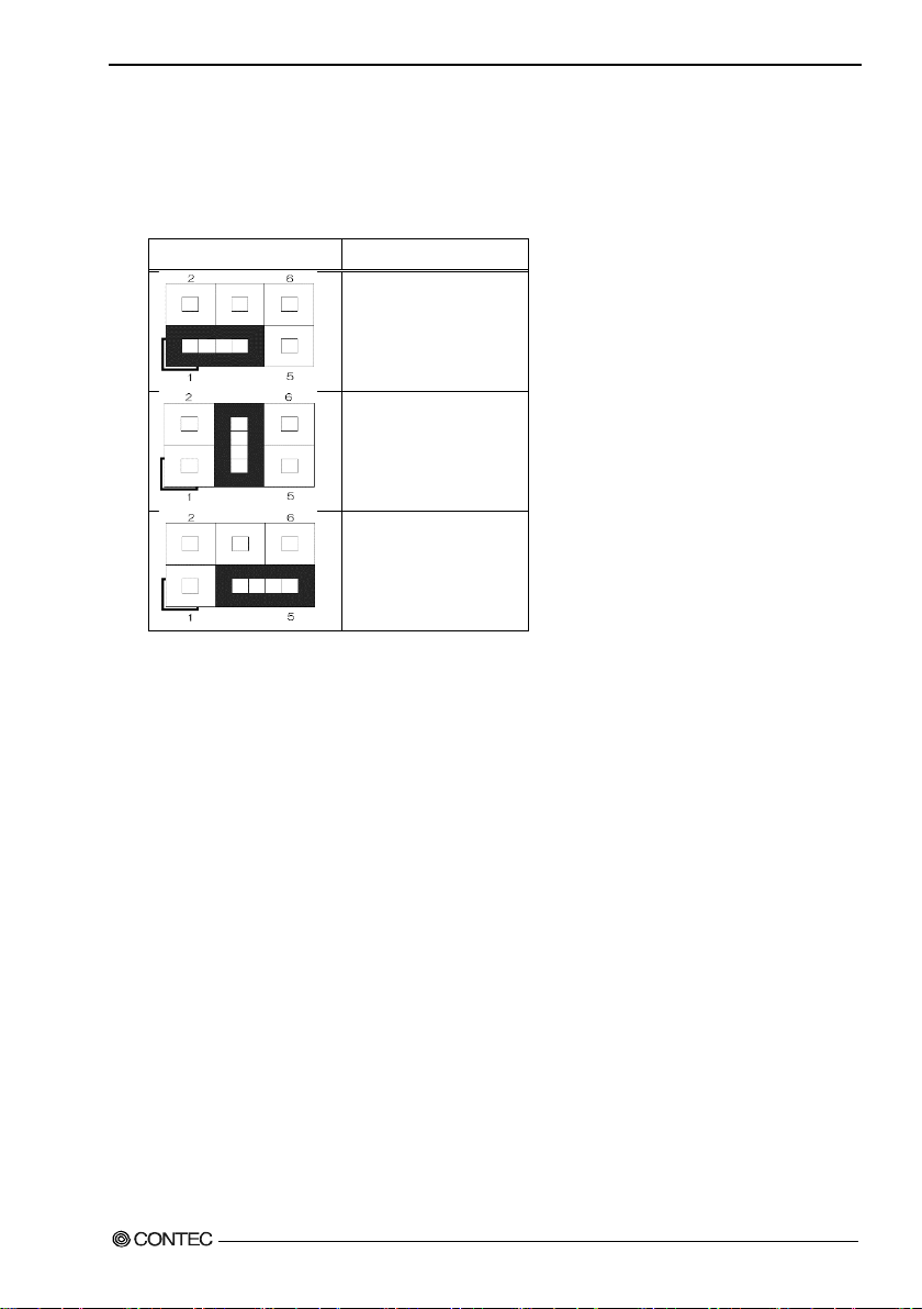
■COM2 RI functio n s etting : JP3
This enables the se ttin g of th e RI function of the COM2 port. RI is set in the f actory settings.
Table 3.5 COM2 RI setting : JP3
+5V
(1-3 short)
RI Signal
(Factory defau lt sett in g)
+12V
(3-5 shrot)
24 User’s Manual
Page 32
3.Hardware setup
JP4
Function
■COM1 RI functio n s etting : JP4
This enables the se ttin g of th e RI function of the COM1 port. RI is set in the f actory settings.
Table 3.6 COM1 RI setting : JP4
+5V
(1-3 short)
RI Signal
(Fact or y de f aul t se tt ing)
+12V
(3-5 shrot)
User’s Manual
25
Page 33

3.Hardware setup
Pin
Signal
Pin
Signal
1
+3V
13
+3V
2
+3V
14
-12V
3
GND
15
GND
4
+5V
16
PS_ON
5
GND
17
GND
6
+5V
18
GND 7 GND
19
GND
8
PW_OK
20
-5
9
5V_SB
21
+5V
10
+12V
22
+5V
11
+12V
23
+5V
12
+3V
24
GND
Pin
Signal
1
GND
2
GND
3
+12V
4
+12V
4
3 2 1
24
12
13
1
◆Mother board internal connector
■ATX power-supply connector : J10/J13
Conne ct t h e ATX po we r co nnect or, observing t he correct or ie nt a t i o n.
J10: ATX 12V power-supply connector
J13: ATX 24 pin connector
Figure 3.5 ATX power supply connector
Table 3.7 J13
Table 3.8 J10
Both J10 and J13 are absolutely necessary power supplies for operation.
Turning on the power for only one of these may dama ge the system.
26 User’s Manual
Page 34
3.Hardware setup
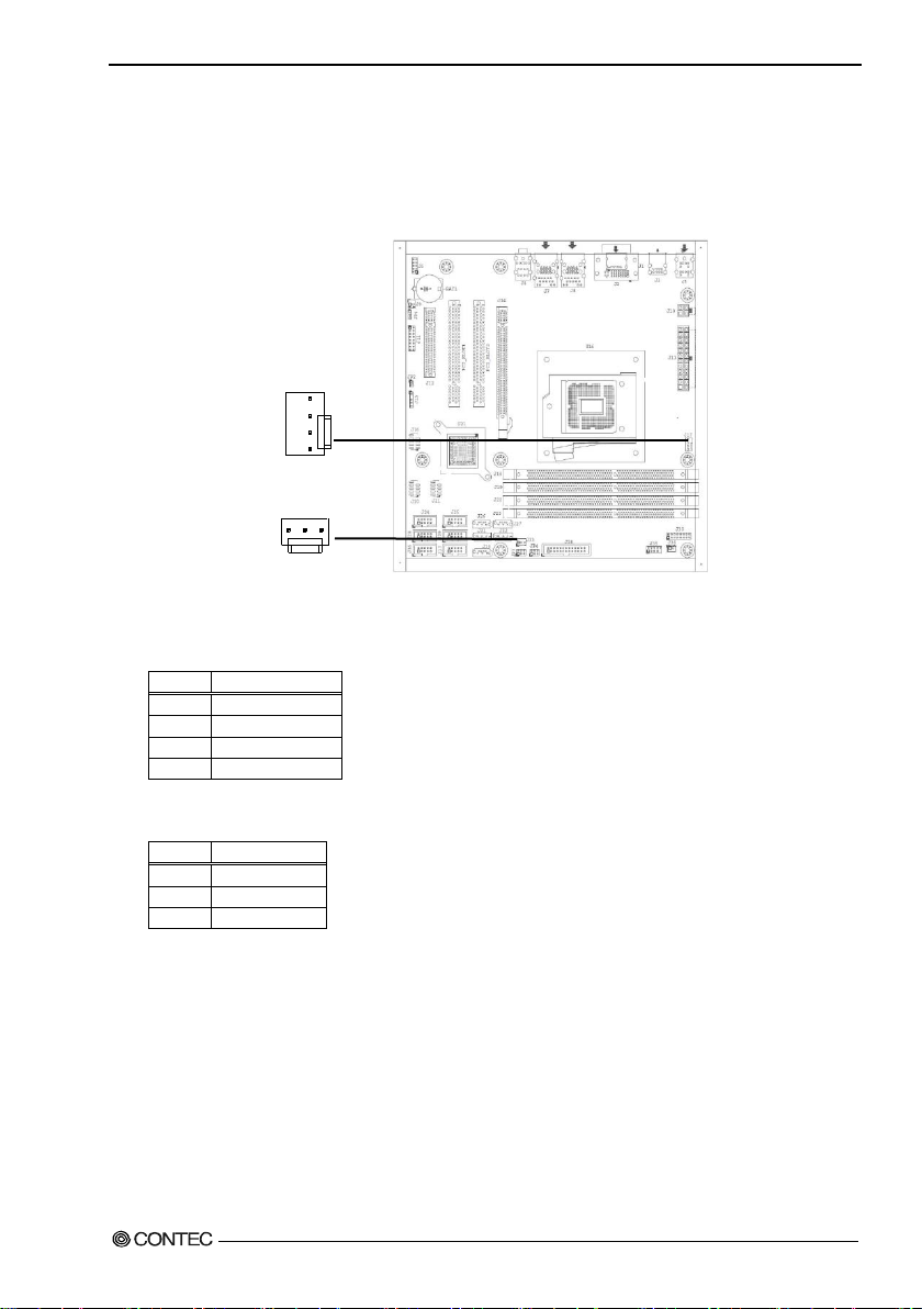
Pin
Signal
1
GND 2 +12V
3
SENEOR
4
CONTROL
Pin
Signal
1
GND
2
+12V
3
SENEOR
3 1 1 4
J17
J33
■Fan power supply connector : J17/J33
Conne ctors for c on necti n g a co oling fa n.
A fan wit h a s pe e d s e n sor can be u se d.
Figure 3.6 Fan power supply connector
Table 3.9 J17
Table 3.10 J33
User’s Manual
27
Page 35
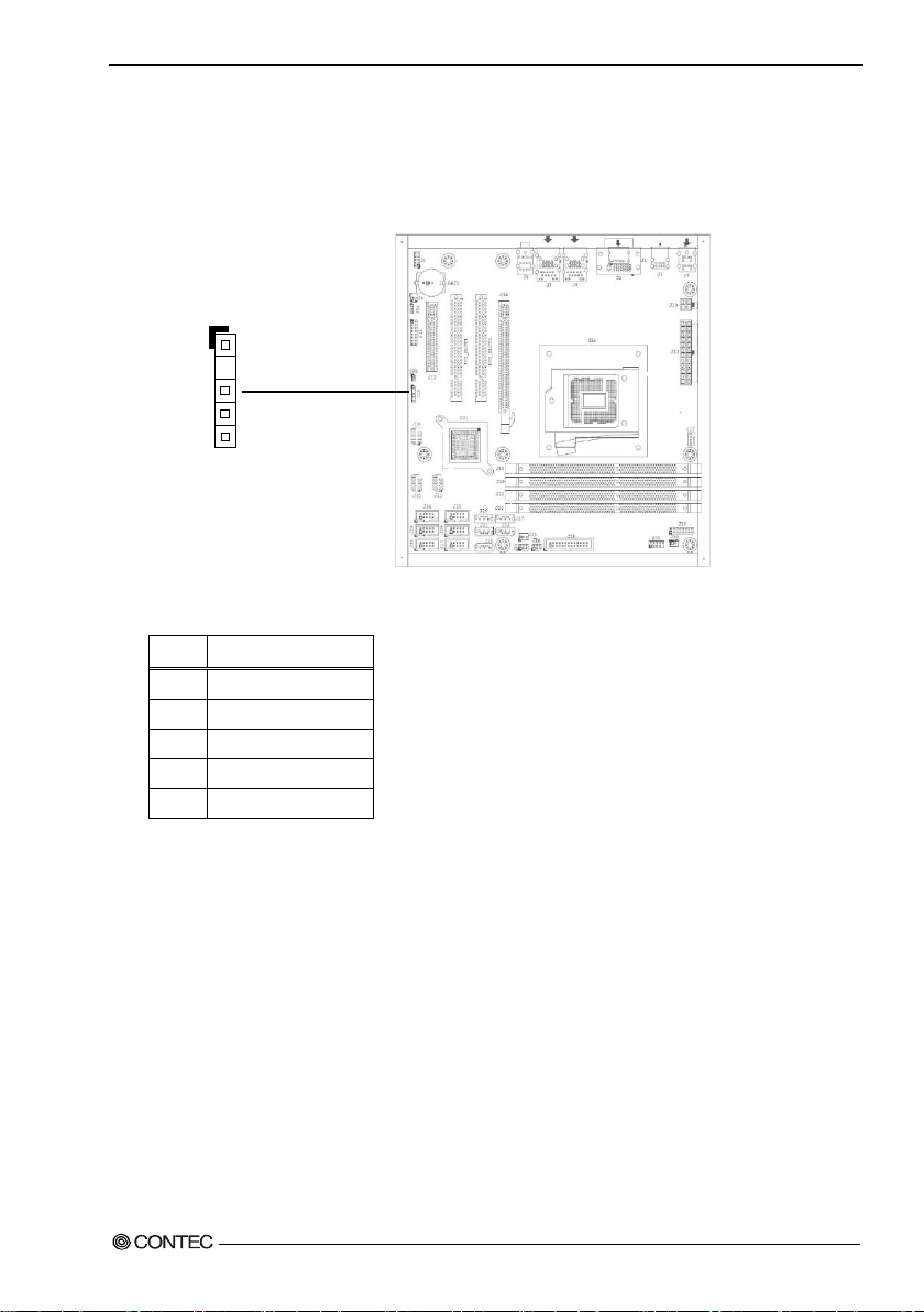
3.Hardware setup
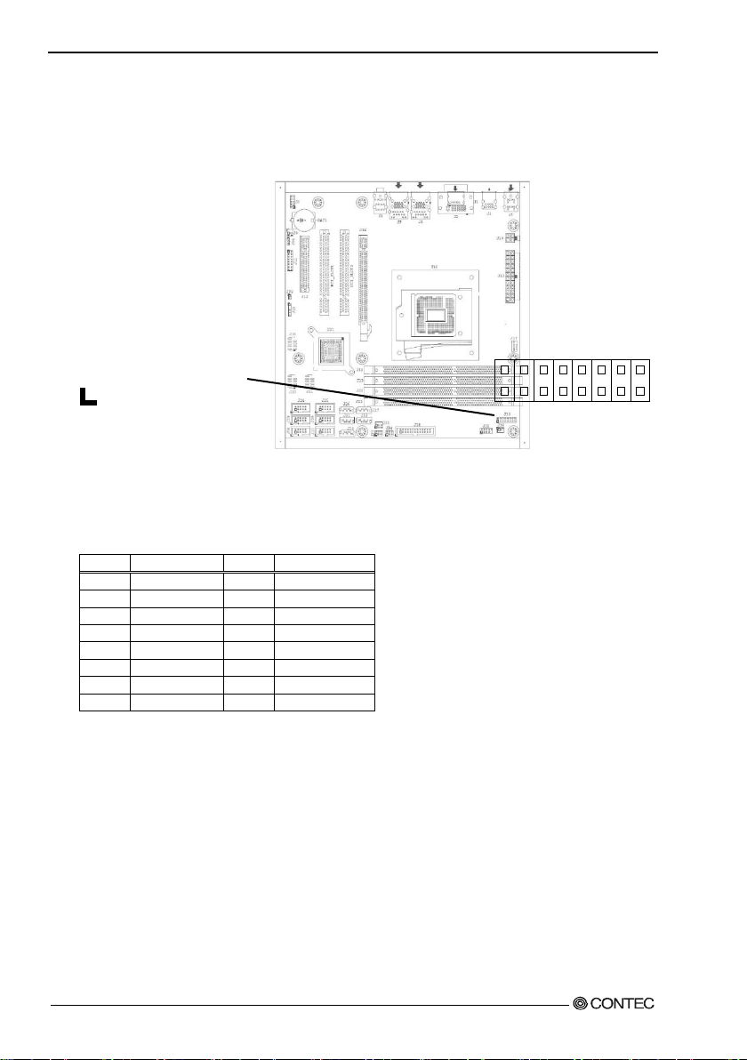
Pin
Signal
Pin
Signal
1
+5V 9 GPIO
2
+12V
10
GPIO
3
GPIO
11
GND
4
GPIO
12
GND
5
GPIO
13
RSTBTN
6
GPIO
14
GND 7 GPIO
15
PWRBTN
8
GPIO
16
NC
16
15
2 1
■Digital I/O connector : J30
This connects to the digital I/O connector at the rear of the main unit.
Fo r details, refer to Chapter 5 ”Functions of Each Unit” - “Digital I/O Interface”.
Figure 3.7 Digital I/O connector
Table 3.11 J30
28 User’s Manual
Page 36

3.Hardware setup
Pin
Signal
Pin
Signal
1
+5V 6 USB +
2
+5V 7 Ground
3
USB -
8
Ground
4
USB -
9
Key (No Pin)
5
USB +
10
N/C
■Internal USB con nect or : J16,J20,J21
Connectors for connecting the USB connector on the front panel of the case with an USB extension
bracket.
For the VPC-3000 series, J21 is already connected to the USB conne c tor on the front panel by a special
cable.
Both J16 and J20 connectors connect nothing in factory setting.
J16
10
9
J20
10
9
J21
10
1 2
1 2
9
Figure 3.8 internal USB connector
Table 3.12 J16,J20,J21
1 2
User’s Manual
29
Page 37
3.Hardware setup
Pin
Signal
Pin
Signal
RESET SW
HDD LED
POWER SW
POWER LED
16
15
2 1
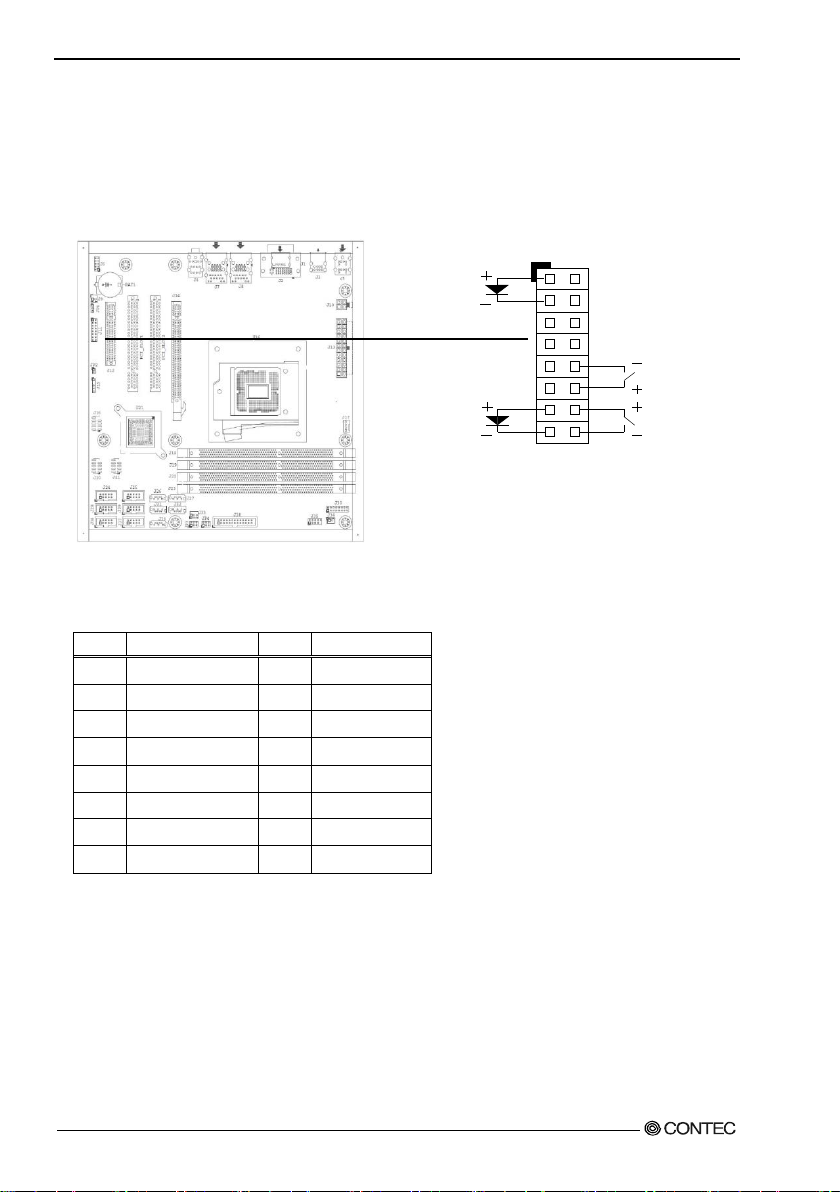
■Front panel connecto r : J11
A conne ctor for c on necti n g t h e po w er swit c h, reset switch, power LED, HDD LED, etc. at the front of the
case.
For the VPC-3000 series, they are already connec ted on the front panel by a special cable.
Figure 3.9 internal front pan e l connector
Table 3.13 J11
1
PWR_LED(+)
2 Speaker(+) 10 Power On(-)
3 PWR_LED(-) 11 LAN2_ACT
4 N/C 12 Power On(+)
5 LAN1_ACT 13 HDD_LED(+)
6 N/C 14 Reset(+)
7 LAN1_LINK 15 HDD_LED(-)
8 Speaker(-) 16 Reset(-)
9 LAN2_LINK
30 User’s Manual
Page 38

3.Hardware setup
RS-232C
Pin
Signal
Pin
Signal
1
DCD 6 CTS
2
DSR 7 DTR
3
RXD 8 RI 4 RTS 9 Ground
5
TXD
10
NC
J24/COM6
J28/COM4
J36/COM1
J25/COM5
J29/COM3
J37/COM2
■COM port connector : J24/J25/J28/J29/J36/J37
These are connected to the COM1, COM2, COM3 and COM4 connectors at the rea r of th e m a in unit.
2
10
2
10
1
2
1
2
1
9
10
9
10
9
Figure 3.10 COM port connector
Table 3.14 J24,J25,J28,J29,J36,J37
1
2
2
9
10
1
1
9
10
9
User’s Manual
31
Page 39

3.Hardware setup
1
MIC2-L
6
MIC2 Sense resistor
2
GNDAU
7
SENSE-B
3
Mic2-R_Conn
8
NC
4
Pull-high resistor
9
Line2-L_Conn
5
Line2-R_Conn
10
Line2 Sense resistor
J6
■Audio connector : J6
This con nector connects the fron t-face audio connector and the audio extension bracket.
Neither of these is connected on the VPC-3000 series.
10
2 1
9
Figure 3.11 Audio connector
Table 3.15 J6
Pin Signal Pin Signal
32 User’s Manual
Page 40
3.Hardware setup
1
SMB_CLK
2
N/C 3 Ground
4
SMB_DAT
5
+5V
J15
■System management bus c onnector : J15
This is a general-purpose communication bus connector between the devices used to manage the system
and the power supply. It is not connect ed on the VPC-3000 series.
1
5
Figure 3.12 System management bus connector
Table 3.16 J15
Pin Function
User’s Manual
33
Page 41

3.Hardware setup
1
Strobe#
14
Auto Form Feed#
2
Data0
15
Error#
3
Data1
16
Initialization#
4
Data2
17
Printer Select IN#
5
Data3
18
Ground
6
Data4
19
Ground
7
Data5
20
Ground
8
Data6
21
Ground
9
Data7
22
Ground
10
Acknowledge#
23
Ground
11
Busy
24
Ground
12
Paper E m pty
25
Ground
13
Printer Select
26
NC
J38
■Parallel port co nnector : J38
This is c on nected to the printer port con nector on t h e rea r of the VP C -3000.
2
1
26
25
Figure 3.13 Parallel port conn ector
Table 3.17 J38
Pin Signal Pin Signal
34 User’s Manual
Page 42
3.Hardware setup
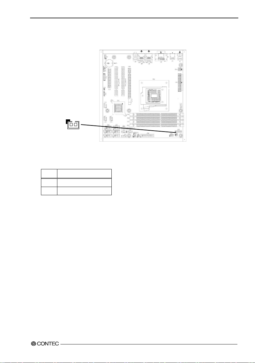
1
Ground
2
Signal
J34
2 1
■Case open connecto r : J34
J34 connect nothing in factry setting.
Figure 3.14 Case open connector
Table 3.18 J34
Pin Signal
User’s Manual
35
Page 43

3.Hardware setup
Push the lock and the knob pul ls
Lock
◆Attaching the hard disk
(1) Rem ove the r e mova ble ca s e from the dri v e bay.
forward.
Figure 3.15 Extension and replacement of the hard disk (1)
36 User’s Manual
Page 44

3.Hardware setup
The four screws
Tigh ten four screw f rom a base to fi x the
hard disk .
(2) Remove and replace the HDD in the remove d 5-inch bay.
Figure 3.16 Attaching the hard disk in the drive bay (2)
User’s Manual
37
Page 45
3.Hardware setup
Push it in fir mly until it connect s to the
If the Removable is up p er an d l owe r
(3) Reverse the removal procedure and re-insert it.
The replacement HDD must be an S-ATA drive. N o te the s peci fication.
conne c tor at the back.
※
opposite, it cannot be connected.
Figure 3.17 Extension and replacement of hard disk (3)
38 User’s Manual
Page 46
3.Hardware setup
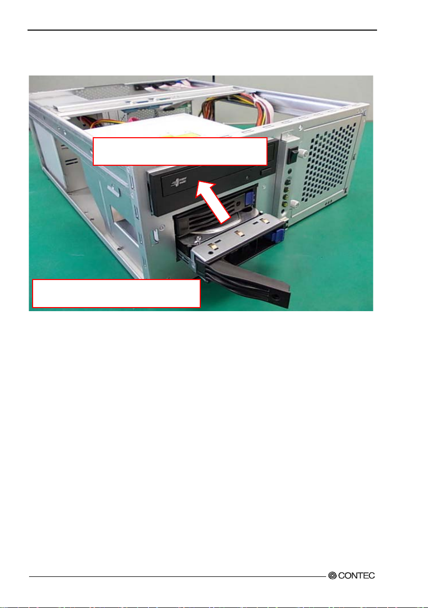
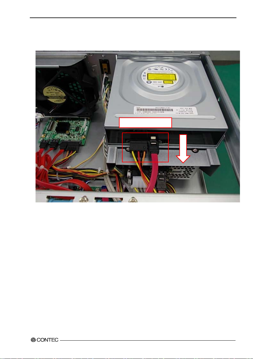
Remove al l cables.
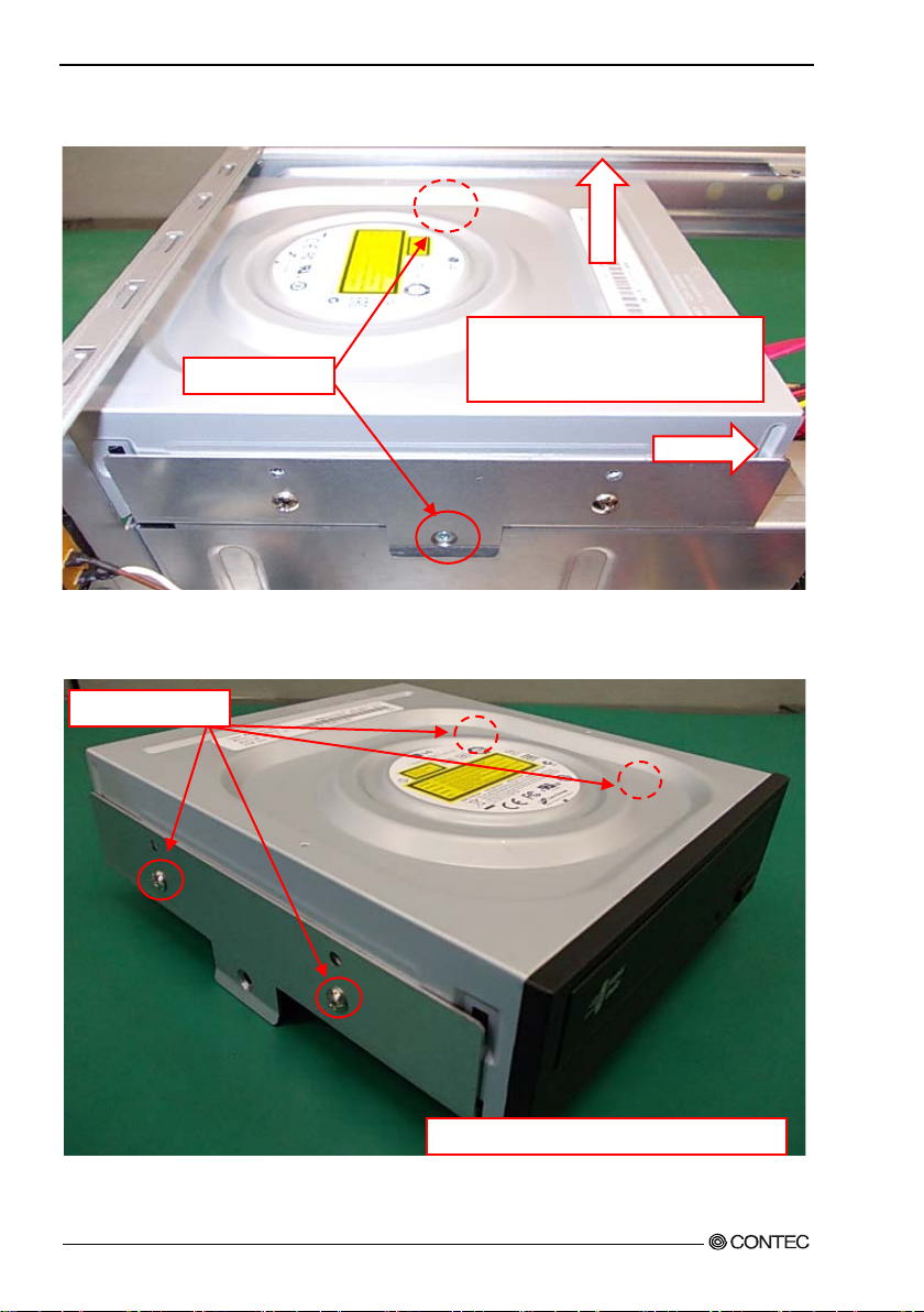
◆Replacing the optical drive
(1) Remove all cables o f th e opti ca l dr ive.
Figure 3.18 Removin g all cables of th e optical drive (1)
User’s Manual
39
Page 47
3.Hardware setup
The two screw
It moves t o horizonta l direction,
The four screws
Remove f our screws of the bracket side.
(2) Remov e two scre w s fr o m t h e bra cket o f th e o ptical drive. It m o ve s to horizo nt a l di recti o n, a n d it
detaches it to the vertical direction.
and it de taches it to th e vertical
direction.
Figure 3.19 Removing the bracket for the optical drive
(3) Remove four scr ews and remove the optical drive.
Figure 3.20 Removing th e optical drive
(4) Reverse the removal procedure and re-insert it.
40 User’s Manual
Page 48

3.Hardware setup
J22
J23
J18
J19
◆Attaching the exten sion memory
(1) Insert e x pa nsio n m e mor y i nto the me m ory slot.
For DIM M A an d DI MM B, u se me m ory com pl i a nt with th e s p e cification.
Figure 3.21 Attaching the extension memory
(2) Lock the momory into the slot.
Figure 3.22 Lock the extension memory
User’s Manual
41
Page 49

3.Hardware setup
Push in the extension board
Screws
◆Attaching the extension board
(1) After unscrew t he screw, remove the slot cover in the back of the chassis.
Figure 3.23 Removing the slot cover
(2) The ext en s i o n b oa r d is instal l ed, and i t fi xes with the scr e w .
securely as far as it will go.
Figure 3.24 Attaching the extension board
Please install it v ery care full y mig ht int er face wit h th e bend of various cables in t he case when you
install it according to the size of the extension board that installs it.
■Maximum dimensions of boards that can be installed
176mm(L)×110mm(H) (All PCI Express x16,PCI Express x4,PCI bus)
(3) Reverse the at tachment procedure and remove it.
42 User’s Manual
Page 50

3.Hardware setup
Grasp the handle of the fan filter , and then pull i t out.
◆Removing the dustproof filter
(1) Loosen the knurled scr ews, and then open the front fan cover.
Figure 3.25 Removing the dustproof f ilter (1)
(2) Reverse the remov al procedure and re-insert it.
User’s Manual
43
Page 51
3.Hardware setup
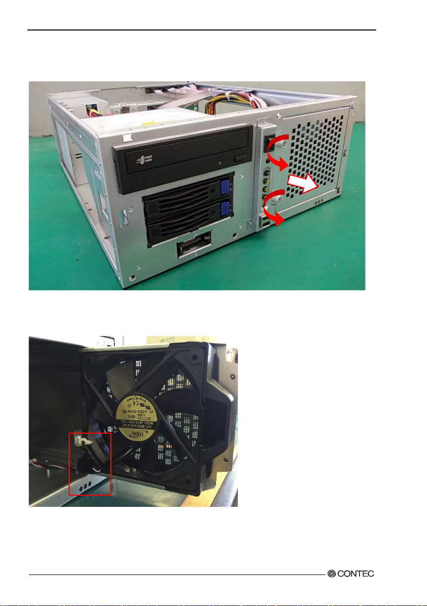
◆Replacing the front fan
(1) Loosen the knurled scr ews, and then open the front fan cover.
Figure 3.26 Removin g th e f r ont fan (1)
(2) Remove the fan cable and fa n c on nect or.
44 User’s Manual
Page 52

3.Hardware setup
lock
Figure 3.27 Removin g th e front fan (2)
(3) Push the lock and th e k no b pu l l s forward.
Figure 3.28 Removin g th e f r ont fan (3)
User’s Manual
45
Page 53

3.Hardware setup
Vertical installation】
Horizontal installation】
◆Attaching the wall mount stand
(1) Secure the wall mou nt sta nd with the four supplied screws.
Figure 3.29 Attac hing t he wall mount sta n d
After attaching the stand, the wall mount stands are secured to the chassis.
During attaching the wall mount stands, ensur e that the upper and lower it.
【
【
◆Removing the wall mount stand
(1) Remove the four screws anchoring the wall mount stands.
(2) Remove the wall mount stands from the chassis.
46 User’s Manual
Page 54

3.Hardware setup
Fix by sc rew
FG cable
◆FG connection
(1) Use a screw to fix the FG cable in place in th e position shown in the fol lowing figure.
Figure 3.30 FG Connection
User’s Manual
47
Page 55

3.Hardware setup
◆Installation requirements
In order to enjoy reliable use of the VPC-3000 ser ies, maintain the following conditions.
■Installabl e dire ctio n s
Please do not use by the follo win g ins talla ti o n s, and do not set it up in other dir e ction s.
Figure 3.31 Installable direction
48 User’s Manual
Page 56

3.Hardware setup
■Spac e be t w ee n t h e main unit and it s su rr oundi n g s
The main unit of the VPC-3000 series is equipped with air vents and fans for regulating temperature. In
order to ens ure space f or air vents and cables, keep distance described in the following be tween the
front/rear and surrounding equipment, walls, etc.
Note that in the installation location, air must be able to circulate. Please adjust the flow of air so as not to
exce ed the s pecif i catio n temp er a t u re of the pr oduct.
Moreover, the unit can not be used in an enclosed space.
Figure 3.32 Installation condition
User’s Manual
49
Page 57

3.Hardware setup
The two screws
◆Removing the DIO cover
This cover is used for protecting the DIO pins.
(1) Removing the DIO cover sc rews
Remove the two screws anchoring the chassis to the DIO cover and remove the DIO cover .
Fui
Figure 3.33 Removin g th e DIO cover
(2) Attaching the DIO pin cover
Reverse the procedure of removing the DIO pin cover and attac h it.
50 User’s Manual
Page 58

3.Hardware setup
◆Option: Attaching and removing the mirror card
(1) Remove all cables and such connected to the m irror card.
Figure 3.34 Removin g all cables
※Starting fro m the left, th e Seria l -ATA cables from the upper HDD, lower HDD, mother board, and
power su p ply.
※Dur ing connec t i on, ensure that t he Ser ia l-AT A c abl es of the upper and lower HDDs are not reversed.
User’s Manual
51
Page 59

3.Hardware setup
The four screws
The two knurled screws
(2) Loosen the knurled scr ews, and then open the front fan cover.
Figure 3.35 Opening the front fan cover
(3) Remove the screws that are holding the mirror card in place, and then remove the mirror card.
Figure 3.36 Removing the mirror ca rd
(4) Asse m bly is the re v erse of removal.
※During attaching, ensure that the direction and the upper an d lower the mirror card.
52 User’s Manual
Page 60
4.BIOS setup
Key
Function
Up Arrow
Move to the pre vi ous ite m
Down Arrow
Move to the next item
Left Arrow
Move to the item on t he left (menu bar)
Right
Move to the item on the right (menu bar)
Main Menu : Quit without saving cha nges
Move Enter
Move to the item you desired
+ key
Increase t h e nume r ic value or make change s
- key
Decr ease th e num er ic valu e or make cha nges
F1 key
General help on Setup navigation keys
F2 key
Load previous values from settings
F3 key
Load the fail-safe defaults from BIOS default table
F4 key
Save all the FLASH ROM changes and exit
C
A
UTION
Version 2.15.1236. Copyright (C) 2012 American Megatrends, INC.
4.BIOS setup
BIOS setu p sets various setting during startup. When usi ng the system for the first time, besure to run
BIOS setup. Once set up, the sp eci fie d details will be backed up.
Do not change it e m s n ot d e scr i b e d i n th is document.
The system may become unstable and may not start up.
Starting the set up screen
When you turn on the power to the system, if the system is functioning normally, the “Press DEL to enter
SETUP” sc reen appe a rs. Then press the <DEL> key. After a few seconds, a se tup utilit y can be started.
SMB-MQ871-LLVA BIOS Ver. 1.10
Press <CTRL + P> to Enter MEBX setup menu
Press <DEL> or <ESC> to enter setup.
Figure 4.1. Initial screen
Setup operations
Normal ly use the arrow keys to move be tween items and press <En ter> to make selections. Use the + and
- keys to c ha nge th e va lu e s o f items. Press <F1 > t o display help and <Esc> to exit setup. A table of the
setup program keyboard operations is shown bel ow.
Table 4. 1 Setup operations
ESC
User’s Manual
Submenus : Exit Curre nt page to the ne xt higher lvel menu
53
Page 61

4.BIOS setup
Main Configuration Boot Security Exit
Main menu
When you sta rt the s etup pro gr am (Aptio Setu p Uti l i ty), th e main menu is displ a y e d on the screen. You
can move to the tabs of the differen t items by pressing the right and left arrow keys.
Project Name
BIOS Verion & Build Date
Processor Information
Name
Brand String
Total Memory
Memor y Frequ en c y
PCH Information
Name
PCH SKU
ME Firmware Mod e
ME FW Version
ME Firmware SK U
System Date
System Tim e
Access Level
Figure 4.2. Example of main window screen
SMB-MQ871-LLVA
BIOS Ver. 1.10 (04/15/2015 15:20:1 9)
Haswell
Intel(R) Core(TM) i7-4770S CPU @ 3. 10G H z
4096 MB (DDR 3)
1333Mhz
LynxPoint
Q87
Normal Mode
9.0.30.1482
5MB
[Thu 04/16/2015]
[08 : 49 : 14]
Administrator
Setting of the date and time
In order t o s et th e da te and tim e of the cal e nda r clock on the VPC-1500 series, follow the following steps.
1. Select “Standard CMOS Features” menu from the setup screen.
2. Select date (Date :) items by pressing the <Page Up> and <Page Down> keys. You can navigate
through items by pressing the cursor keys <
3. Save setup chan ge s with “Save Ch a nges and Reset” (pressing the <F4> key) and exit.
54 User’s Manual
>, <>.
Page 62

4.BIOS setup
Password Description
Set Administrat or Password
Setting of the password
Operating at the Setup utility
Administrator
You can change all settings.
User
You can a c ce s s all s etting s , bu t you cann ot m o dify any s et t i ng other
than removing your password.
CAUTION
Setting of the start password
After set ting a star tup pas s w ord, you mu s t e nter the pa ssword when you boot the system and run setup.
The password can protect system information and files, limiting their use by other users.
Once you register a password, you will not able to clear password features without the password. Pay
careful enough attention in handli n g your pa s s word.
If only the Admin istrator’s password is set,
then this only limits ac c ess to Set up a nd is
only asked for when entering Setup.
If only the User ’s password is set, th en this
is a power on password and must be entered to
boot or enter Setup. In Setup the User will
have Administrator rights.
The pa s s wor d l e n gth must be
in the fol l o w ing rang e :
Minimum length 3
Maxim um length 20
Admi ni str a tor Pa s s word
User Password
HDD Security Configuration:
P0: WDC WD 2503AB
Figure4.3 Password menu display cases
Table 4. 2. Setting of th e password
User’s Manual
55
Page 63

4.BIOS setup
Boot Option #1
[CD/DVD: HL-DT-ST DVDRA ATAPI]
Adm inist rator Pass wo rd
1. Select “Administrator Password” on the “Security tab”.
2. “Crea te New Password” is displ aye d, so type a password between 3 and 20 characters in length, and
then p ress the <Enter> ke y.
3. “Confirm New Password” is displayed, so type the same password that you did in step 2, and then
press the <Enter> key.
User Password
1. Select “User Password” on the “Security” tab.
2. “Crea te New Password” is displ aye d, so type a password between 3 and 20 characters in length, and
then p ress the <Enter> ke y.
3. “Confirm New Password” is displayed, so type the same password that you did in step 2, and then
press the <Enter> key.
* You cannot set a User Password if an Administrator Password has not been set.
Release of set the passwo rd
Althou gh the method for doing thi s i s th e same as setting a passwo r d , w he n you ent er t h e password, press
the <Enter> key witho ut entering anything , and the password will be remo ved. Removing the
Administrator Password and the user password works the same way.
Changing to the device boot order
It is possible to change device boot order.
Boot Option #2
Figure 4.4 Changing to the device boot or der
1. Sel ect “FIXED BOOT ORDER Priorities” menu from “Boot” tab.
2. Change the settings for “Boot Op ti on #1”, “Boot Otpion #2”, and etc.
3. In order to assign top priority to booting from the CD-ROM, move the cursor to the “Boot Opt ion
#1” item and change the setting to “CD/DVD:…”. (Confirm your choice and setting by pressing the
<Enter> key.)
4. After setting the desired order, press the <Esc> key and move to “Exit” tab.
5. Save setup chan ge s with “Save Ch a nges and rese t” and exit.
56 User’s Manual
[Hard Disk: WDC WD2503A BYZ (251.0GB) ]
Page 64

4.BIOS setup
Main Configuration Boot Security Exit
SATA Configuration
Selection of SATA devices
SATA Controller(s)
SATA Mode Sele ctio n
SATA Controller Speed
Serial ATA Port 0
Port 0
Hot Plug
External SATA
SATA Device Type
Figure 4.5 Selection of SATA devices
1. Sel ect “SATA Configuration” menu from “Config ur ation” tab.
2. Sel ect “SATA Mode Selection” item from “SATA Configuration” window.
3. Change the setting for “SATA Mode Selection”. (Options ar e “I D E”, “RAID”, “AHCI”)
4. After setting th e de s ir e d order, press th e <Esc> k ey an d m ove to “E xit ” ta b.
5. Save setup changes with “Save Changes and Reset” and exit.
[Enabled]
[AHCI]
[Default]
WDC WD2503ABYZ
(251.0GB)
[Enabled]
[Disabled]
[Disabled]
[Hard Disk Drive]
User’s Manual
57
Page 65

4.BIOS setup
Power Control Configuration
C
AUTION
Setting for the power on (AT power operation) by the AC power-supply turning on
Enable H ibernation
ACPI Sleep State
Power Failu re
Wake system with Fixed Ti me
Wkae up Day of Month
Wake up ho ur
Wake up minute
Wake up second
Wake on Ring
Figure 4.6 Setting for the power on by the AC power-supply turning on
1. Select “Powe Control Configuration” menu from “Configuration” tab.
2. Select “Powe r Failure” item from “Pow er Control Configuration” window.
3. Change from “Always off” to “Always on”.
4. After setting the above-mentioned 3, pres s the <Esc> key and move to “Exit”.
5. Save setup changes with “Save Changes and Reset” and exit.
[Enabled]
[S3 only (Suspend to ...]
[Alway s off]
[Disabled]
0
0
0
0
[Disabled]
◆Factory default setting
This section de scri bes the CMOS Setup Uti lit y’ s fact or y default s ettin g s.
By selecting “Load Optimized Defaults” in the Main window of the CMOS Setup Utility, you ca n restore
our fact ory sett ings. For opera t ional in str ucti on s , f ollow th e follow ing step s.
1. Sel ect “Load Optimized Defaults” menu from the setup screen.
2. Yo u a re prompte d to confirm that you are restoring to initial conditions. Press the <Y> and <Enter>
keys.
3. Save setup changes with “Save & Exit Setup” and exit.The followi ng section describes parameters
for the factory default settings of each setting in the CMOS Setup Utility.
Do not change settin g s other than the CMO S S etup Utility settin g s specifically describ ed in thi s
docu m ent . Th e O S may not fu n ction n ormall y ot h erwise .
We assume no responsibility for trouble caused by changing settings other than the CMOS Setup
Utility settings specified.
58 User’s Manual
Page 66

4.BIOS setup
Main
Project Name
BIOS Verion & Build Date
Processor Information
Name
Brand String
Total Memory
Memor y Frequ en c y
PCH Information
Name
PCH SKU
ME Firmware Mod e
ME FW Version
ME Firmware SK U
System Date
System Tim e
Access Level
Figure 4.7 Main s et t in g s creen
* The displa y of the Main tab varies depending on the pro duct configur a tion.
SMB-MQ871-LLVA
BIOS Ver. 1.10 (04/15/2015 15:20:1 9)
Haswell
Intel(R) Core(TM) i5-4570TE CPU @ 2.70GHz
4096 MB (DDR 3)
1333Mhz
LynxPoint
Q87
Normal Mode
9.0.30.1482
5MB
[Thu 04/16/2015]
[08 : 49 : 14]
Administrator
User’s Manual
59
Page 67

4.BIOS setup
CPU Configuration
CPU Configuration
CPU C states
[Disabled]
Configuration
Chipset Configurati on
LAN Configuration
Graphics Configuration
PCI/PCIE Configuration
SATA Configuration
USB Configuration
Power Control Configuration
Super IO Configuration
H/W Mo ni t or
Serial Port Console Redirection
Figure 4.8 Configuration settin g screen
◆CPU Configuration
Intel(R) Core(TM) i5-4570TE CPU @ 2.70GHz
CPU Signatur e
Max CPU Speed
Min CPU Speed
Processor Co res
Intel HT Technology
Int el VT-x Technology
Intel SMX Technology
64-bit
EIST Technology
CPU C3 state
CPU C6 state
CPU C7 state
Hyper threading
Active processor Cores
Intel Virtualization Technology
EIST
Turbo Mode *1
Figure4.9 CPU C onfi guration setting screen
*1 This is no t di s pl a y e d w h en a Celeron CPU is installed.
*2 This is no t su p p or ted whe n a Celero n C P U is installed.
306c3
2700 MHz
800 MHz
2
Supported
Supported
Supported *2
Supported
Supported
Supported
Supported
Supported *2
[Enabled]
[All]
[Enabled]
[Enabled]
[Enabled]
60 User’s Manual
Page 68

4.BIOS setup
Chipset Configura tion
AMT Conf iguration
Memory Information
◆Chipset Configuration
High Precision Timer
Azalia
VT-d *1
Port 80h Redirection
AMT Configuration
Memory Configuration
Figure 4.10 Chip s et C onfiguration set t in g screen
*1 This is not displayed when a Celeron CPU is installed.
AMT Conf iguration
Intel A MT
Un-Configure ME
Disabl e M E
Figure 4.11 AMT Configuration setting s creen
Memory Configurati on
Total Memory
DIMM#0
DIMM#1
DIMM#2
DIMM#3
Figure 4.12 Memory C onfiguration setting screen
[Enabled]
[Enabled]
[Enabled]
[LPC Bus]
[Enabled]
[Disabled]
[Disabled]
4096 MB (DDR 3)
4096 MB (DDR 3)
Not Pre s ent
Not Pre s ent
Not Pre s ent
User’s Manual
61
Page 69

4.BIOS setup
LAN Configuration
Graphics Config uration
◆LAN Configuration
Launch PXE OpROM policy
Intel (R) Ethernet Connect ion I218-LM
Intel LAN I-218LM Controller
Wake on LAN
Intel (R) Ethernet Connect ion I210AT
Intel LAN I210-AT Controller
Wake on LA N I210-AT
Figure 4.13 LAN C onfiguration sett in g s creen
◆Graphics Configuration
Primary Display
Primar y PEG
Primary PCIE
Internal Graphics
Aperture Size
DVMT Pre-Allocated
DVMT Total Gfx Mem
Primary IGFX Boot Display
Secondary IGFX Boot Display
Figure 4.14 G raph ics Configuration setting screen
[Disabled]
[Enabled]
[Disabled]
[Enabled]
[Disabled]
[AUTO]
[AUTO]
[AUTO]
[AUTO]
[256MB]
[32M]
[256M]
[CRT]
[DVI]
62 User’s Manual
Page 70
4.BIOS setup
PCI/PCIE Configurati on
CPU PCI Express Configuration
PCH PCI Express Configuration
◆PCI/PCIE Configuration
PCI Common Settings
PCI Latency Timer
PCI Express Settings
Maximum Payload
Maximum Read Request
CPU PCI Express Configuration
PCH PCI Express Configuration
Figure 4.15 PCI/PCIE Configuration setting screen
CPU PCI Express Configuration
PEG0
PEG0 - G e n X
PEG0 –ASPM
PEG1
PEG1 - G e n X
PEG1 –ASPM
PEG2
PEG2 - G e n X
PEG2 –ASPM
Enable PEG
Figure 4.16 CPU PCI Express Configurat ion setting screen
[32 PCI Bus Clocks]
[AUTO]
[AUTO]
Not Pre s ent
[Auto]
[Disabled]
Not Pre s ent
[Auto]
[Disabled]
Not Pre s ent
[Auto]
[Disabled]
[Auto]
PCH PCI Express Configuration
PCI Express Root Port 1
PCIE Por t 3 is assigned to I218LM
PCI Express Root Port 4 fo r I210AT
PCI Express Root Port 5
Figure 4.17 PCH PCI Express Configuration setting screen
User’s Manual
63
Page 71

4.BIOS setup
PCI Express Root Port 1
[Enabled]
Intel LAN I210-AT Controller
[Enabled]
PCI Express Root Port 5
[Enabled]
SATA Configuration
PCI Express Root Port 1
ASPM
PCIe S p eed
Figure 4.18 PCI Expres s R oot Port 1 setting screen
PCI Express Root Port 4 fo r I210AT
ASPM
PCIe S p eed
Figure 4.19 PCI Express Root Port 4 for I 210AT setting screen
PCI Express Root Port 5
ASPM
PCIe S p eed
Figure 4.20 PCI Expres s R oot Port 5 setting screen
◆SATA Configuration
SATA Controller(s)
SATA Mode Sele ctio n
SATA Controller Speed
Serial ATA Port 0
Port 0
Hot Plug
External SATA
SATA Device Type
Serial ATA Port 1
Port 1
Hot Plug
External SATA
SATA Device Type
Serial ATA Port 2
Port 2
Hot Plug
[Disabled]
[Auto]
[Disabled]
[Auto]
[Disabled]
[Auto]
[Enabled]
[AHCI]
[Default]
ST500LT012-1DG (500.1GB)
[Enabled]
[Disabled]
[Disabled]
[Hard Disk Drive]
ST500LT012-1DG (500.1GB)
[Enabled]
[Disabled]
[Disabled]
[Hard Disk Drive]
ATAPI iHAS12 ATAPI
[Enabled]
[Disabled]
64 User’s Manual
Page 72

4.BIOS setup
External SATA
[Disabled]
USB Configuration
SATA Device Type
Serial ATA Port 3
Port 3
Hot Plug
External SATA
SATA Device Type
Serial ATA Port 4
Port 4
Hot Plug
External SATA
SATA Device Type
Serial ATA Port 5
Port 5
Hot Plug
External SATA
SATA Device Type
Figure 4.21 SATA Configuration sett in g scr een
◆USB Configuration
[Hard Disk Drive]
Empty
[Enabled]
[Disabled]
[Disabled]
[Hard Disk Drive]
Empty
[Enabled]
[Disabled]
[Disabled]
[Hard Disk Drive]
Empty
[Enabled]
[Disabled]
[Disabled]
[Hard Disk Drive]
Figure 4.22 USB Con figuration settin g screen
User’s Manual
USB Devices:
1 Keyboard, 2 Hubs
Legacy USB Support
XHCI Mode
XHCI Hand-off
EHCI Hand-off
USB Mass Storage Driver Support
PCH USB Configuration
[Enabled]
[Enabled]
[Enabled]
[Enabled]
[Enabled]
65
Page 73

4.BIOS setup
PCH USB Configuration
Power Con trol Configuration
PCH USB Configuration
USB Port #0
USB Port #1
USB Port #2
USB Port #3
USB Port #4
USB Port #5
USB Port #6
USB Port #7
USB Port #8
USB Port #9
USB Port #10
USB Port #11
USB Port #12
USB Port #13
Figure 4.23 PCH USB Conf iguration s ettings s c r ee n
◆Power Control Configuration
Enable H ibernation
ACPI Sleep State
Power Failu re
Wake system with Fixed Ti me
Wkae up Day of Month
Wake up ho ur
Wake up minute
Wake up second
Wake on Ring
Figure 4.24 Power Control Configuration settings screen
[Enabled]
[Enabled]
[Enabled]
[Enabled]
[Enabled]
[Enabled]
[Enabled]
[Enabled]
[Enabled]
[Enabled]
[Enabled]
[Enabled]
[Enabled]
[Enabled]
[Enabled]
[S3 only (Suspend to ...]
[Alway s off]
[Disabled]
0
0
0
0
[Disabled]
66 User’s Manual
Page 74

4.BIOS setup
Super I O Conf igurat ion
◆Super IO Configuration
Serial Port1
Device Settings
Serial Port2
RS-232/422/485 Control Option
Device Settings
Serial Port3
Device Settings
Serial Port4
Device Settings
Serial Port5
Device Settings
Serial Port6
Device Settings
Parall el Port
Device Settings
Watch Dog Timer
Figure 4.25 Sup er I O Conf iguration settings screen
[Enabled]
IO=3F8h; IRQ=4;
[Enabled]
[RS-232]
IO=2F8h; IRQ=3;
[Enabled]
IO=260h; IRQ=10;
[Enabled]
IO=268h; IRQ=11;
[Enabled]
IO=270h; IRQ=10;
[Enabled]
IO=278h; IRQ=11;
[Enabled]
IO=378h; IRQ=7;
[Disabled]
User’s Manual
67
Page 75

4.BIOS setup
Smart CPU Fan Control
[Enabled]
Serial Port Console Redirection
◆H/W Monitor
Smart CP U Fa n Sta rt
CPU Fan Full Speed
Smart System Fan Control
Smart System Fan Star t
System Fan Full Speed
Case Open Warnig
CPU temperature
Syst e m temp er a t u re
CPU Fan Speed
SYS Fan Speed
Vcore
+1.5V
+12V
+5V
+3.3V
VBAT
Figure 4.26 H/W Monitor s et t ings screen
◆Serial Port Console Redirection
20
60
[Enabled]
20
60
[Disabled]
+31 C
+31 C
2184 RPM
766 RPM
+1.704 V
+1.488 V
+11.980 V
+5.061 V
+3.297 V
+3.192 V
COM0
Conso le Re direction
Cons ol e R e direct i o n S et ting s
Figure 4.27 Seria l Port Console Redirecti on settings screen
68 User’s Manual
[Disabled]
Page 76

4.BIOS setup
Boot Configurati on
Boot Option #1
[P0: S T500L T012-1DG1...]
Boot Option #1
[P2: ATAPI iHAS124...]
Boot
Bootup NumLock State
GateA20 Acti ve
Option ROM Messages
INT19 Trap Response
Launch Storage OpROM
Full Screen Logo
Post Report
Summary Screen
Fast Boot
Boot mode select
FIXED BOOT ORDER Priorities
Boot Option #1
Boot Option #2
Boot Option #3
Boot Option #4
Boot Option #5
Boot Option #6
Boot Option #7
Hard Disk Drive BBS Priorities
CDROM/DVD Drive BBS Priorities
Figure 4.28 Boot sett ings screen
[On]
[Upon Reque st]
[Force BIOS]
[Immediate]
[Enabled]
[Disabled]
[Disabled]
[Disabled]
[Disa ble Link ]
[LEGACY]
[Hard Disk: ST500LTO...]
[CD/DVD: ATAPI iHA...]
[USB Hard Disk]
[USB CD/DVD]
[USB Key]
[USB Fl op py]
[Network]
◆Hard Disk Drive BBS Priorities
Boot Option #2
Figure 4.29 Hard Disk Drive BBS Priorities s et tings screen
◆CDROM/DVD Drive BBS Priorities
Figure 4.30 CDROM/DV D Drive BBS Priorities set t in gs scre en
User’s Manual
[P1: S T500L T012-1DG1...]
69
Page 77

4.BIOS setup
Password Description
Save Changes and Reset
Security
If only the Admin istrator’s password is set,
then this only limits ac c ess to Set up a nd is
only asked for when entering Setup.
If only the User’s password is set, then th is
is a power on password and must be entered to
boot or enter Setup. In Setup the User will
have Administrator rights.
The pa s s wor d l e n gth must be
in the fol l o w ing rang e :
Minimum length 3
Maximum length 20
Admi ni str a tor Pa s s word
User Password
HDD Security Configuration:
P0:ST500LT012-1
P1:ST500LT012-1
Figure 4.31 Security settings screen
Save & Exit
Discard Changes and Reset
Restore Defaults
Boot Override
P0:ST500LT012-1DG142
P2:ATAPI iHAS124 D
Figure 4.32 Save&Exit settings s creen
70 User’s Manual
Page 78

5.Each co m ponent functi on
Optica l dr ive uni t c o ver
Power switch
Reset switch
POW ER LED
HDD LED
User LED1
Hardware mirroring LED
USB 2.0 connector
Optical drive unit
Hard di sk dr iver
Cooler fan (suction)
After removing the front face
※Please refer to Chapter 8 for detail.
User LED2
5.Each component function
Component name
◆VPC-3000 front view
Figure 5.1 Front view
User’s Manual
※
71
Page 79

5.Each co m ponent functi on
Mouse c on n ec t or
Keyboa rd conne ctor
USB2.0 connector
DisplayPort
DVI-I con ne ctor
Ethernet connector
USB3.0 connector
LINE IN
LINE OUT
MIC IN
COM1(A)
COM2(B)
COM4(D)
Motherboar d i n terfac e
Digital I/O connector
Print er port con n ec t or
FG terminal
COM3(C)
LAN1
LAN2
◆VPC-3000 rea r vie w
Figure 5.2 Rear view
72 User’s Manual
Page 80

5.Each co m ponent function
Pin No
Function
1
K.B DATA
2
N.C. 3 GND 4 +5V
5
K.B CLOCK
6
N.C.
Pin No
Function
1
MOUSE DATA
2
N.C. 3 GND 4 +5V
5
MOUSE CLOCK
6
N.C.
Component Function
◆Keyboard interface
A conne ctor for c on necti n g a ke y board i s pr o vided. Co nnect or name is K B(6Pin m i n i-DIN).
Table 5.1 Keyboard con nector
◆Mouse interface
A conne ctor for c on necti n g a m ou s e is provi ded. Co nn ector name is MOUSE (6Pin mi ni-DIN).
Table 5.2 Mouse conn ector
User’s Manual
73
Page 81

5.Each co m ponent functi on
RS-232/422/485
Enabled
Disabled
RS-232
Loopback
Enabled
Disabled
Enabled
Disabled
Enabled
Disabled
Enabled
Disabled
Connector
D-SUB 9 Pin (MALE)
Pin No
Signal
Direction
Pin No
Signal
Direction
1
DCD
Input 6 DSR
Input
2
SIN
Input 7 RTS
Output
3
SOUT
Output
8
CTS
Input 4 DTR
Output 9 RI
Input
5
GND
- - -
-
1 5
9
6
No.4-40UNC
インチネジ
No.4-40 UNC
◆Sirial port interface
<RS-232C port (COM1,COM2,COM3,COM4,COM5,COM6)>
Six RS-232C-complia nt seria l port con nector s are pr o vided . R e s ou r c e s can be eit h er a s si gn e d or r e s er ved
for each port independently through BIOS setup (see Chapter 4).
~
Table 5.3 SERIAL 1
6 I/O address, interrupt
COM Seria l Port
COM1
COM2
Enabled
Disabled
COM3
COM4
COM5
COM6
Control Option
RS-232 3F8h IRQ4
RS-422
RS-485
RS-232 260h IRQ10
RS-232 268h IRQ11
RS-232 270h IRQ10
RS-232 278h IRQ7
The factory default settings of the BIOS are as follows.
Serial Por t :[Enabled]
RS-232/422/485 Control Option :[RS-232]
Table 5.4 Serial p ort connect or
I/O Address Interrrupt
2F8h IRQ3
Inch screw
74 User’s Manual
Page 82

5.Each co m ponent functi on
Connector
DVI-I con ne ctor 29 Pin (FEMALE)
Pin
Function
Pin
Function
Pin
Function
1
TMDS 2-
11
TMDS 1/3 Shield
21
TMDS 5+
2
TMDS 2+
12
TMDS 3-
22
TMDS CLK Sheild
3
TMDS 2/4 Shield
13
TMDS 3+
23
TMDS CLK+
4
TMDS 4-
14
+5V
24
TMDS CLK-
5
TMDS 4+
15
GND
C1
Analo g RE D
6
DDC_CLK
16
HOTPLUG_DETECT
C2
Analog Green
7
DDC_DATA
17
TMDS 0-
C3
Analo g Bl u e
8
Analog Verti cal Syn c
18
TMDS 0+
C4
Analo g Horizo nt a l S y n c
9
TMDS 1-
19
TMDS 0/5 Shield
C5
Analog GND
10
TMDS 1+
20
TMDS 5- - -
◆DVI-I interface
A conne ctor for c on necti n g a D VI i s pr ovide d. C o nn e ctor na m e i s D VI-I (29Pin).
Table 5.5 DVI connector
No
No
No
User’s Manual
75
Page 83

5.Each co m ponent functi on
LPT
Parall el Port
I/O Address
Interrupt
Enabled
Connector
D-SUB 25 Pin (FEMALE)
Pin No
Signal
Direction
Pin No
Signal
Direction
1
STB
Output
14
AFD
Output
2
D0
Output
15
ERR
Intput 3 D1
Output
16
INIT
Output 4 D2
Output
17
SLIN
Output
5
D3
Output
18
GND
-
6
D4
Output
19
GND
- 7 D5
Output
20
GND
- 8 D6
Output
21
GND
-
9
D7
Output
22
GND
-
10
-ACK
Intput
23
GND
-
11
BUSY
Intput
24
GND
-
12
PE
Intput
25
GND
-
13
SLCT
Intput
13
1
1425
◆Pri nter p ort inteface
One parallel port interface is provided. You can use the BIOS setup (see Chapter 4) to set whether this
interface is used.
Table 5.6 Parallel port and I/O address
1
Disabled
378 IRQ 7
The factory default settings of the BIOS are as follows.
Parall el Port:[Enabled]
Table 5.7 Printer port conn ector
76 User’s Manual
Page 84

5.Each co m ponent functi on
Pin No
Signal
Pin No
Signal
A1
USB0 VCC
B1
USB0 VCC
A2
USB0 -Data
B2
USB0 –Data
A3
USB0 +Data
B3
USB0 +Data
A4
USB0 GND
B4
USB0 GND
Pin No
Signal
Pin No
Signal
A1
USB0 VCC
B1
USB0 VCC
A2
USB0 -Data
B2
USB0 -Data
A3
USB0 +Data
B3
USB0 +Data
A4
USB0 GND
B4
USB0 GND
A5
USB -SSRX
B5
USB -SSRX
A6
USB +SSRX
B6
USB +SSRX
A7
USB GND
B7
USB GND
A8
USB -SSTX
B8
USB -SSTX
A9
USB +SSTX
B9
USB +SSTX
◆Reset switch
Push th is button when resetting hardware.
◆Power switch
Push th is button at power-on. In order to turn off the power forcibl y , hold it do wn f or four second s or
longer.
◆USB port
Eight USB interfaces are provided. (USB 2.0:4ch、USB 3.0:4ch)
Table 5.8 USB connector
USB 2.0
USB 3.0
User’s Manual
77
Page 85
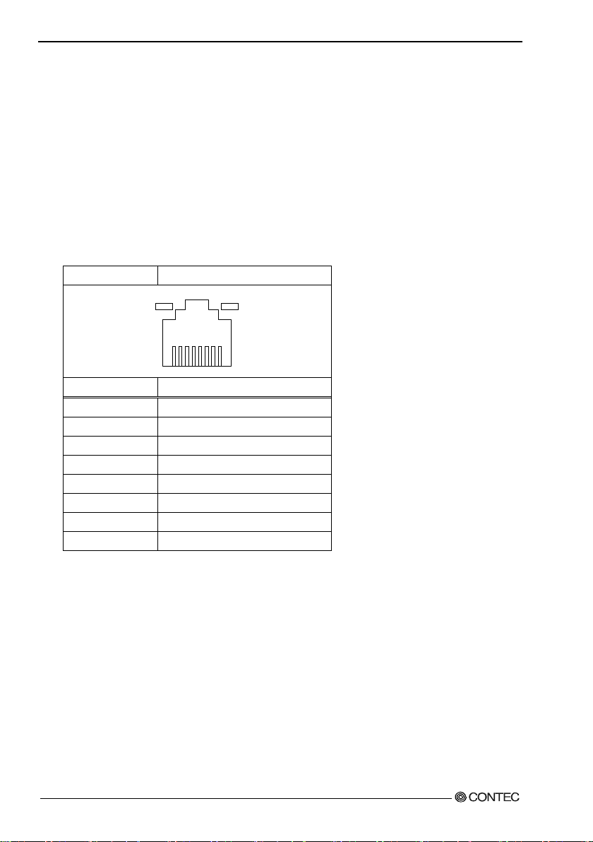
5.Each co m ponent functi on
Connec tor type
RJ-45
Pin No
Signal 1 TD+ 2 TD-
3
RD+
4
GND 5 GND 6 RD-
7
GND
8
GND
◆Ethernet
The VP C-3000 is equipped with two channels for Ethernet.
・Network type : 100BASE-TX/1000BASE-T
・Transmission speed : 100M/1000Mbps
・Max.network path length : 100m/segment
・Controller : Intel(R) I218-LM GbE Ethernet Controller(LAN1)
Intel(R) I210-AT GbE Ethernet Controller (LAN2)
* 1000Mbps operation requires a cab le of category 5E or greater.
Table 5.9 Ethernet connector
LINK/ACT 100/1 000M
8
LEDs for displa y of netwo r k sta tuses
LINK/ACT LED :(Green) Lighting at the normal connection.
(Green) Blinking at the data transmission and receive.
100/1000M LED :(Green) Lighting at the 100M ope ration.
(Orange) Lighting at the 1000M opera ti on.
1
78 User’s Manual
Page 86

5.Each co m ponent functi on
JDIO1
JDIO2
Pin No
Signal
Pin No
Signal
1
I0 7 O0 2 I1 8 O1
3
I2
9
O2 (Conne cted pro hibiti o n)
4
I3
10
O3 (Connected prohibition)
5
PWRON
11
COMPO
6
RST
12
COMPI
1
7
6
◆Digital I/O interface
This interface controls digital I/O with two rows of six pins (JDIO1, JDIO2).
Among t h e ei g ht D IO pi n s , t w o ou tput pi ns (02, 03) are used for the user LED on the front.
The d igital I/O in terface is internally insulated.
Table 5.10 Digital I/O connector
JDIO2 JDIO1
1) I0~I3 (JDIO1 Pin No. 1~4)
Input signal : You can input Input0, Input1, Input2, and Input3.
2) O0~O3 (JDIO2 Pin No. 7~10)
Output s ignal : You can o utput Onput0, Onput1, On put2, and Onput3.
※You can not use Output2,3 because they are used for the user LED on the front.
3) PWRON,RST (JDIO1 Pin No.5,6)
Short-circuiting PWRON and GN D or RST and GND tr iggers the sa me operation as pus hing the
Power butt on or Res et butto n on the fr ont .
※However, the power-supply from the outside is necessar y.
4) COMPO,COMPI (JDIO2 Pin No11,12)
These are used fo r the power-supply from the outside. COMPO is GND and COMPI is VCC.
User’s Manual
79
Page 87

5.Each co m ponent functi on
Example of customer construction circuit
inetrnal
external
internal
external
Prepare DC12V ~24V
power
Example of customer construction circuit
Prepare DC12V ~24V
power
Inter na l equ i vale nt circuit chart of the remote power and the remote reset
-supply separately
Figure5.3 External I/O connecti on internal equivalent circuit diagram
External I/O connection VPC-2000 internal equivalent circuit diagram
-supply separately
Figure5.4 External I/O connecti on internal equivalent circuit diagram
80 User’s Manual
Page 88

5.Each co m ponent functi on
Pin No
Signal name
Blue
Line-In
Green
Line-Out
Pink
Mic-In
◆Audio interface
The audio interface is provided.
Table 5.11 Audio connector
Bule
Green
Pink
User’s Manual
81
Page 89
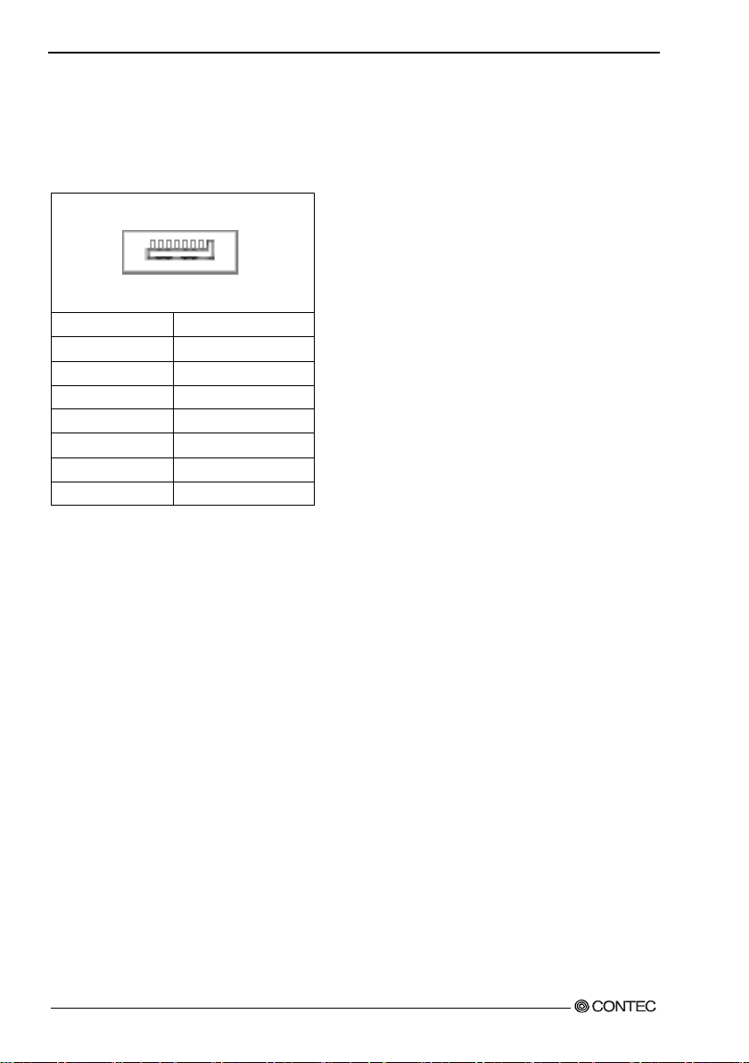
5.Each co m ponent functi on
Pin No
Signal
1
GND 2 TX+ 3 TX- 4 GND 5 RX- 6 RX+ 7 GND
◆Seria l ATA interface
Six serial ATA port interfaces are provided.
Table 5.12
Serial ATA connector
7 1
82 User’s Manual
Page 90

OEM
6.Software Utility
6.Softwar e Utility
This chapter describes the driver DVD included with the VPC-3000 series. This d ri ver DVD includes
drivers and software necessary for the VPC-3000 series.
This dr iver DVD does not provide Autorun functionality. Install drivers and software manually through
Windows Explorer after inserting this driver DVD into the CD/DVD-ROM drive.
The contents of the driver DVD are subject to change without prior notice.
Pre-installed models ar e not accompanied by a driver DVD. A driver DVD is included with models that
come without an OS.
Driver DVD
The directory structure of the driver DVD is shown below.
In the recovery medi a, the following directo ry doesn't exist.
Please download each driver and utility fr om our homepage for the pre-install mod el.
└─Drivers ← Pre-installed models have these installed in the OS.
├─Step1 Chipset
├─Step2 Intel ME
├─Step3 USB3.0
├─Step4 Lan
├─Step5 Graphic
├─Ste p6 Audio
└─Step7 Raid
・Drivers : Ver sions of the installation files for above drivers are included separately for each
operating
systems.
User’s Manual
83
Page 91

6.Software Util it y
Various drivers
Install drivers i n the "Drivers" folder according to the diffe rent steps. Since the drivers to install depe nd
on wh i c h O S is used, install the dri vers appropriate for yo ur OS.
84 User’s Manual
Page 92

7.Software RAID setup
Intel(R) Rapid Storage Technology –Option ROM - 12.5.0.1815
C
AUT
ION
CAUTION
7.Software RAID setup
. This cha pter de s cr i bes so ft ware mirr or ing (RA I D 1 ) s etu p. We onl y su p port mi rr oring.
CONTEC on ly supports RAID1. Oper ations of al l ot her RAID confi gurations (RAID0, RAI D 5, RAID10)
are not supported.
Be aware that functions not supported are outside the scope of the warr a nty.
If RAID settings ar e changed, all data on the hard disks will be erased.
Back up necessary data in advance.
Starting the setup s cree n
Before starting the RAID utility, set the AHCI device to R AID in the BIOS setup described
in Chapter 4. Press the <CTRL> an d <I> keys on the fo llowing screen to start the RAID utility.
After a few seconds, the RAID utility can be started.
Copyright(C) 2003-09 Intel Corporation. All Right Reserved.
RAID Volumes:
ID Name Level Strip Size Status Bootable
Physical Disks:
Port Drive Model Serial # Size Type/Status(Vol ID)
* *********** **** * ** * ***** ***GB Non-RAID Disk
* *********** ************* ***GB Non-RAID Disk
Press <CTRL-I> to enter Configuration Uti lity..
Figure 7.1 Setup screen
If the AHCI(or IDE) device is not set to RAID in the BIOS setup, the above screen will not appear .
The above screen does not appear on displays other than that specified for Primary IGFX Boot
Display on the Gra phic s Co n fi guration sett ing screen.
User’s Manual
85
Page 93
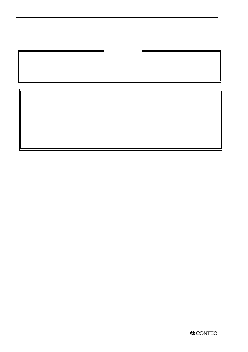
7.Software RAID setup
[ MAIN MENU ]
[ DISK/VOLUME INFORMATION ]
MAIN Window
When you start the RA ID utility, the main window appears.
1. Cre ate RAID Volume 4. Recovery Vol ume Options
2. Delete RAID Volume 5. Acceleration Option
3. Reset Disks to Non-RAID 6. Exit
RAID Volume s:
None defined.
Physical Dev ices:
ID Drive Model Serial # Size Type/Status(Vol ID)
* *********** ************* ***GB Non-RAI D Di sk
* *********** ************* ***GB Non-RAID Disk
[↑↓]-Select [ESC]-Exit [ENTER]-Select M enu
Figure 7.2 MAIN Window
1. The cursor keys <↑>, <↓>, <→>, <←> allow you to navigate through menu items and the <Enter>
key allow s you to choose amo ng them.
(You can also select items by entering menu numbers 1 to 4 with the keyboard.)
2. You are prompted to confirm that you are saving the curren t settings. Press the <Y> key to save them
and press the <N> or <ESC> key to exit the RAID utility without saving them.
- RAID Volume : Displays the type, volume, and status of the crea ted RAID drive.
- Physic a l Disks : Displays hard disks which will be the target of the RAID drive.
Create RAID Volume : A RAI D dr ive ca n be created . T h e t y pe and capacity of the created RAI D
drive can be s et whe n it i s creat e d .
Delete RAI D V ol ume : An ex i s t ing R AID dr ive can be delete d. If delet ed , da t a wi l l be lost.
- Exit : Exit RAID utility.
86 User’s Manual
Page 94

7.Software RAID setup
[ CREATE VOLUME MENU ]
[ HELP ]
Create RAID Drive (Mirroring)
Figure 7.3 RAID dri ve create screen
1. Selec t “C reate RAI D Vol um e” by pressing the <Ente r> key or the <1> key in the Main w indow.
2. The <TAB> key and the <Enter> key allow you to navigate through items.
3. Select “RAID1(Mirror)” by pressing the <> and <> keys for the “RAID Level” setting and press
the <TAB> key or the <Enter> key to confirm the setting.
4. After you have finished configur ing the settings, select the “Cre ate V olume” item, and then press the
<Enter> key.
5. When you a re prompted to confirm that you are creat ing the RAID d rive, press the <Y> key.
6. The RAID drive will be created in the “RAID Volume” item in the Main window. The
“Type/Status(Vol ID)” of the HDD will indicate “Membe r Dis k”.Press the <> and <> keys to
select “Exit” in the Main window, and then confirm your choice by pressing the <Enter> key or the
<6> key.
7. When you are pr ompted to confirm that you are sa ving the cur rent settings, press the <Y > key to exit
the RAID utility.
User’s Manual
Nam e: Vol ume1
RAID Level: RAID1(Mirror)
Disks: Select D isks
Strip Size: N/A
Capacity: ***GB
Sync: N/A
Create Volume
Choose the RAID level:
RAID 0: Stripes data (performance).
RAID 1: Mirror data (redundancy).
Recovery: Copies data between a mas ter and a recovery disk.
[↑↓]Change [TAB]-Next [ESC]-Previous Menu [ENTER]-Select
87
Page 95

7.Software RAID setup
CA
U
TI
ON
Mirr or ing r equir e s the creation of a RAID dr ive be f ore install ing the OS. I f a RA I D dr ive is created
after installing the OS, data will be lost and the OS will be unable to boot.
Our support is limited to mirroring. Creating a RAID dr ive other than a mirroring RAID is up to the
custo m er. We assume no res p onsibi li t y f or damage ca used b y do i n g s o.
88 User’s Manual
Page 96

7.Software RAID setup
CAUTION
[ DELETE VOLUME MENU ]
[ HELP ]
Delete RAID drive (Mirro ring)
Name Level Drives Capacity Status Bootable
***** RAID1(Mirror) 2 ***GB ***** Yes
Deleting a volum e wil l re set the disks to n o n -RAID.
WARNING: ALL DISK DATA WILL BE DELETE.
(This does not apply to Re c overy volumes)
[↑↓]Select [ESC]-Previous Menu [DEL]-Delete Volu me
Figure 7.4 RAID dri ve delete screen
1. Selec t “D elete RAI D Vol um e” by pressing the <Ente r> key or the <2> key in the Main w indow.
When all mirroring-configured RAID drives are displayed, press the <↑> and <↓> keys to move to
the RAID drive to be deleted and press the <DEL> key.
2. When you are pro mp t e d to co nfirm tha t you ar e d eleting t he selecte d RAID dri ve , press th e <Y > ke y.
3. The RAI D dr ive will be deleted from “RAID Volume” in the M ain window. Its “Type/Status” will
indicate “Non-RAID Disk”.
4. Press the <↑> and <↓> keys to select “Exit” in the Main window, and confirm your choice by
pressi ng the <Enter> key or the <4> key.
5. When you are pro mp t e d to confirm that yo u a re saving the current se ttings, pres s the <Y> key to exit
the RAID utility.
When an existing RAI D drive is delet ed, data may be lost. Back up the data on a RAID d ri ve before
deletin g it if the data is imp ortant.
User’s Manual
89
Page 97
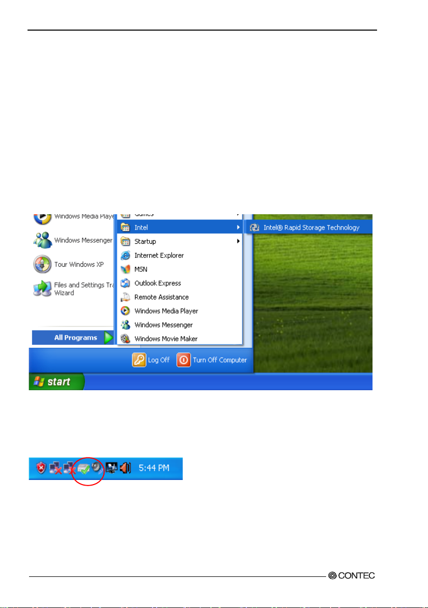
7.Software RAID setup
Software RAI D monitoring tool (Raipd Strage Technology)
Matrix Storage Console allows you to monitor the information and status of an existing RAID drive or
HDDs comprising a RA ID drive. Furthermore, as necess ary, it allows creating, deleting and reconfiguring
of RAID drives.
◆Rapid Strage Technology Install
When the system is recovered using the bundled recovery CD-ROM, Ra pid Storage Techonology
will be installed b y default .
◆Starting the Rapid storage technology
After installing Rapid Storage Technology, you can l a unch it from “Start Menu” - “Programs”.
Figure 7.5 Rapid Strage Techonol ogy Launch
When the contents of Rapid storage technology are updated or activities are in progress internally, an icon
is display in the Task Manager. You can also launch it by clicking t h e ic on. Be aware that the ico n is not
always displ ayed in the Task Bar.
Figure 7.6 Rapid Strage Techonol ogy icon
90 User’s Manual
Page 98

7.Software RAID setup
◆Exiting the Rapid storage technology
You can exit Rapid storage technology by clicking “×” on the upper righ t cor ner of the window.
Figure 7.7 Exiting the Rapid Strage techonology
User’s Manual
91
Page 99
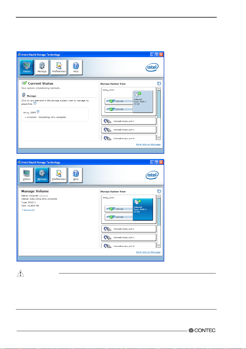
7.Software RAID setup
CAUTION
◆Making of mirroring synchronize
Data on mi rrore d dr ives is c o mpa red, a nd i f a di ff e r e n c e is f ound, da t a on th e dr ives wil l b e co pied
between HDDs and data on the mirrored drives w ill be automatically unified.
Figure 7.8 Making of mirr oring sync hronize
Synchronization by Rapid storage technology cannot be suspended while it is in progress. In
addition, you should not turn off the power to the PC while synchronization is in progress. Doing so
will cause data loss and data error.
If a HDD to be mirroring-configured is not a “Member disk”, you have to set it to be a mirrored
drive using the RAID utility or Rapid storage technology.
92 User’s Manual
Page 100

7.Software RAID setup
CAUTION
◆Cre ate RAID d rive (Mirroring )
You ca n create a mir r orin g RAID drive from Rapid storage technology.
1. Sele ct “Cr ea te Volume” on th e Arr ay drive.
Figure 7.9 Create RAID drive (Mirroring)
2. Check “Real-time data protection (RAID1)” and se lect “Next”.
User’s Manual
When the RAID drive is m ade by the total content of HDD 2 piece connected, “Make” item is not
displa y e d. RAID dri ves which can created are up two drives in total.
93
 Loading...