

Page 1

FA-PC VPC Series
VPC-2000
User’s Manual
CONTEC CO.,LTD.
Page 2

Page 3

Table of contents
Table of contents ................................................................................................................................i
CHAPTER1 INTRODUCTION 1
About the Product ...............................................................................................................................1
◆Basic performance....................................................................................................................1
◆Commodity model........................................................................................................................2
◆Supported OS..............................................................................................................................2
Customer support .................................................................................................................................3
◆Web Site ......................................................................................................................................3
◆Limited One-Year Warranty ....................................................................................................3
◆How to Obtain Service............................................................................................................ 4
◆Liability ....................................................................................................................................4
Safety precaution ...............................................................................................................................4
◆Safety infomation....................................................................................................................4
◆Handling precautions.............................................................................................................. 5
CHAPTER2 ABOUT THE PRODUCT 7
Specification .......................................................................................................................................7
Physical dimensions...........................................................................................................................9
Motherboard Block chart.................................................................................................................12
Keyboard specification...................................................................................................................13
Mouse specification.........................................................................................................................14
CHAPTER3 HARDWARE SETUP 15
Before Using the VPC-2000 for the First Time.......................................................................15
Hardware setup ...................................................................................................................................16
◆Removing the top cover and drive bay............................................................................16
◆Locations and settings of internal connectors and jumpers .................................19
◆Jumper setting........................................................................................................................21
◆Mother board internal connector......................................................................................24
◆Attaching the hard disk......................................................................................................30
◆Replacing the optical drive..............................................................................................33
◆Attaching the expansion memory........................................................................................35
◆Attaching the extension board..........................................................................................36
◆Replacing the front fan unit............................................................................................37
◆Replacing the dustproof filter........................................................................................38
◆Replacing the CMOS battery................................................................................................39
◆Option: Attaching the horizontal installation bracket .........................................40
◆Option: Removing the horizontal installation bracket ...........................................40
◆FG connection..........................................................................................................................41
User’s Manual
i
Page 4

◆Installation requirements ..................................................................................................42
◆Removing the DIO pins ..........................................................................................................44
◆Option: Attaching and removing the mirror card........................................................45
CHAPTER4 BIOS SETUP 47
Starting the setup screen .............................................................................................................47
Key operation......................................................................................................................................48
Main window..........................................................................................................................................49
◆Setting of the date and time ............................................................................................49
Setting of the start password .....................................................................................................50
Release of setted the password ...................................................................................................51
Changing to the device boot order .............................................................................................52
Selecting to the IDE device .........................................................................................................52
Setting for the power on (AT power operation) by the AC power-supply turning on 53
Factory default setting..................................................................................................................54
◆MAIN.............................................................................................................................................55
◆Advanced.....................................................................................................................................55
◆Boot.............................................................................................................................................59
◆Security.....................................................................................................................................60
◆Chipset.......................................................................................................................................60
◆Exit.............................................................................................................................................62
CHAPTER5 EACH COMPONENT FUNCTION 63
Component name....................................................................................................................................63
◆VPC-2000 front view ..............................................................................................................63
◆VPC-2000 rear view ................................................................................................................64
Component Function............................................................................................................................65
◆Keyboard interface ................................................................................................................65
◆Mouse interface.......................................................................................................................65
◆Serial port interface ..........................................................................................................66
◆CRT interface...........................................................................................................................67
◆DVI interface...........................................................................................................................68
◆Printer port interface ........................................................................................................69
◆Reset switch.............................................................................................................................70
◆Power switch.............................................................................................................................70
◆USB port.....................................................................................................................................70
◆Ethernet.....................................................................................................................................71
◆Digital I/O interface ..........................................................................................................72
◆Audio interface.......................................................................................................................74
◆Floppy disk interface ..........................................................................................................75
◆Serial ATA interface ............................................................................................................76
ii User’s Manual
Page 5

CHAPTER6 SOFTWARE UTIRITY 77
Driver DVD ........................................................................................................................................... 77
Various drivers .................................................................................................................................78
IO-Lib(NT) ........................................................................................................................................... 78
RAS tool ...............................................................................................................................................84
◆Watch-Dog Timer (WDT) Setting..........................................................................................88
◆Hardware monitor....................................................................................................................89
◆General purpose input..........................................................................................................92
◆General purpose output........................................................................................................93
Hardware RAID monitoring tool .....................................................................................................94
◆Setup ..........................................................................................................................................94
◆Specification..........................................................................................................................96
◆Starting the monitoring tool............................................................................................97
◆Exit the monitoring tool ....................................................................................................97
◆Status ........................................................................................................................................98
◆Version ......................................................................................................................................98
◆Automatic start......................................................................................................................99
◆Command option......................................................................................................................100
◆Log functional......................................................................................................................101
◆API library Specification ................................................................................................103
CHAPTER7 SOFTWARE RAID SETUP 107
Starting the setup screen...........................................................................................................107
Main Window .......................................................................................................................................108
Create RAID drive (Mirroring) ...................................................................................................109
Delete RAID drive (Mirroring) ...................................................................................................111
Software RAID monitoring tool(Rapid storage technology) ..............................................112
◆Rapid storage technology Install..................................................................................112
◆Starting the Rapid storage technology........................................................................112
◆Exiting the Rapid storage technology..........................................................................113
◆Making of mirroring synchronize....................................................................................114
◆Create RAID drive (Mirroring)........................................................................................115
◆Delete RAID drive (Mirroring)........................................................................................118
◆For the error........................................................................................................................119
◆Confirming the error log ..................................................................................................120
RAID setup when replacing the HDD........................................................................................... 121
RAID setup when replacing the HDD........................................................................................... 121
CHAPTER8 HARDWARE RAID SETUP 123
Functional specification.............................................................................................................123
◆Locations and settings of switches and connectors ...............................................123
User’s Manual
iii
Page 6

Introduction
◆Switch setting.......................................................................................................................124
◆Internal LED status ............................................................................................................125
Hardware RAID setup........................................................................................................................126
◆Operation flow.......................................................................................................................126
◆For the error.........................................................................................................................128
◆RAID setup when replacing the HDD ................................................................................129
◆Hot-swap...................................................................................................................................130
OS recovery setting........................................................................................................................131
FAQ・Troubleshooting......................................................................................................................132
◆FAQ.............................................................................................................................................132
◆Troubleshooting.....................................................................................................................133
CHAPTER9 LIST OF OPTIONS 137
iv User’s Manual
Page 7
Chapter1 Introduction
Chapter1 Introduction
About the Product
The VPC-2000 series is a BTO industrial PC that is equipped with either an Intel® Core i7 860 (2.8GHz),
Core i5 660 (3.33GHz), or Pentium G6950 (2.8GHz). The Intel® Q57 chipset with DDR3 memory (2GB or
4GB) provides a system with extreme computing and graphics performance. These products feature a
variety of interfaces, including 8 USB ports (Front: 2, Rear: 6), 2 1000BASE-T ports, 1 RS-232c
port and 1 parallel port. These units are ideal for a wide range of embedded applications, such
as control devices and information terminals based on general-purpose PC OSes. This series provides
carefree use under harsh working conditions such as FA, achieving superb environmental resistance
and a long-term stable supply due to careful selection of parts such as embedded CPUs and chipsets.
This product is available in the following 1 model.
<Base Model>
VPC-2000 Black
<Standard Model>
Model name CPU Memory HDD Optics system drive OS
VPC-2000-16200B None
VPC-2000-16222B
Intel Pentium G6950
VPC-2000-36222B
Windows XP
Professional
(Japanese)
VPC-2000-37225B
Intel Core i5 660
VPC-2000-47225B Intel Core i7 860
Memory
2GB
SATA
160GB
DVD Multi drive
Windows 7 Professional
(Japanese)
◆Basic performance
・ Intel® Core i7 is installed (※Core i7 Model)
Embedding a high-performance CPU, the VPC-2000 series has achieved lower prices.
・ Intel® Q57 Chipset is adopted
Employing an embedded-style chipset, the VPC-2000 series has achieved a long-term stable supply.
・ It Corresponds to mirroring(RAID1)
The construction of the mirroring becomes possible and the system can be made tedious.
[Software RAID]
It is possible to have software mirroring configuration by employing ICH10DO at the southbridge.
However, it can not hot-swap.
[Hardware RAID]
Because option : Mirror card is choiced, it is possible to have Hardware mirroring configurations.
This can hot-swap.
・ Suitable chassis for embedded applications
Taking advantage of our rich experience, the VPC-2000 series is designed with optimization for
heat dissipation, operating vibration dampening and consideration for scalability.
・ Supports high-speed high-capacity memory
The VPC-2000 series supports DDR3 SDRAM DIMM modules (2GB or 4GB) designed for high-speed
transfer speed, flexibly addressing memory-consuming applications such as image processing.
User’s Manual
1
Page 8

Chapter1 Introduction
◆Commodity model
VPC-2000 model rule
・Model name
・Type name
S3601B12000XX XX
①②③④⑤⑥⑦⑧⑨⑩⑪⑫⑬⑭⑮
① Power-supply ⑧ RAID (Mirroring)
S:
Standard specification (Made in foreign countries)
0:
None
R:
Software RAID
②
CPU H :
Hardware RAID
1 : Pentium G6950
3 : Core i5 660
⑨ Operating system
4 : Core i7 860 0 : None
2 : Windows XP Professional (JPN)
③Memory
4 : Windows 7 Professional (JPN)
6 : PC3-10600 DDR3 2GB(2GB×1) B : Windows XP Pfofessional (ENU/JPN/CHS)
7 : PC3-10600 DDR3 4GB(2GB×2) D : Windows 7 Professional (ENU)
④VGA ⑩Keyboard
0:
None
0 : None
1:
AD-8001(AMD M72)
1 : Japanese 109 keyboard (PS/2)
A : English 104 keyboard (PS/2)
⑤ Hard disk (SATA1)
0:None ⑪ Mouse
1 : 160GB 3.5inch HDD(SATA) 0 : None
B : 2TB 3.5inch HDD(SATA) 1 : Mouse (PS/2)
⑥ Hard disk (SATA2) ⑫ Onsite Maintenance Service
0:None 0 : None
1 : 160GB 3.5inch HDD(SATA) 2 : Onsite maintenance service of two ye
B : 2TB 3.5inch HDD(SATA) 3 : Onsite maintenance service of three
⑦ Optics system drive ⑬ X:Reserve
0:None ⑭ X:Reserve
1:
DVD-Multi drive ⑮ X:Reserve
VPC-2000
◆Supported OS
・ Windows XP Professional
・ Windows 7 Professional
2 User’s Manual
Page 9

Chapter1 Introduction
Customer support
CONTEC provides the following support services for you to use CONTEC products more
efficiently and
comfortably.
◆Web Site
Japanese http://www.contec.co.jp/
English http://www.contec.com/
Chinese http://www.contec.com.cn/
■Latest product information
CONTEC provides up-to-date information on products.
CONTEC also provides product manuals and various technical documents in the PDF.
■Note! For product information
Contact your retailer if you have any technical question about a CONTEC product or need
its price,
delivery time, or estimate information.
◆Limited One-Year Warranty
CONTEC products are warranted by CONTEC CO., LTD. to be free from defects in material
and
workmanship for up to one year from the date of purchase by the original purchaser.
Repair will be free of charge only when this device is returned freight prepaid with
a copy of the original
invoice and a Return Merchandise Authorization to the distributor or the CONTEC group
office, from
which it was purchased.
This warranty is not applicable for scratches or normal wear, but only for the electronic
circuitry and
original products. The warranty is not applicable if the device has been tampered with
or damaged
through abuse, mistreatment, neglect, or unreasonable use, or if the original invoice
is not included, in
which case repairs will be considered beyond the warranty policy.
User’s Manual
3
Page 10
Chapter1 Introduction
◆How to Obtain Service
For replacement or repair, return the device freight prepaid, with a copy of the original
invoice. Please
obtain a Return Merchandise Authorization number (RMA) from the CONTEC group office where
you
purchased before returning any product.
* No product will be accepted by CONTEC group without the RMA number.
◆Liability
The obligation of the warrantor is solely to repair or replace the product. In no event
will the warrantor
be liable for any incidental or consequential damages due to such defect or consequences
that arise from
inexperienced usage, misuse, or malfunction of this device.
Safety precaution
Understand the following definitions and precautions to use the product safely.
◆Safety infomation
This document provides safety information using the following symbols to prevent
accidents resulting in
injury or death and the destruction of equipment and resources. Understand the meanings
of these labels
to operate the equipment safely.
DANGER indicates an imminently hazardous situation which, if not
avoided, will
result in death or serious injury.
WARNING indicates a potentially hazardous situation which, if not
avoided, could result in death or serious injury.
CAUTION indicates a potentially hazardous situation which, if not
avoided, may
result in minor or moderate injury or in property damage.
4 User’s Manual
Page 11

Chapter1 Introduction
◆Handling precautions
CAUTION indicates a potentially hazardous situation which, if not
avoided, may result in minor or moderate injury or in property
damage.
・ Do not use or store the product in a location exposed to extremely high or low temperature
or susceptible to rapid temperature changes.
Example ・Exposure to direct sun
・In the vicinity of a heat source
・ Do not use the product in extremely humid or dusty locations. It is extremely dangerous to
use the product with its interior penetrated by water or any other fluid or conductive dust.
If the product must be used in such an environment, install it on a dust-proof control panel,
for example.
・ Avoid using or storing the device in locations subject to shock or vibration.
・ Do not use the product in the vicinity of devices that generate strong magnetic force or noise.
Such devices will cause this device to malfunction.
・ Do not use or store the product in the presence of chemicals.
・ To clean, wipe it gently with a soft cloth dampened with either water or mild detergent.
Do not use chemicals or a volatile solvent, such as benzene or thinner, to prevent pealing,
discoloration of the paint, or deterioration of resin.
・ As continuous operation of the equipment may shorten the life of the hard disk drive, use it
in stand-by mode.
・ Be sure to unplug the power cable from a wall outlet before plugging or unplugging a extension
board or any connector.
・ CONTEC reserves the right to refuse to service a product modified by the user.
・ In the event of failure or abnormality (foul smells or excessive heat generation), unplug the
power cord immediately and contact your retailer.
・ Use an AC cable suitable for your supply voltage and outlet/plug. (The supplied cable is for
125V AC.
・ The hard disk must be replaced when the power of the main unit is off. It is not hot-swappable.
Removing the hard disk during operation may damage the system.
(However, hardware raid is excluded.)
・ Component Life:
(1)Power・・・・・・・・・During continuous operation at 40℃, the assumed life is about four years
(vertical installation). However, it may be shortened due to operating
temperature (high temperatures).
(2)Battery・・・・・・・The internal calendar clock and CMOS RAM are backed by a Lithium primary
battery. The backup time at a temperature of 25°C with the power disconnected
is 10 years or more.
(3)Chassis FAN・・・During operation at 40℃, the assumed life is about six years.
However, it may be shortened due to operating temperature.
* Replacement of expendables is handled as a repair (there will be a charge).
・ To connect with peripherals, use a grounded, shielded cable.
・ Do not use a UPS (uninterruptible power supply) with square-wave output, as connecting it
may damage the system.
・ Risk of explosion if battery is replaced by an incorrect type. Dispose of used batteries
according to the instructions.
・ Abandon a used battery appropriately according to the instruction of the municipality.
User’s Manual
5
Page 12
Chapter1 Introduction
VCCI Class A and FCC PART 15 Class A Notice
FCC PART 15 Class A Notice
This equipment has been tested and found to comply with the limits for a Class A digital device,
pursuant to part 15 of the FCC Rules. These limits are designed to provide reasonable protection
against harmful interference when the equipment is operated in commercial environment.
This equipment generates, uses, and can radiate radio frequency energy and, if not installed and
used in accordance with the instruction manual, may cause harmful interference to radio
communications. Operation of this equipment in a residential area is likely to cause harmful
interference at his own expense.
NOTE
Change or modifications not expressly approved the manufacturer can void the user's authority to
operate this equipment.
WARNING TO USER
VCCI Class A Notice
この装置は、クラスA情報技術装置です。この装置を家庭環境で使用すると電波妨害を引
き起こすことがあります。この場合には使用者が適切な対策を講ずるよう要求されるこ
とがあります。
VCCI-A
The object of the standard of this product becomes only a main body.
Copyright
・ N o p a r t o f t his document may be copied or reproduced in any form by any means without
prior written consent of CONTEC CO., LTD.
・ CONTEC CO., LTD. makes no commitment to update or keep current the information
contained in this document.
The information in this document is subject to change without notice.
・ All relevant issues have been considered in the preparation of this document. Should
you notice an omission or any questionable item in this document, please feel free
to notify CONTEC CO., LTD.
・ Regardless of the foregoing statement, CONTEC assumes no responsibility for any
errors that may
appear in this document or for results obtained by the user as a result of using
this product.
・ Intel, Core, Pentium are registered trademarks of Intel Corporation.
MS, Microsoft and Windows are trademarks of Microsoft Corporation.
Other brand and product names are trademarks of their respective holder. ™ and ®
mark are omitted in this document.
The latest version manual downloads from CONTEC web site.
6 User’s Manual
Page 13

Chapter2 About the product
Chapter2 About the product
Specification
Functional specification
System Specification
CPU
※1
・Intel Core i7 860
※2
---------------------------- 2.8GHz
・Intel Core i5 660 ---------------------------- 3.33GHz
・Intel Pentium G6950 --------------------------- 2.8GHz
Chipset Intel Q57 / ICH10DO
BIOS AMI BIOS
Memory
※1
2048MB(1024MB×2), 4096MB(1024MB×4)(DDR3 SDRAM DIMM)
Hard disk drive
※1
・SATAⅡ 3.5”HDD 160GB/2TB
(Software/Hardware)RAID1
・SATAⅡ 3.5”HDD 160GB/2TB ×1 or ×2
Optical drive
DVD super multi drive
Max. reading speed DVD-ROM x16, CD-ROM x48
Max. writing speed DVD+/-R x24, DVD+RW x8, DVD-RW x6,
DVD+/-R-DL x12, DVD-RAM x12, CD-R
x48, CD-RW x32
VGA Digital DVI-I 29Pin,Analog RGB(D-SUB 15Pin)
USB port Front 2 port Rear 6 port
PS/2 port 2 port (Keyboard/Mouse)
Audio
HDAC/ALC888 CODEC (7.1+2CH audio codec)
(Mike input, Line input, Line output)
Sirial
COM1,2 (RS-232C) D-SUB 9pin×2
COM3,4 (RS-232C)
※3
Parallel D-SUB 25pin×1
LAN port 10BASE-T/100BASE-TX/1000BASE-T RJ45×2
LAN Controller
Intel 82578 Gigabit Ethernet
Intel 82583V Gigabit Ethernet
Degital I/O
Front:LED output x2 Rear:output x2、Input x4
(Software API support、User application)
RAS function
WDT:1sec~255sec(Resetting operation by end)
Remote reset/Remote power on External input signal
Software RAS function
(Fan rotation、temperature、Voltage data reading)
Extended slot
PCI Express x16 (Max:176mm(L)×110mm(H))
※4
: 1slot
PCI Express x1 (Max:176mm(L)×110mm(H)) : 1slot
PCI (Max:176mm(L)×110mm(H)) : 2slot
OS
※1
・Windows XP Professional (32bit) JPN
・Windows XP Professional (32bit) [ENU/JPN/CHS]
・Windows 7 Professional (32bit) JPN
・Windows 7 Professional (32bit) ENU
Stand Wall mount
Physical dimensions(mm)
/Weight
370(W) x 470(D) x 166(H)(No protrusions)/About 14Kg
※5
Power
400W ATX Power(100-240VAC(50-60Hz) Automatic input
switch)
※1 Implement and install the options you selected.
※2 DVI-I and A-RGB of onboard can not use when you ware selected the Core i7 860.
The Graphic board is installed when the Core i7 860 is installed.
※3 The connector of the D-SUB 9 pin is output from the back of the chassis.
※4 The PCI Express ×16 slot is monopolized when the graphic board is installed on the
Core i7 860.
※5 Only the weight of the main unit. Appended goods and the packing box are excluded.
User’s Manual
7
Page 14
Chapter2 About the product
Ambient specification
Operating temperature/humidity 5~40℃/20~80%RH(No condensation)
Storage temperature/humidity -20℃~60℃/5~80%RH(No condensation)
Floating dust particles/
Corrosive gases
Not to be excessive/None
Static
electricity
resistance
Contact discharge
/±4KV(EN61000-4-2Level2,IEC1000-4-2 Level2
Atmospheric discharge
/±8KV(EN61000-4-2Level3,IEC1000-4-2 Level3
Line-noise
resistance
Line noise
AC line/2KV,Signal line/1KV
(EN61000-4-4Level3,IEC1000-4-4Level3)
Vibration
resistance
Sweep
resistance
10~57Hz/semi-amplitude 0.015m 57~150Hz/0.2G
40 min each X,Y, and Z directions (JIS C0040 compliant、
IEC68-2-6 compliant)
Impact resistance
10G, half-sine shock for 11 ms in X,Y, and Z directions
(JIS C0041 compliant, IEC68-2-27 compliant)
Standard
RoHS
EMC (EN55022、EN61000-6-2) and LVD (EN60950-1)
(注) Do not use under environmental conditions beyond normal specifications. The system may malfunction.
Option Mirror card specification
Item Specification
Number of connected drivers 2
RAID level 1
Storage capacity Max. 2TB
Cache memory size 1MB
Host interface S-ATA Max. data transfer rate:3Gbps
Drive interface S-ATA Max. data transfer rate:3Gbps
Range of power-supply voltage 4.75VDC~5.25VDC
Current consumption 1.0A
Physical dimensions (L×W) 96mm × 98.2mm
Weight 42g (max.)
Option Graphic board specification
Item Specification
GPU AMD M72-CSP128
Graphics memory 128MBH DDR3 on chip (2pcs of 16M×32bit)
Connector A-RGB/DVI-I,A-RGB,TV-out
Maximum display abuility 2048×1536 , 85Hz
Physical dimensions (L×W) 167.6mm × 68.9mm
The screen in the following display connection of power supply ON cannot be displayed.
Please turn on the power supply after connecting the display.
8
User’s Manual
Page 15
Chapter2 About the product
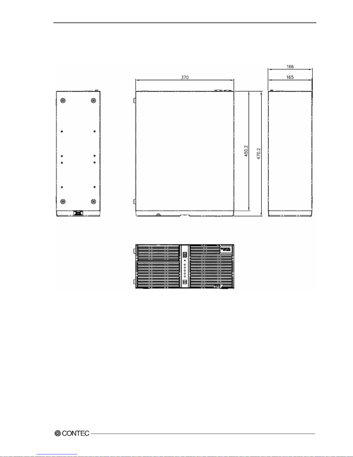
Physical dimensions
VPC-2000
[mm]
Figure 2.1 VPC-2000
User’s Manual
9
Page 16
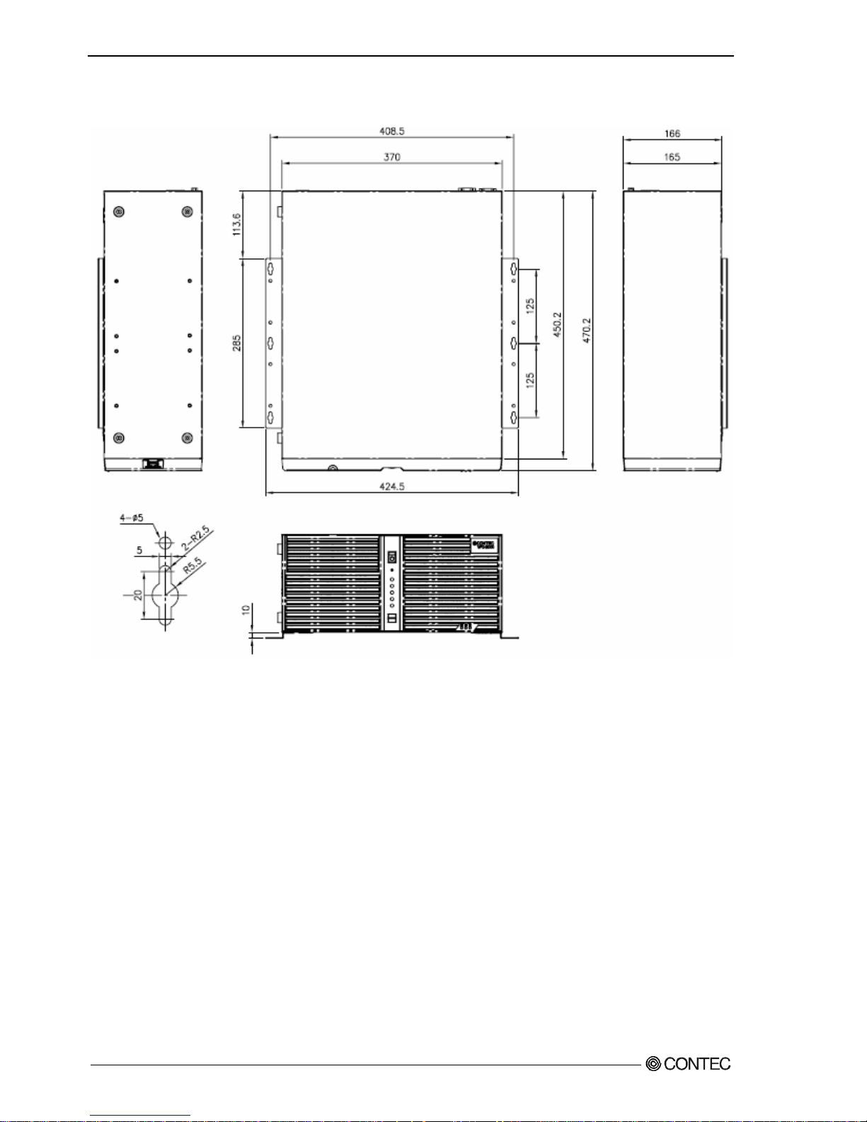
Chapter2 About the product
At installation the wall mount stand of VPC-2000 (horizontal installation)
[mm]
Figure 2.2 At installation the wall mount stand of VPC-2000 (horizontal installation)
10
User’s Manual
Page 17
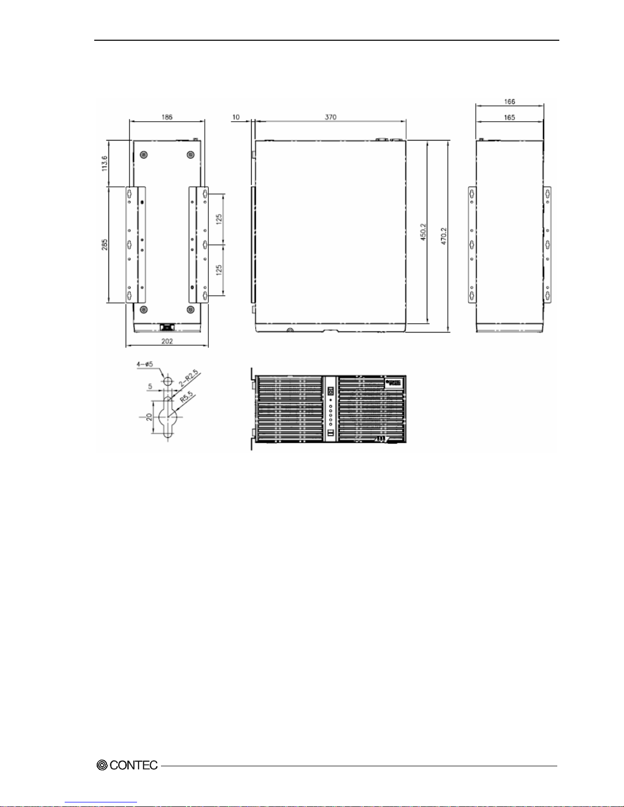
Chapter2 About the product
At installation the wall mount stand of VPC-2000 (Vertical installation)
[mm]
Figure 2.3 At installation the wall mount stand of VPC-2000 (Vertical installation)
User’s Manual
11
Page 18
Chapter2 About the product
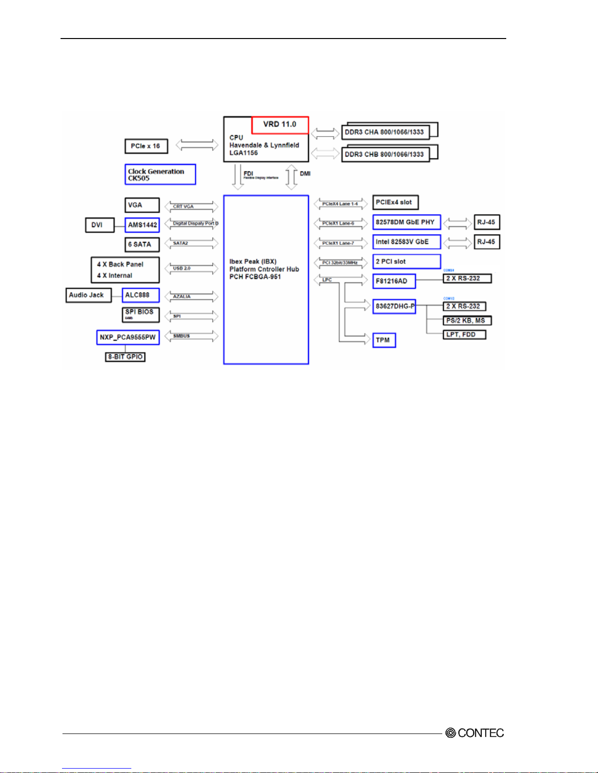
Motherboard Block chart
Figure 2.4 Motherboard Block chart
12
User’s Manual
Page 19
Chapter2 About the product
Keyboard specification
Item Specification
Key array Japanese 109 key, English 104 key
Key switch Membrane switch
Connector
USB (PS/2 Conversion connector attachment)
Length of cable(mm)
1500mm ~ 1700mm
It becomes optional of VPC-2000 in the keyboard.
Please inquire details like the specification etc. of the keyboard separately.
Moreover, the above-mentioned keyboard becomes a standard off the subject.
User’s Manual
13
Page 20
Chapter2 About the product
Mouse specification
Item Specification
Electrical
specification
Operation voltage DC +5V (±0.5V)
Interface (Connector) PS/2 (mini-DIN6pin male)
Body color White
Button 3 Piece
(One piece on the insideisa wheel.)
Number of wheels 1 Piece
Length of cable 1830mm ~ 1850mm
Physical
specification
Physical dimensions (H x D x W) 39.5mm x 117mm x 62.1mm
Tracking Resolution 460dpi
Environment
specification
Dustproof/Waterproof/Dripproof Non-correspondence
It becomes optional of VPC-2000 in the mouse.
Please inquire details like the specification etc. of the mouse separately.
Moreover, the above-mentioned mouse becomes a standard off the subject.
14
User’s Manual
Page 21

Chapter3 Hardware setup
Chapter3 Hardware setup
Before Using the VPC-2000 for the First Time
Follow the next steps to set up the VPC-2000.
STEP1 Install Hard disk, Memory (DIMM) packaging, CD-ROM, DVD Multi drive
packaging, and set Jumper switches.
By referring to the information in this chapter, set the VPC-2000.
STEP2 Connect cables.
Connect the cable of necessary external devices, such as Printer and display,
to this product using appropriate cables.
STEP3 Tuen on the Power
After venifying that you have correctly steps 1 and 2, turn on the power.
If you find any abnormality after turning on the power, turn it off and
check to see if the setup has been performed properly.
STEP4 BIOS Setup
By referring to Chapter 4, setup BIOS. This setup requires a keyboard and
a display.
※ Before using the VPC-2000, be sure to execute “Load Optimal Defaults”
to initialize the BIOS settings to their default values.
(See Chapter 4, “Exit tab”.)
If your VPC-2000 is a Windows preinstalled model, be sure to connect the keyboard
and mouse to it before turning the poer on for the first time.
User’s Manual
15
Page 22
Chapter3 Hardware setup
Hardware setup
・ Before you start, be sure that the power is turned off.
・ For internal hard disk models, ensure that physical jolts are avoided.
・ Remove only those screws that are explained. Do not move any other screw.
◆Removing the top cover and drive bay
(1) Remove the top cover.
Figure 3.1 Removing the top cover
Slide the case cover horizontally as far as it
will go, and then pull it up vertically.
The three laurette screws
16
User’s Manual
Page 23

Chapter3 Hardware setup
(2) Open the Front Cover.
Push on the latch and remove the front
front horizontally.
Figure 3.2 Opening the front cover
When you install/remove a front bezel, take sufficient care to avoid contact with the
front LED.
Contact may damage the front LED.
User’s Manual
17
Page 24
Chapter3 Hardware setup
(3) After remove four screws, the bracket for the extension board.
The four screws
Figure 3.3 Removing the extension board bracket
18
User’s Manual
Page 25
Chapter3 Hardware setup
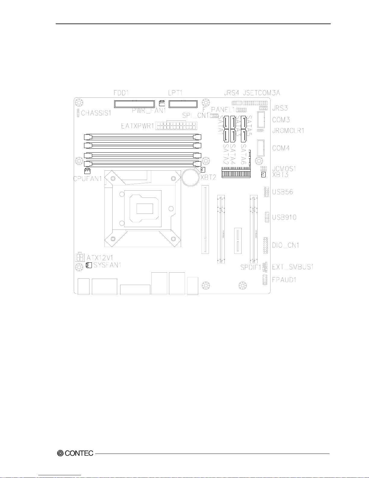
◆Locations and settings of internal connectors and jumpers
Once you have removed the case cover, the bracket for the extension board, and the drive
bay unit, you will be able to see the connectors and jumpers as illustrated below.
Figure 3.4 Locations and setting of jumpers and connectors inside the top cover
User’s Manual
19
Page 26
Chapter3 Hardware setup
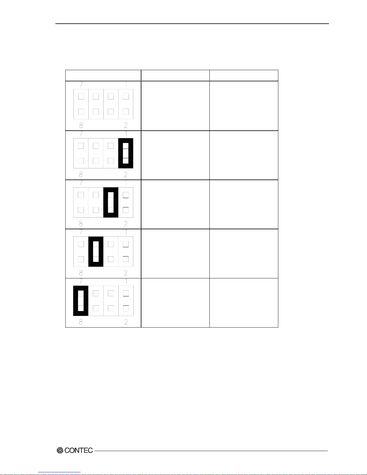
Table 3.1 Jumper setting
Name Function Factory Setting Reference page Remarks
JCOMS1 CMOS clear setting 1-2 Short P21 State usually
JMECLR1 JMECLR1 setting 1-2 Short P21 ※1
JROMCLR1 ROM clear setting 1-2 Short P22 State usually
JSETCOM3 COM3 port setting
(RS-232C)
2-4,3-5,810,9-11,14-16,
15-17,20-22,21-23 Short
P22 ※1
JRS3 COM3 Terminator Open P23 ※1
JRS4 JRS4 setting 1-2 Short P22 ※1
※1 Use the factory default settings.
Table 3.2 Connector setting
Name Function Reference
page
Name Function Reference
page
FPAUD1 ※2 - EXT_SMBUS1 ※2 -
SPDIF1 ※2 - DIO_CN1 Degital I/O connector P26,72
USB910 USB9,10 connector P27,70 USB56 USB5,6 connector P27,70
XBT2 Battery connector - XBT3 +5V dual voltage
connector
-
CON3/4 Serial connector P29,66 SATA1-6 Serial ATA 1/2/3/4/5/6
connector
P.76
F_PANEL1 Front panel connector P28 SPI_CN1 ※2 -
EATXPWR1 ATX24pin power-supply
connector
P24 LPT1 Parallel port
connector
P.69
PWR_FAN1 ※2 - FDD1 Floppy disk connector P.75
CHASSIS1 ※2 - CPU_FAN1 CPU fan connector P.25
ATX12V1 ATX 12V power-supply
connector
P24 SYS_FAN1 System fan connector P.25
※2 Please do not use it.
※3 This connector is output through wires connected to the chassis. For details, see
pages 63 and 64.
20
User’s Manual
Page 27
Chapter3 Hardware setup
◆Jumper setting
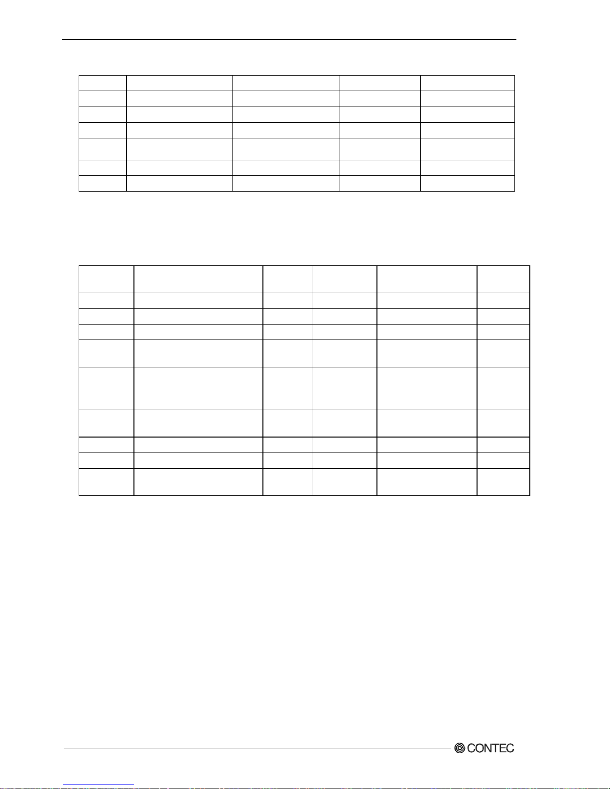
■CMOS clear setting:JCMOS1
CMOS Clear will reset the contents of the CMOS to initial BIOS values. Clearing the CMOS
will not reset the clock.
Table 3.3 CMOS clear setting
JCMOS1 Function
State usually
(Factory default setting)
CMOS clear
Always set CMOS Clear with the AC cable unplugged, and before reconnecting the power,
restore it to its normal setting.
Clearing the CMOS while the power is connected may damage the board.
■JMECLR1
Use the factory default settings.
Table 3.4 JMECLR1 setting
JMECLR1 Function
State usually
(Factory default setting)
User’s Manual
21
Page 28
Chapter3 Hardware setup
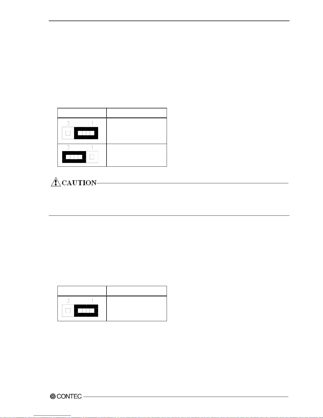
■ROM clear setting:JROMCLR1
It is possible to start by invalidating the BIOS setting because pin 2 and pin 3 are
shorted and the system is started. If the system doesn’t start, please try this setting.
Please set the CMOS again when the system starts.
Table 3.5 ROM clear setting
JROMCLR1 Function
State usually
(Factory default setting)
ROM clear
■COM3 port setting:JSETCOM3 JRS4
JSETCOM3 and JRS4 change the communication setting for com3 port. RS-232C is the factory
default setting.
Table 3.6 COM3 setting : JSETCOM3 JRS4
JSETCOM3 JRS4 Function
RS-232C
(Factory default setting)
22
User’s Manual
Page 29
Chapter3 Hardware setup
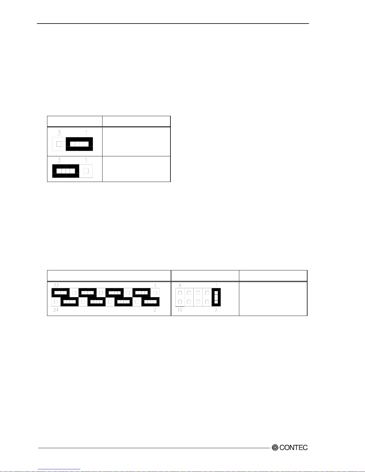
■COM3 RS-232C/485 terminator:JRS3
Table 3.7 COM3 terminator setting : JRS3
JRS3 終端抵抗 機能
None
State usually
(Factory default setting)
It is CTS
It is RTS
It is RXD
It is TXD
User’s Manual
23
Page 30
Chapter3 Hardware setup
◆Mother board internal connector
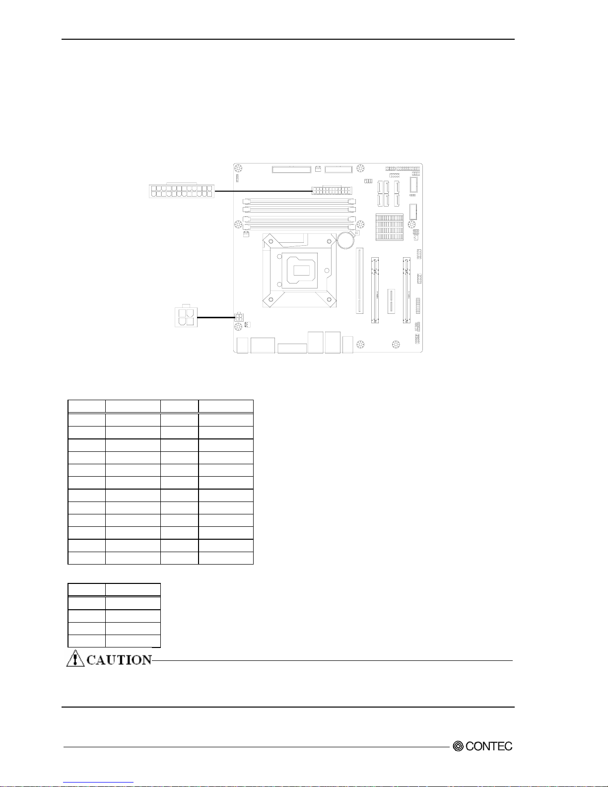
■ATX power-supply connector: EATXPWR1/ATX12V1
Connect the ATX power connector, observing the correct orientation.
24
12
1
13
EATXPWR1: ATX 24 pin connector
1
2
3
4
ATX12V1: ATX 12V power-supply connector
Figure 3.5 ATX power-supply connector
Table 3.7 EATXPWR1
PIN SIGNAL PIN SIGNAL
1 +3.3V 13 +3.3V
2 +3.3V 14 -12V
3 GND 15 GND
4 +5V 16 PS_ON
5 GND 17 GND
6 +5V 18 GND
7 GND 19 GND
8 PW_OK 20 NC
9 5V_SB 21 +5V
10 +12V 22 +5V
11 +12V 23 +5V
12 +3.3V 24 GND
Table 3.8 ATX12V1
PIN SIGNAL
1 +12V
2 GND
3 +12V
4 GND
Both EATXPWR1 and ATX12V1 are absolutely necessary power supplies for operation.
Turning on the power for only one of these may damage the system.
24
User’s Manual
Page 31

Chapter3 Hardware setup
■Fan power supply connector: CPU_FAN1/SYS_FAN1
Connectors for connecting a cooling fan.
A fan with a speed sensor can be used.
CPU_FAN1
4 1
SYS_FAN1
1
4
Figure 3.6 Fan power supply connector
Table 3.9 CPU_FAN1/SYS_FAN1
PIN SIGNAL
1 GND
2 +12V
3 SENSOR
4 CONTROL
User’s Manual
25
Page 32

Chapter3 Hardware setup
■Digital I/O connector:DIO_CN1
This connects to the digital I/O connector at the rear of the main unit.
For details, refer to Chapter 5 ”Functions of Each Unit” - “Digital I/O Interface”.
2
16
1
15
Figure 3.7 Digital I/O connector
Table 3.10 DIO_CN1
PIN SIGNAL PIN SIGNAL
1 +5V 9 I3
2 +12V 10 O3
3 I0 11 GND
4 O0 12 GND
5 I1 13 SYS_RESET
6 O1 14 GND
7 I2 15 PWRBTN_IN
8 O2 16 NC
26
User’s Manual
Page 33

Chapter3 Hardware setup
■Internal USB connector: USB5,6/USB9,10
Connectors for connecting the USB connector on the front panel of the case with an USB
extension bracket.
For the VPC-2000 series, the bracket is already connected to the USB connector on the
front panel by a special cable.
USB5,6
12
9
10
12
9
10
USB9,10
Figure 3.8 Internal USB Connector
Table 3.11 USB5,6/USB9,10
PIN SIGNAL PIN SIGNAL
1 +5V 6 USB(6or10) +Data
2 +5V 7 GND
3 USB(5or9) -Data 8 GND
4 USB(6or10) -Data 9 Key (No Pin)
5 USB(5or9) +Data 10 NC
User’s Manual
27
Page 34

Chapter3 Hardware setup
■Front panel connector: F_PANEL1
A connector for connecting the power switch, reset switch, power LED, HDD LED, etc. at
the front of the case.
For the VPC-2000 series, they are already connected on the front by a special cable.
2
1
POWER LED ER SW
HDD LED
T SW
9
10
POW
RESE
Figure 3.9 Internal front panel connector
Table 3.12 F_PANEL1
PIN SIGNAL PIN SIGNAL
HDD LED+
1 6 POWER+
2 PWLED+ 7 RESET+
3 HDD LED- 8 GND
4 GND 9 NC
5 GND 10 Key (No Pin)
28
User’s Manual
Page 35

Chapter3 Hardware setup
■COM port connector: COM3/COM4
These are connected to the COM3 and COM4 connectors at the rear of the main unit.
COM3
1
2
9
10
1
2
9
10
COM4
Figure 3.10 COM port connector
Table 3.13 COM3
RS-232C
PIN SIGNAL PIN SIGNAL
1 DCD 6 CTS
2 DSR 7 DTR
3 SIN 8 RI
4 RTS 9 GND
5 SOUT 10 Key (No Pin)
Table 3.14 COM4
PIN SIGNAL PIN SIGNAL
1 DCD 6 CTS
2 DSR 7 DTR
3 SIN 8 RI
4 RTS 9 GND
5 SOUT 10 Key (No Pin)
User’s Manual
29
Page 36

Chapter3 Hardware setup
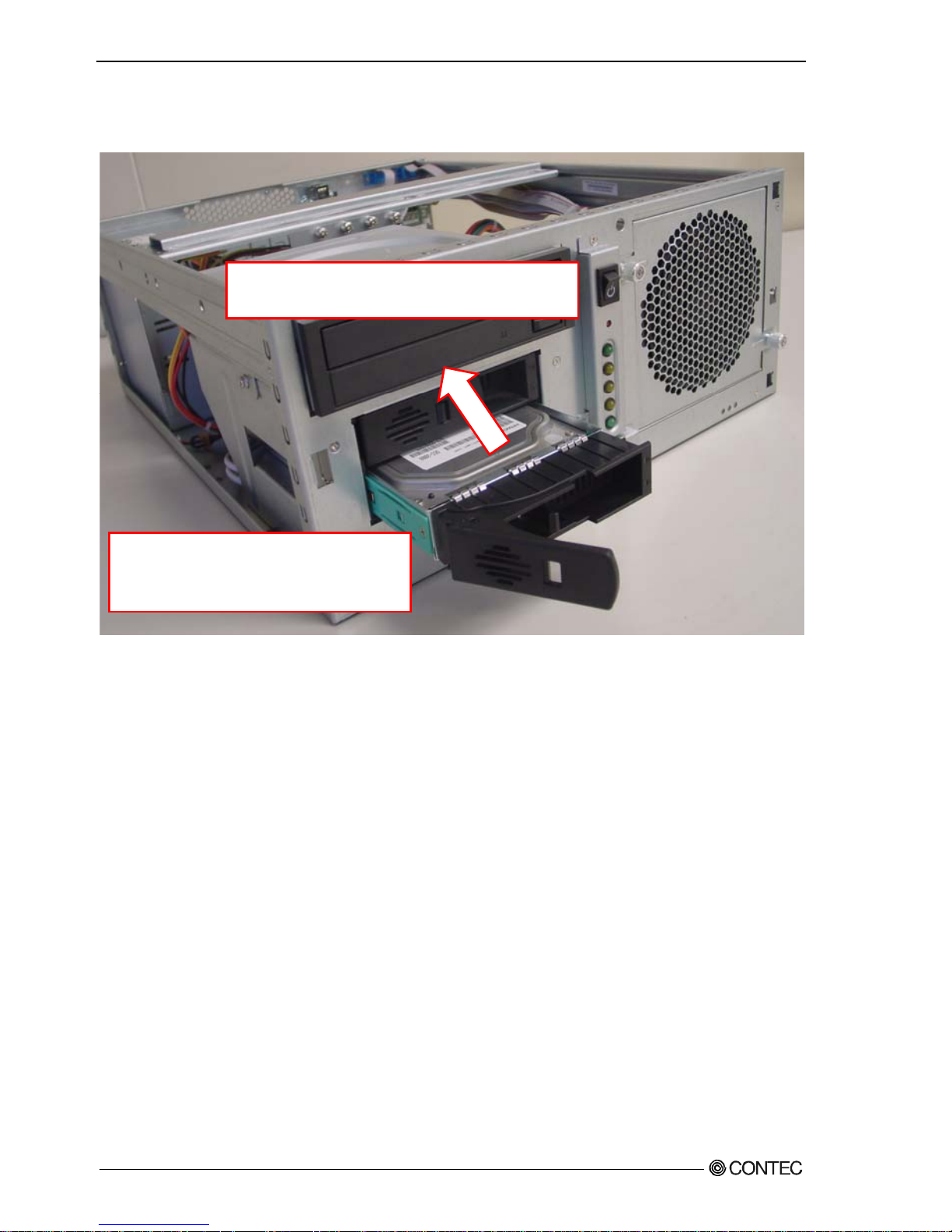
◆Attaching the hard disk
(1) Remove the removable case from the drive bay.
The knob is pulled forward while
removing the lock.
Lock
Figure 3.11 Expanding and replaying the hard disk (1)
30
User’s Manual
Page 37

Chapter3 Hardware setup
(2) Remove and replace the HDD in the removed 5-inch bay.
The four s crews
Four places of HDD in the bottom
are sto
pp
ed with the screw.
Figure 3.12 Attaching the hard disk in the drive bay (2)
User’s Manual
31
Page 38
Chapter3 Hardware setup
(3) Reverse the removal procedure and re-insert it.
The replacement HDD must be an S-ATA drive. Note the specification.
Push it in firmly until it connects to the
connector at the back.
※ If the Removable is uppe r and
lower opposite, it cannot be
connected.
Figure 3.13 Expanding and replaying the hard disk (3)
32
User’s Manual
Page 39

Chapter3 Hardware setup
◆Replacing the optical drive
(1) Remove all cables of the optical drive.
Remove all cables.
Figure 3.14 Removing all cables of the optical drive (1)
User’s Manual
33
Page 40
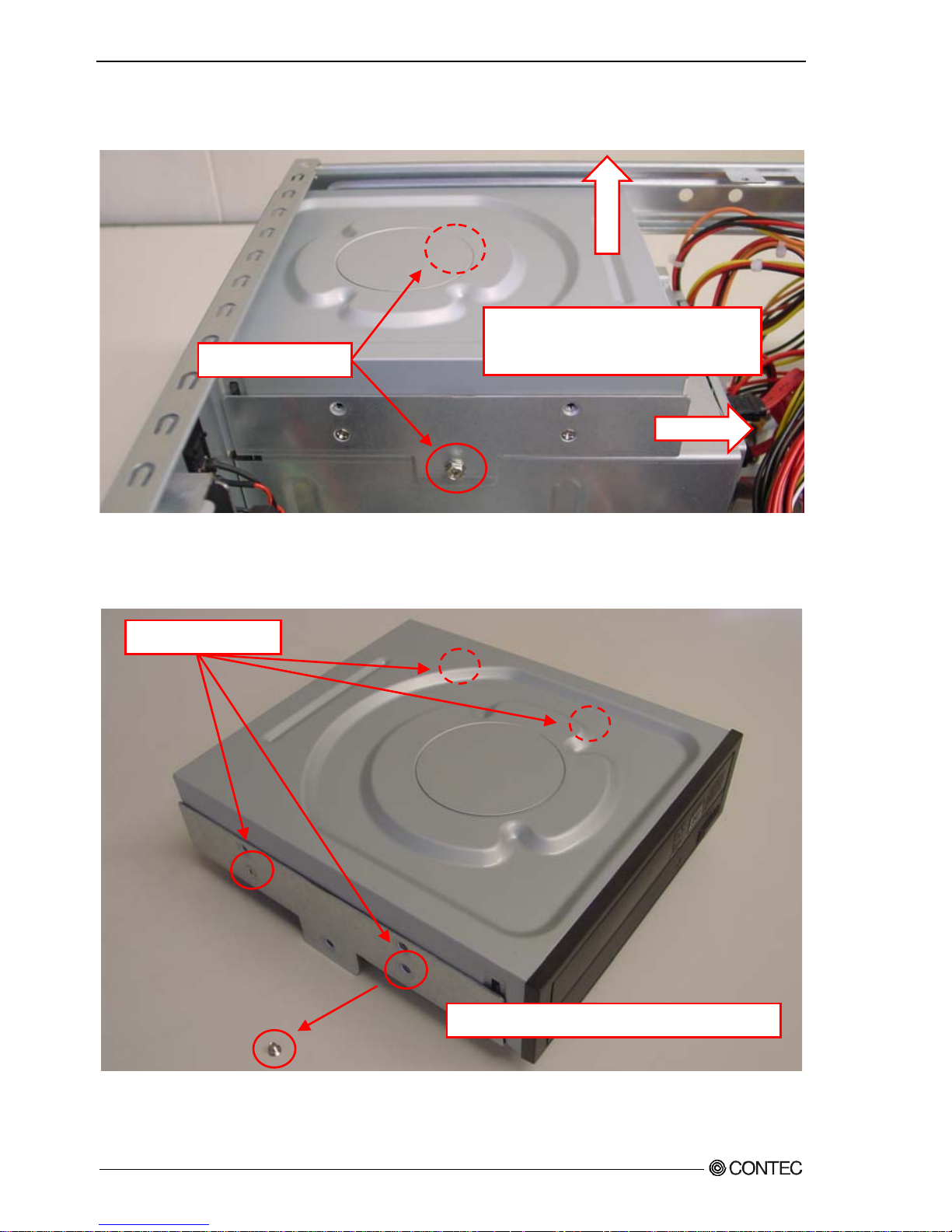
Chapter3 Hardware setup
(2) Remove two screws from the bracket of the optical drive. It moves to horizontal
direction, and it detaches it to the vertical direction.
It moves to horizontal directi on,
and it detaches it to the vertical
direction.
Figure 3.15 Removing the bracket for the optical drive
(3) Remove four screws and remove the optical drive.
Figure 3.16 Removing the optical drive
(4) Reverse the removal procedure and re-insert it.
Remove four screws of the brac ket side.
The two screws
The four screws
34
User’s Manual
Page 41

Chapter3 Hardware setup
◆Attaching the expansion memory
(1) Insert expansion memory into the memory slot.
For DIMM A and DIMM B, use memory compliant with the specification.
DIMM B1
DIMM B2
DIMM A1
DIMM A2
Figure 3.17 Attaching the expansion memory
(2) Lock the memory into the slot.
Figure 3.18 Lock the expansion memory
User’s Manual
35
Page 42

Chapter3 Hardware setup
◆Attaching the extension board
(1) After unscrew the screw, remove the slot cover in the back of the chassis.
Screws
Figure 3.19 Removing the slot cover
(2) The extension board is installed, and it fixes with the screw.
Push in the extension b oard
securely as far as it wi ll go.
Figure 3.20 Attaching the expansion board
Please install it very carefully might interface with the bend of various cables in
the case when you install it according to the size of the extension board that installs
it.
■Maximum dimensions of boards that can be installed:
176mm(L)×110mm(H) (All PCI Express x16,PCI Express x1,PCI bus)
(3) Reverse the attachment procedure and remove it.
36
User’s Manual
Page 43

Chapter3 Hardware setup
◆Replacing the front fan unit
(1) Unscrew and remove the front fan unit.
Figure 3.21 Removing the front fan
The two screws
User’s Manual
37
Page 44

Chapter3 Hardware setup
◆Replacing the dustproof filter
(1) After push the fan braket hole, remove the dustproof filter.
Push
Figure 3.22 Replacing the dustproof filter
(2) Reverse the removal procedure and re-insert it.
※
During attaching the dustproof filter, ensure that the upper and lower it.
38
User’s Manual
Page 45

Chapter3 Hardware setup
◆Replacing the CMOS battery
(1) After remove the front bezel, Remove the CMOS battery.
Figure 3.23 Removing the CMOS battery
(2) The exchanged CMOS battery is prepared and attached.
Confirm the positive and negative
poler, and insert the battery.
-
+
Figure 3.24 Replacing the CMOS battery
■CMOS Battery Specification
Type:CR2/3A
Voltage:3V
Capacity:
1350 mAh
User’s Manual
39
Page 46

Chapter3 Hardware setup
◆Option: Attaching the horizontal installation bracket
(1) Secure horizontal installation brackets with the four supplied screws.
【Vertical installation】 【horizontal installation】
Figure 3.25 Removing the horizontal installation bracket
After attaching the stand, horizontal installation brackets are secured to the
chassis.
During attaching horizontal installation brackets, ensure that the upper and lower
it.
◆Option: Removing the horizontal installation bracket
(1) Remove the four screws anchoring the horizontal installation brackets.
(2) Remove the horizontal installation brackets from the chassis.
40
User’s Manual
Page 47

Chapter3 Hardware setup
◆FG connection
(1) Remove the screw.
(2) Connect the FG cable with the removed screw.
The screw
User’s Manual
41
Page 48

Chapter3 Hardware setup
◆Installation requirements
In order to enjoy reliable use of the VPC-2000 series, maintain the following conditions.
■Installable directions
Please do not use by the following installations, and do not set it up in other directions.
【
V
ertical installation
】
Figure 3.26 Installable direction
【Horizonal installation】
42
User’s Manual
Page 49

Chapter3 Hardware setup
■Space between the main unit and its surroundings
The main unit of the VPC-2000 series is equipped with air vents and fans for regulating
temperature. In order to ensure space for air vents and cables, keep distance described
in the following between the front/rear and surrounding equipment, walls, etc.
Note that in the installation location, air must be able to circulate. Please adjust
the flow of air so as not to exceed the specification temperature of the product.
Moreover, the unit cannot be used in an enclosed space.
※The arrow is a flow of air.
【
V
ertical installation
】
【Horizonal installation】
Figure 3.27 Installation condition
User’s Manual
43
Page 50

Chapter3 Hardware setup
◆Removing the DIO pins
This cover is used for protecting the DIO pins.
(1) Removing the DIO cover screws
Remove the two screws anchoring the chassis to the DIO cover and remove the DIO cover.
Figure 3.28 Removing the DIO cover
(2) Attaching the DIO pin cover
Reverse the procedure of removing the DIO pin cover and attach it.
The two screws
44
User’s Manual
Page 51

Chapter3 Hardware setup
◆Option: Attaching and removing the mirror card
(1) Remove all cables and such connected to the mirror card.
Figure 3.29 Removing all cables
※Starting from the left, the Serial-ATA cables from the upper HDD, lower HDD,
motherboard, and power supply.
※During connection, ensure that the Serial-ATA cables of the upper and lower HDDs are
not reversed.
User’s Manual
45
Page 52

Chapter3 Hardware setup
(2) After remove the front fan, remove four screws anchoring the mirror card.
The four screws
Figure 3.30 Removing four screws anchoring the mirror card
(3) Remove the mirror card.
Figure 3.31 Removing the mirror card
(4) Assembly is the reverse of removal.
※During attaching, ensure that the direction and the upper and lower the mirror card.
46
User’s Manual
Page 53

Chapter4 BIOS setup
Chapter4 BIOS setup
BIOS setup sets various setting during startup. When using the system for the first
time, besure to run BIOS setup. Once set up, the specified details will be backed up.
Do not change items not described in this document.
The system may become unstable and may not start up.
Starting the setup screen
When you turn on the power to the system, if the system is functioning normally, the
“Press DEL to enter SETUP” screen appears. Then press the <DEL> key. After a few seconds,
a setup utility can be started.
AMI BIOS (C) 2006 American Megatrends, Inc.
SMB-MQ570-LLVA BIOS Ver. 1.00
CPU : Intel(R) Core(TM) i5 CPU 660 @ 3.33GHz
Speed : 3.33 GHz
Entering SETUP...
Press F11 for BBS POPUP
The IMC is operating with DDR3 1333MHz, 9 CAS Latency
DRAM Timings: Tras:24/Trp:9/Twr:10/Trfc:74/Twtr:5/Trrd:4/Trtp:5/Tfaw:20
Initializing USB Controllers .. Done.
1912MB OK
USB Device(s) : 2 Hubs
Auto-Detecting Pri Master..IDE Hard Disk
Auto-Detecting Pri Slave...
Figure 4.1 Initial screen
User’s Manual
47
Page 54

Chapter4 BIOS setup
Key operation
This section provides a list of major key-bound functions during setup.
Table 4.1 Key operation list
Key Function
Up Arrow Move to the previous item
Down Arrow Move to the next item
Left Arrow Move to the item on the left (menu bar)
Right Arrow Move to the item on the right (menu bar)
ESC
Main Menu:Quit without saving changes
Submenus:Exit Current page to the next higher
level menu
Move Enter Move to the item you desired
PgUp key Increase the numeric value or make changes
PgDn key Decrease the numeric value or make changes
+ key Increase the numeric value or make changes
- key Decrease the numeric value or make changes
ESC key
Main Menu:Quit and not save changes into CMOS
Status Page Setup Menu and Option Page Setup Menu:
Exit current page and return to Main Menu
F1 key General help on Setup navigation keys
F5 key Load previous values from CMOS
F6 key Load the fail-safe defaults from BIOS default table
F7 key Load the optimized defaults
F10 key Save all the CMOS changes and exit
48
User’s Manual
Page 55

Chapter4 BIOS setup
Main window
When you start the setup utility, the main window appears.
Main Advanced PCIPnP Boot Security Chipset Exit
System Overview
AMI BIOS
Version :**.**.**
Build Data :**/**/**
ID :********
Processor
Intel(R) Core(TM) i7 CPU 860 @
2.80GHz
Speed :2800MHz
Count :1
System Memory
Size :2008MB
System Time
[**:**:**]
System Date
[*** **/**/****]
Figure 4.2 Example of main window screen
1. The cursor keys <↑>, <↓>, <→>, <←> allow you to navigate through menu items and
the <Enter> key allows you to choose among them.
2. After pressing the <F10> key, you can save the current settings by pressing the
<Enter> key or the <Y> key.
◆Setting of the date and time
In order to set the date and time of the calendar clock on the VPC-2000 series, follow
the following steps.
1. Select “System Time” or “System Date” item from “Main” tab.
2. Select time (Time:) or date (Date:) items by pressing the <Page Up> and <Page Down>
keys. You can navigate through items by pressing the cursor keys <←>, <→>.
3. Save setup changes with “Save Changes and Exit” (pressing the <F10> key) and exit.
User’s Manual
49
Page 56

Chapter4 BIOS setup
Setting of the start password
After setting a startup password, you must enter the password when you run the setup
utility and boot the system.
The password can protect system information and files, limiting their use by other users.
Once you register a password, you will not able to clear password features without
the password. Pay careful enough attention in handling your password.
Supervisor Password
Not Installed
User Password
Not Installed
Change Supervisor Password
※1
User Access Level
[Full Access]
Change User Password
※1
Clear User Password
※1
[Setup]
Password Check
Boot Sector Virus Protection [Disabled]
※
1 It is not displayed that Supervisor Password is not set.
Password setting The operation of the setup utility
Supervisor You can change all settings.
User You can refer all setting, but you can not change setting
ofitems.
※Usage restrictions can be decided by setting Supervisor
Password.
1. Select “Change Supervisor Password” from “Security” tab.
2. After it is displayed as “ENTER PASSWORD:”, the password up to six character length
is input and press <Enter> key.
3. Usage restrictions when it access the setup utility by User Password in “User Access
Level” are set.
Options are “No Access”, “View Only” “Limited”, and “Full Access” and select
them arbitrarity.
4. Select “Change User Password”.
5. After it is displayed as “ENTER PASSWORD:”, the password up to six character length
is input and press <Enter> key.
50
User’s Manual
Page 57

Chapter4 BIOS setup
6. Set timing that password is demanded by “Password Check”
Options are “Setup” and “Always” and select them arbitrarity.
Password Check setting Operation
Setup When setup utility starts
Always When setup utility starts and system boot
7. After setting the desired order, press the <Esc> key and return to the Main window.
8. Save setup changes with “Save Changes and Exit” and exit.
Release of setted the password
Although the method for doing this is the same as setting a password, when you enter
the password, press the <Enter> key without entering anything, and the password will
be removed. Removing the Administrator Password works the same way.
Before changing settings in the CMOS Setup, always remove the User Password.
User’s Manual
51
Page 58

Chapter4 BIOS setup
Changing to the device boot order
It is possible to change device boot order.
1st Boot Device [CD/DVD:P0-Optiarc]
2nd Boot Device [SATA:PM-Hitachi HD]
1. Select “Boot Device Priority” menu from “Boot” tab.
2. Change the settings for “1st Boot Device”, “2nd Boot Device”, and etc… .
3. In order to assign top priority to booting from the CD-ROM, move the cursor to the
“1st Boot Device” item and change the setting to “CD/DVD:…”. (Confirm your
choice and setting by pressing the <Enter> key.)
4. After setting the desired order, press the <Esc> key and return to the Main window.
5. Save setup changes with “Save Changes and Exit” and exit.
Selecting to the IDE device
Main Advanced PCIPnP Boot Security Chipset Exit
IDE Configuration
Configure SATA as
[IDE]
¾
SATA 1
[Not Detection]
¾
SATA 2
[Not Detection]
¾
SATA 3
[Not Detection]
¾
SATA 4
[Not Detection]
¾
SATA 5
[Not Detection]
¾
SATA 6
[Not Detection]
Hard Disk Write Protect
[Disabled]
IDE Detect Time Out (Sec)
[35]
ATA(PI) 80Pin Cable Detection
[Host & Device]
1. Select “IDE Configuration” menu from “Advanced” tab.
2. Select “Configuration SATA as” item from “IDE Configuration” windows.
3. Change the settings for “Configuration SATA as”.
(Options are “IDE”, “RAID”, and “AHCI”, but AHCI mode is not supported.)
4. After setting the desired order, press the <Esc> key and return to “Exit” tab.
5. Save setup changes with “Save Changes and Exit” and exit.
52
User’s Manual
Page 59

Chapter4 BIOS setup
Setting for the power on (AT power operation)
by the AC power-supply turning on
Lan1 Controller [Enabled]
LAN1 Option-ROM [Disabled]
Resume On LAN1 [Disasbled]
LAN2 Controller [Enabled]
LAN2 Option-ROM [Disabled]
HAD Controller [Enabled]
SLP_A4# Min. Assertion Width [4 to 5 seconds]
Restore on AC Power Loss [Power On]
Resume On Ring [Disabled]
Resume On PCI Express/LAN2 [Disabled]
Resume On PCI Device [Disabled]
1. Select “South Bridge Chipset Configuration” menu from “Chipset” tab.
2. Select “Restore on AC Power Loss” menu from “South Bridge Chipset Configuration”
windows.
3. Change “On” the settings for “Restore on AC Power Loss”.
4. After setting the above-mentioned 3, press the <Esc> key and return to “Exit”.
5. Save setup changes with “Save Changes and Exit” and exit.
User’s Manual
53
Page 60

Chapter4 BIOS setup
Factory default setting
This section describes the CMOS Setup Utility’s factory default settings.
By selecting “Load Optimal Defaults” in the Exit tab of the CMOS Setup Utility, you
can restore our factory settings. For operational instructions, follow the following
steps.
1. Select “Load Optimal Defaults” menu from Exit tab of the setup screen.
2. You are prompted to confirm that you are restoring to initial conditions. Press the
<Y> and <Enter> keys.
3. Save setup changes with “Save Changes and Exit” and exit.
The following section describes parameters for the factory default settings of each
setting in the CMOS Setup Utility.
Do not change settings other than the CMOS Setup Utility settings specifically
described in this document. The OS may not function normally otherwise.
We assume no responsibility for trouble caused by changing settings other than the
CMOS Setup Utility settings specified.
54
User’s Manual
Page 61

Chapter4 BIOS setup
◆MAIN
AMI BIOS
Version :**.**.**
Build Data :**/**/**
ID :********
Processor
Intel(R) Core(TM) i7 CPU 860 @ 2.80GHz
Speed :2800MHz
Count :1
System Memory
Size :2008MB
System Time [**:**:**]
System Data [*** **/**/****]
※ As the Main tab differ according to date and PC configuration, the above figure is
a sample.
◆Advanced
¾
CPU Configuratio n
¾
IDE Configuration
¾
SuperIO Configuration
¾
Hardware Health Configuration
¾
ACPI Configuration
¾
AHCI Configuration
¾
ASF Configuration
¾
Remote Access Configuration
¾
USB Configuration
¾
Trusted Comput ing
User’s Manual
55
Page 62

Chapter4 BIOS setup
■CPU Configuration
Manufacturer :Intel
Intel(R) Core(TM) i7 CPU 860 @ 2.80GHz
Frequency :2.80GHz
BCLK Speed :133MHz
Cache L1 :256 KB
Cache L2 :1024 KB
Chace L3 :8192 KB
Ratio Status :Unlocked (Min:09,Max:21)
Ratio Actual Value :21
Ratio CMOS Setting
[21]
Hardware Prefetcher
[Enabled]
Adjacent Cache Line Prefetch
[Enabled]
MPS and ACPI MADT ordering
[Modern ordering]
Max CPUID Value Limit
[Disabled]
Intel(R) Virtualization Tech
[Enabled]
Execute-Disable Bit Capability
[Enabled]
Intel(R) HT Technology
[Enabled]
Active Processor Cores
[All]
A20M
[Disabled]
Intel(R) SpeedSte(tm) tech
[Enabled]
Intel(R) TurboMode tech
[Enabled]
Intel(R) C-STATE tech
[Disabled]
■IDE Configuration
Configure SATA as
[IDE]
¾
SATA 1
[Not Detection]
¾
SATA 2
[Not Detection]
¾
SATA 3
[Not Detection]
¾
SATA 4
[Not Detection]
¾
SATA 5
[Not Detection]
[Not Detection]
¾
SATA 6
Hard Disk Write Protect
Hard Disk Write Protect
IDE Detect Time Out (Sec)
IDE Detect Time Out (Sec)
ATA(PI) 80Pin Cable Detection
ATA(PI) 80Pin Cable Detection
56
User’s Manual
Page 63

Chapter4 BIOS setup
■SuperIO Configuration
WatchDog Function [Disabled]
OnBoard Floppy Controller [Enabled]
Serial Port1 Address [3F8/IRQ4]
Serial Port2 Address [2F8/IRQ3]
Parallel Port Address [378]
Parallel Port Mode [ECP & EPP]
EPP Version [1.9]
ECP Mode DMA Channel [DMA3]
Parallel Port IRQ [IRQ7]
Serial Port3 Adress [CA0]
Serial Port3 IRQ [11]
Serial Port3 Mode [Normal]
Serial Port4 Addrerss [CA8]
Serial Port4 IRQ [10]
■Hardware Health Configuration
Chassis Intrusion [Disabled]
CPU Warning Temperature [Disabled]
ACPI Shutdown Temperature [Disabled]
System Temperature 26℃/78℉
CPU Temperture 39℃/102℉
CPUFAN Speed 2008 RPM
SYSFAN1 Speed 2250 RPM
SYSFAN2 Speed 0 RPM
Vcore 1.160 V
+3.3V 3.312 V
+5V 5.056 V
+12V 11.904 V
3VSB 3.456 V
5VSB 5.088 V
VBAT 3.007 V
CPUFAN0 Mode Setting [Disabled]
※Because the numerical value is different according to the PC environment used, the
above-mentioned reaches the reference value.
User’s Manual
57
Page 64

Chapter4 BIOS setup
■ACPI Configuration
¾
General ACPI Configuration
¾
Chipset ACPI Configuration
●General ACPI Configuration
Syspend mode [Auto]
Repost Video on S3 Resume [No]
●Chipset ACPI Configuration
APIC ACPI SCI IRQ [Disabled]
High Performance Event Timer [Disabled]
■AHCI Configuration
AHCI BIOS S u ppo r t
[Enabled]
¾
AHCI Port1 [Not Detected]
¾
AHCI Port2 [Not Detected]
¾
AHCI Port3 [Not Detected]
¾
AHCI Port4 [Not Detected]
¾
AHCI Port5 [Not Detected]
¾
AHCI Port6 [Not Detected]
■ASF Configuration
ASF Support [Enabled]
■Remote Access Configuration
Remote Access [Disabled]
58
User’s Manual
Page 65

Chapter4 BIOS setup
■USB Configuration
Module Version – 2.24.5-13.4
USB Devices Enabled :
2 Hubs, 1 Drive
Legacy USB Support [Enabled]
USB 2.0 Controller Mode [HiSpeed]
Legacy USB1.1 HC Support [Enabled]
¾
USB Mass Storage Device Configuration
■Trunsted Configuration
TCG/TPM SUPPORT [No]
■PCIPnP
Clear NVRAM [No]
◆Boot
¾
Boot Setting Configuration
¾
Boot Device Priority
¾
Hard Disk Drives
■Boot Setting Configuration
Quick Boot [Enabled]
Quiet Boot [Disabled]
AddOn ROM Display Mode [Force BIOS]
Bootup Num-Lock [On]
PS/2 Mouse Support [Auto]
Wait For ‘F1’ IF Error [Enabled]
Hit ‘DEL’ Message Display [Enabled]
Interrupt 19 Capture [Disabled]
User’s Manual
59
Page 66

Chapter4 BIOS setup
■Boot Device Priority
1st Boot Device [CD/DVD:P0-Optiarc]
◆Security
Supervisor Password Not Installed
User Password Not Installed
Change Supervisor Password
Change User Password
Boot Sector Virus Protection [Disabled]
◆Chipset
¾
North Bridge Configuration
¾
South Bridge Configuration
¾
Intel AMT Configuration
¾
Intel VT-d Configuration
¾
ME Subsystem Configuration
¾
VE Subsystem Configuration
60
User’s Manual
Page 67

Chapter4 BIOS setup
■North Configuration
IMC Type : *Field Family IMC
Memory Remap Feature [Enabled]
Fast MRC [Disabled]
PCI MMIO Allocation : 4GB To 3072MB
DRAM FreQuency [Auto]
Configure DRAM Timing by SPD [Auto]
Memory Hole [Disabled]
DRAM Margin Ranks [Disabled]
Initiate Graphic Adapter [PCIE/PCI]
IGD GTT Graphic smemory size [No VT mode. 2MB]
NB PCIE Configuration
PEG Force GEN1 [Disabled]
■Souoth Configuration
LAN1 Controller [Enabled]
LAN1 Option-ROM [Disabled]
Resume On LAN1 [Disabled]
LAN2 Controller [Enabled]
LAN2 Option-ROM [Disabled]
HDA Controller [Enabled]
SLP_A4# Min. Assertion Width [4 to 5 seconds]
Restore on AC Power Loss [Power On]
Resume On Ring [Disabled]
Resume On PCI Express/LAN2 [Disabled]
Resume On PCI Device [Disabled]
User’s Manual
61
Page 68

Chapter4 BIOS setup
■Intel AMT Configuration
Intel AMT Support [Enabled]
Force IDER [Disabled]
Force SOL [Disabled]
Unconfigure AMT/ME [Disabled]
Activate Remote Assistance [Disabled]
MEB# Ctrl+P Delay (Seconds) [ 0]
■Intel VT-d Configuration
Intel VT-d [Disabled]
■ME Subsystem Configuration
Boot Block HECI Message [Disabled]
HECI Message [Enabled]
End Of Post S5 HECI Message [Enabled]
ME HECI Configuration
ME-HECI [Enabled]
ME-IDER [Enabled]
ME-KT [Enabled]
Management Engine Version : 6.0.0.1104
■VE Subsystem Configuration
VECI Message [Disabled]
◆Exit
Save Changes and Exit
Discard Changes and Exit
Discard Changes
Load Optimal Defaults
Load Faisafe Defaults
62
User’s Manual
Page 69

Chapter5 Each component function
Chapter5 Each component function
Component name
◆VPC-2000 front view
Optical drive unit cover
Power seitch
Reset switch
HDD LED
User LED1
User LED2
Hardware mirroring LED
USB 2.0
Optical drive unit
Cooler fan (suction)
※After removing the front face
POWER LED
※Please refer to Chapter 8 for details.
CMOS battery
Hard disk drive
User’s Manual
63
Page 70

Chapter5 Each component function
◆VPC-2000 rear view
Mouse connector
Keyboard connector
COM2
DVI
Ethernet connector
USB connector
COM3
COM4
USB connector
Digital I/O connector
Printer port connector
FG terminal
Motherboard interface
COM1
CRT
LINE IN
LINE OUT
MIC IN
64
User’s Manual
Page 71

Chapter5 Each component function
Component Function
◆Keyboard interface
A connector for connecting a keyboard is provided. Connector name is KB(6Pin mini-DIN).
Table 5.1 Keyboard connector
ピン番号
1
2
3
4
5
6
機能
K.B DATA
N.C.
GND
+5V
K.B CLOCK
N.C.
Pin No. Function
3
6
4
2
1
5
◆Mouse interface
A connector for connecting a mouse is provided. Connector name is MOUSE(6Pin mini-DIN).
Table 5.2 Mouse connector
ピン番号
1
2
3
4
5
6
機能
MOUSE DATA
N.C.
GND
+5V
MOUSE CLOCK
N.C.
3
6
4
2
1
5
Fun ionct
.Pin No
User’s Manual
65
Page 72

Chapter5 Each component function
◆Serial port interface
< RS-232C port (COM1,COM2,COM3,COM4)>
Three RS-232C-compliant serial port connectors are provided. Resources can be either
assigned or reserved for each port independently through BIOS setup (see Chapter 4).
Table 5.3 SERIAL1, 2 I/O address、interrupt
COM I/O Address Interrupt
3F8h
IRQ4
COM1
IRQ4
3E8h
IRQ3
2E8h
2F8h
IRQ3
COM2
IRQ4
3E8h
IRQ3
2E8h
CA0h
IRQ11
CA8h
COM3
IRQ10
CB0h
CB8h
CA0h
IRQ10
CA8h
COM4
IRQ11
CB0h
CB8h
The factory default settings of the BIOS are as follows.
COM1:3F8h,IRQ4
COM2:2F8h,IRQ3
COM3:CA0h,IRQ11
COM4:CA0h,IRQ10
Table 5.4 Serial port connector
Connector D-SUB 9 Pin (MALE)
1 5
9
6
No.4-40UNC
インチネジ
Inch screw
Pin No. Signal Direction
1 DCD Input
2 SIN Input
3 SOUT Output
4 DTR Output
5 GND -
6 DSR Input
7 RTS Output
8 CTS Input
9 RI Input
66
User’s Manual
Page 73

Chapter5 Each component function
◆CRT interface
A connector for connecting a CRT is provided. Connector name is VGA(15PinD-SUB).
Table 5.5 CRT connector
Connector D-SUB 15 Pin (FEMALE)
15
1115
10 6
Pin No. Function Pin No. Function
1 RED 9 VCC_TMDS
2 GREEN 10 GND
3 BLUE 11 NC
4 NC 12 DDC_DAT
5 GND 13 HSYNC
6 GND 14 VSYNC
7 GND 15 DDC_CLK
8 GND
User’s Manual
67
Page 74

Chapter5 Each component function
◆DVI interface
A connector for connecting a DVI is provided. Connector name is DVI(29Pin DVI-I).
Table 5.6 DVI connector
Connector DVI-I 29 Pin (FEMALE)
Pin No. Function Pin No. Function Pin No . Function
1 TMDS 2- 11 TMDS 1/3 Shield 21 TMDS 5+
2 TMDS 2+ 12 TMDS 3- 22 TMDSCLK Sheild
3 TMDS 2/4 Shield 13 TMDS 3+ 23 TMDSCLK+
4 TMDS 4- 14 +5V 24 TMDSCLK5 TMDS 4+ 15 GND C1 RED
6 DDC_CLK 16 HOTPLUG_DETECT C2 GREEN
7 DDC_DATA 17 TMDS 0- C3 BLUE
8 VSNC 18 TMDS 0+ C4 HSYNC
9 TMDS 1- 19 TMDS 0/5 Shield C5 AGND
10 TMDS 1+ 20 TMDS 5- C6 AGND
68
User’s Manual
Page 75

Chapter5 Each component function
◆Printer port interface
One printer port interface is provided. Resources can be either assigned or reserved
through BIOS setup (see Chapter 4).
Table 5.7 Printer port and I/O address
LPT I/O Address Interrupt DMA
DMA 0
378
278
3BC
IRQ 5
IRQ 7
1
DMA 1
DMA 3
The factory default settings of the BIOS are as follows.
Mode:[ECP & EPP]、Base I/O address:[378]、Interrupt:[IRQ 7]、
EPP version:[1.9]、DMA Channel:[DMA3]
I/O address [3BC] can be selected only in Modes [Bi-Directional]. DMA Channel is
used only in Mode [ECP].
Table 5.8 Printer port connector
Connector D-SUB 25 pin (FEMALE)
13
1
1425
Pin No. Signal Direction Pin No. Signal Direction
1 STB Output 14 AFD Output
2 D0 Output 15 ERR Input
3 D1 Output 16 INIT Output
4 D2 Output 17 SLIN Output
5 D3 Output 18 GND -
6 D4 Output 19 GND -
7 D5 Output 20 GND -
8 D6 Output 21 GND -
9 D7 Output 22 GND -
10 -ACK Input 23 GND -
11 BUSY Input 24 GND -
12 PE Input 25 GND -
13 SLCT Input -
Fixed screw : No.4-40UNC inch screw
User’s Manual
69
Page 76

Chapter5 Each component function
◆Reset switch
Push this button when resetting hardware.
◆Power switch
Push this button at power-on. In order to turn off the power forcibly, hold it down for
four seconds or longer.
◆USB port
Six USB interfaces are provided.
Table 5.9 USB connector
ピン番号
A1
A2
A3
A4
信号名
USB0 Vcc
USB0 -Data
USB0 +Data
USB0 GND
ピン番号
B1
B2
B3
B4
信号名
USB1 Vcc
USB1 -Data
USB1 +Data
USB1 GND
B1 B4
A1 A4
Pin No Pin Noncti
nc
Fu onti
. Fu on .
70
User’s Manual
Page 77

Chapter5 Each component function
◆Ethernet
The VPC-2000 is equipped with two channels for Ethernet.
・Network type : 10BASE-T/100BASE-TX/1000BASE-T
・Transmission speed : 10M/100M/1000Mbps
・Max. network path length : 100m/segment
・Controller : Intel 82578 Gigabit Ethernet (LAN1)
Intel 82583V Gigabit Ethernet (LAN2)
* 1000Mbps operation requires a cable of category 5E or greater.
Table 5.10 Ethernet connector
Connector type RJ-45
LINK/ACT 10/100/1000M
8
1
Pin No. Signal name Function
1 TD+ Transmission data(+)
2 TD- Transmission data(-)
3 RD+ Receive data(+)
4 GND Ground
5 GND Ground
6 RD- Receive data(-)
7 GND Ground
8 GND Ground
LEDs for display of network statuses
LINK/ACT LED :(Yellow) Lighting at the normal connection.
(Yellow) Blinking at the data transmission and
receive.
10/100/1000M LED :Turning off at the 10M operation.
(Orange) Lighting at the 100M operation.
(Green) Lighting at the 1000M operation.
User’s Manual
71
Page 78

Chapter5 Each component function
◆Digital I/O interface
This interface controls digital I/O with two rows of six pins (JDIO1, JDIO2).
Among the eight DIO pins, two output pins (02, 03) are used for the user LED on the front.
The digital I/O interface is internally insulated.
Table 5.11 Digital I/O Connector
1
6 7
JDIO1
JDIO2
JDIO1 JDIO2
Pin No. Signal Pin No. Signal
1 I0 7 O0
2 I1 8 O1
3 I2 9 O2 (Connected prohibition)
4 I3 10 O3 (Connected prohibition)
5 PWRON 11 COMPO
6 RST 12 COMPI
1)I0~I3 (JDIO1 Pin No. 1~4)
Input signal : You can input Input0, Input1, Input2, and Input3.
2)O0~O3 (JDIO2 Pin No. 7~10)
Output signal : You can output Onput0, Onput1, Onput2, and Onput3.
※You can not use Output2,3 because they are used for the user LED on the front.
3)PWRON,RST (JDIO1 Pin No.5,6)
Short-circuiting PWRON and GND or RST and GND triggers the same operation as pushing
the Power button or Reset button on the front.
※However, the power-supply from the outside is necessary.
4)COMPO,COMPI (JDIO2 Pin No.11,12)
These are used for the power-supply from the outside.
COMPO is GND and COMPI is VCC.
72
User’s Manual
Page 79

Chapter5 Each component function
Internal equivalent circuit chart of the remote power and the remote reset
VPC-2000 internal
VPC-2000 external
Example of custom er constr uction circuit
External I/O connection VPC-2000 internal equivalent circuit diagram
VPC-2000 external
VPC-2000 internal
Example of custom er constr uction circuit
User’s Manual
73
Page 80

Chapter5 Each component function
◆Audio interface
The Audio interface. is provided.
Table 5.12 Audio connector
Bule
Green
Pink
Pin No. Signal name
Blue Line-In
Green Line-Out
Pink Mic-In
74
User’s Manual
Page 81
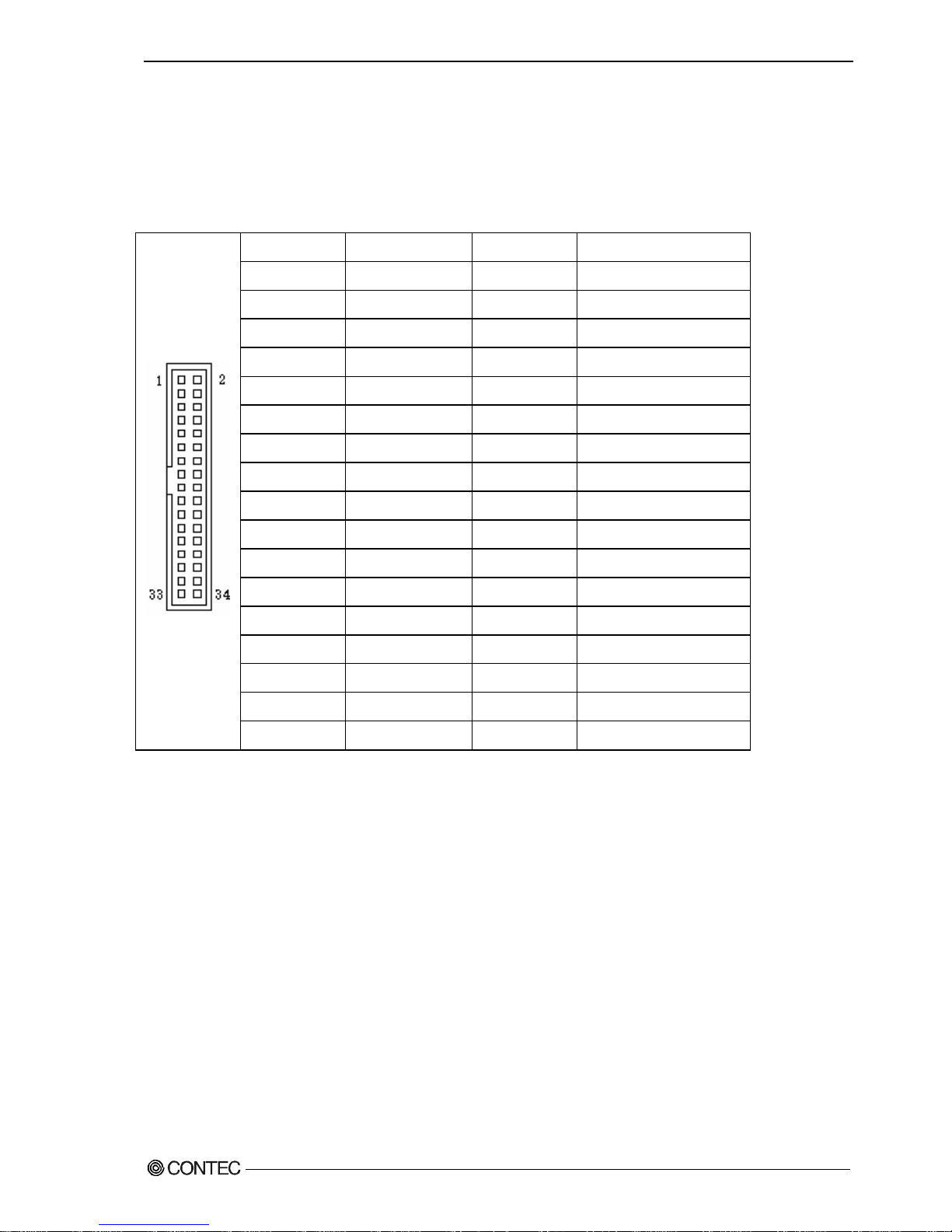
Chapter5 Each component function
◆Floppy disk interface
The floppy disk interface is provided.
Table 5.13 Floppy disk connector
Pin No. Signal name Pin No. Signal name
1 GND 2 RWC
3 GND 4 NC
5 Key (No Pin) 6 NC
7 GND 8 Index-
9 GND 10 MOTA-
11 GND 12 NC
13 GND 14 DSA-
15 GND 16 NC
17 GND 18 FDIR-
19 GND 20 STEP-
21 GND 22 WDATA-
23 GND 24 WGATE-
25 GND 26 Track 0-
27 GND 28 Write Protect-
29 GND 30 Read Data-
31 GND 32 Head Select-
33 GND 34 Diskette Change-
User’s Manual
75
Page 82

Chapter5 Each component function
◆Serial ATA interface
Six serial ATA port interfaces are provided.
Table 5.14 Serial ATA connector
Pin No. Signal name
1 GND
2 TX+
3 TX-
4 GND
5 RX-
6 RX+
7 GND
76
User’s Manual
Page 83

Chapter6 Software utirity
Chapter6 Software utirity
This chapter describes the driver DVD included with the VPC-2000 series. This driver
DVD includes drivers and software necessary for the VPC-2000 series.
This driver DVD does not provide Autorun functionality. Install drivers and software
manually through Windows Explorer after inserting this driver DVD into the CD/DVD-ROM
drive.
The contents of the driver DVD are subject to change without prior notice.
Pre-installed models are not accompanied by a driver DVD. A driver DVD is included with
models that come without an OS.
Driver DVD
The directory structure of the driver DVD is shown below.
In the recovery media, the following directory doesn't exist.
Please download each driver and utility from our homepage for the pre-install model.
OEM
├─Documents
├─Drivers ← Pre-installed models have these installed in the OS.
│ ├─Audio
│ ├─Chipset
│ ├─Lan
│ ├─Raid
│ ├─Tpm
│ └─Vga
├─IO-Lib(NT) ← P re-installed models haven’t these installed in the OS.
├─TinyRAS ← P re-installed models haven’t these installed in the OS.
└─HWRAID ← Pre-installed models haven’t these installed in the OS.
・Documents :A copy of this information is stored here.
・Drivers :Versions of the installation files for the chipset, graphics,
LAN, audio, and security chip drivers are included separately
for Windows XP and Windows 7.
・IO-Lib(NT) :Install file of general purpose I/O driver is stored here.
・TinyRAS :Install file of RAS tool is stored here.
・HWRAID :Install file of hardware raid tool tool is stored here.
User’s Manual
77
Page 84

Chapter6 Software utirity
Various drivers
Install chipset, graphics, LAN, audio, and security chip drivers in the “Drivers”
folder. Since the driver to install depends on which OS is used, install the drivers
appropriate for your OS.
IO-Lib(NT)
The general purpose I/O driver can be installed using the “LZF826IO_312R.EXE” in the
“IO-Lib(NT)” folder. Set it up according to the following procedure.
1. Extracting the file
Specify the destination for extracted files in the following screen and select “OK”.
2.File Directory
In the destination folder for the extracted files, files will be created using the
following directory structure.
Specification folder
├─APIPAC
├─INF
└─Readme
3.Install file
Execute setup.exe in the subfolder “\APIPAC\Runtime\IOLIB\Disk1” within the
specified folder.
78
User’s Manual
Page 85

Chapter6 Software utirity
4.Language select
Select a language and click “Next”.
5.Setup
Click “Next”.
User’s Manual
79
Page 86

Chapter6 Software utirity
6.Choose destination location
Specify a destination folder for installation and click “Next”.
7.Program folder
After specifying the program folder, click “Next”.
80
User’s Manual
Page 87

Chapter6 Software utirity
8.Completion
Click “Finish”. After clicking “Finish”, restart the PC.
Install of IO-Lib(NT) has been completed.
User’s Manual
81
Page 88

Chapter6 Software utirity
Set it up according to the following procedure after IO-Lib installed.
9.Starting the IO-Lib(NT)
Selects “Start menu” – “All Programs” – “CONTEC API-PAC(W32)” –
“IO-LIB(W32)” – “IO-LIB Configuration” to start IO-Lib Configuration.
10.IO-Lib(W95/NT) Configuration
Click “OK”.
82
User’s Manual
Page 89

Chapter6 Software utirity
11.Set registration
Click “OK”.
12.Completion
Click “OK”. After clicking “OK”, restart the PC.
Setup of IO-Lib(NT) has been completed.
User’s Manual
83
Page 90

Chapter6 Software utirity
RAS tool
The RAS tool can be installed using the “TinySetup.msi” in the “TinyRAS” folder.
Set it up according to the following procedure.
1.Setup
Click “Next”.
2. Select installation folder
Select the installation destination and one of the RAS user options. Click “Next”.
84
User’s Manual
Page 91

Chapter6 Software utirity
3.Confirm installation
Click “Next”.
4.Install
Installation is in progress. Completion takes some time. Wait for a while.
User’s Manual
85
Page 92

Chapter6 Software utirity
5.Completion
Click “Close”. After clicking “Close”, restart the PC.
Install of RAS tool has been completed.
Set it up according to the following procedure after RAS tool installed.
6. Selecting the registry
Selects “Start menu” – “All Programs” – “CONTEC” – “Config” – “VPC-2000”
to execute the registry.
86
User’s Manual
Page 93

Chapter6 Software utirity
7. Registry addition
Click “Next”.
8. Completion
Click “OK”. After clicking “OK”, restart the PC.
Setup of RAS tool has been completed.
User’s Manual
87
Page 94

Chapter6 Software utirity
◆Watch-Dog Timer (WDT) Setting
You can set a watchdog timer by using tRasWdtmr function. Execute this function
periodically and program it so that the watchdog timer will not be reset.
Prototype of function
int tRasWdtmr ( DWORD second )
Argument Reset time (in seconds) of the watchdog timer can be set.
Input range is 0~255.
When 0 is specified, the watchdog timer is deactivated.
Return
value
Returns 0 when execution of the function succeeds and a value other than
0 when it fails.
Explanation Although the time can be set in seconds by using this function, there is
an error margin of three seconds in the reset time of the watchdog timer.
For example, if the reset time of a watchdog timer is set to 30 seconds
later, you have to reconfigure a watchdog timer within 27 seconds.
When the watchdog timer is reset, data being written to storage is not
guaranteed. As Windows cannot handle shutdowns, if Windows is writing
system data, Windows system files may be corrupted.
Header file TinyRAS.h
Inport library TinyRAS.lib
DLL file TinyRAS.dll
The header file and the library file are stored in the place specified when TinyRas is
installed. (
Initial storage place: c:\ Program Files\CONTEC\TinyRAS\
)
Example programming
#include “TinyRAS.h”
int main ( void ){
tRasWdtmr(10); // The watch-dog timer after ten seconds resets it.
return 0;
}
88
User’s Manual
Page 95

Chapter6 Software utirity
◆Hardware monitor
You can monitor hardware information such as voltage information, temperature
information, and the number of fan revolutions, by using the tRasHwMon function.
Prototype of function
int tRasHwMon ( HMVAL *val );
Argument Specifies the first pointer to the HMVAL structure.
※ The HMVAL structure is defined in the TinyRAS.h file.
Return
value
Returns 0 when execution of the function succeeds and a value other than
0 when it fails.
Header file TinyRAS.h
Inport library TinyRAS.lib
DLL file TinyRAS.dll
The header file and the library file are stored in the place specified when TinyRas is
installed. (
Initial storage place: c:\ Program Files\CONTEC\TinyRAS\
)
・CPU temperature values given by the hardware monitoring function installed in
the VPC-1000 series will vary according to the stepping of the installed CPU.
Since the bundled software corrects the value according to the CPU, there is
no problem. However, if you use the hardware monitoring function through direct
hardware access or the standard Windows API, give consideration to the value
variations for each CPU.
・If a fan is replaced with service parts, fan speed may be different.
User’s Manual
89
Page 96

Chapter6 Software utirity
/*+++++++++++++++++++++++++++++++++++++++++++
Values obtained through the hardware monitoring function
++++++++++++++++++++++++++++++++++++++++++++*/
typedef struct {
DWORD f_cpu; // CPU Fan
DWORD f_sys; // chassis Fan
DWORD f_misc1; // Other Fan1
DWORD f_misc2; // Other Fan2
float t_cpu; // CPU Temperature
float t_sys; // System Temperture
float t_misc; // Other Temperture
float v_cpu; // CPU Core Voltage
float v_mem; // Memory Voltage
float v_vcc3; // VCC 3.3V
float v_vcc5; // VCC 5V
float v_p12v; // +12V
float v_m12v; // -12V
float v_m5v; // -5V
float v_5vsb; // 5V Stanby
float v_3vsb; // 3V Stanby
float v_batt; // Battery
}HMVAL, *pHMVAL;
90
User’s Manual
Page 97

Chapter6 Software utirity
Example programming
#include <stdio.h>
#include <string.h>
#include “TinyRAS.h”
int main ( void ){
HMVAL val;
(void)memset(&val, 0, sizeof(val));
(void)tRasHwMon(&val);
printf("CPUtemperature %.1f℃\n", val.t_cpu) ;
printf("CPUvoltage %.1f[V]\n", val.v_cpu) ;
printf("CPUFan %d[rpm]\n", val.f_cpu) ;
return 0 ;
}
Set the threshold value optionally. (例: Sound an alarm for excessive temperatures,
etc…)
User’s Manual
91
Page 98

Chapter6 Software utirity
◆General purpose input
tRasIoRead functions allow you to get the status of General PurposeI/OPort.
Prototype of function
General Purpose Input BYTE tRasIoRead ( BOOL isRead );
Argument If TRUE is specified, gets the status of the general-purpose input port.
If FALSE is specified, gets the status of the general-purpose output port.
Return
value
Returns byte data from a port specified by an argument.
For the general purpose input(isRead=TRUE)
bit 7 6 5 4 3 2 1 0
Meaning - - - - IO4 IO3 IO2 IO1
汎用出力(isRead=FALSE)の場合
bit 7 6 5 4 3 2 1 0
Meaning - - - - DO4 DO3 DO2 DO1
※ DO3(LED1) and DO4(LED2) are allocated to the two front LEDs.
Header file TinyRAS.h
Inport library TinyRAS.lib
DLL file TinyRAS.dll
The header file and the library file are stored in the place specified when TinyRas is
installed. (
Initial storage place: c:\ Program Files\CONTEC\TinyRAS\
)
Example programming
#include <stdio.h>
#include “TinyRAS.h”
int main ( void ){
BYTE dat=0;
dat = tRasIoRead(TRUE); // Acquiring the state of input port.
printf(“the state of input port %02X\n”, dat);
return 0;
}
92
User’s Manual
Page 99

Chapter6 Software utirity
◆General purpose output
The tRasIoWrite function allows you to control the general-purpose output port.
Prototype of function
General Purpose Output int tRasIoWrite ( BYTE data);
Argument Specifies data output to the general-purpose output port.
Output data corresponds to the following bits.
bit 7 6 5 4 3 2 1 0
Meaning - - - - DO4 DO3 DO2 DO1
※ DO3(LED1) and DO4(LED2) are allocated to the two front LEDs.
Return
value
When succeeding in executing the function, the specified data is returned.
When failing, the error code is returned.
Header file TinyRAS.h
Inport library TinyRAS.lib
DLL file TinyRAS.dll
The header file and the library file are stored in the place specified when TinyRas is
installed. (
Initial storage place: c:\ Program Files\CONTEC\TinyRAS\
)
Example programming
#include “TinyRAS.h”
int main ( void ){
BYTE dat=0;
dat = tRasIoRead(FALSE);
(dat & 0x08) ? dat &= ~0x08 : dat |= 0x08; // LED:ONÆOFF, OFFÆON
(void)tRasIoWrite(dat);
return 0;
}
User’s Manual
93
Page 100

Chapter6 Software utirity
Hardware RAID monitoring tool
This sections describes the utility which monitors the status of HDDs connected to a
mirror card. However, in order to use the utility described in this document, the
following utilities need to have been installed in Windows.
・IO-Lib ← To install this utility, refer to this chapter “Software Utility”.
・TinyRAS ← To install this utility, refer to this chapter “Software Utility”.
The latest version utirity downloads from CONTEC web site.
◆Setup
The hardware raid monitoring tool can be installed using the “hwRaid.msi” in the
“HWRAID” folder. Set it up according to the following procedure.
1.Setup
Click “Next”.
94
User’s Manual
 Loading...