

Page 1

SVR-MMF(FIT)
F&eIT Series
Monitoring & Control Server
User’s Guide
Page 2

Copyright
Copyright 2002 CONTEC Co., LTD. ALL RIGHTS RESERVED
No part of this document may be copied or reproduced in any form
by any means without prior written consent of CONTEC Co., LTD.
CONTEC Co., LTD. makes no commitment to update or keep
current the information contained in this document.
The information in this document is subject to change without
notice.
All relevant issues have been considered in the preparation of this
document. Should you notice an omission or any questionable item
in this document, please feel free to notify
CONTEC Co., LTD.
Regardless of the foregoing statement, CONTEC assumes no
responsibility for any errors that may appear in this document nor
for results obtained by the user as a result of using this product.
Trademarks
All company and product names that are referred to in this manual
are generally trademarks or registered trade.
SVR-MMF(FIT) i
Page 3

Product Configuration
- System unit...1
- Manual...1
- Power connector...1
Unpacking:
This product is specially packed in an anti-static bag to prevent
damage in shipping.
Check the contents to make sure that you have everything listed
above. If you do not have all the items, contact your distributor or
CONTEC group office where you purchased.
Note!
Do not remove the product from its protective packaging until the
computer case is open and ready for installation. Electrical static
can cause damage to electrical components.
SVR-MMF(FIT)ii
Page 4

Table of Contents
Copyright............................................................................i
Trademarks........................................................................i
Product Configuration..................................................... ii
1. Introduction ............................................................. 1
Features ........................................................................1
System Configuration Image.......................................2
Limited One-Year Warranty ........................................4
How to Obtain Service..................................................4
Liability.........................................................................4
Handling Precautions...................................................5
About the Manual.........................................................6
2. Overview.................................................................. 7
Specifications ....................................................................7
System Configuration.......................................................9
Example of System Configuration...............................9
External Dimensions......................................................10
3. Functions of the Various Components ...................... 11
Nomenclature..............................................................11
Keyboard/Mouse Interface.........................................12
Serial Port Interface ...................................................13
CRT Interface..............................................................14
CompactFlash Slot .....................................................14
RUN LED....................................................................15
STATUS LED..............................................................15
CF LED........................................................................15
SHUTDOWN SW........................................................15
USB Port.....................................................................15
Ethernet......................................................................16
POWER .......................................................................17
SVR-MMF(FIT) iii
Page 5

4. Hardware Setup ..................................................... 19
Getting Started...............................................................19
Mounting the Module.....................................................20
Mounting on a DIN Rail .............................................23
Connection Method.........................................................26
Supplying the Power to the Controller Module........26
Installation Conditions...................................................27
5. System Setup ......................................................... 29
Setting Procedure...........................................................29
Verifying the Operation..................................................30
State Check from a Browser......................................30
6. Creation and a Display of a Monitoring Screen ......... 43
Operation Procedure.......................................................43
Basic Operations .............................................................46
Types of Available Components and Their Overview...50
Monitoring-Screen Operation ........................................62
7. Creation and a Display of a Processing Task ............ 65
Operation Procedure.......................................................65
Basic Operations .............................................................72
The Kind and Outline of Parts Which Can Be Used....76
Sample.............................................................................85
8. Troubleshooting ...................................................... 95
9. Appendix................................................................ 97
F&eIT Protocol Specifications........................................97
Basic Specifications....................................................99
Control Information..................................................106
List of F&eIT Series of Products .................................109
SVR-MMF(FIT)iv
Page 6

List of Figures
Figure 2.1. System Configuration Diagram ................................ 9
Figure 2.2. SVR-MMF(FIT) External Dimensions................... 10
Figure 3.1. Nomenclature..........................................................11
Figure 4.1. Mounting on a DIN Rail < 1 / 3 >......................... 23
Figure 4.1. Mounting on a DIN Rail < 2 / 3 >......................... 23
Figure 4.1. Mounting on a DIN Rail < 3 / 3 >......................... 24
Figure 4.2. Removing the Module from the DIN Rail
< 1 / 3 >................................................................. 24
Figure 4.2. Removing the Module from the DIN Rail
< 2 / 3 >................................................................. 25
Figure 4.2. Removing the Module from the DIN Rail
< 3 / 3 >................................................................. 25
Figure 4.3. Connecting the Controller Module to the DC-DC
Power Supply Unit ................................................. 26
Figure 4.4. Installation Orientation........................................... 27
Figure 4.5. Spacing between the System Unit and Any
Surrounding Objects............................................... 28
Figure 5.1. Password Input....................................................... 30
Figure 5.2. Whole Screen......................................................... 31
Figure 5.3. Menu...................................................................... 31
Figure 5.4. Monitoring Display................................................ 32
Figure 5.5. Monitoring Creatio n............................................... 32
Figure 5.6 Network Configuration.......................................... 32
Figure 5.7 Dial up Configuration............................................ 33
Figure 5.8. Modem Configuration ............................................ 34
Figure 5.9. MMF user Configuration........................................ 35
SVR-MMF(FIT) v
Page 7

Figure 5.10. MMF User Configuration
(A Registered User Name) ..................................... 35
Figure 5.11. PPP Server Configuration ...................................... 36
Figure 5.12. PPP Server Configuration...................................... 36
Figure 5.13. DNS Configuration................................................ 36
Figure 5.14. SNMP Agent Configuration ................................... 37
Figure 5.15. View Logging File.................................................. 37
Figure 5.16. System Maintenance Menu.................................... 38
Figure 5.17. Time Zone Setting.................................................. 38
Figure 5.18. System Clock Setting............................................. 39
Figure 5.19. System State Configuration/View .......................... 39
Figure 5.20. MMF Server Configuration.................................... 40
Figure 5.21. System File Initialize.............................................. 40
Figure 5.22. System File Backup/Restoration............................ 41
Figure 5.23. System File Restoration......................................... 41
Figure 6.1. Menu...................................................................... 43
Figure 6.2. File Load ................................................................ 44
Figure 6.3. File Save ................................................................ 44
Figure 6.4. Clear....................................................................... 44
Figure 6.5. Fg Color................................................................. 44
Figure 6.6. Item........................................................................ 45
Figure 6.7. Operation............................................................... 45
Figure 6.8. Item........................................................................ 46
Figure 6.9. Item Meter.............................................................. 46
Figure 6.10. Meter...................................................................... 46
Figure 6.11. Operation ............................................................... 47
SVR-MMF(FIT)vi
Page 8

Figure 6.12. Operation Property................................................. 47
Figure 6.13. Property.................................................................. 47
Figure 6.14. Operation............................................................... 48
Figure 6.15. Operation Move ..................................................... 48
Figure 6.16. Move...................................................................... 48
Figure 6.17. Operation............................................................... 49
Figure 6.18. Operation Delete.................................................... 49
Figure 6.19. Text ........................................................................ 51
Figure 6.20. Meter...................................................................... 52
Figure 6.21. Graph..................................................................... 53
Figure 6.22. Tchart..................................................................... 54
Figure 6.23. FillBox................................................................... 55
Figure 6.24. Slider...................................................................... 56
Figure 6.25. Switch.................................................................... 57
Figure 6.26. Seg7....................................................................... 58
Figure 6.27. Volume................................................................... 59
Figure 6.28. Status ..................................................................... 60
Figure 6.29. Creation screen....................................................... 61
Figure 6.30. Slider...................................................................... 62
Figure 6.31. Switch.................................................................... 62
Figure 6.32. Seg7....................................................................... 62
Figure 6.33. Volume................................................................... 63
Figure 6.34. Basic Setup Dialog Box......................................... 63
Figure 6.35. ADI12-8(FIT) ........................................................ 63
Figure 6.36. DAI12-4(FIT) ........................................................ 63
Figure 6.37. CNT24-2(FIT)........................................................ 64
SVR-MMF(FIT) vii
Page 9

Figure 6.38. Property CH0......................................................... 64
Figure 6.39. OUT Property......................................................... 64
Figure 7.1. Menu...................................................................... 65
Figure 7.2. File Load ............................................................... 66
Figure 7.3. File Save ................................................................ 66
Figure 7.4. Debug Control........................................................ 67
Figure 7.5. Mail Setup .............................................................. 68
Figure 7.6. Ftp Setup................................................................ 68
Figure 7.7. File Setup............................................................... 69
Figure 7.8. Task Setup.............................................................. 69
Figure 7.9. Task Status............................................................. 70
Figure 7.10. Clear....................................................................... 70
Figure 7.11. Item........................................................................ 71
Figure 7.12. Operation............................................................... 71
Figure 7.13. Item........................................................................ 72
Figure 7.14. Item Set.................................................................. 72
Figure 7.15. Set ........................................................................ 72
Figure 7.16. Operation............................................................... 73
Figure 7.17. Operation Property................................................. 73
Figure 7.18. Property.................................................................. 73
Figure 7.19. Operation............................................................... 74
Figure 7.20. Operation Move ..................................................... 74
Figure 7.21. Move...................................................................... 74
Figure 7.22. Operation ............................................................... 75
Figure 7.23. Operation Delete.................................................... 75
Figure 7.24. Set ........................................................................ 76
SVR-MMF(FIT)viii
Page 10

Figure 7.25. FSet........................................................................ 77
Figure 7.26. Calc........................................................................ 77
Figure 7.27. Sub ........................................................................ 78
Figure 7.28. Check..................................................................... 78
Figure 7.29. Mail........................................................................ 79
Figure 7.30. Log ........................................................................ 80
Figure 7.31. Ftp ........................................................................ 80
Figure 7.32. File ........................................................................ 81
Figure 7.33. Label...................................................................... 81
Figure 7.34. Jump....................................................................... 82
Figure 7.35. Wait........................................................................ 82
Figure 7.36. Timer...................................................................... 83
Figure 7.37. Example of a Timer setting .................................... 83
Figure 7.38. Nop........................................................................ 84
Figure 7.39. Creation screen....................................................... 84
Figure 7.40. Sample 1................................................................ 85
Figure 7.41. Set Property............................................................ 85
Figure 7.43. Set Property............................................................ 85
Figure 7.42. Check Property....................................................... 85
Figure 7.44. Sample 2................................................................ 86
Figure 7.45. Set Property............................................................ 86
Figure 7.46. Check Property....................................................... 86
Figure 7.47. FSet Property......................................................... 87
Figure 7.49. Set Property............................................................ 87
Figure 7.48. Calc Property......................................................... 87
Figure 7.50. Sample 3................................................................ 88
SVR-MMF(FIT) ix
Page 11

Figure 7.51. Timer Property....................................................... 88
Figure 7.52. Log Property.......................................................... 88
Figure 7.53. Log Property.......................................................... 89
Figure 7.55. Log Property.......................................................... 89
Figure 7.54. Log Property.......................................................... 89
Figure 7.56. Log Property.......................................................... 89
Figure 7.57. Sample 4-1............................................................. 90
Figure 7.58. File Save ................................................................ 90
Figure 7.60. Sample 4-2............................................................. 90
Figure 7.59. Jump Property........................................................ 90
Figure 7.61. Sub Property........................................................... 90
Figure 7.62. Sample 5................................................................ 91
Figure 7.63. Label Property........................................................ 91
Figure 7.64. Timer Property....................................................... 91
Figure 7.65. Sub Property........................................................... 92
Figure 7.67. Mail Property......................................................... 92
Figure 7.66. Timer Property....................................................... 92
Figure 7.68. Ftp Property........................................................... 92
Figure 7.69. File Property........................................................... 93
Figure 7.70. Jump Property........................................................ 93
Figure 9.1. Communications Server Concept-Overall Diagram97
Figure 9.2. Communications Protocol ...................................... 99
Figure 9.3. Command Structure ..............................................101
Figure 9.4. Read Procedures....................................................102
Figure 9.5. Write Procedures...................................................103
Figure 9.6. Message Transmission..........................................104
SVR-MMF(FIT)x
Page 12

Figure 9.7. Trap Transmission.................................................104
Figure 9.8. Reset Transmission...............................................105
List of Tables
Table 2.1. Functional Specifications ............................................. 7
Table 2.2. Installation Environment .............................................. 8
Table 3.1. Functions of the Various Parts..................................... 11
Table 3.2. Keyboard/Mouse Connector ....................................... 12
Table 3.3. Serial Port Connector................................................. 13
Table 3.4. CRT Connector........................................................... 14
Table 3.5. Power Supply for the Card ......................................... 14
Table 3.6. Ethernet Connector..................................................... 16
Table 3.7. Power Supply Connector............................................ 17
Table 6.1. Parameter List ............................................................ 50
Table 9.1. Table of Protocol Levels............................................. 98
Table 9.2. Virtual Space Outline ................................................. 99
Table 9.3. Frame Structure.........................................................100
Table 9.4. Commands in Detail..................................................102
Table 9.5. Status Table ...............................................................105
Table 9.6. Information Common to Devices <Example>..........107
Table 9.7. Device-Specific Information <Example>.................108
Table 9.8. Information Common to Devices - 2 <Example>.....108
SVR-MMF(FIT) xi
Page 13

SVR-MMF(FIT)xii
Page 14

1. Introduction
Congratulations on your recent purchase of the Monitoring &
Control Server Unit.
The SVR-MMF(FIT) is a Monitoring & Control Server with a data
logging function that incorporates all the necessary functions in a
compact unit.
The unit performs monitoring and logging of the data collected from
I/O modules (CPU-CA10(FIT)) and other stacked devices. The
various settings for the unit can be edited using an easy-to-use
browser interface.
By connecting this computer to other members of the F&eIT series
of devices, you can configure a built-in controller in an optimal
manner.
Features
- Uses the F&eIT protocol to collect data from other F&eIT series
devices.
- Monitor display of collected data.
- Collected data can be stored and maintained on a CompactFlash
card.
- Monitors input data and can use e-mail to notify of abnormal
conditions.
- Supports the F&eIT protocol for compatibility with other F&eIT
series devices.
- Achieves an ultra-compact size (52.4mm×64.7mm×94mm) no
larger than a cigarette.
- A fan-less implementation through the use of a power miser CPU.
- Packs an Ethernet I/F (10M/100M).
- Incorporates an expansion bus (connectable to F&eIT series
modules).
- As in the case of other members of the F&eIT series, a mechanism
for attachment to the 35mm DIN rail is provided in the module
system unit as a standard item. The system features a unique
configuration for its connection to a module on the side in a
stacking manner, which allows you to configure the system simply
and elegantly without using backplanes and other connecting
devices.
Introduction
SVR-MMF(FIT) 1
Page 15
Introduction
I/O Assist Server
Monitoring
&
System Configuration Image
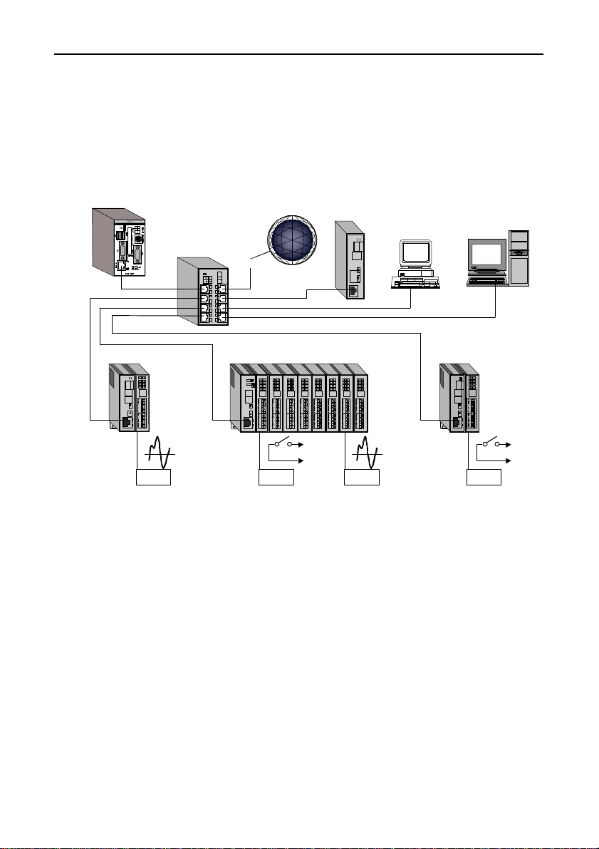
Multiple I/O Controller Units and Monitoring & Control Server can
be installed on the same network. In this manner, when connected to
an Monitoring & Control Server a host controller can input and
output signals to and from the devices that are connected to a
subordinate I/O Controller Unit.
Control Server
HUB
Device Device Device Device
Internet
Router
Unit
Local Terminal Office Terminal
I/O Controller UnitI/O Controller UnitI/O Controller Unit
Explanation of names
- Monitoring & Control Server:
This refers to the product SVR-MMF(FIT).
Data can be collected from I/O Assist Servers and I/O controllers
connected to the network as well as from connected device
modules.
The collected data can be displayed graphically by the monitoring
function. Also, the internal programming function allows
monitoring to be customized easily to suit the application by, for
example, outputting alarms when upper or lower limits are
exceeded or sending notification at fixed time intervals.
The collected data can be stored on the unit’s CompactFlash card
and sent to other network hosts using e-mail or FTP.
SVR-MMF(FIT)2
Page 16

Introduction
- I/O Assist Server Unit:
The I/O Assist Server Unit supports the management function that
enables it to collect data from, and set data to, I/O Controller Units
that belong to the same group as the Group ID that is set by using
the Group ID switches of the SVR-IOA(FIT) ("Assist Server"),
which is a CONTEC product. Group IDs can be set in a range of 0
to 7.
By connecting local terminals and office terminals by means of a
Web browser, it is possible to monitor the status of the devices that
are connected to an I/O Controller Unit.
- I/O Controller Unit:
The I/O Controller Unit is a general term that refers to any
combination of this product, the CPU-CA10(FIT), with device
modules.
Each device contains a Group ID SW and a Unit ID SW; these
switches must be set so that they are unique within the network.
The I/O Controller Unit transmits data collected from the devices
to the I/O Assist Server Unit that bears a specified Group ID.
Group IDs can be set in a range of 0 to 8, whereas Unit IDs are set
in a range of 0 to 7.
When the Group ID is set to 8, no data is transmitted to the I/O
Assist Server; instead, controls can be performed directly from a
terminal to the I/O Controller Unit.
The following device modules are available:
an 8-point digital input, an 8-point digital output module
(DIO-8/8(FIT)), a 16-point digital input module (DI-16(FIT)), a
16-point digital output module (DO-16(FIT)), an 8-point input
analog/digital converter module (ADI12-8(FIT)), a 4-point output
digital/analog converter module (DAI12-4(FIT)), and a 2-point
input counter module (CNT24-2(FIT)).
Further details on this topic may be found in the respective device
module manuals.
- HUB:
This is a line concentration device that is used when a LAN is
constructed using twisted-pair cables.
The F&eIT series includes an 8-port switching HUB unit
(SH-8008(FIT)) that is equipped with a DIN rail mounting
mechanism.
SVR-MMF(FIT) 3
Page 17

Introduction
Limited One-Year Warranty
CONTEC Interface boards are warranted by CONTEC Co., LTD. to
be free from defects in material and workmanship for up to one year
from the date of purchase by the original purchaser.
Repair will be free of charge only when this device is returned
freight prepaid with a copy of the original invoice and a Return
Merchandise Authorization to the distributor or the CONTEC group
office, from which it was purchased.
This warranty is not applicable for scratches or normal wear, but
only for the electronic circuitry and original products.
The warranty is not applicable if the device has been tampered with
or damaged through abuse, mistreatment, neglect, or unreasonable
use, or if the original invoice is not included, in which case repairs
will be considered beyond the warranty policy.
How to Obtain Service
For replacement or repair, return the device freight prepaid, with a
copy of the original invoice. Please obtain a Return Merchandise
Authorization Number (RMA) from the CONTEC group office
where you purchased before returning any product.
* No product will be accepted by CONTEC group without the
RMA number.
Liability
The obligation of the warrantor is solely to repair or replace the product.
In no event will the warrantor be liable for any incidental or
consequential damages due to such defect or consequences that arise
from inexperienced usage, misuse, or malfunction of this device.
SVR-MMF(FIT)4
Page 18

Handling Precautions
Take the following precautions when handling this product.
- Do not use or store the equipment in a hot or cold place, or a place
that is subject to severe temperature changes.
Examples: - Under direct sunlight
- Near a heat source
- Do not use or store the equipment in a place that is subject to
extreme humidity or dust. It will be extremely dangerous to use
the equipment when its interior is contaminated with water or
liquid, or conducting debris. When using the equipment in an
environment that is subject to water or conducting debris,
consideration should be given to the installation of a control panel
with a structure that keeps dust out.
- Do not use or store the equipment in a place that is subject to
shock or vibrations.
- Do not use or store the product near equipment generating a strong
magnetic field or radio waves.
- Do not use or store the equipment in air with diffused chemicals or
in an environment in which the equipment can come into contact
with chemicals.
- When attaching or detaching a module or a connector, please be
sure that the power cable for the system is unplugged from the
outlet.
- Do not modify the unit. CONTEC will bear no responsibility for
any problems, etc., resulting from modifying this unit.
- If you notice any malfunction or abnormal conditions (such or a
strange odor or overheating), please unplug the power cord and
consult either CONTEC's Information Center or the dealer from
whom the system was purchased.
Introduction
Notes on Handling This System
- To clean the SVR-MMF(FIT), gently wipe it with a soft cloth
soaked with water or a neutral detergent. Do not use benzene, a
thinner, or other volatile solvents as they can cause the coating to
discolor or peel off.
- Life of the components
Battery … A primary lithium battery is used to back up the
internal clock/calendar and the CMOS RAM. When
the power is not drawn and the battery is stored at
25°C, it will last over 10 years.
SVR-MMF(FIT) 5
Page 19

Introduction
* The supply items can be replaced in the same manner as the repair
About the Manual
This manual consists of the following chapters :
Chapter 1 Introduction
Chapter 2 Overview
Chapter 3 Function of the Various Components
Chapter 4 Hardware Setup
Chapter 5 System Setup
Chapter 6 Creation and Display of a Monitoring Screen
of the system (chargeable).
Explains the product specifications and system
configuration.
Explains each connector on the unit.
Explains how the units are to be installed and
connected for setup.
Explains how to set the IP address and configure the
system.
Explains the components and settings that can be used
on the monitoring screen.
Chapter 7 Creation and a Display of a Monitoring Task
Explains how to create applications for access to the
various devices, and the specific functions that are
available for applications development.
Chapter 8 Troubleshooting
Explains troubleshooting procedures.
Chapter 9 Appendix
Provides product specifications, describes the F&eIT
protocol that provides access to the F&eIT series, and
explains the virtual address map that is provided on the
system.
SVR-MMF(FIT)6
Page 20

2. Overview
Specifications
Table 2.1. Functional Specifications
CPU MachZ 120MHz (ZF Micro Devices)
Chip Set Built-in MachZ (ZF Micro Devices) CPU
Memory L2 Cache 512Kbyte PB-SRAM
Main Memory 144 pin Micro-DIMM Socket×1
BIOS ROM 128KB E0000h to FFFFFh (Phonix)
Video Controller 69000 (Chips & Technologies)
Video RAM 2Mbyte
Video BIOS 44Kbyte (C0000h to CAFFFh) or 32Kbyte (C0000h to C7FFFh)
CRT I/F 15 pin HD-SUB connector
Serial I/F RS-232C(generic): 1ch 9 pin D-SUB connector
LAN I/F Ethernet 100BASE-TX/10BASE-T RJ-45 connector
Controller Intel 82559
USB I/F 2ch (Not used)
Keyboard I/F PC/AT keyboard-compatible (6 pins, MINI DIN connector)
Mouse I/F PS/2 type mouse (6 pins, MINI DIN connector)
F&eIT I/F F&eIT series module connectivity
Watchdog timer function 2sec(Max.) (Output to either RESET or NMI, depending on time-up)
CompactFlash Slot TYPE I×1
RTC/CMOS Life of lithium backup battery: 10 yr. minimum (25°C)
Input power
Power
supply
External dimensions (mm) 52.4(W)×64.7(D)×94.0(H)
Weight 200g
voltage
Max. power
consumption
Overview
SVR-MMF(FIT)Model
Standard provides 64Mbyte
640×480/800×600 (16,770,000 colors), 1024×768 (65,536 colors ),
1280×1024 (256 colors)
(When using POW-DD10 power supply unit, the total power for externally
connected units . Should not exceed 1.5 A)
Accuracy of realtime clock: less than 3 min./month
5VDC ±5%
7.5W
SVR-MMF(FIT) 7
Page 21

Overview
Table 2.2. Installation Environment
Parameter Requirement description
Operating temperature 0 to 50°C
Storage temperature -10 to 60°C
Humidity 10 to 90%RH (No condensation)
Floating dust particles Not to be excessive
Corrosive gases None
Line-Noise
resistance
Vibration
resistance
Impact resistance
Grounding Class D grounding (previous class 3 grounding)
Line-noise *1 AC line/2kV, Signal line/1kV (IEC1000-4-4Level 3, EN61000-4-4Level 3)
Static electricity
resistance
Sweep
resistance
Contact discharge/4kV (IEC1000-4-2Level 2, EN61000-4-2Level 2)
Atmospheric discharge/8kV (IEC1000-4-2Level 3, EN61000-4-2Level 3)
10 to 57Hz/semi-amplitude 0.15mm, 57 to 150Hz/2.0G
80 minutes each in X, Y, and Z directions
(JIS C0040-compliant, IEC68-2-6-compliant)
15G, half-sine shock for 11ms in X, Y, and Z directions
(JIS C004-compliant, IEC68-2-27-compliant)
SVR-MMF(FIT)8
Page 22

System Configuration
Example of System Configuration
Overview
POW-DD10
Network
MODEM
Figure 2.1. System Configuration Diagram
COM-2(FIT)
ADI12-8(FIT)
DIO-8/8(FIT)
SVR-MMF(FIT) 9
Page 23

Overview
External Dimensions
SVR-MMF(FIT)
(1.2)
(8.0)
94
52.4
6.0 64.7 4.0 [mm]
Figure 2.2. SVR-MMF(FIT) External Dimensions
SVR-MMF(FIT)10
Page 24

Functions of the Various Components
3. Functions of the Various Components
Nomenclature
CompactFlash
WOL
USB
VGA
10/100BASE-TX
Power
KEYBOARD
/MOUSE
COM
RESET SW
SHUT DOWN
SW
Figure 3.1. Nomenclature
Table 3.1. Functions of the Various Parts
Name Function
Keyboard/MOUSE Keyboard/Mouse connector (MINI-DIN 6-pin) 12
COM Serial port connector (D-SUB 9-pin) 13
VGA CRT connector (HD-SUB 15-pin) 14
CompactFlash Compact FLASH insertion connector 14
RUN Status display LED 15
STATUS Status display LED 15
CF Compact FLASH access verification LED 15
SHUT DOWN SW SHUT DOWN 15
RESET SW Resets the CPU.
USB USB connector 15
10/100BASE-TX RJ-45 connector 16
WOL Not used
POWER Power supply connector
Expansion bus FactoryIT series connector
(MC1, 5/3-G-3, 5 PHOENIX CONTACT)
(0.6mm pitch, 80-pin (FX-8C series, HIROSE))
Expansion bus
Page
17
SVR-MMF(FIT) 11
Page 25

Functions of the Various Components
Keyboard/Mouse Interface
The system is equipped with a keyboard/mouse connector.
The name of the connector is KEY/MOUSE (MINI-DIN 6P).
Table 3.2. Keyboard/Mouse Connector
Connector type TCS7910-16-201 (Hoshiden) or equivalent
Pin No.
1
2
3
4
6
4
2
Signal
+KBD DATA
+MOUSE DATA
GND
+5.0V DC
Pin No.
5
6
SHIELD
---
5
3
1
Signal
+KBD CLK
+MOUSE CLK
GND
SVR-MMF(FIT)12
Page 26
Serial Port Interface
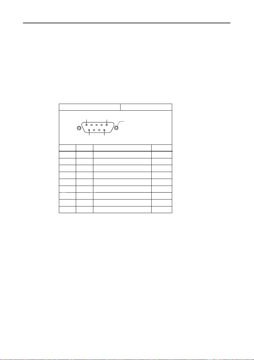
RS-232C port (COM)
The system is equipped with one RS-232C-compliant serial port
connector (serial port A: COM).
Note!
The serial port of this module is not supporting RI signal.
Table 3.3. Serial Port Connector
Connector used on the system unit D-SUB 9 core (MALE)
1 5
6
Pin No.
Signal
1
CD
2
RD
3
TD
4
DTR
5
GND
6
DSR
7
RTS
8
CTS
9
RI
Functions of the Various Components
No.4-40UNC
inch screw
9
Meaning
Carrier detect
Received data
Transmitted data
Data terminal ready
Signal ground
Dataset ready
Request to send
Clear to send
Ring indicator (Not connected)
Direction
Input
Input
Output
Output
-----
Input
Output
Input
-----
SVR-MMF(FIT) 13
Page 27

Functions of the Various Components
CRT Interface
The system is equipped with a connector for the CRT. The name of
the connector is VGA(HD-SUB 15P).
Table 3.4. CRT Connector
Connector type
10
Pin No.
1
2
3
4
5
6
7
8
15pin HD-SUB (MALE)
1
5
11
15
Signal
RED
GREEN
BLUE
N.C.
GND
GND
GND
GND
CompactFlash Slot
Pin No.
9
10
11
12
13
14
15
6
No.4-40UNC
inch screw
Signal
N.C.
GND
N.C.
N.C.
HSYNC
VSYNC
N.C.
The system is equipped with a slot for CompactFlash-compliant
CompactFlash cards [TYPE I x 1 size], which is available for
memory cards only. A CompactFlash card loaded with monitoring
and control tools is inserted in the unit.
Power supply for the card
Available card voltages and current values for each slot are listed
below:
Table 3.5. Power Supply for the Card
Voltage Current (Max.)
+5V 500mA/Slot
+3.3V Not supplied
+12V Not supplied
SVR-MMF(FIT)14
Page 28

Functions of the Various Components
RUN LED
Blinks while the unit is running.
The LED stops blinking and remains illuminated when
SHUTDOWN completes after you press the SHUTDOWN switch.
Wait until the LED stops blinking before turning off the power.
STATUS LED
Illuminates when an error occurs.
CF LED
This light comes on when the CompactFlash is accessed.
SHUTDOWN SW
Used to shutdown the system. The RUN LED illuminates when the
power is able to be turned off.
USB Port
It cannot be used.
SVR-MMF(FIT) 15
Page 29

Functions of the Various Components
Ethernet
The SVR-MMF(FIT) is equipped with a Fast-Ethernet card.
- Network mode: 100BASE-TX/10BASE-T
- Transmission rate * : 100M/10M bps
- Max. network path length: 100m/segment
- Controller: 82559(Intel)
* Operation at 100 Mbps requires a Category 5 cable.
Table 3.6. Ethernet Connector
Network status display LED:
LINK/ACT: Normal connection, data send/receive displayed
SPEED: 10M/100M operation indicator
SVR-MMF(FIT)16
Page 30
POWER
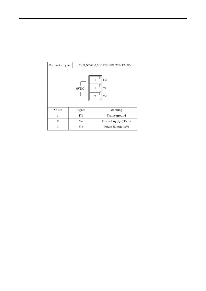
This is a power supply connector
- Power supply: 5.0V±5%
Table 3.7. Power Supply Connector
Available connectors (included):
MC1,5/3-ST-3,5(PHOENIX CONTACT)
Functions of the Various Components
SVR-MMF(FIT) 17
Page 31

Functions of the Various Components
SVR-MMF(FIT)18
Page 32

4. Hardware Setup
Getting Started
Follow the following procedures to set up the SVR-MMF(FIT):
STEP1 Connecting the F&eIT series module
By referring to this chapter connects the F&eIT series
module to the SVR-MMF(FIT). When using the
SVR-MMF(FIT) on a standalone basis, go to STEP2.
STEP2 Connecting the cables
Connect the LAN cable and any modem or other external
device cables to the SVR-MMF(FIT).
STEP3 Turning on the power
After re-checking that STEPS 1 to 2 have been correctly
performed, turn on the power. If something goes wrong
after the power is turned on, immediately turn off the
power and make sure that the system is correctly set up.
Hardware Setup
SVR-MMF(FIT) 19
Page 33
Hardware Setup
Mounting the Module
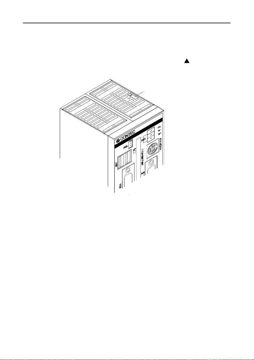
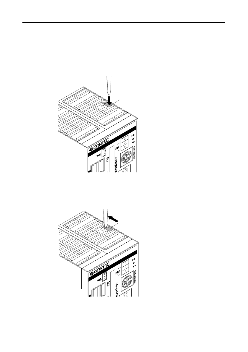
Stack Connection Locking Devices
The module contains connecting locking devices ( mark, two
units at the top and bottom).
Locking device
SVR-MMF(FIT)20
Page 34
Hardware Setup
How the stack connection locking device works
- Locking
Push the pawl of the locking device with a tool that has a slender
tip downward from above to open the spring for the locking
device (the groove moves toward you).
Locking device
- Unlocking
Push the groove of the locking device with a tool that has a slender
tip in the direction of the arrow until the device is locked.
Locking device
SVR-MMF(FIT) 21
Page 35
Hardware Setup
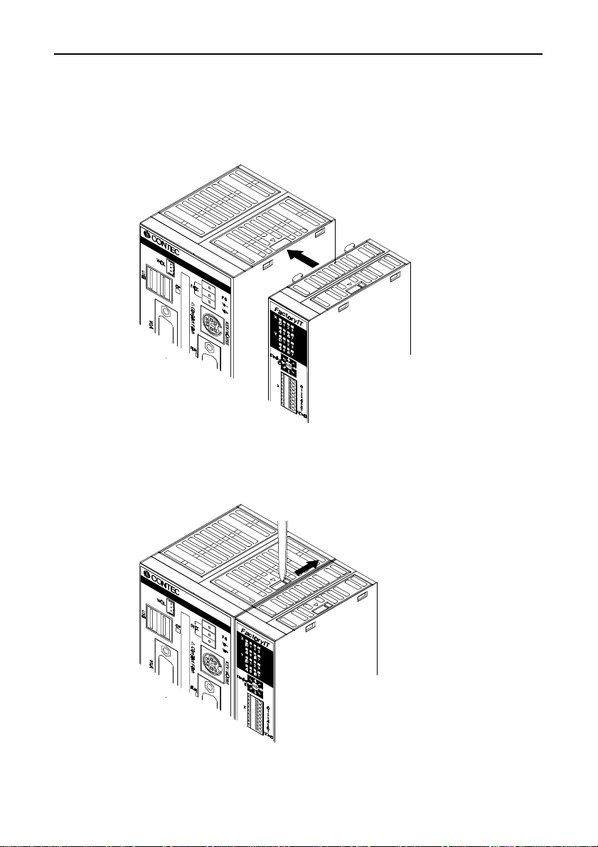
Connecting the module
Inserting the stack hook by aligning it with the hook insertion inlet
for the other device automatically locks the module. (If a stack
connector protective cover is attached, the connection operation
should be performed after the cover is removed.)
Removing the module
Unlock the locking device at the top and the bottom. Remove the
connected module from the hook.
SVR-MMF(FIT)22
Page 36
Mounting on a DIN Rail
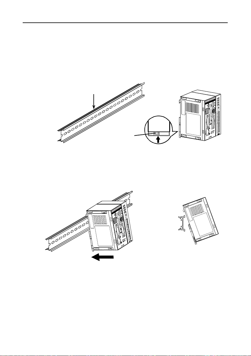
Mounting procedure
(1) Pushing the fixing hook with a flat-blade screwdriver renders it
into a lock-enabled condition (this should be done on all
connected modules).
35mm DIN rail
Press here
to lift the fixing hook.
Figure 4.1. Mounting on a DIN Rail < 1 / 3 >
(2) Hook the unit (an object consisting of a controller and a
module) from the upper part of the DIN rail, and press the
lower part of the unit onto the DIN rail.
Hardware Setup
Figure 4.1. Mounting on a DIN Rail < 2 / 3 >
SVR-MMF(FIT) 23
Side view
Page 37
Hardware Setup
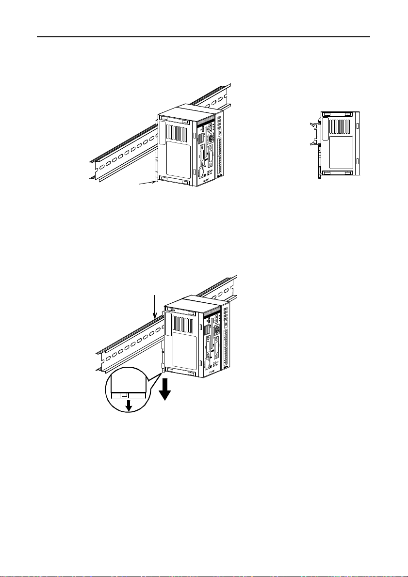
(3) The fixing hook is automatically locked, and the module can be
mounted in one-touch.
fixing hook
Side view
Figure 4.1. Mounting on a DIN Rail < 3 / 3 >
Removal procedure
(1) Lower the fixing hook for the unit to unlock it. (This operation
should be performed on all connected modules.)
35mm DIN rail
Figure 4.2. Removing the Module from the DIN Rail
< 1 / 3 >
SVR-MMF(FIT)24
Page 38
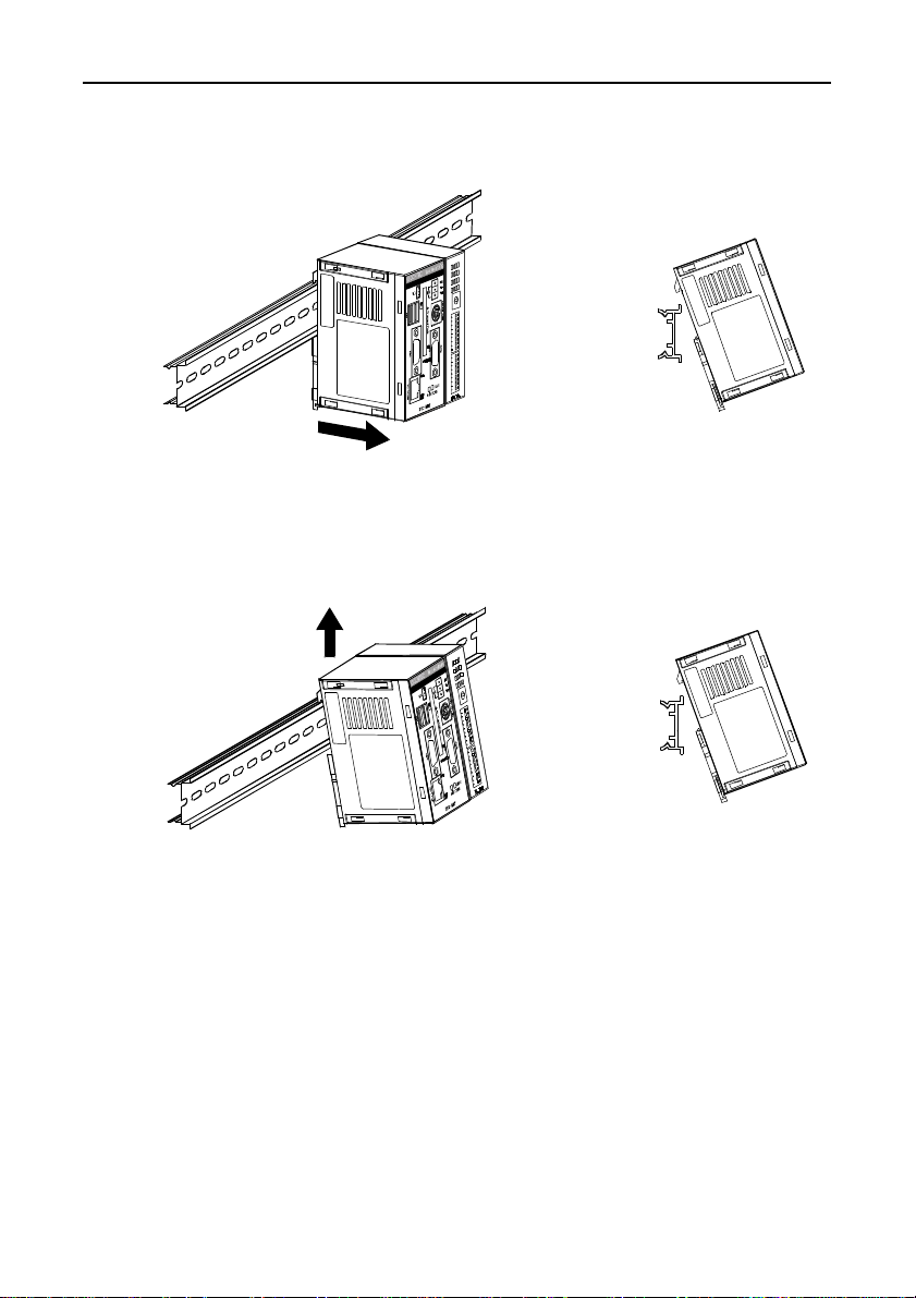
Hardware Setup
(2) With the fixing hook unlocked, pull the lower part of the unit
toward you.
Side view
Figure 4.2. Removing the Module from the DIN Rail
< 2 / 3 >
(3) By lifting the unit, you can easily remove it from the DIN rail.
Note!
Side view
Figure 4.2. Removing the Module from the DIN Rail
< 3 / 3 >
Any operation involving the disconnection of modules in a unit
(in which multiple modules are connected) that is attached to a DIN
rail should be performed after the unit is removed from the DIN rail.
SVR-MMF(FIT) 25
Page 39
Hardware Setup
Connection Method
Supplying the Power to the Controller Module
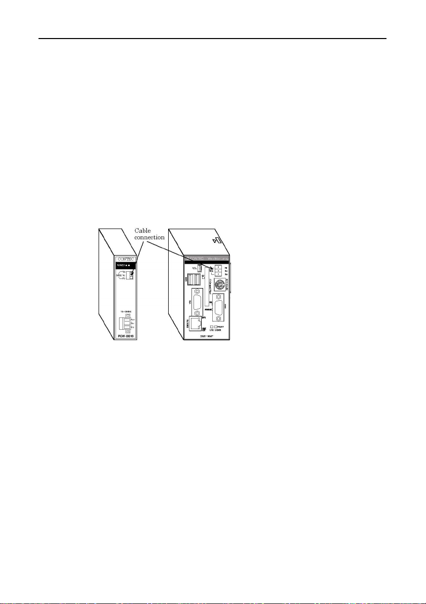
(1) The DC-DC power supply unit and the controller module can
be cable-connected using the detachable connector that is
provided on either the unit face or module face. Use a cable no
longer than 50cm (AWG24 to 16). (No longer than 20cm for
AWG28 and no longer than 35cm for AWG26). (compatible
cables: AWG28 to 16).
Note!
The power for the device module is supplied from the stack
connector.
Figure 4.3. Connecting the Controller Module to the
DC-DC Power Supply Unit
SVR-MMF(FIT)26
Page 40
Installation Conditions
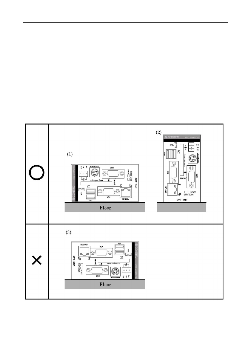
The system can be installed in either orientation (1) or (2).
Orientation (3), which does not lend itself to heat dissipation, should
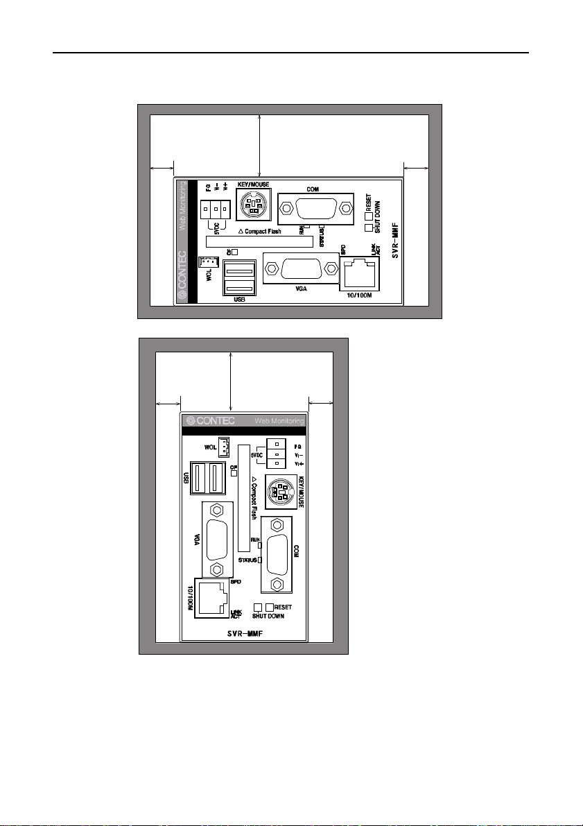
be avoided. A minimum clearance of 50 mm at the top and 10 mm
on the sides should be provided between the system unit and any
surrounding objects. If using orientation (1), do not connect any
other modules. If using orientation (2), other modules may be
connected but ensure a clearance on the bottom side of at least
20mm.
Installation orientation (stand-alone unit)
Hardware Setup
Figure 4.4. Installation Orientation
SVR-MMF(FIT) 27
Page 41
Hardware Setup
Spacing between the system unit and any surrounding objects
10mm min.
(side)
10mm min.
(side)
50mm min. (top)
50mm min.
(top)
10mm min.
(side)
10mm min.
(side)
Figure 4.5. Spacing between the System Unit and Any
Surrounding Objects
SVR-MMF(FIT)28
Page 42

5. System Setup
Setting Procedure
The IP address set for the Monitoring & Control Server must not be
already used by an I/O Assist Server, I/O controller, or other unit.
The default factory settings are IP address = “10.1.1.1” and network
mask = “255.0.0.0”.
(1) Connect the power and network cables to the Monitoring &
Control Server Unit.
(2) The Monitoring & Control Server searches for any I/O Assist
Servers and I/O controllers and starts collecting input data
automatically.
(3) By connecting to the Monitoring & Control Server Unit from
the browser running on the host controller, you can view the
input data.
Set the IP address and the network mask so that the host
controller belongs to the same network as the Monitoring &
Control Server Unit.
System Setup
(4) For procedures on how to view input data using a browser, see
the section entitled "Verifying the Operation".
SVR-MMF(FIT) 29
Page 43
System Setup
Verifying the Operation
The Monitoring & Control Server continuously reads the latest data
from the devices connected to the I/O Assist Server and I/O
Controller Units on the same network.
Connecting from the host computer to the Assist Server using a
browser to create and view a monitoring screen.
State Check from a Browser
Operation procedure
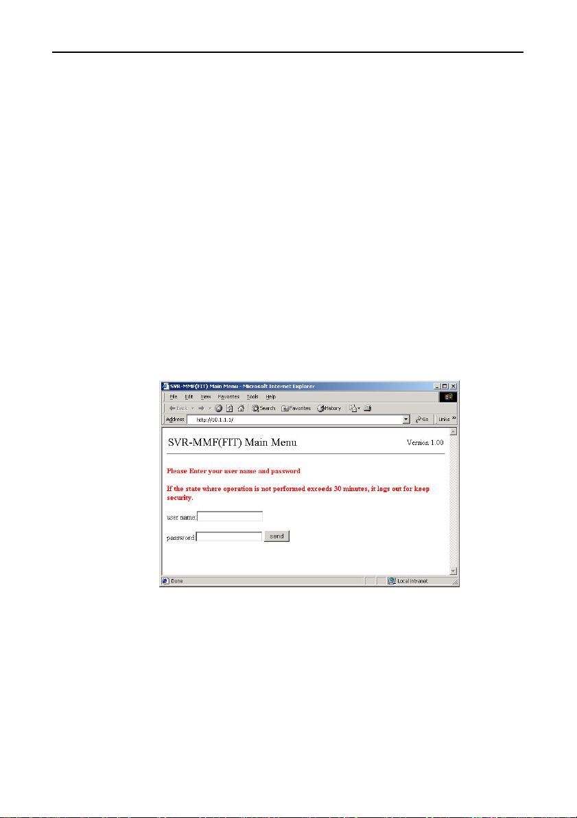
(1) Start the browser. In the browser ’s address field, enter the IP
address that was set on the Monitoring & Control Server Unit.
Example: For an IP address 10.1.1.1, enter the following:
"http://10.1.1.1/".
(2) The screen of "Main Menu" is displayed.
Figure 5.1. Password Input
The user name "mmf" password "mmf" is registered at the time of
shipment.
Use standard lower case characters.
SVR-MMF(FIT)30
Page 44
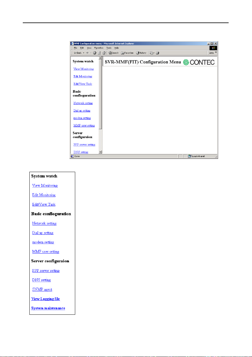
(3) A menu is displayed.
Figure 5.2. Whole Screen
System watch
- Used to edit monitoring and execution tasks.
System Setup
Figure 5.3. Menu
Basic configuration
- Used to set network, dial-up, and other parameters.
Server configuration
- Used to setup the server function.
View Logging file
- Displays error information during operation.
System maintenance
- Used for backing up the setup data, etc.
SVR-MMF(FIT) 31
Page 45
System Setup
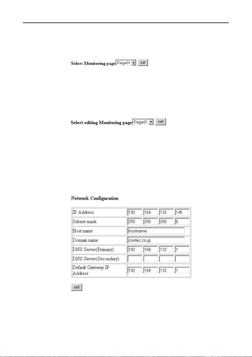
(4) Monitoring display
The monitoring screen appears.
See “Chapter 6 Creation and Display of a Monitoring Screen ”.
Figure 5.4. Monitoring Display
(5) Monitoring creation
The monitoring screen appears.
See “Chapter 6 Creation and Display of a Monitoring Screen”.
Figure 5.5. Monitoring Creation
(6) Task creation and a display
Click here to display the task edit screen.
See “Chapter 7 Creation and a Display of a Processing Task”.
(7) Network setup
Figure 5.6 Network Configuration
SVR-MMF(FIT)32
Page 46
System Setup
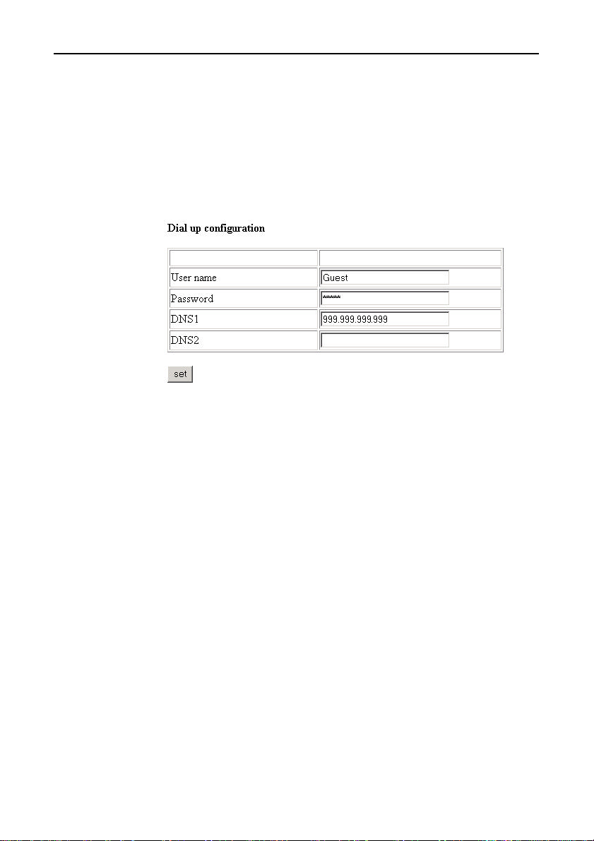
IP Address-Subnet mask:
Enter the IP address and subnet mask you wish to set for the
network port. The default factory settings are IP address =
“10.1.1.1” and subnet mask = “255.0.0.0”.
When finished, click [Set] to save the settings.
The new settings become active from the next time the unit is
restarted.
(8) Dial up configuration
Figure 5.7 Dial up Configuration
If connecting a modem to the COM port and dialing up to a provider,
enter the “User name” and “Password” issued by the provider.
If you need to specify a DNS, enter the IP address of the DNS.
Click [Set] when you have finished.
You do not need to enter these settings if not using the dial-up
function.
SVR-MMF(FIT) 33
Page 47
System Setup
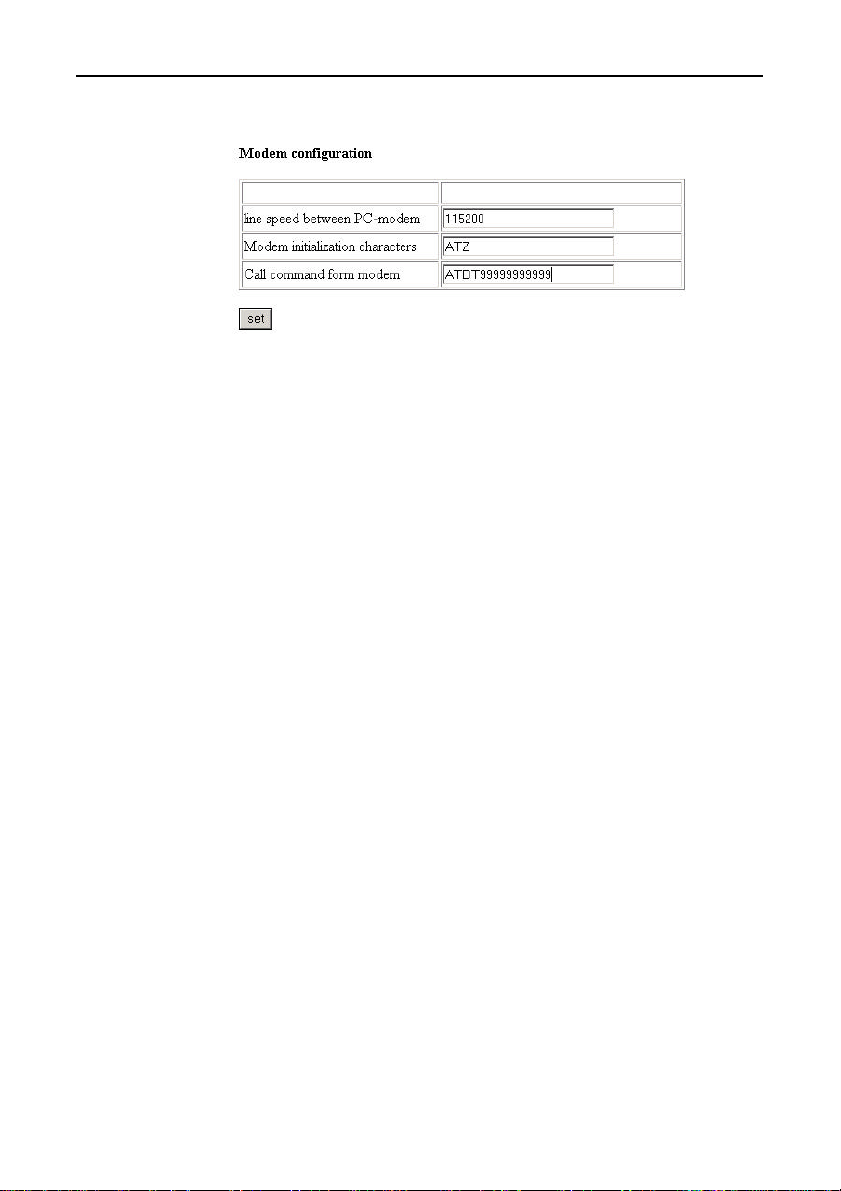
(9) Modem configuration
Figure 5.8. Modem Configuration
Set these parameters if connecting a modem to the COM port and
dialing up to a provider.
Line speed between PC-modem:
Enter the baud rate supported by the modem.
unit: bps
Modem initialization characters:
Set the modem initialization command. Refer to the modem’s
manual.
Call command form modem:
Enter ATDT if using a “tone dialing” line or ATPT if using a
“pulse dialing” line. Enter the provider’s telephone number after
ATDT.
Click [Set] when you have finished.
You do not need to enter these settings if not using the dial-up
function.
SVR-MMF(FIT)34
Page 48
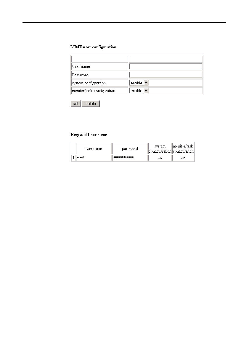
(10) MMF user configuration
Figure 5.9. MMF user Configuration
Figure 5.10. MMF User Configuration
(A Registered User Name)
System Setup
Register or delete the users able to access the setup screens (screens
described in this chapter) from the web.
The factory default settings are user name = “mmf”, password =
“mmf”.
For each user:
Specify whether changing the system configuration is “enabled”
or “disabled”.
Specify whether changing the monitor/task configuration is
“enabled” or “disabled”.
Click [Set] when you have finished.
Enter the user name and click [Delete] to delete a registered user.
SVR-MMF(FIT) 35
Page 49
System Setup
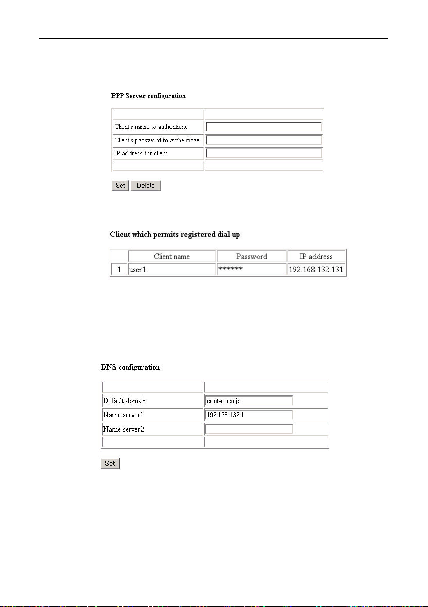
(11) PPP Server configuration
- PPP Server configuration
Figure 5.11. PPP Server Configuration
Figure 5.12. PPP Server Configuration
Enter the [Client name] and [Password] for permitting access to the
dial-up connection.
- DNS configuration
Figure 5.13. DNS Configuration
Specify the DNS to be used by the dial-up client.
SVR-MMF(FIT)36
Page 50
System Setup
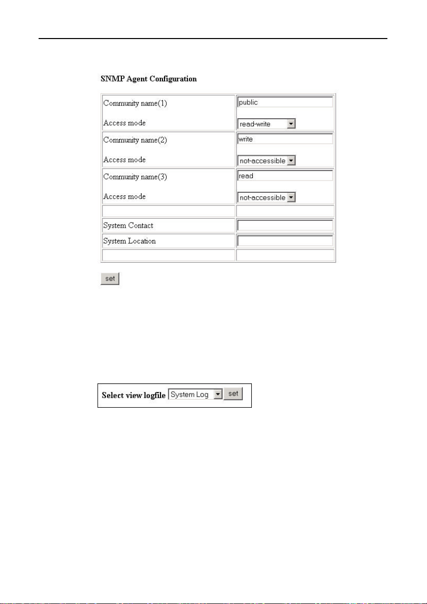
(12) SNMP Agent Configuration
Figure 5.14. SNMP Agent Configuration
Enter the information to be provided to SNMP.
Separate access permission can be specified for community names
(1), (2), and (3).
(13) View Logging file
Figure 5.15. View Logging File
Select one of the following log files:
- Message Log
- System Log
then click [Set] to display the file.
The logs are displayed in chronological order.
SVR-MMF(FIT) 37
Page 51
System Setup
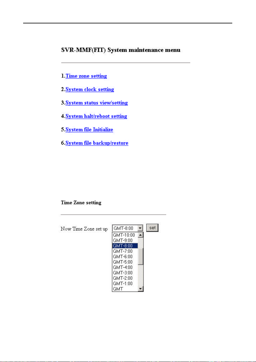
(14) System maintenance menu
Figure 5.16. System Maintenance Menu
Used for system maintenance and to backup and restore the settings.
(15) Time Zone setting
Figure 5.17. Time Zone Setting
Set the time zone where the unit is installed.
SVR-MMF(FIT)38
Page 52
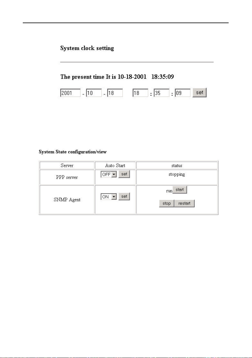
(16) System clock setting
Figure 5.18. System Clock Setting
Set the system time.
(17) System State configuration/view
System Setup
Figure 5.19. System State Configuration/View
Used to set and display the status of the server functions.
- PPP server : Server for accepting dial-up connections
- SNMP Agent : Server that responds to SNMP queries.
Only set Auto Start “ON” for the functions you intend to use.
SVR-MMF(FIT) 39
Page 53
System Setup
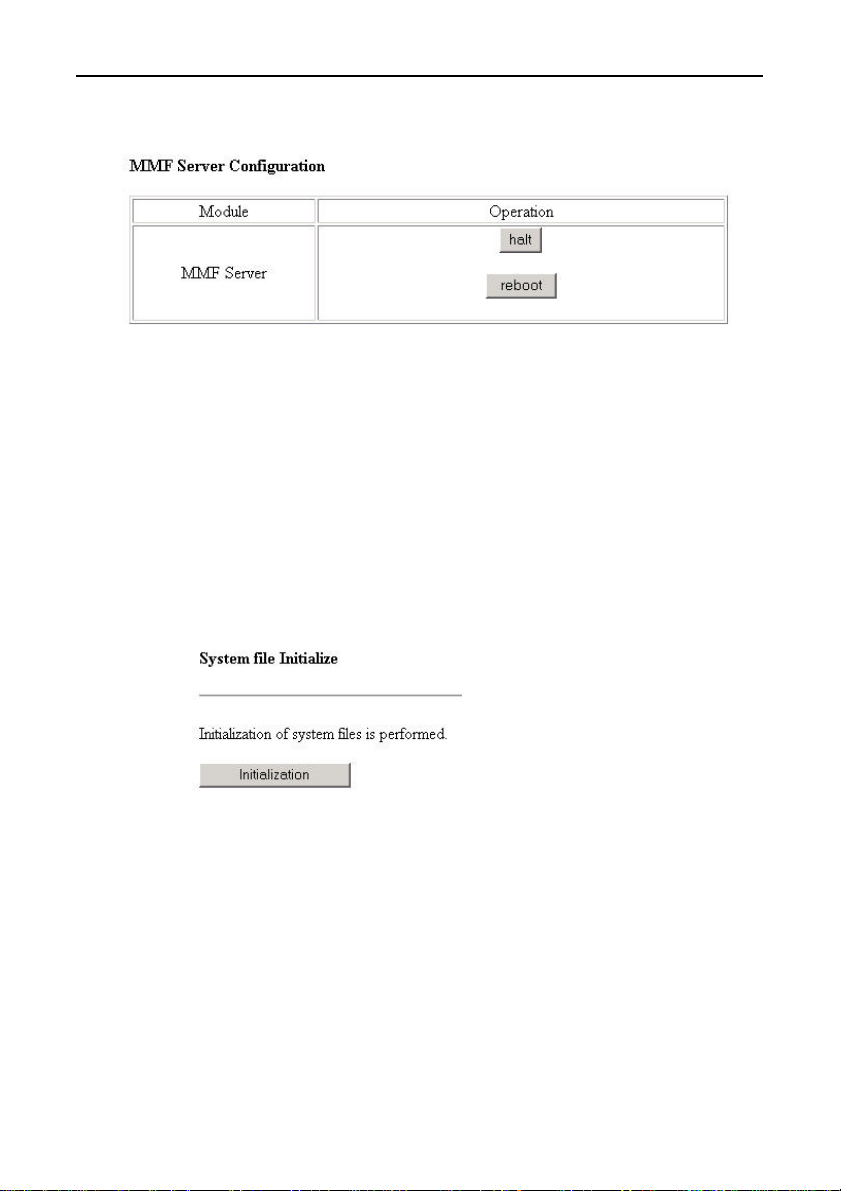
(18) MMF Server Configuration
Figure 5.20. MMF Server Configuration
To turn off the power, click [halt]. When the RUN LED stops
blinking and stays illuminated, it is safe to turn off the power.
After changing the settings, click [reboot] to apply the new settings.
This shuts down the system then restarts using the new settings.
Rebooting is also necessary to apply the settings in “(7) Network
setup” only.
(19) System file Initialize
Figure 5.21. System File Initialize
This restores all settings to their factory default values.
This also deletes any user-created monitoring screens or tasks.
SVR-MMF(FIT)40
Page 54
System Setup
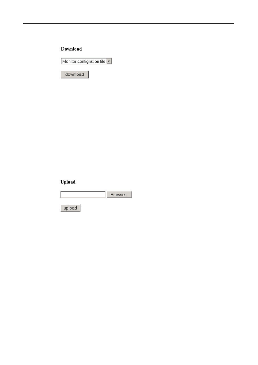
(20) System file backup/Restoration
Figure 5.22. System File Backup/ Restoration
You can make a backup of the setup data.
- Monitoring data: Setup data for created monitoring screens.
- Task data: Setup data for created tasks.
- Setup data: Setup data for Mail, Ftp, and File resources
used by tasks.
- MMF user data: The user registration data set in “(10) MMF
Select the data to backup then click [download].
user configuration”.
Figure 5.23. System File Restoration
You can load previously backed up data to restore the settings
Select the backup file to load, then click [upload] to transfer the file.
SVR-MMF(FIT) 41
Page 55

System Setup
SVR-MMF(FIT)42
Page 56
Creation and a Display of a Monitoring Screen
6. Creation and a Display of a Monitoring
Screen
By connecting to the Monitoring & Control Server from the host
computer using a browser, you can create and view a monitoring
screen.
Operation Procedure
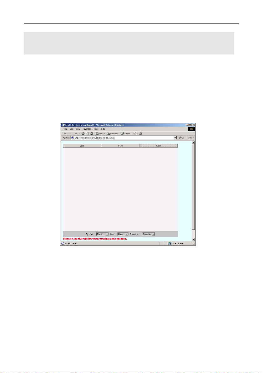
Clicking on page number button of [Data Monitoring (Calling
Applet)] brings up the following screen:
Figure 6.1. Menu
Menu bar functions:
Load: Loads and displays a previously saved page.
Save: Saves the monitoring screen that has been created.
Clear: Clears the current monitoring screen.
Fg Color: Selects the color in which the screen is to be drawn.
Item: Selects the component to be laid out.
Operation: Selects the specific operation to be performed.
SVR-MMF(FIT) 43
Page 57
Creation and a Display of a Monitoring Screen
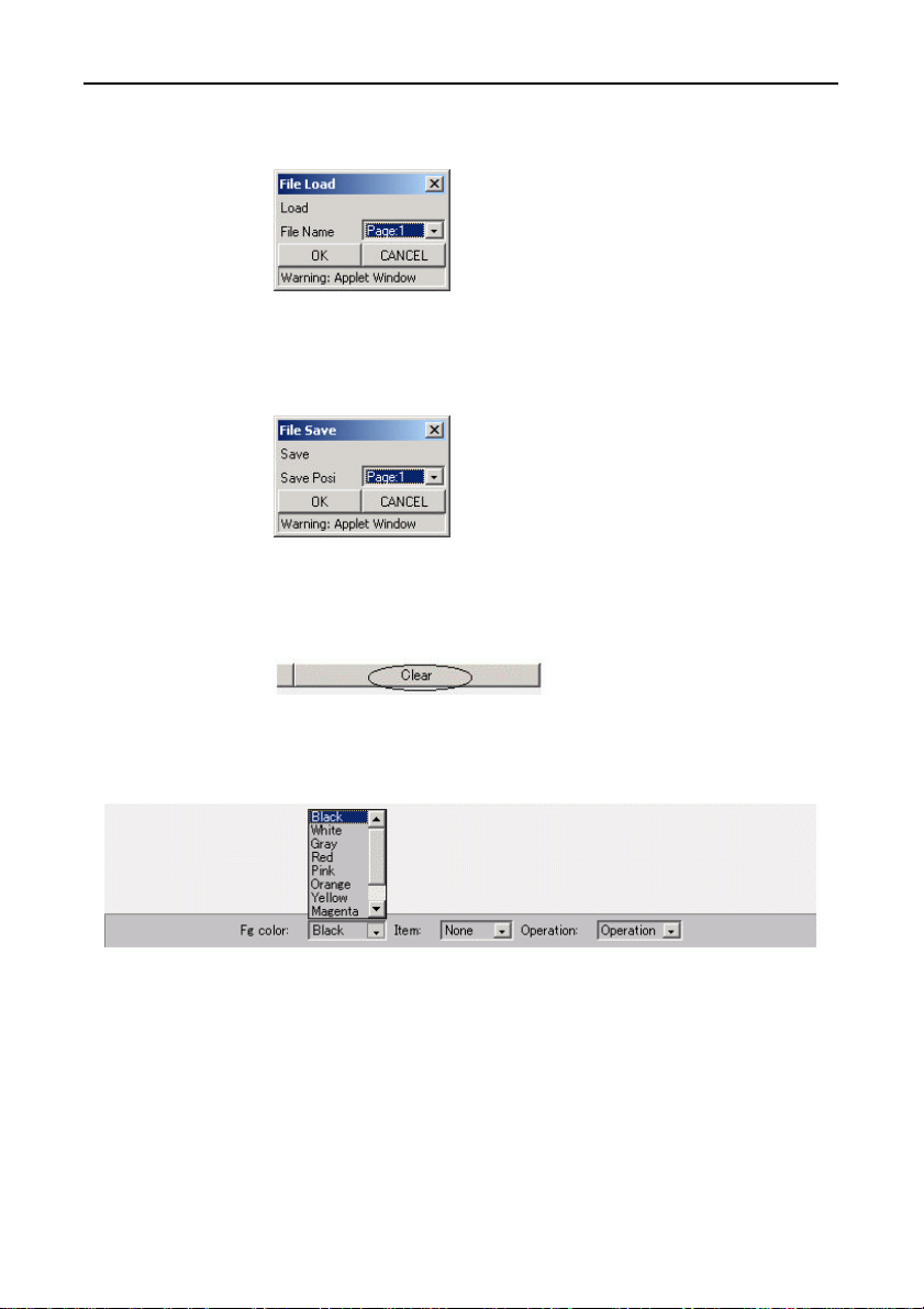
Load: Loads and displays a previously saved page.
Figure 6.2. File Load
Save: Saves the monitoring screen that has been created.
Figure 6.3. File Save
Clear: Clears the current monitoring screen.
Figure 6.4. Clear
Fg Color: Selects the color in which the screen is to be drawn.
Figure 6.5. Fg Color
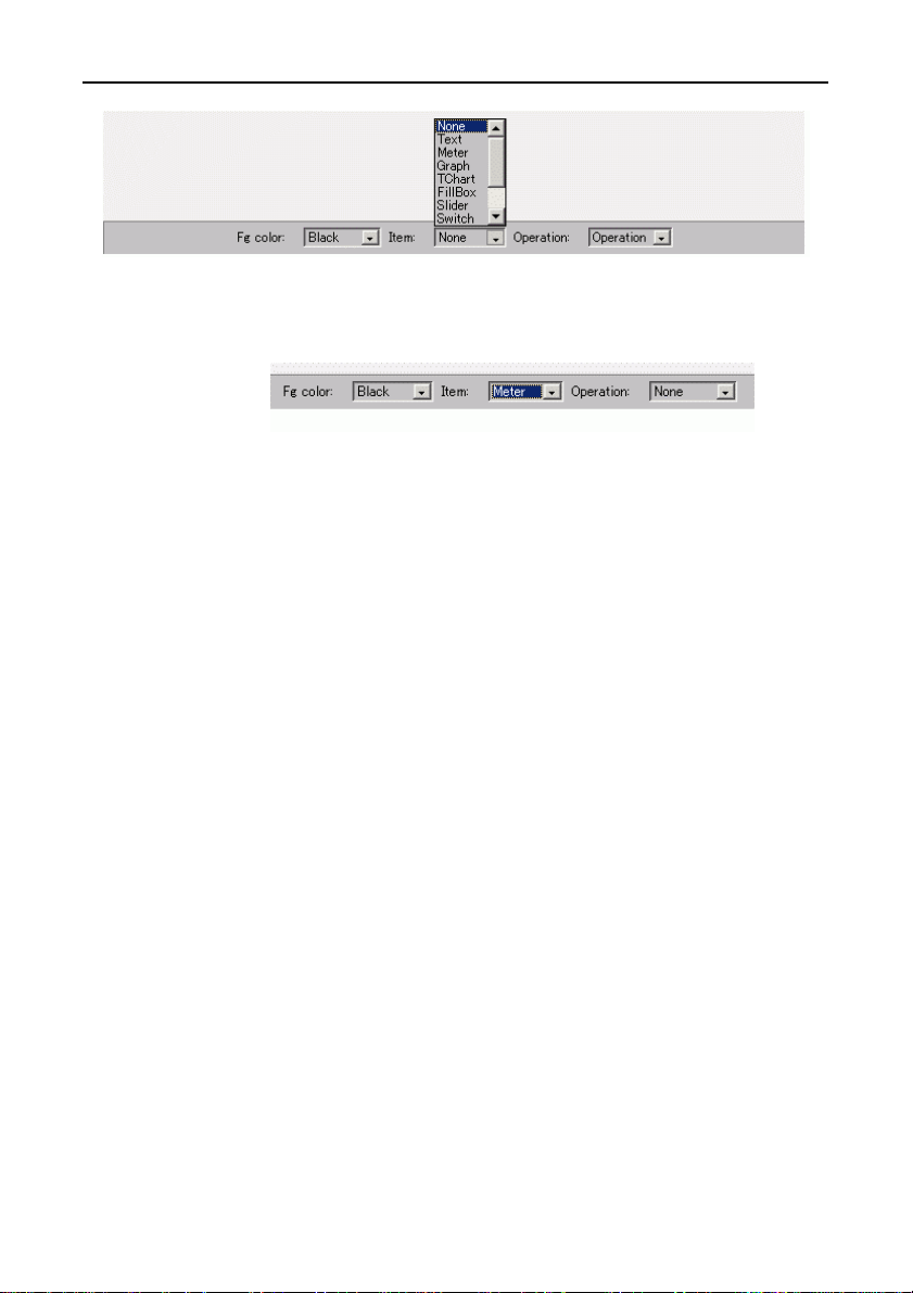
Item: Selects the component to be laid out.
SVR-MMF(FIT)44
Page 58
Creation and a Display of a Monitoring Screen
Figure 6.6. Item
Operation: Selects the specific operation to be performed.
Figure 6.7. Operation
SVR-MMF(FIT) 45
Page 59
Creation and a Display of a Monitoring Screen
Basic Operations
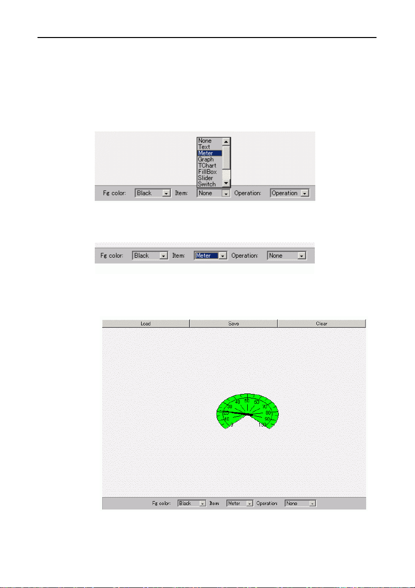
(1) Laying out a component
In [Item], select the desired component, and click on it on the
screen in order to lay it out.
Example: Laying out a [Meter]
Figure 6.8. Item
↓
Figure 6.9. Item Meter
Single-clicking on the screen displays the meter.
Figure 6.10. Meter
SVR-MMF(FIT)46
Page 60
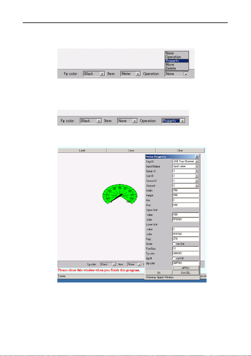
Creation and a Display of a Monitoring Screen
(2) In [Operation], select [Properties], and click on the component
to open the [Properties] box.
Figure 6.11. Operation
↓
Figure 6.12. Operation Property
Figure 6.13. Property
Each component to be laid out is associated with its own Unit ID,
Device ID, and Channel parameters for display purposes.
SVR-MMF(FIT) 47
Page 61
Creation and a Display of a Monitoring Screen
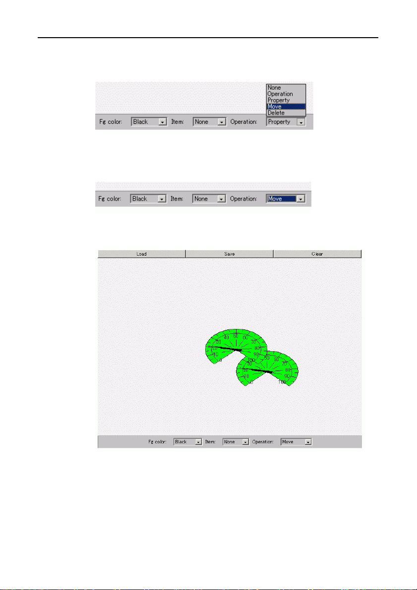
(3) You can also move a component by selecting [Move] in
[Operation].
Figure 6.14. Operation
↓
Figure 6.15. Operation Move
Figure 6.16. Move
By left-clicking the mouse on the component and dragging the
mouse, you can move the components. Releasing the mouse fixes
the component at the current mouse position.
SVR-MMF(FIT)48
Page 62
Creation and a Display of a Monitoring Screen
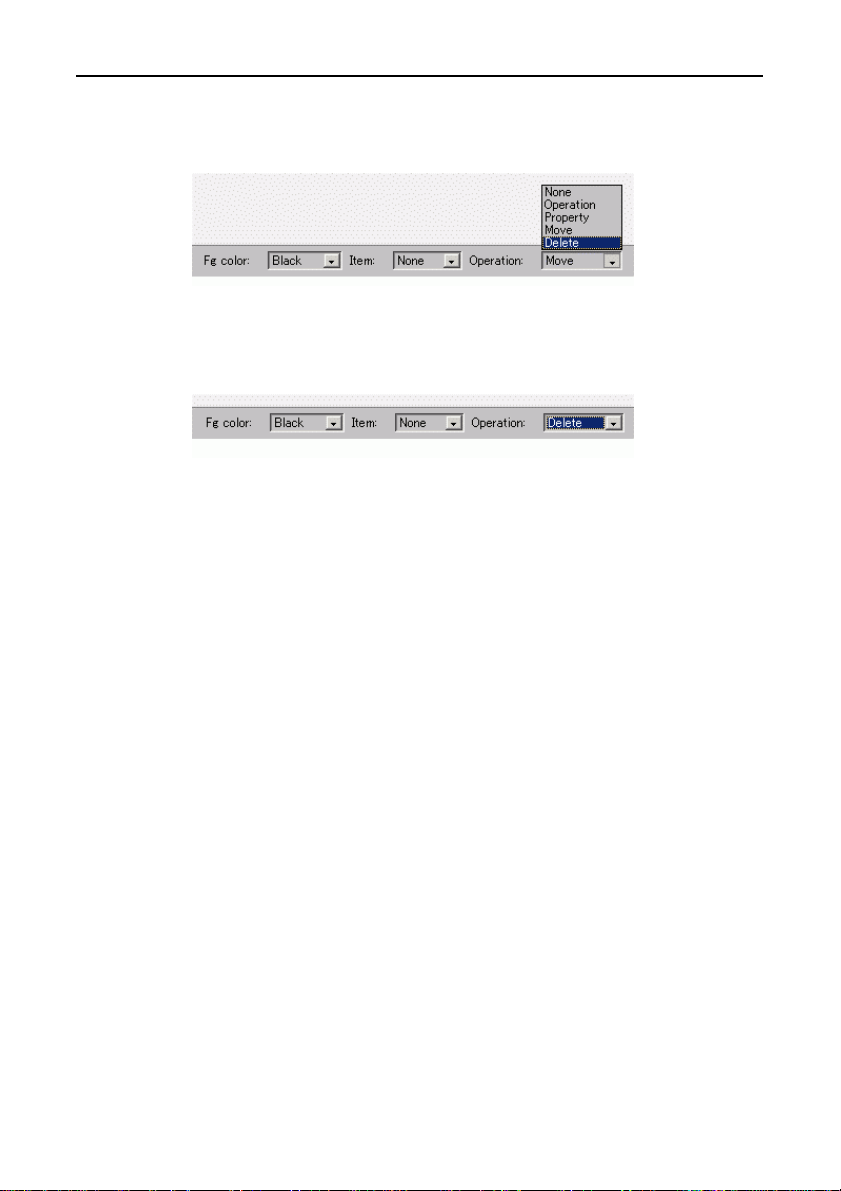
(4) You can delete a component by selecting [Delete] in
[Operation].
Figure 6.17. Operation
↓
Figure 6.18. Operation Delete
Left-clicking on the component deletes it.
(5) A monitoring screen can be created by laying out the various
components according to the procedures described above.
Once a monitoring screen is created, you can display a dialog
by selecting [Save] on the menu in order to save it on a desired
page.
You can bring up a previously saved page by selecting [Load]
on the menu to display a dialog and select the desired page.
SVR-MMF(FIT) 49
Page 63
Creation and a Display of a Monitoring Screen
Types of Available Components and Their
Overview
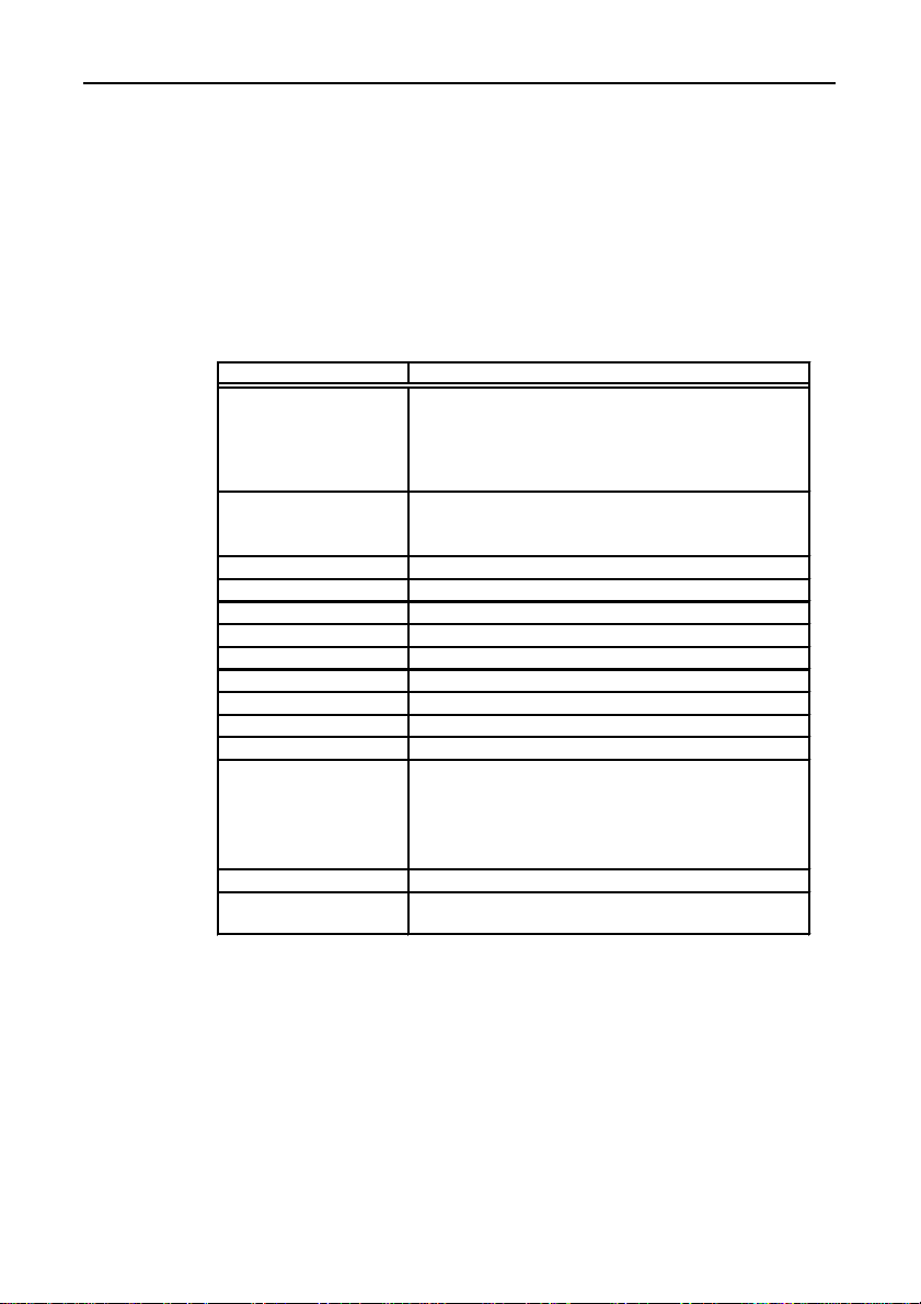
Components that can be selected from [Item] on the Menu bar are
described below.
Parameters that are common to the various components are also
explained below.
Table 6.1. Parameter List
DescriptionParameter
Tag ID Selects the item to display.
TAG00 to TAG99 display the values of the variables (TAG
numbers) used in tasks.
USE Raw Channel specifies a device channel. This is the
digital input value from the device.
Input/Output In terms of Input/Output, select [Output value] for displaying
Unit ID, Device ID, Channel Select the I/O module to be monitored.
Width Specify the width of the component.
Height Specify the height of the component.
Min Specify the minimum value to be displayed.
Max Specify the maximum value to be displayed.
Upper limit Specifies the upper limit display color.
Lower limit Specifies the lower limit display color.
Scale (not Set) Checking this item suppresses the Min/Max range scaling.
FontSize Specify the font size to be used in the component.
Fg color Specify the display color to be used.
Bg fill (not Fill) The component is not to be filled with the background color.
Bg color
values from an output-capable module.
The default is [Input value], which indicates an input value.
This parameter is specified in hexadecimal, where a group of
two digits, from left to right, indicates an RGB color, as follows:
000000: black; FFFFFF: white;
FF0000: red; 00FF00: green; 0000FF: blue.
Specify a background color in hexadecimal, using the same
conventions as in Fg color.
SVR-MMF(FIT)50
Page 64
Creation and a Display of a Monitoring Screen
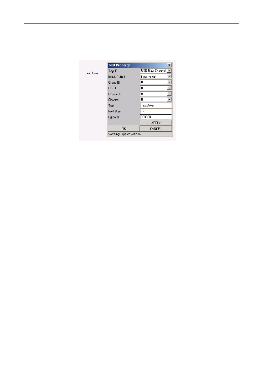
(1) Text: This is a component on which fixed text is displayed.
External view of Properties dialog box
the component
Figure 6.19. Text
Displays the fixed character string that is assigned to the [Text]
field.
The Font Size can be changed.
By specifying a Unit ID, a Device ID, a Channel, and [%d] in [Text],
you can display the input values in decimal.
Similarly, by specifying a Unit ID, a Device ID, a Channel, and [%x]
in [Text], you can display the input values in hexadecimal.
SVR-MMF(FIT) 51
Page 65
Creation and a Display of a Monitoring Screen
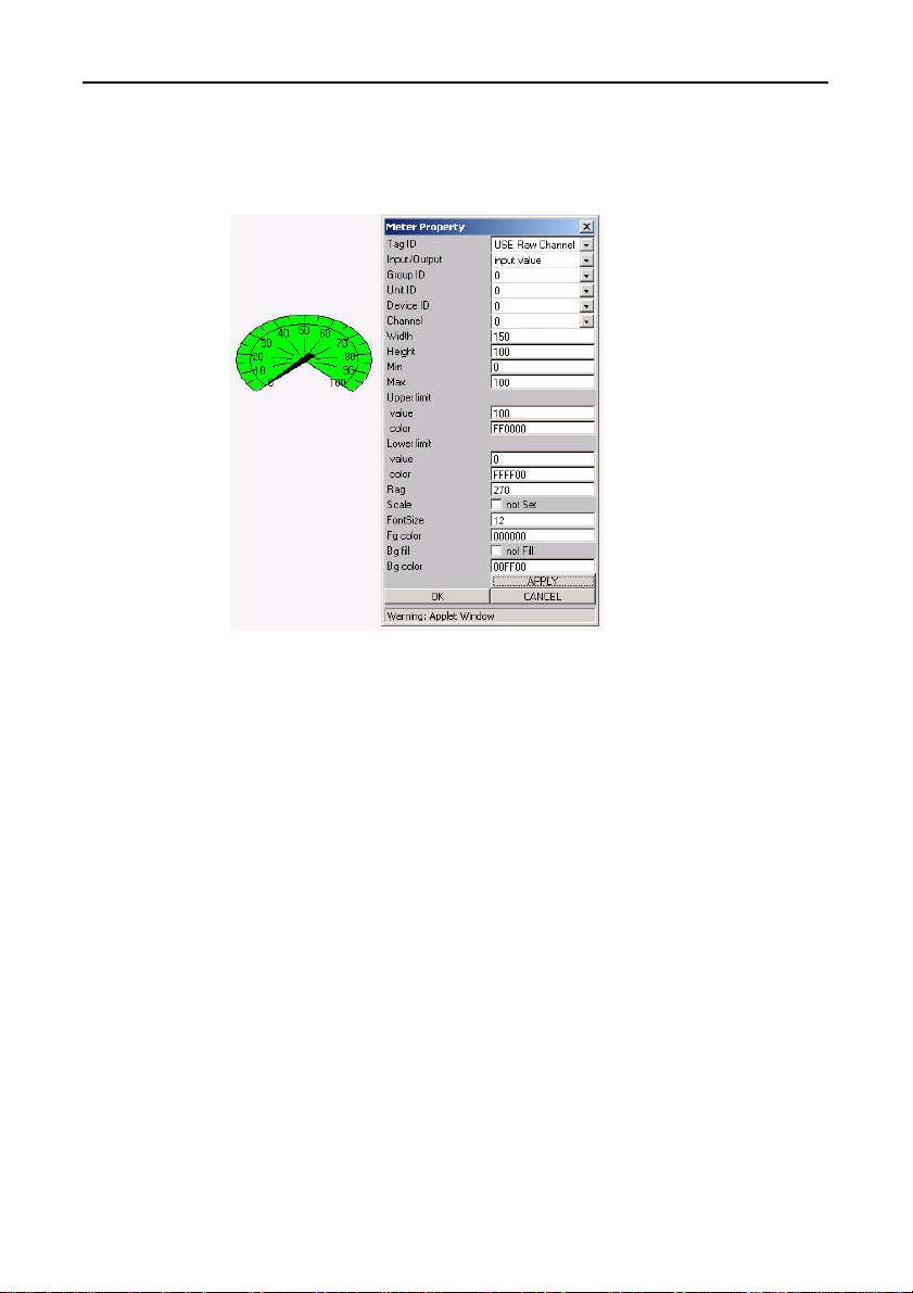
(2) Meter: Displays the [meter] data type.
External view of Properties dialog box
the component
Figure 6.20. Meter
- Rag: Specify an arc angle for a meter display in a range from 90
to 360.
SVR-MMF(FIT)52
Page 66
Creation and a Display of a Monitoring Screen
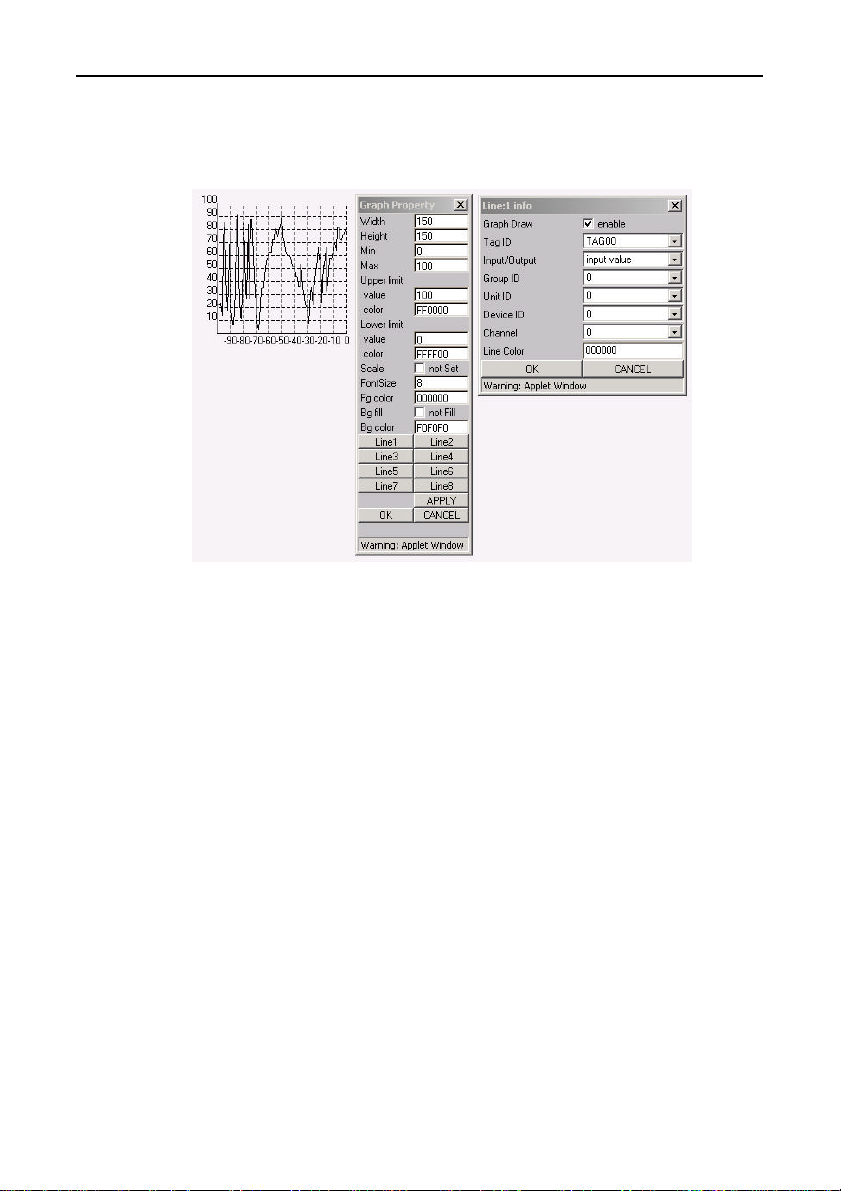
(3) Graph: Graph display
External view of the Properties dialog box
component
Figure 6.21. Graph
Indicates changes in I/O values in a polygon graph format.
An input channel can be specifying by clicking on the [Line] button
and specifying a value in units of "Lines". A maximum of eight
channels can be displayed simultaneously.
The horizontal axis represents up to 100 count values for the
scanning interval.
SVR-MMF(FIT) 53
Page 67
Creation and a Display of a Monitoring Screen
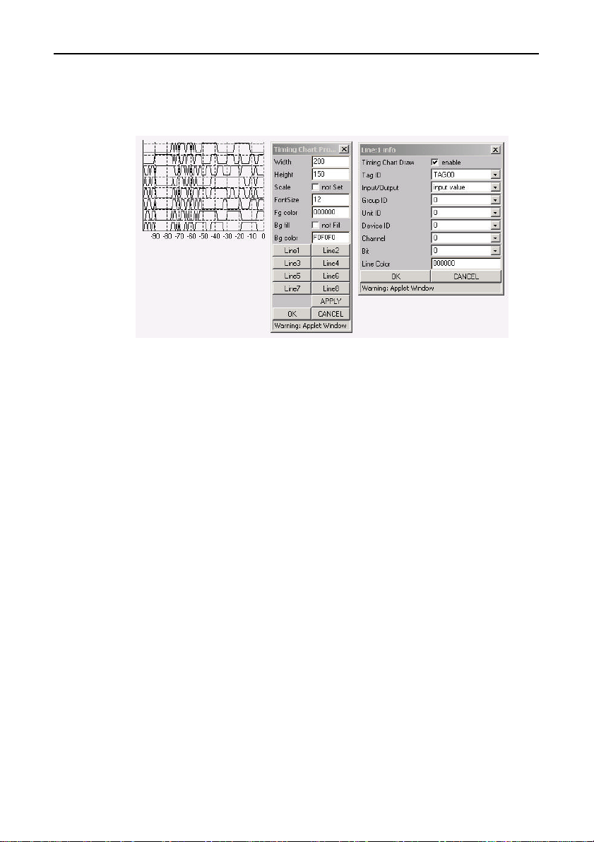
(4) Tchart: Timing chart display
External view of the Properties dialog box
component
Figure 6.22. Tchart
Displays changes in I/O bit on/off patterns in a polygon graph
format.
An input channel can be specifying by clicking on the [Line] button
and specifying a value in units of "Lines". A maximum of eight
channels can be displayed simultaneously.
The horizontal axis represents up to 100 count values for the
scanning interval.
SVR-MMF(FIT)54
Page 68
Creation and a Display of a Monitoring Screen
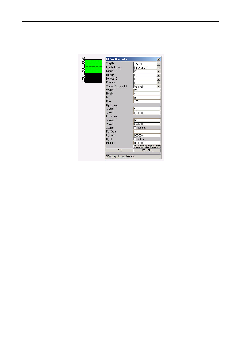
(5) FillBox: Fill box display
External view of the Properties dialog box
component
Figure 6.23. FillBox
- Vertical/Horizontal:
Switches the display orientation between horizontal and vertical
orientations.
The default is [Vertical].
SVR-MMF(FIT) 55
Page 69
Creation and a Display of a Monitoring Screen
(6) Slider: Slide switch
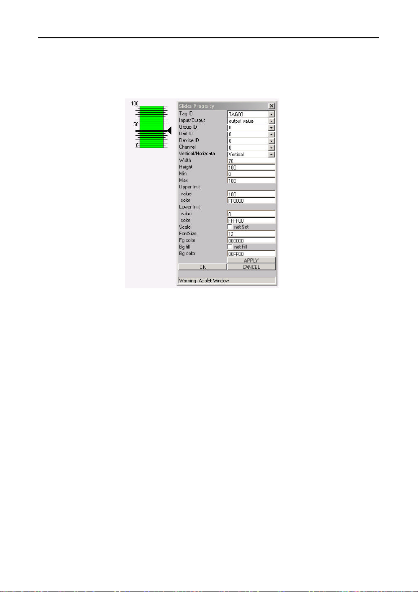
External view of Properties dialog box
the component
Figure 6.24. Slider
- Vertical/Horizontal:
Switches the display orientation between horizontal and vertical
orientations.
The default is [Vertical].
SVR-MMF(FIT)56
Page 70
Creation and a Display of a Monitoring Screen
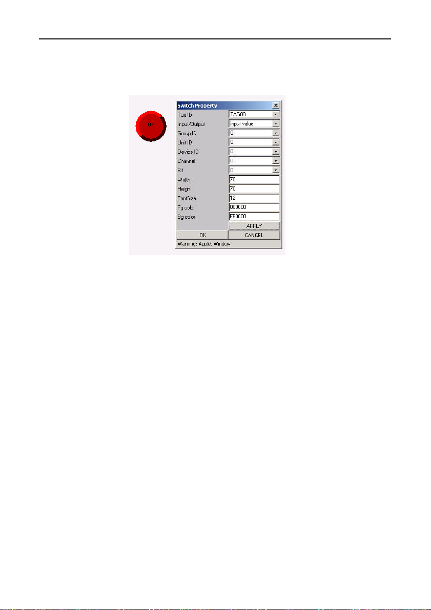
(7) Switch: Switch display
External view of Properties dialog box
the component
Figure 6.25. Switch
This switch displays I/O bits.
In terms of Input/Output, selecting [Input value] displays round
buttons, which indicate input values. Selecting [Output value]
displays square switches, which indicate output values.
SVR-MMF(FIT) 57
Page 71
Creation and a Display of a Monitoring Screen
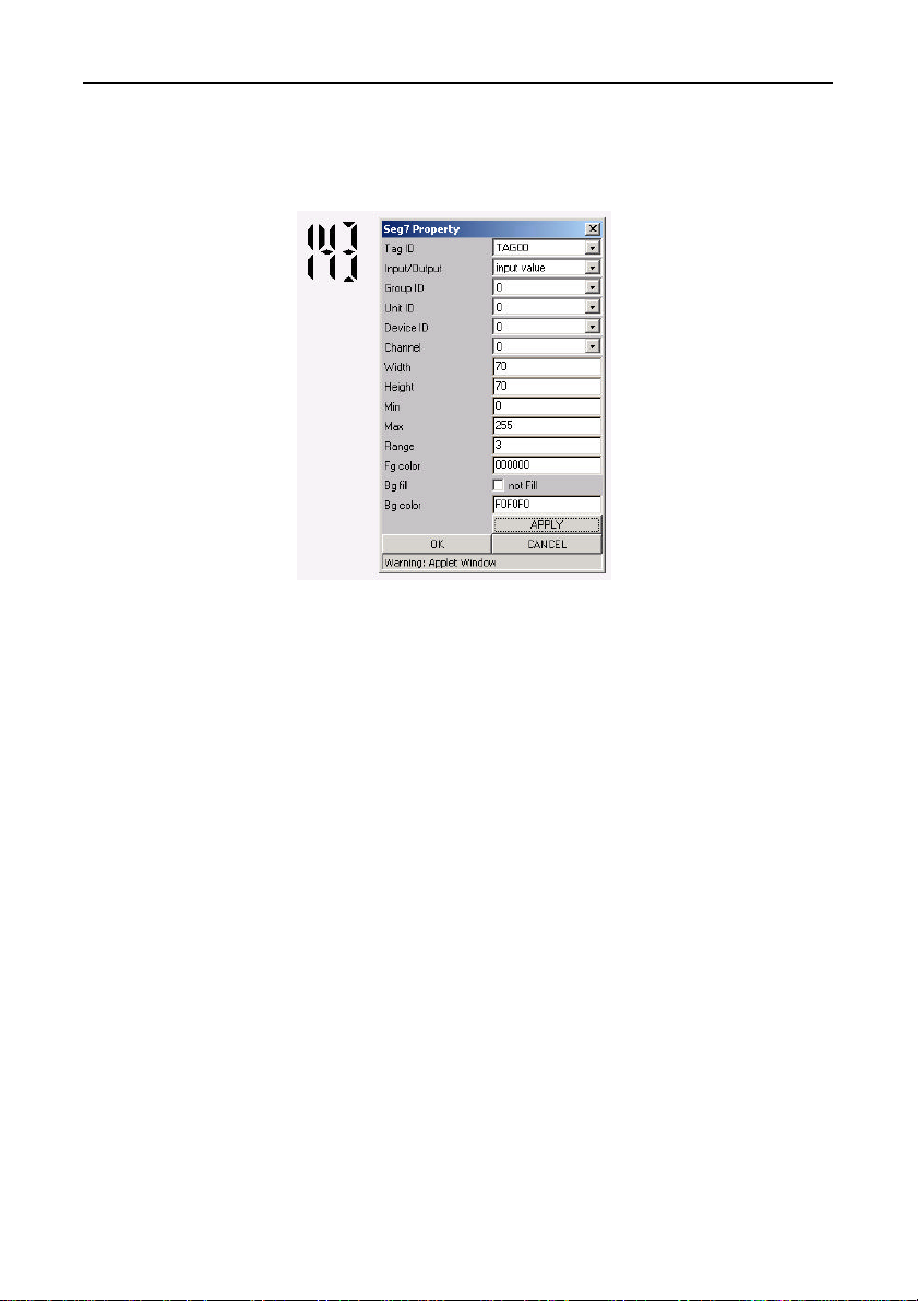
(8) Seg7: Segment-7 display
External view of Properties dialog box
the component
Figure 6.26. Seg7
- Range:
Specify the number of digit positions to be made available for
display purposes.
SVR-MMF(FIT)58
Page 72
Creation and a Display of a Monitoring Screen
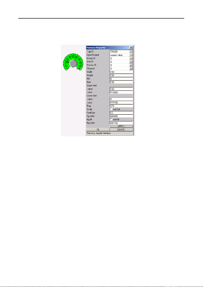
(9) Volume: Volume display
External view of Properties dialog box
the component
Figure 6.27. Volume
- Rag :
Specify a meter display arc angle in a range from 90 to 360.
In terms of Input/Output, selecting [Output value] causes a meter
to be displayed.
SVR-MMF(FIT) 59
Page 73
Creation and a Display of a Monitoring Screen
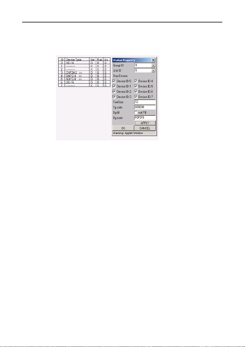
(10) Status: Unit device status display
External view of Properties dialog box
the component
Figure 6.28. Status
- Unit ID:
Specify the Unit ID about which the module installation status is
to be displayed.
- Disp Device:
Assign the desired Device ID from Device IDs 0 to 7.
- When the monitoring screen is running under the [Operation]
mode, clicking on the [Device Type] field brings up a setup dialog
for each device.
SVR-MMF(FIT)60
Page 74
Creation and a Display of a Monitoring Screen
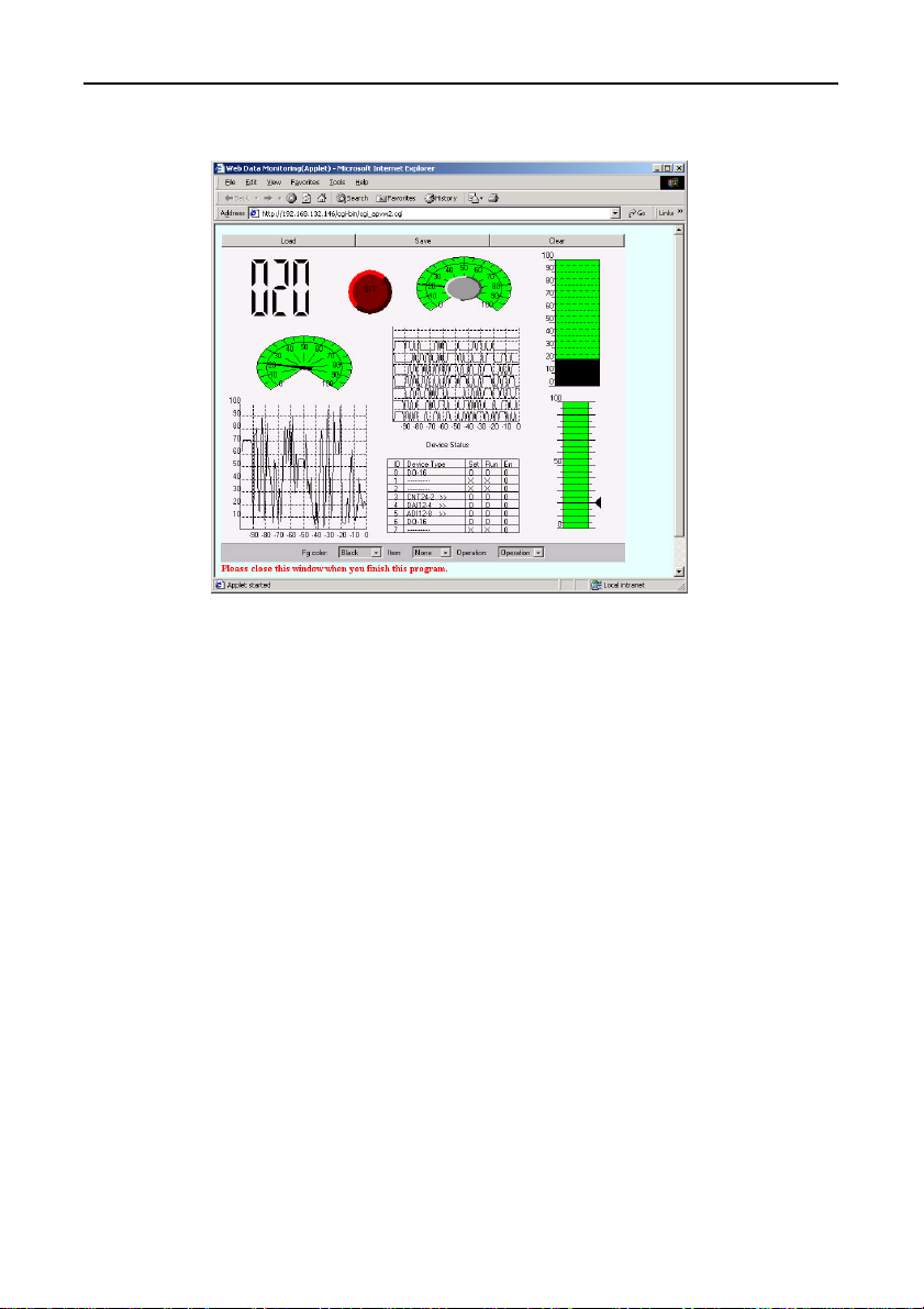
Creation screen image
Figure 6.29. Creation screen
SVR-MMF(FIT) 61
Page 75
Creation and a Display of a Monitoring Screen
Monitoring-Screen Operation
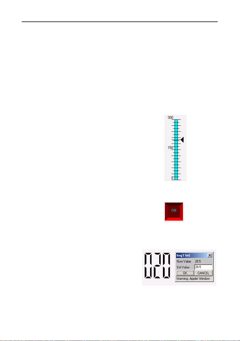
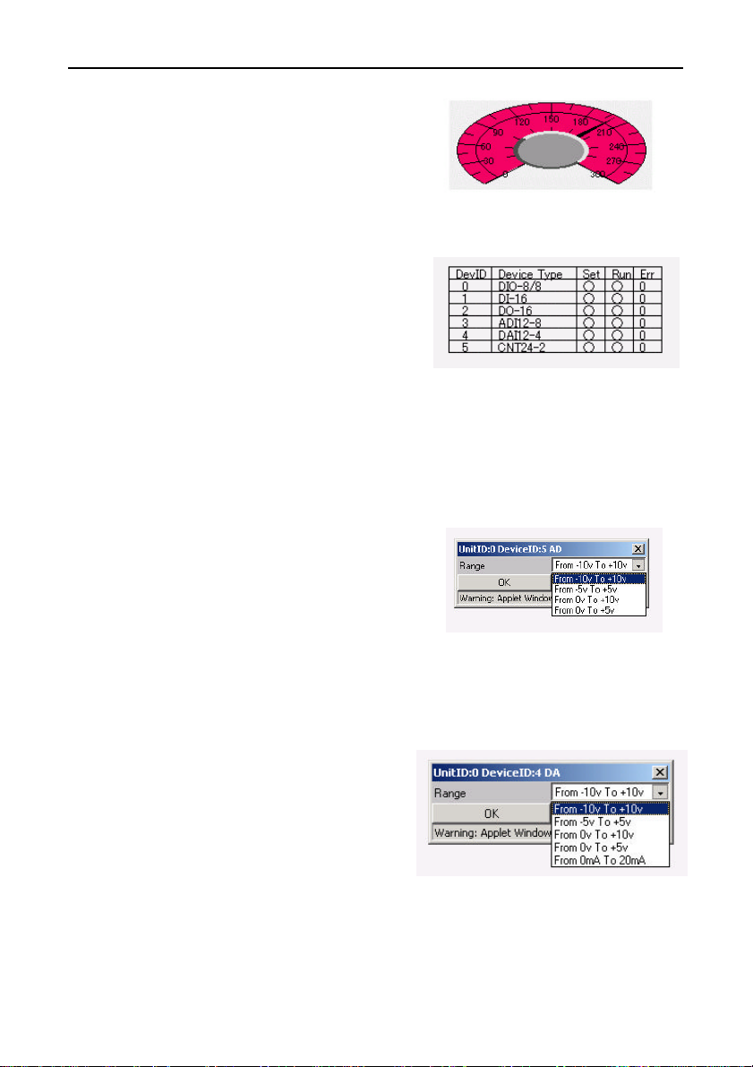
The following graphical buttons can be displayed on monitoring
screens.
- Slider
- Switch
- Seg7
- Volume
- Status
(1) Slider
By left-clicking on the triangle
bar and sliding it, you can
change the output from the
slider.
triangle bar
(2) Switch
Displays the status of the bit
that was set.
Left-clicking on an ON bit
turns it off.
Left-clicking on an OFF bit turns it on.
(3) Seg7
Left-clicking on this
component brings up a dialog
box that enables you to set an
output value from the
keyboard.
SVR-MMF(FIT)62
Figure 6.30. Slider
Figure 6.31. Switch
Figure 6.32. Seg7
Page 76
Creation and a Display of a Monitoring Screen
(4) Volume
By left-clicking on the
memory content of the value to
be output, you can change the
output value.
Figure 6.33. Volume
(5) Status
Left-clicking on [Run] for a
given Device ID brings up a
[Start/Stop] dialog box.
Left-clicking on [Device Type]
for a given Device ID brings
up a basic setup dialog box.
Figure 6.34. Basic Setup Dialog Box
A basic setup dialog box is displayed only for the following
modules: ADI12-8(FIT), AI12-4(FIT), and CNT24-2(FIT).
1. ADI12-8(FIT)
An input signal range must be set.
The following module ranges
can be used: -10 to +10V,
-5 to +5V, 0 to +10V,
and 0 to +5V.
Please refer to the Module
Manual for further details.
2. DAI12-4(FIT)
An input signal range must be set.
The following module
ranges can be used: -10 to
+10V, -5 to +5V, 0 to
+10V, 0 to +5V, and 0 to
20mA.
Please refer to the Module
Manual for further details.
SVR-MMF(FIT) 63
Figure 6.35. ADI12-8(FIT)
Figure 6.36. DAI12-4(FIT)
Page 77
Creation and a Display of a Monitoring Screen
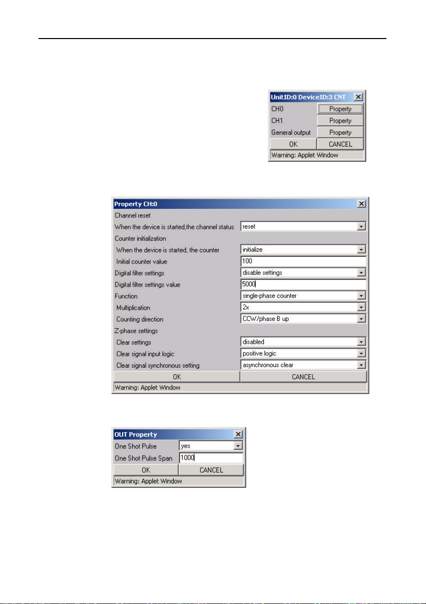
3. CNT24-2(FIT)
This brings up the type of dialog shown on the right.
CH0 and CH1 are used to set the desired channel for counting
input signals.
The generic output provides
output-related settings.
Please refer to the Module
Manual for further details.
Figure 6.37. CNT24-2(FIT)
Figure 6.38. Property CH0
Figure 6.39. OUT Property
SVR-MMF(FIT)64
Page 78
Creation and a Display of a Processing Task
7. Creation and a Display of a Processing
Task
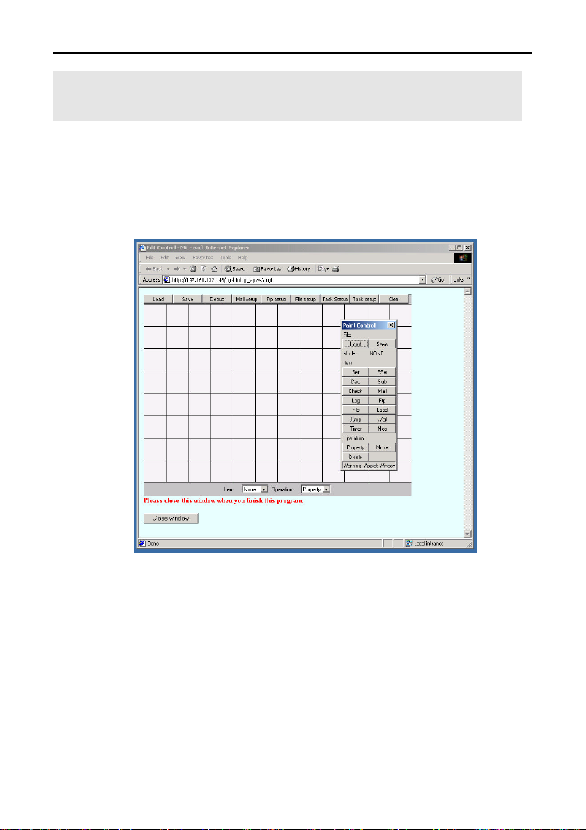
You can use a browser to access the Monitoring & Control Server
from a host computer to view and edit executable tasks.
Operation Procedure
Clicking edit/view task displays the following screen.
Figure 7.1. Menu
Menu bar functions:
Load: Loads and displays saved task processing.
Save: Saves the edited task processing.
Debug: Displays the debug dialog.
Mail setup: Specifies the host settings and other setup information
for using mail.
Ftp setup: Specifies the host settings and other setup information
for using FTP to transfer data.
SVR-MMF(FIT) 65
Page 79
Creation and a Display of a Processing Task
File setup: Specifies settings for saving collected data to a file.
Task Setup: Specifies the operating mode for a running task.
Task Status: Displays the status of a running task.
Clear: Clears the displayed task processing screen.
Item: Selects a component.
Operation: Selects an operation.
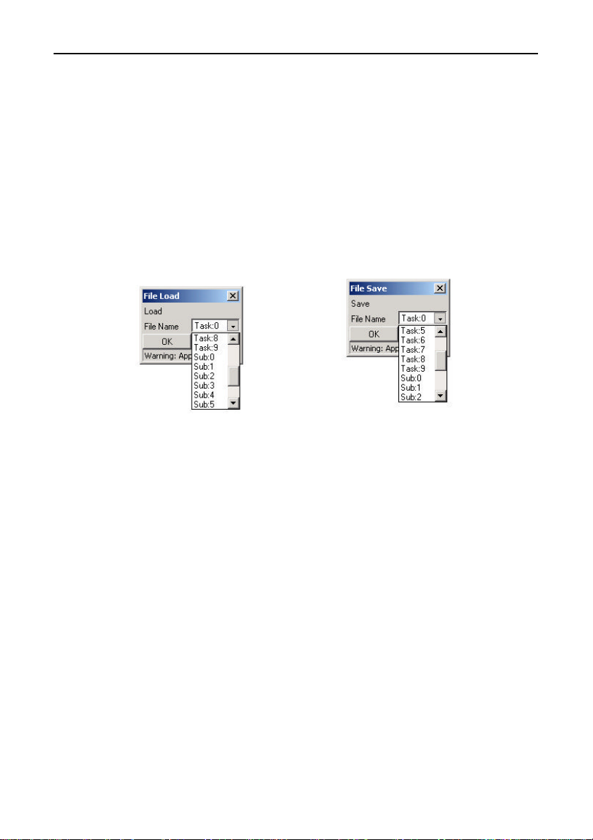
- Load: - Save:
Loads and displays saved Saves the edited task
task processing. processing.
Figure 7.2. File Load Figure 7.3. File Save
A maximum of 10 tasks can be created and executed simultaneously.
A maximum of 10 subroutines can be created and called from the
tasks.
SVR-MMF(FIT)66
Page 80
Creation and a Display of a Processing Task
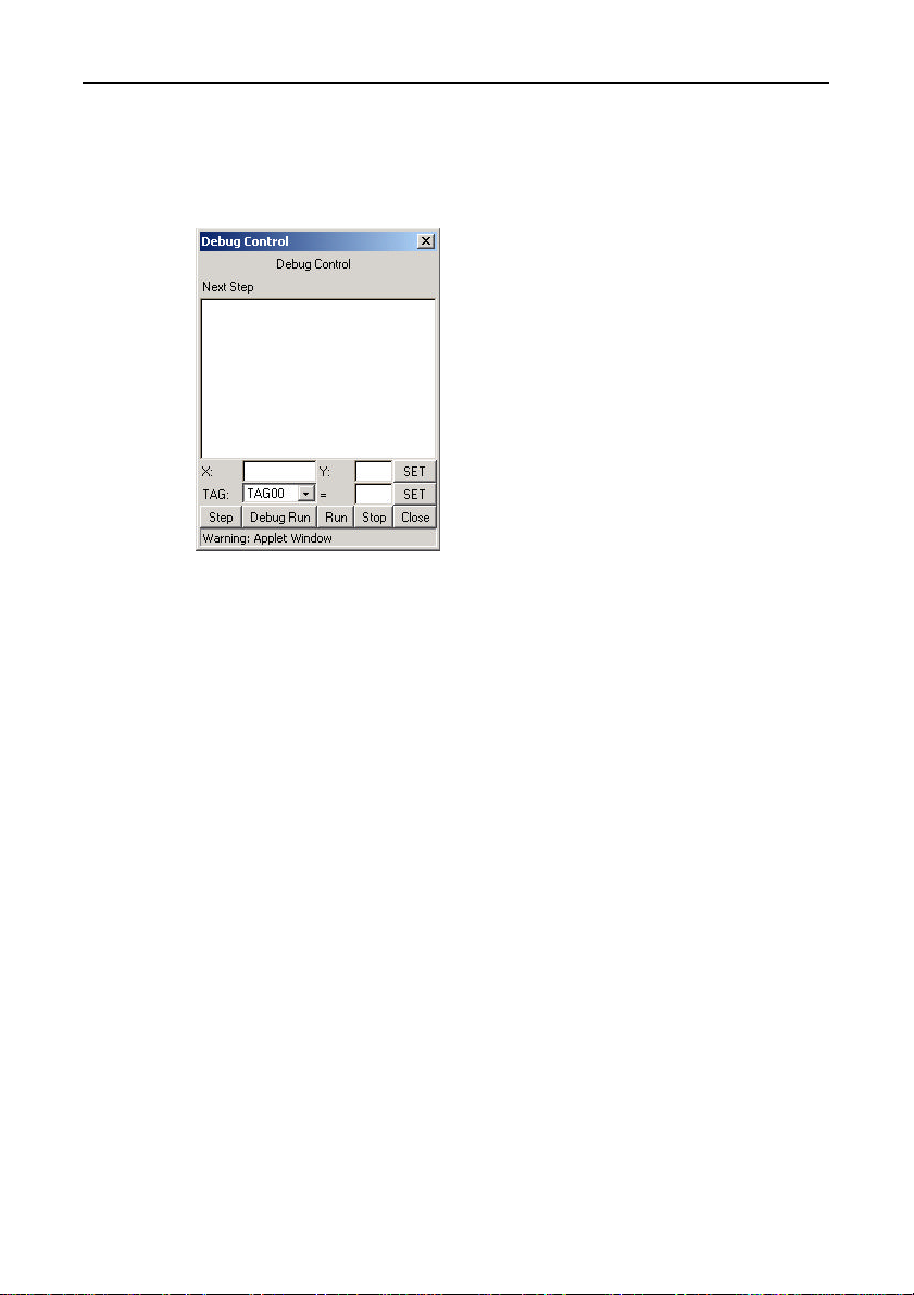
- Debug: Displays the debug dialog.
Use [Debug Run] to display the current task status.
As execution is synchronized with the browser, it is slower than the
actual processing speed.
- Enter values in the X and Y fields,
then click [SET] to change the
execution position.
- You can modify the value for a TAG
number by selecting the TAG,
entering the new value, then clicking
[SET].
Figure 7.4. Debug Control
Step: Execute component instructions one at a time.
Debug Run: Run step execution continuously.
Run: Execute task in normal mode.
Stop: Stop task.
Close: Close dialog.
SVR-MMF(FIT) 67
Page 81
Creation and a Display of a Processing Task
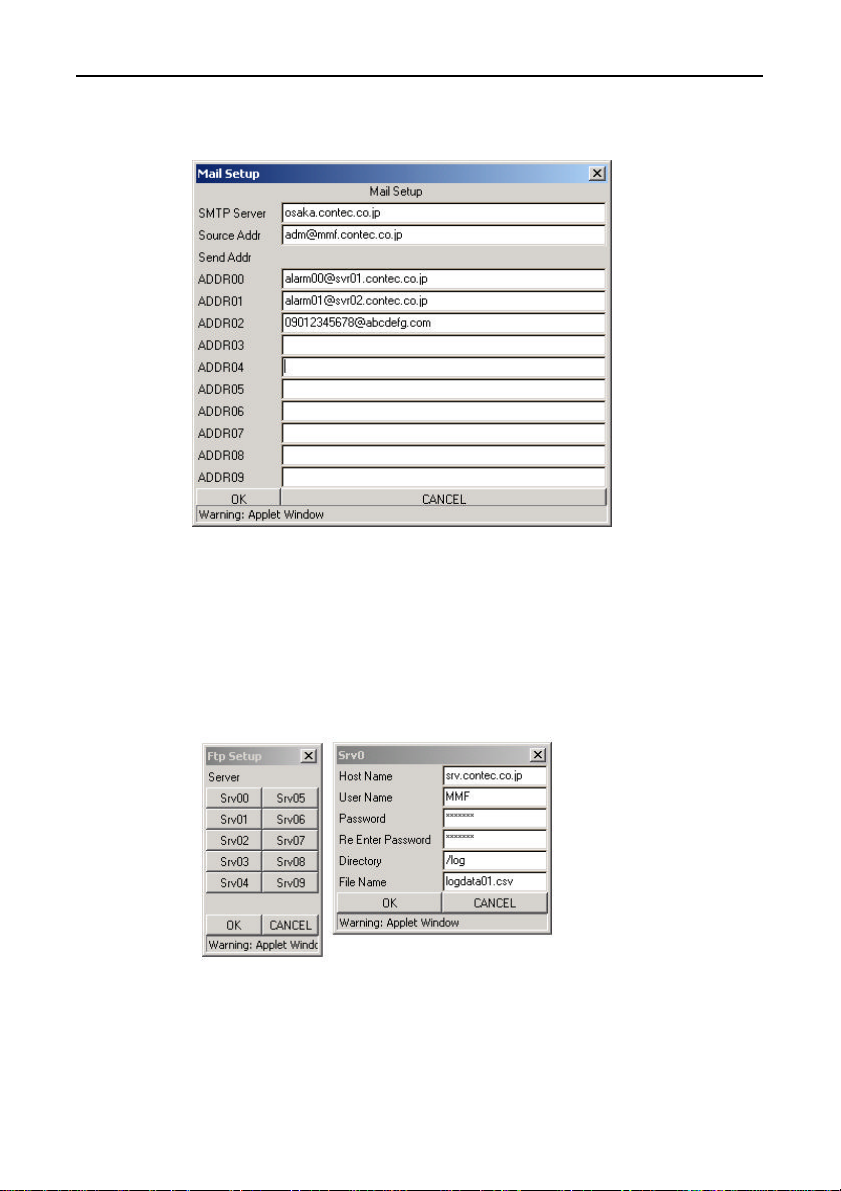
- Mail Setup: Specifies the host settings and other setup
information for using mail.
Figure 7.5. Mail Setup
Set these parameters when using e-mail to send alarms or collected
data.
A maximum of 10 destination addresses can be set.
- Ftp Setup: Specifies the host settings and other setup
information for using FTP to transfer data.
Figure 7.6. Ftp Setup
Set these parameters when using FTP to send collected data.
A maximum of 10 destination hosts can be specified.
SVR-MMF(FIT)68
Page 82
Creation and a Display of a Processing Task
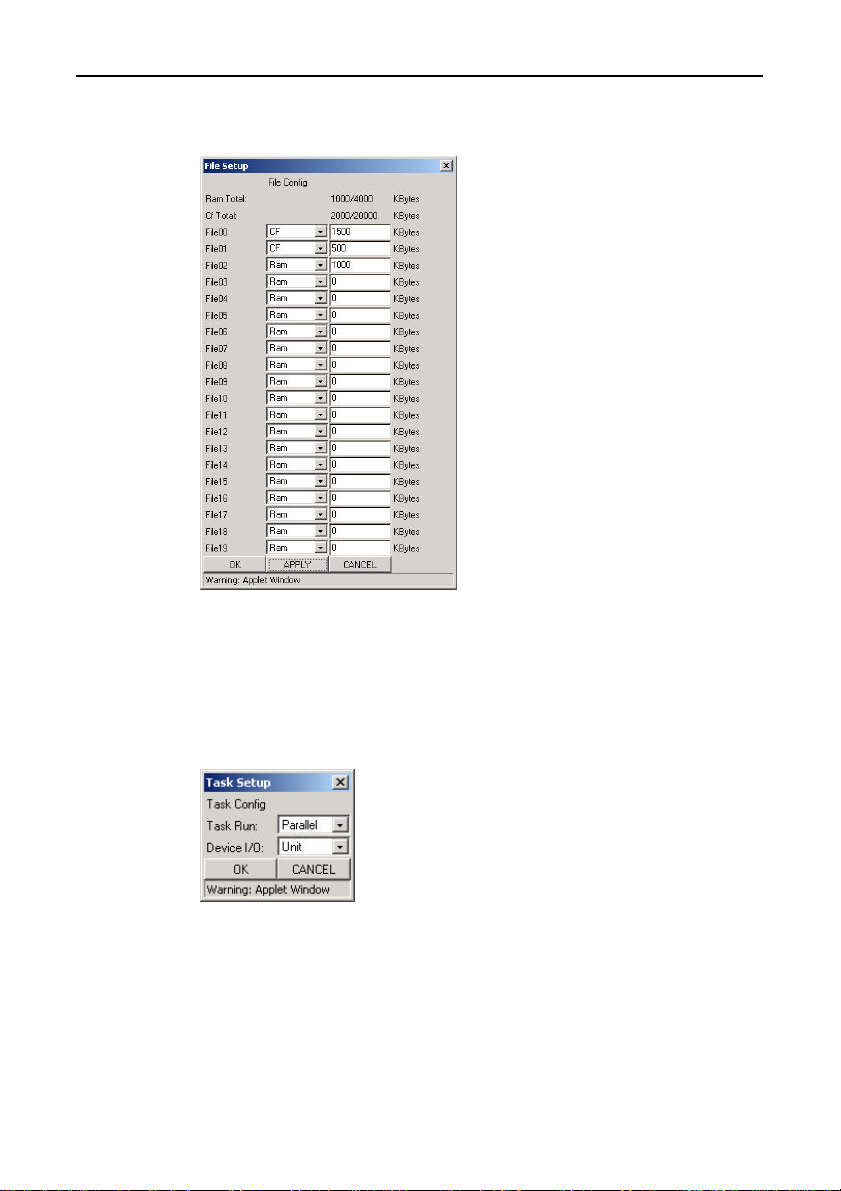
- File Setup: Specifies settings for saving collected data to a file.
Files for storing collected data
can be created in the RAM area
or Cf area.
Files created in the RAM area are
lost when the power to the device
is turned off.
Files created in the Cf area are
not erased when the power is
turned off but data may be lost if
the power is turned off during a
write operation.
Specify the size of the file.
When the saved data exceeds the
file size, old data is deleted and
new data saved at the end of the
file.
Figure 7.7. File Setup
- Task Setup: Specifies the operating mode for a running task.
- Task Run: Set the execution mode for the created tasks.
The available modes are “Parallel” and “Serial”.
When “Serial” is specified, task 1 executes after task
0 completes (when an instruction passes control
outside the task screen). Tasks are executed in
order starting from the lowest task number.
Task 0 executes again after task 9 completes.
When “Parallel” is specified, the instructions
from one cell are executed from task 0 then the
instructions from one cell are executed from
task 1.
Figure 7.8. Task Setup
Tasks are executed in order starting from the lowest task number.
After task 9 executes, the instructions in the second cell for task 0
are executed. If operations such as control, data collection, and
sending mail are implemented in separate tasks, this prevents the
processing time required for mail sending from affecting control
operations.
SVR-MMF(FIT) 69
Page 83
Creation and a Display of a Processing Task
- Device I/O: This specifies whether I/O device access is
performed by [Unit] or by [Channel]. Channel
access must be specified if a multiple supervisory
controllers are accessing a remote device. Otherwise,
please specify [Unit] access for normal operation.
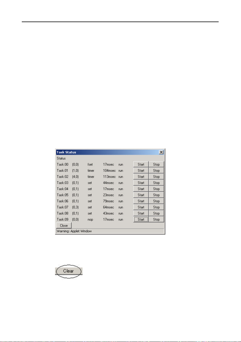
- Task Status: Displays the status of a running task.
Displays the X, Y coordinates currently being
executed by each task in the format (9, 9).
Displays the instruction currently being executed by
each task ([check], [set], [sub], [timer], etc.)
Displays the time interval for each task to execute
the instructions at coordinates (0, 0) in msec.
(Displays the scan time.)
Displays the execution status of each task.
You can click the [Start] and [Stop] buttons to start
and stop task execution.
Figure 7.9. Task Stat us
- Clear: Clears the displayed task processing screen.
Figure 7.10. Clear
SVR-MMF(FIT)70
Page 84
Creation and a Display of a Processing Task
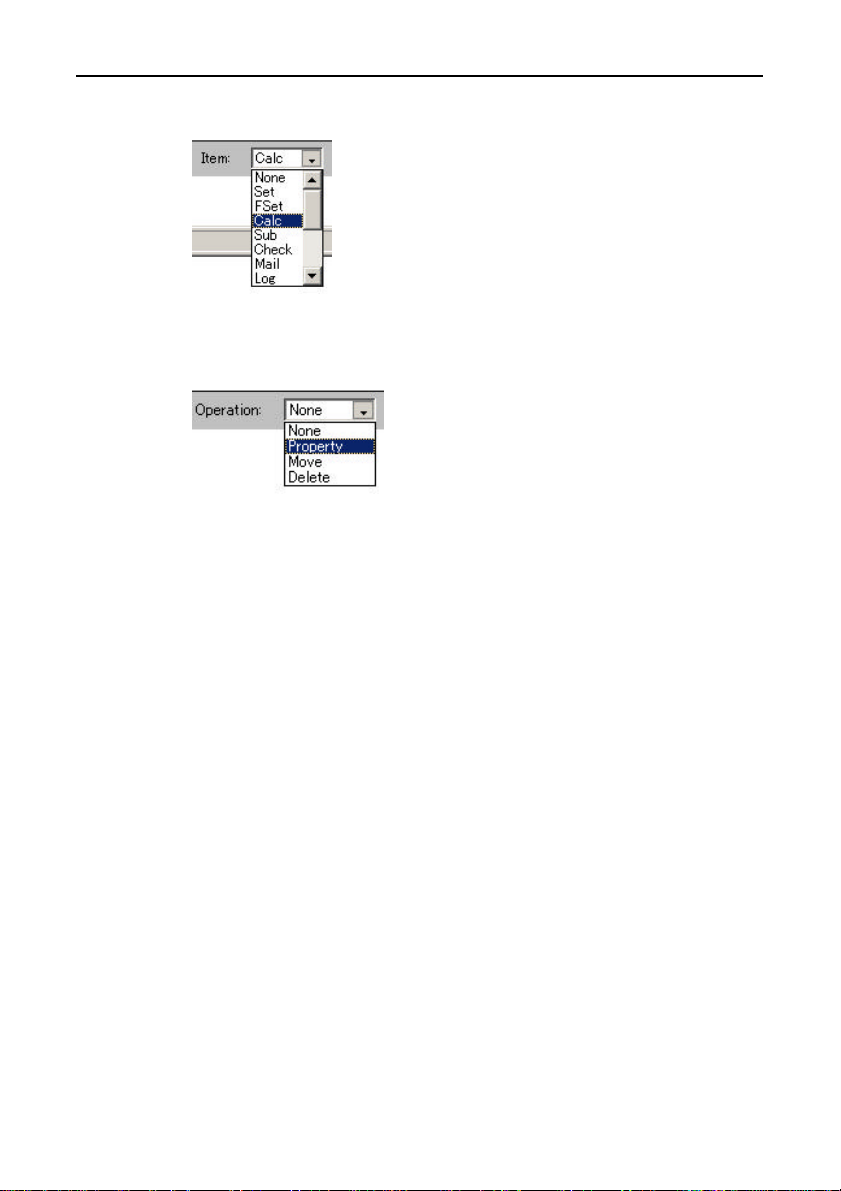
- Item: Selects a component.
Figure 7.11. Item
- Operation: Selects an operation.
Figure 7.12. Operation
SVR-MMF(FIT) 71
Page 85
Creation and a Display of a Processing Task
Basic Operations
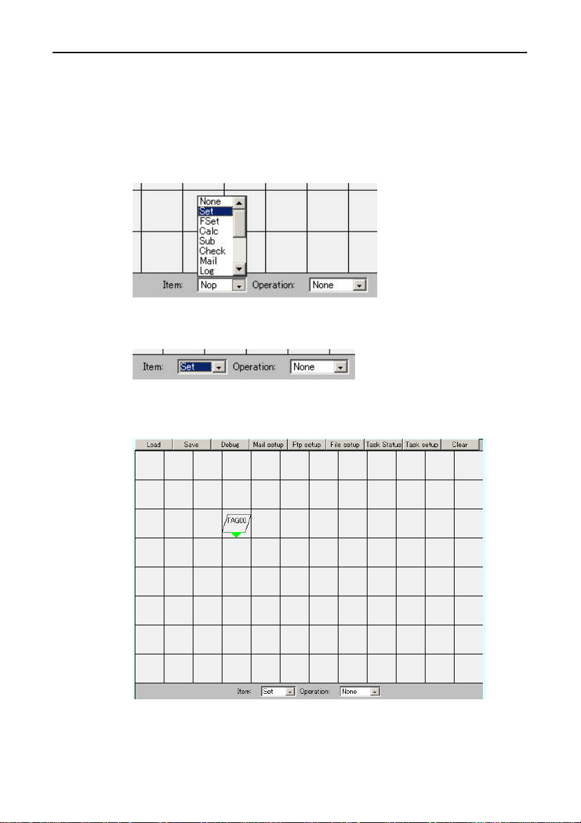
(1) Parts are arranged.
In [Item], select the desired component, and click on it on the
screen in order to lay it out.
Example: Inserting a Set instruction
Figure 7.13. Item
Figure 7.14. Item Set
Single-clicking on the screen displays the meter.
↓
Figure 7.15. Set
SVR-MMF(FIT)72
Page 86
Creation and a Display of a Processing Task
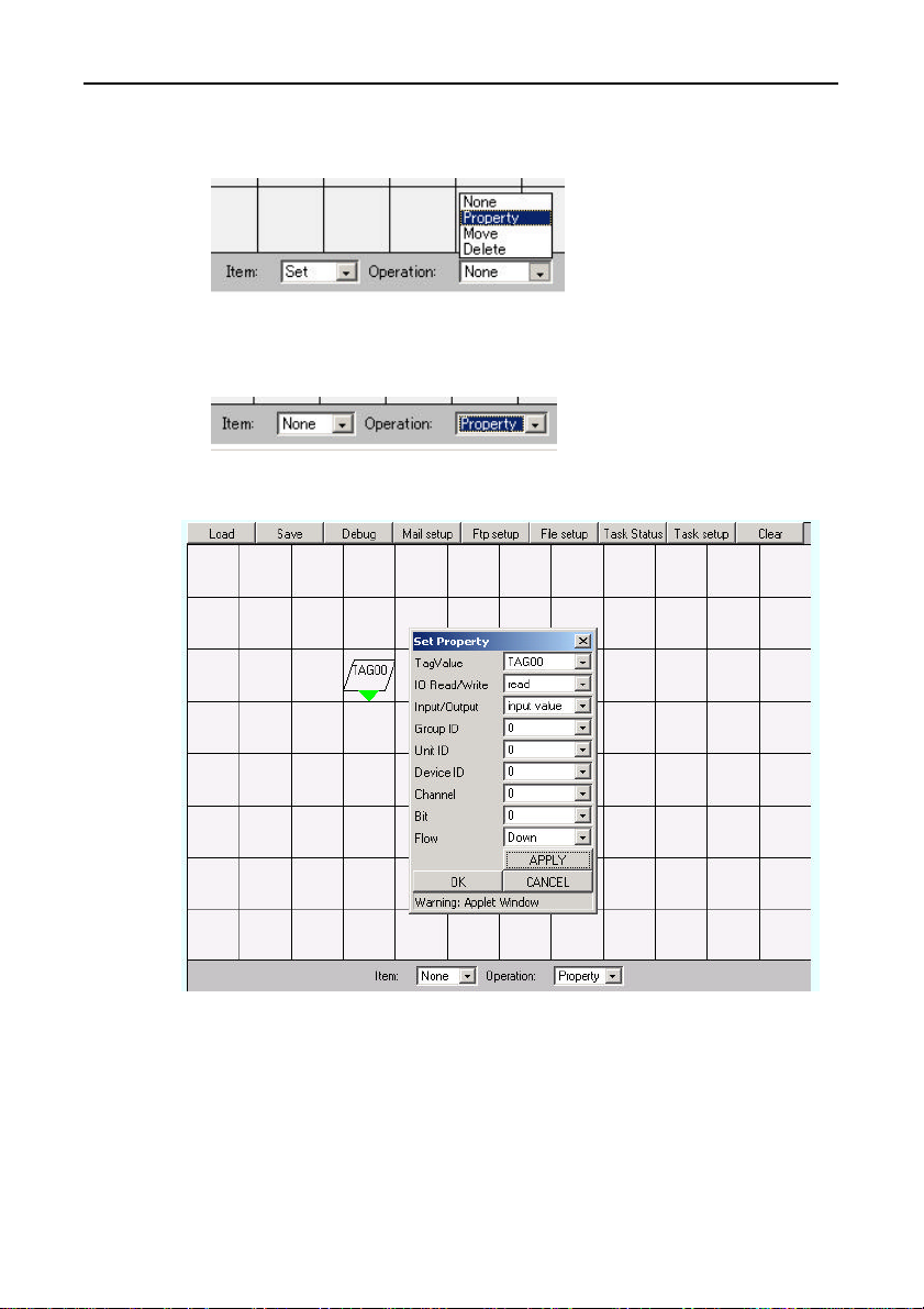
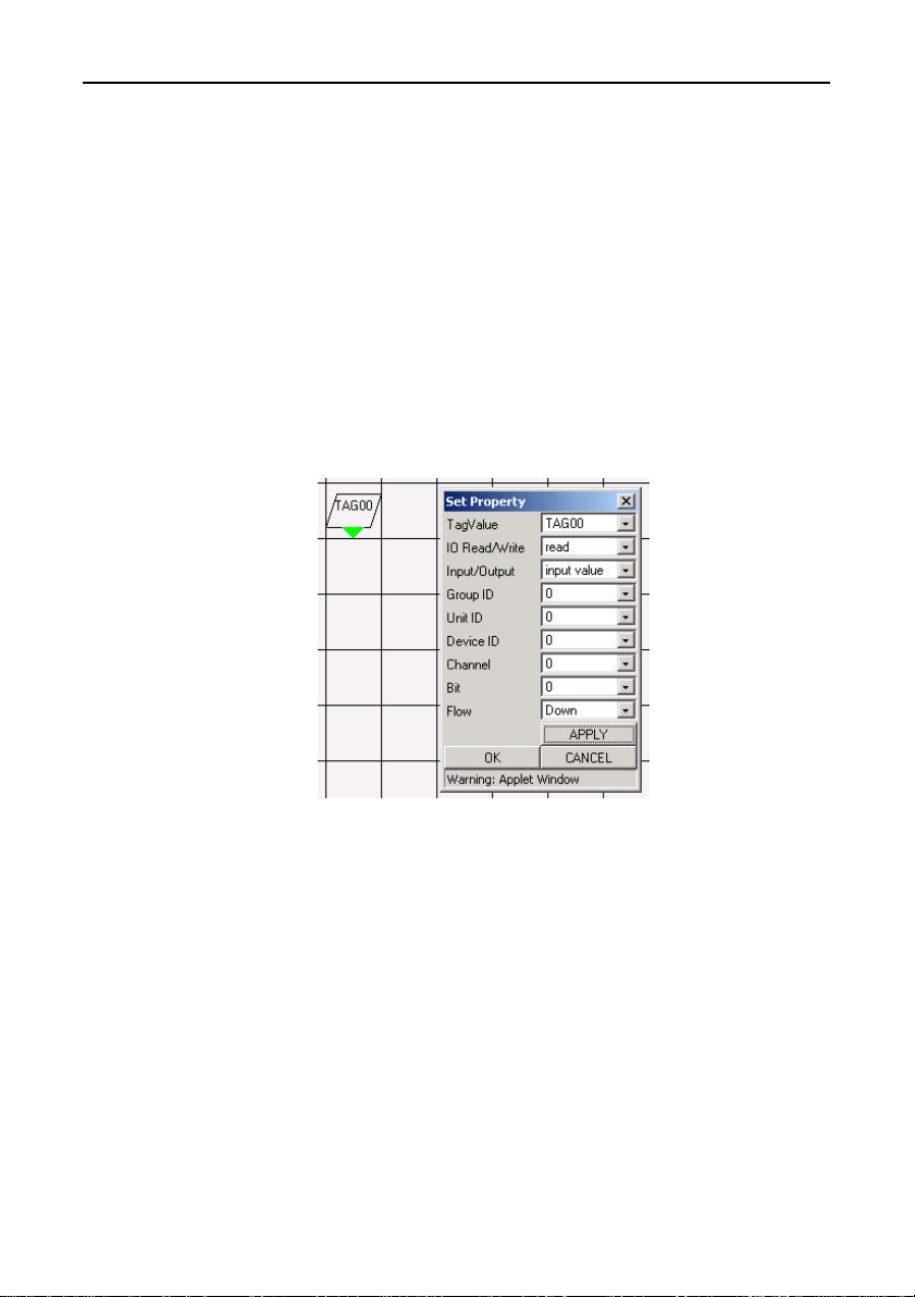
(2) In [Operation], select [Properties], and click on the component
to open the [Properties] box.
Figure 7.16. Operation
↓
Figure 7.17. Operation Property
Figure 7.18. Property
Components have parameters that control their function and “flow”
that controls which component is to be executed next.
In this example, device data is read into TAG00 then control is
passed to the next component in the downwards direction (Down).
SVR-MMF(FIT) 73
Page 87
Creation and a Display of a Processing Task
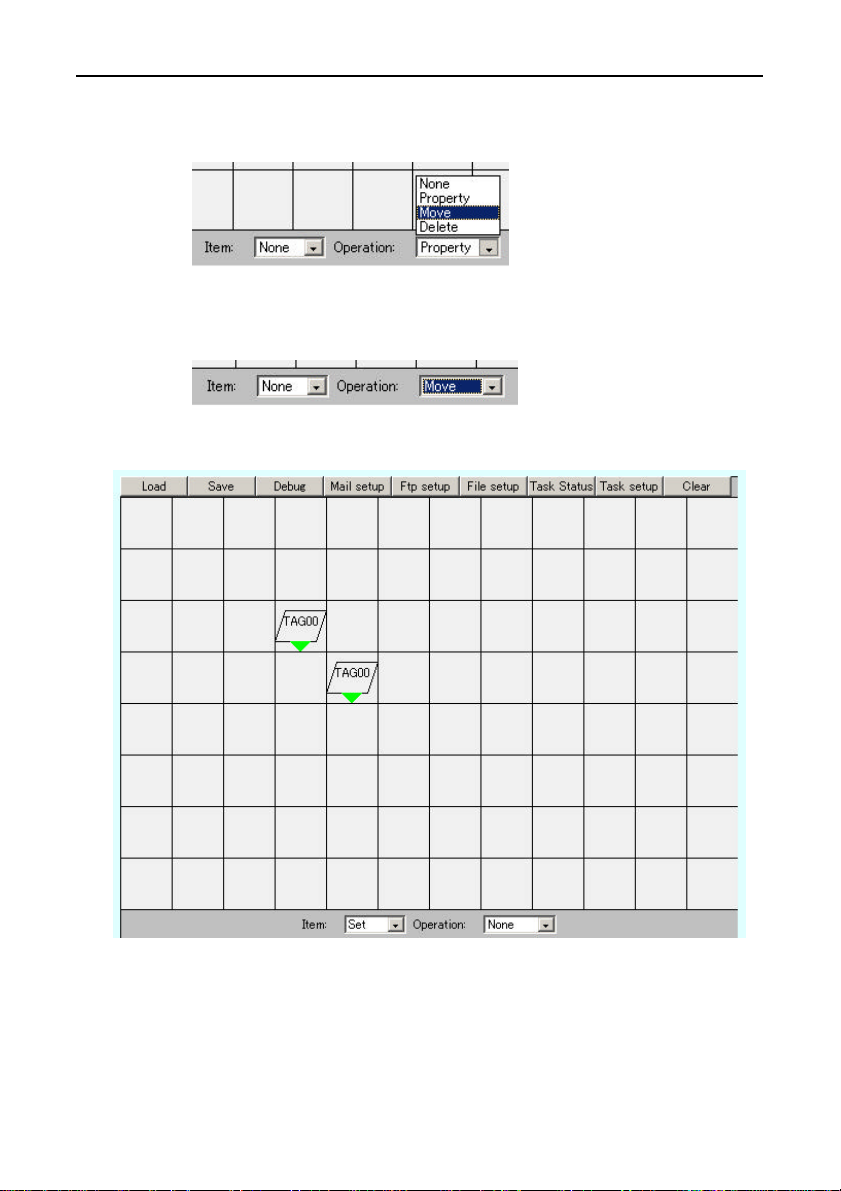
(3) You can also move a component by selecting [Move] in
[Operation].
Figure 7.19. Operation
↓
Figure 7.20. Operation Move
Figure 7.21. Move
By left-clicking the mouse on the component and dragging the mouse, you can
move the components. Releasing the mouse fixes the component at the current
mouse position.
SVR-MMF(FIT)74
Page 88
Creation and a Display of a Processing Task
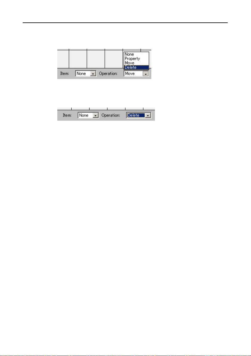
(4) You can delete a component by selecting [Delete] in
[Operation].
Figure 7.22. Operation
↓
Figure 7.23. Operation Delete
Left-clicking on the component deletes it.
(5) Use the procedures described above to lay out the components
and define the task.
You can use the [Save] menu command to save the edited task
processing. This opens a dialog for you to specify the task number
in which to save the task.
You can use the [Load] menu command to load a previously saved
task. This opens a dialog for you to select the task number.
To start executing the new task processing, use the [Task Status]
menu command to [Stop] and then [Start] the task.
SVR-MMF(FIT) 75
Page 89
Creation and a Display of a Processing Task
The Kind and Outline of Parts Which Can Be
Used
Components that can be selected from [Item] on the Menu bar are
described below.
Each component represents a processing function.
When processing completes, execution proceeds to the next cell.
The next cell is determined by the “Flow” setting for the component.
(1) Set: Input or output the device value to or from the specified
TAG number variable.
External view of the Properties dialog box
component
Figure 7.24. Set
If [IO Read/Write] is set to [read], the component sets the device
value in the TAG number variable. If [write] is selected, the value of
the TAG number variable is output to the device.
The device is specified by the Group ID, Unit ID, Device ID, and
Channel.
A [Group ID] value of 9 indicates one of the local devices stacked
with this device.
The [Bit] parameter can be set to 0 to 7 or to [all]. If [Bit] is set to
between 0 and 7, the specified bit only is input or output.
Bit: 0 is the LSB (the result of ANDing the variable with 0x01).
Select [all] to input or output the entire channel value.
SVR-MMF(FIT)76
Page 90
Creation and a Display of a Processing Task
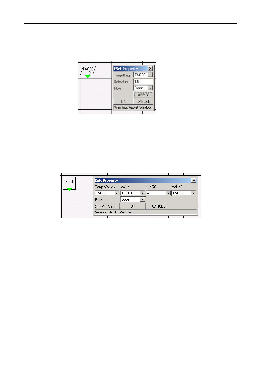
(2) FSet: Set a fixed value to a specified TAG number variable.
External view Properties dialog box
of the component
Figure 7.25. FSet
- SetValue: Enter the value to set.
(3) Calc: calculation
External view Properties dialog box
of the component
Figure 7.26. Calc
Performs a calculation on the TAG number variable selected in
[Value1] and the TAG number variable selected in [Value2], and sets
the result in the TAG number variable selected in [TargetValue]
Available calculations are addition, subtraction, multiplication,
division, remainder, AND, and OR.
SVR-MMF(FIT) 77
Page 91
Creation and a Display of a Processing Task
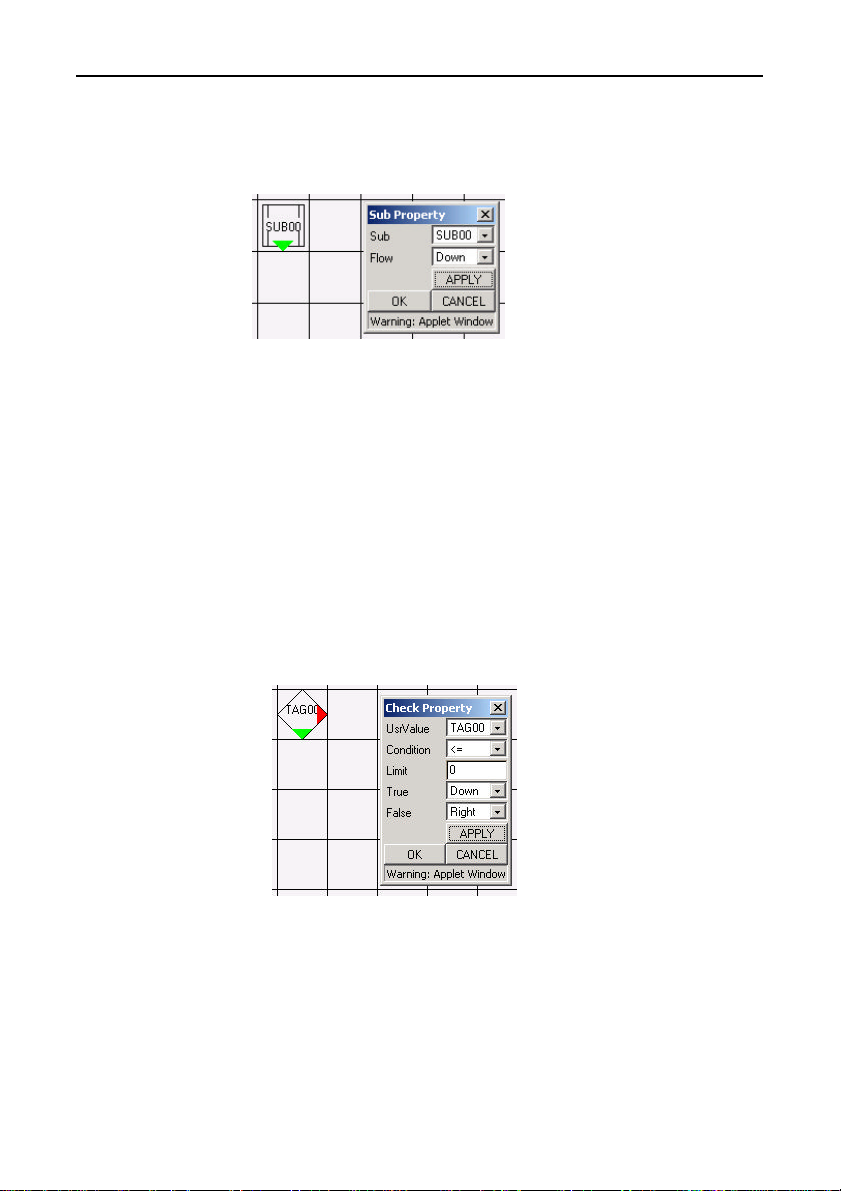
(4) Sub: Call a subroutine
External view Properties dialog box
of the component
Figure 7.27. Sub
Calls the selected subroutine. Executes the next cell after subroutine
execution completes.
Subroutines may be called from within subroutines up to a
maximum nesting of 10 levels.
If an attempt is made to call a subroutine beyond that nesting level,
the subroutine is not executed and returns immediately.
(5) Check: Conditional branch
External view Properties dialog box
of the component
Figure 7.28. Check
Processing branches based on the result of comparing the value set
in [Limit] with the selected TAG number variable.
The available [Condition] settings are <=, >, =, <=, and <.
SVR-MMF(FIT)78
Page 92
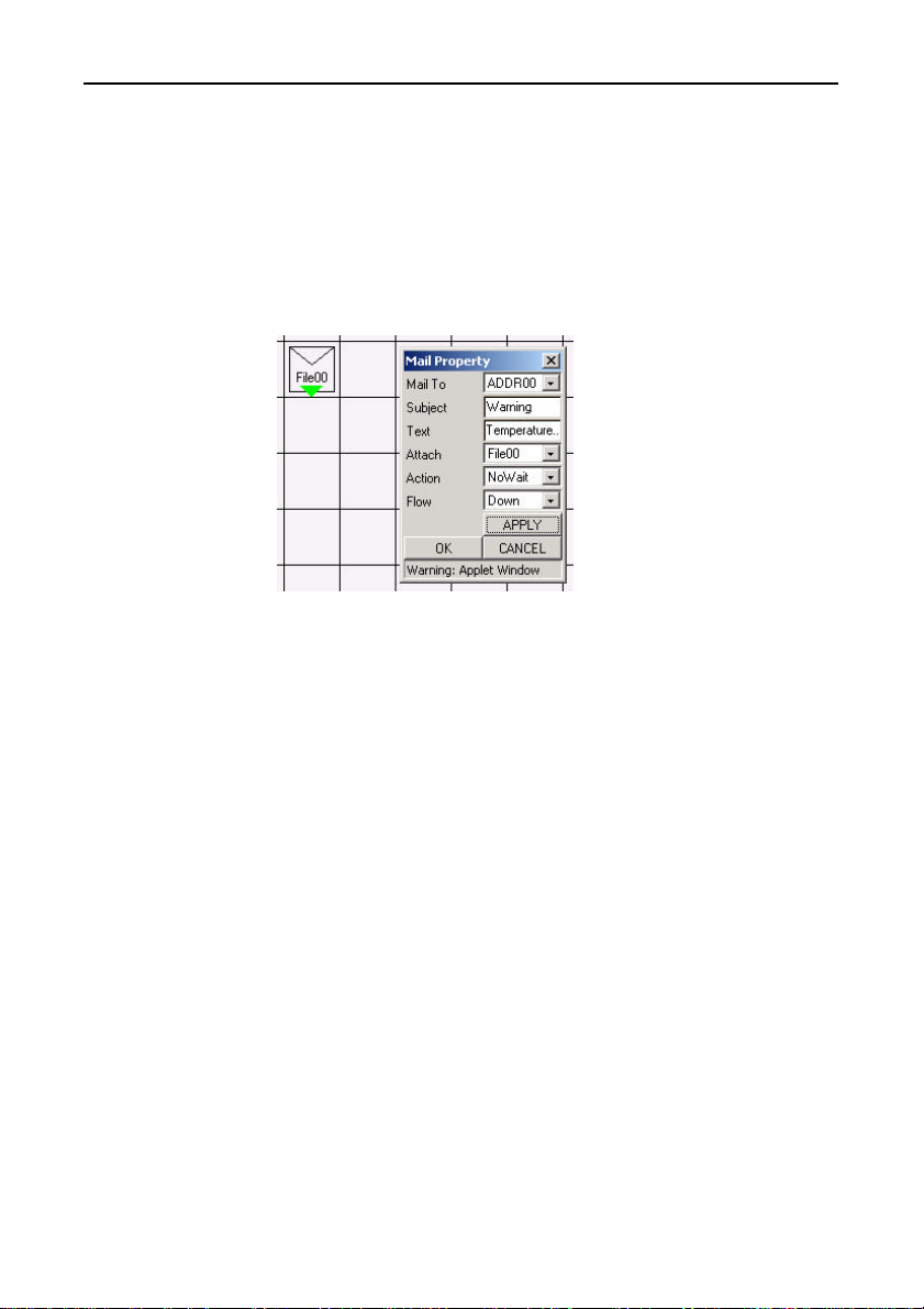
Creation and a Display of a Processing Task
Execution branches depending on the specified condition.
When the condition is satisfied: True
When the condition is not satisfied: False
(6) Mail: Send an alarm by e-mail.
External view Properties dialog box
of the component
Figure 7.29. Mail
- Mail To: Select the destination address for the e-mail.
- Subject: Select the subject for the e-mail.
- Text: Select the text for the e-mail.
- Attach: Select the log file to attach to the e-mail.
If [NONE] is selected, no file is attached.
- Action: If [Wait] is specified, execution does not proceed to
the next step until sending the mail to the SMTP
server completes. If [NoWait] is specified, the send
request is handled by a separate task and execution
proceeds to the next cell.
SVR-MMF(FIT) 79
Page 93
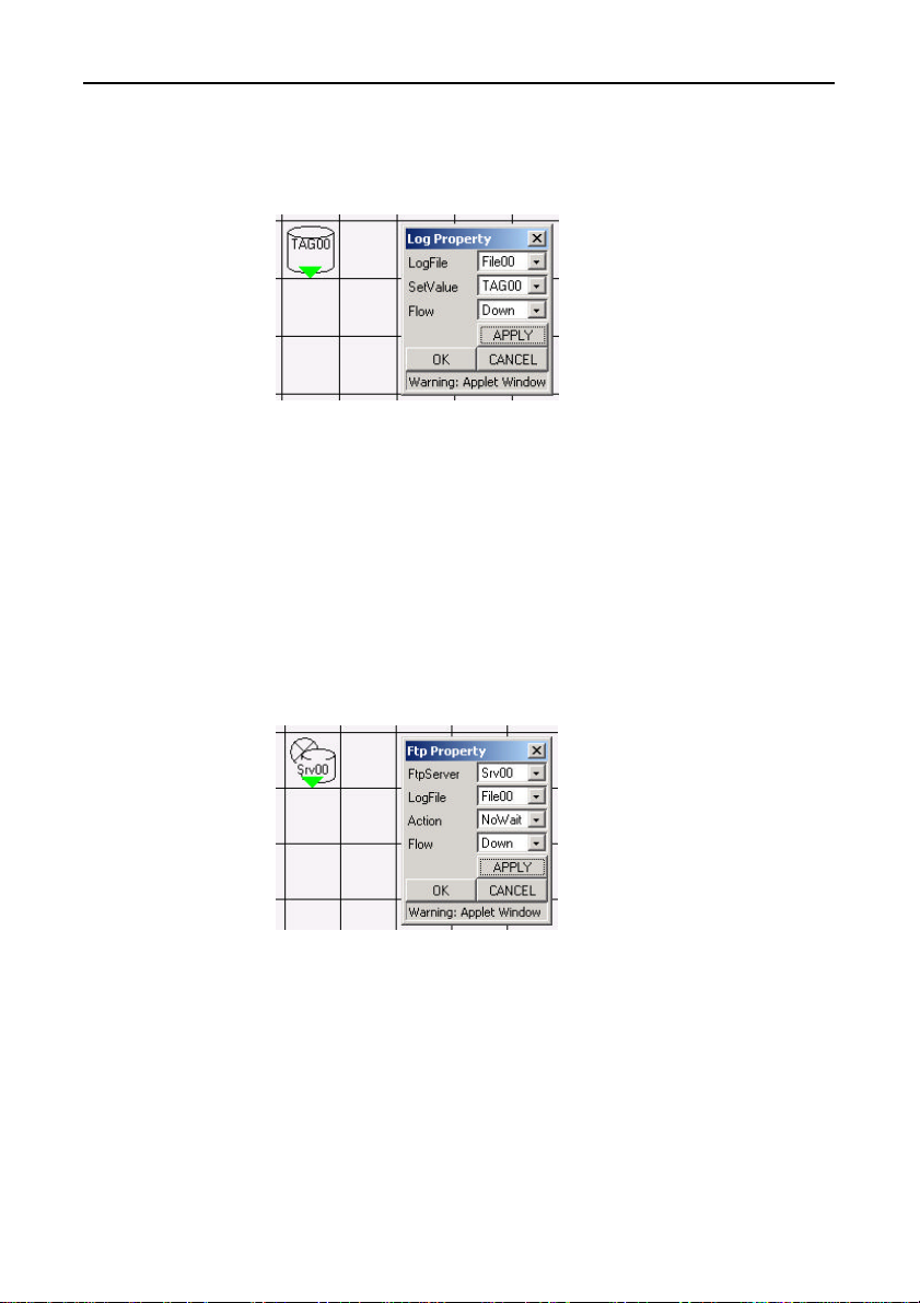
Creation and a Display of a Processing Task
(7) Log: Save collected data to a file.
External view Properties dialog box
of the component
Figure 7.30. Log
- LogFile: Select the file in which to write the data.
- SetValue: Select the data to write.
The available range is TAG00 to TAG99. The data is
saved in comma-separated value (CSV) format.
Date, time, and carriage return can be select as data to
write to the file.
(8) Ftp: Sen d collected data via FTP.
External view Properties dialog box
of the component
Figure 7.31. Ftp
- FtpServer: Select the destination host.
- LogFile: Select the file to send.
- Action: If [Wait] is specified, execution does not proceed to
the next step until sending the mail to the SMTP
server completes. If [NoWait] is specified, the send
request is handled by a separate task and execution
proceeds to the next cell.
SVR-MMF(FIT)80
Page 94
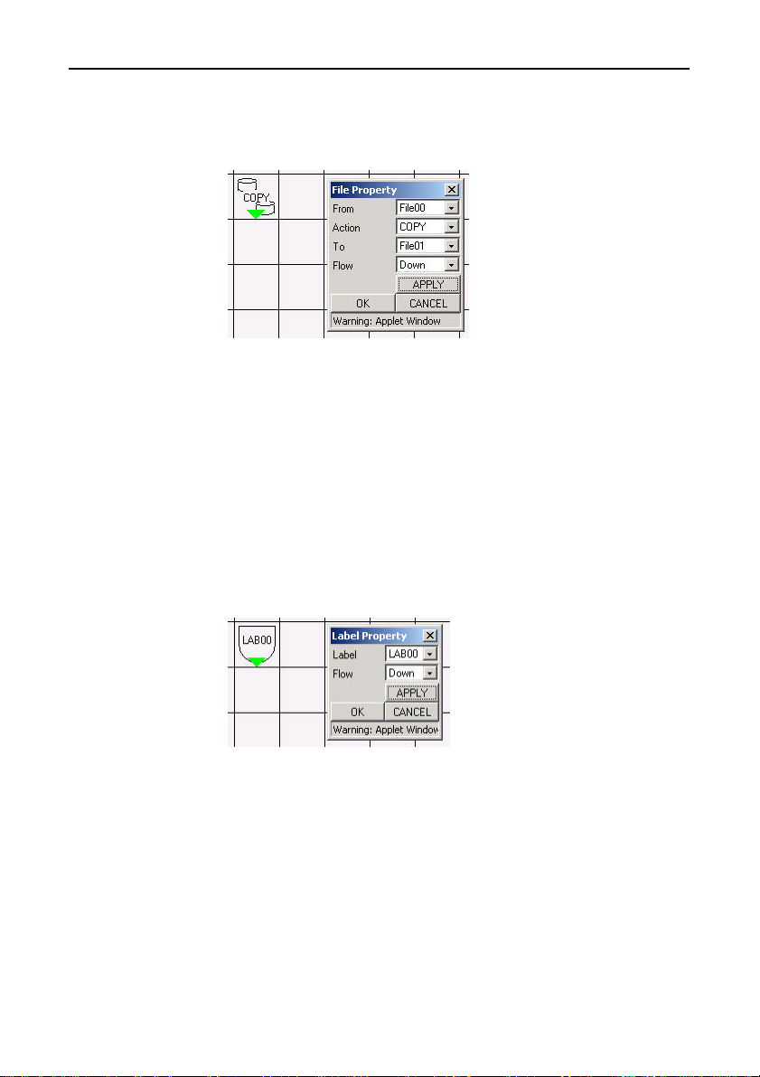
Creation and a Display of a Processing Task
(9) File: Perform an operation on a log file.
External view Properties dialog box
of the component
Figure 7.32. File
- From: Select the file on which to perform the operation.
- Action: Select the file operation. The available operations are
[COPY], [MOVE], [APPEND], and [DEL].
- To: Select the target file
(10) Label: Create a label.
External view Properties dialog box
of the component
The [To] file is ignored if the selected [Action] is
[DEL].
Figure 7.33. Label
- Label: Select the label name. The label is used to indicate the
destination for a subsequent Jump instruction.
SVR-MMF(FIT) 81
Page 95
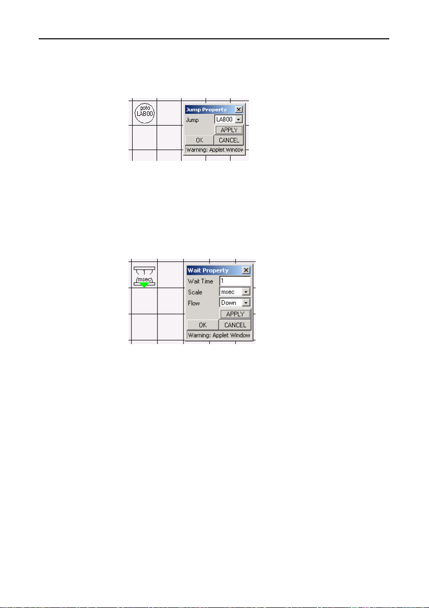
Creation and a Display of a Processing Task
(11) Jump: Jump instruction
External view Properties dialog box
of the component
Figure 7.34. Jump
- Jump: Select the label name.
(12) Wait: Delay processing for a specified time.
External view Properties dialog box
of the component
Figure 7.35. Wait
- Wait Time: Enter the waiting time.
- Scale: Select the units. Available settings are [msec], [sec],
[min], and [hour].
SVR-MMF(FIT)82
Page 96
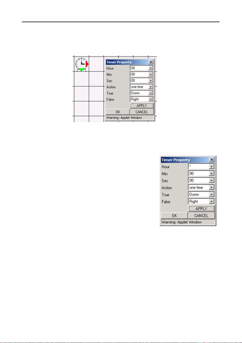
Creation and a Display of a Processing Task
(13) Timer: Execute at specified time.
External view Properties dialog box
of the component
Figure 7.36. Timer
- Hour: Specify the hour. Specify a value between 00 and 23.
Selecting [*] specifies that the action is performed
every hour.
- Min: Specify the minute.
Specify a value between
00 and 59. Selecting [*]
specifies that the action is
performed every minute.
- Sec: Specify the second.
- Action: Select the action to
[every times]: Branch to [True] whenever the condition is true.
[one time]: Execute once then do not branch to [True] again
Specify a value between
00 and 59. Selecting [*]
specifies that the action is
performed every second.
perform at the specified time.
until the condition becomes [False].
Figure 7.37. Example of a Timer setting
The settings shown on the right are used to execute once only at
every hour on the hour.
SVR-MMF(FIT) 83
Page 97
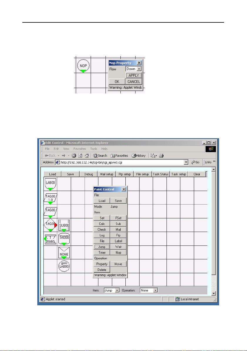
Creation and a Display of a Processing Task
(14) Nop: With no processing
External view Properties dialog box
of the component
Figure 7.38. Nop
- Does not perform any operation. Used to link from one
component to another.
Creation screen image
Figure 7.39. Creation screen
SVR-MMF(FIT)84
Page 98
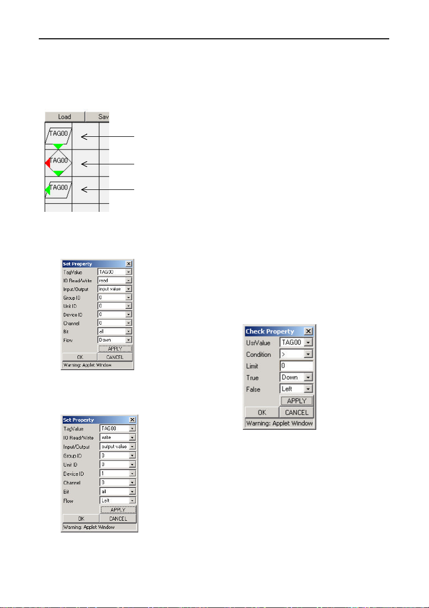
Creation and a Display of a Processing Task
Sample
Sample 1
Output data to a different channel when the value is non-zero.
(1)
(2)
(3)
Figure 7.40. Sample 1
(1) Read the collected data into TAG
number 00
Figure 7.41. Set Property
(3) Output the data from TAG number
00 to channel 0 of device 1.
(2) If the value of TAG number 00 is
greater than zero, perform the step
below. Otherwise perform the step
on the left. If control moves to a
location outside the frame,
processing jumps back to the
initial instructions at (0, 0).
Figure 7.42. Check Property
Figure 7.43. Set Property
SVR-MMF(FIT) 85
Page 99
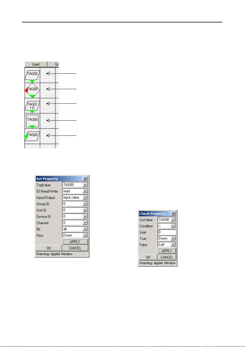
Creation and a Display of a Processing Task
Sample 2
When a value is non-zero, increment by one then output data to a different
channel.
(1)
(2)
(3)
(4)
(5)
Figure 7.44. Sample 2
(1) Read the collected data into TAG
number 00
Figure 7.45. Set Property
SVR-MMF(FIT)86
(2) If the value of TAG number 00 is
greater than zero, perform the step
below. Otherwise perform the step
on the left. If control moves to a
location outside the frame,
processing jumps back to the
initial instructions at (0, 0).
Figure 7.46. Check Property
Page 100
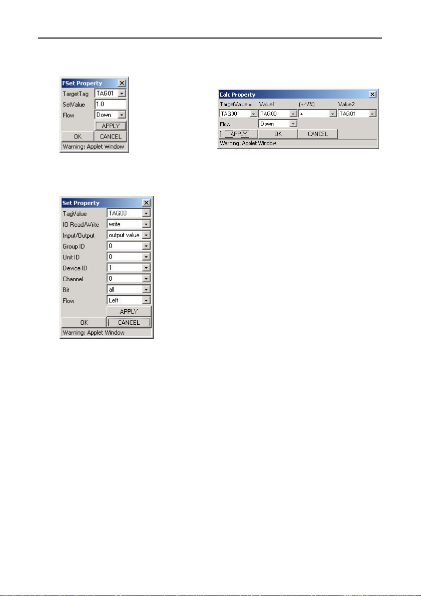
Creation and a Display of a Processing Task
(3) Set the value of TAG number 01 to
1.
Figure 7.47. FSet Property
(5) Output the data from TAG number
00 to channel 0 of device 1.
Figure 7.49. Set Property
(4) Add the value of TAG number 00
to TAG number 01 and set the
result in TAG number 00.
Figure 7.48. Calc Property
SVR-MMF(FIT) 87
 Loading...