

Page 1

F&eIT Series
10/100/1000M AUTO-MDIX
Industrial switchingHUB
For DIN rail, 8 ports
SH-9008H-FIT
User’s Manual
CONTEC CO., LTD.
Page 2
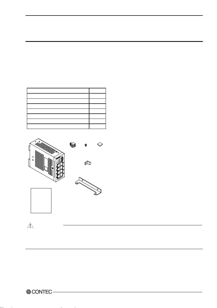
Name
Pcs.
Unit 1 Setup Guide
1
Acceptable connector
1
Connecto r omis sio n pre vent io n meta l fitt ings
1
Flat putting fixing bracket
2
Fixed screw M3×6
5
Rubber foot
4
x 2
x 5 x 4
Setup Guide
Unit
Acceptable
connector
Fixed
screw
Flat putting
fixing bracket
Connector omission
preventi on metal fi ttings
Rubber
foot
CAUTION
Check Your Package
Thank you for purchasing the CONTEC product.
The product consists of the items listed below.
Check, with the following list, that your package is complete. If you discover damaged or missing
items, contact your retailer.
Product Configuration List
* The manu al of this product can be downloaded from CONTEC homepage (http://www.contec.com/) free of charge.
To operate this product, a power supply (12-24VDC±5%) is required sep arat el y.
For power supply, see Chapter 3, Nomenclature of unit Components and Th eir Settin gs, “About of
Power Supply”.
SH-9008H-FIT
i
Page 3

Copyright
Copyright 2016 CONTEC CO., LTD . ALL R IGH TS RE S ER VED
No part of this document may be copied or reproduced in any form by any means without prior written
consent of CONTEC CO., LTD.
CONTEC CO., LTD. makes no commitment to update or keep current the information c ontained in
this document. The information in this document is subject to change without notice.
All relevant issues have been considered in the preparation of this document. Should you notice a n
omission or an y q uestionable item in this document, please feel fre e to noti f y CONTEC C O., LTD.
Regardless of the foreg oi n g statem en t, C ONTEC a ssum es no resp onsi bi lit y for an y error s tha t ma y
appear in this document or for results obtained by the user as a result of using this product.
Trademarks
Other brand and product names are trademarks o f t heir respective holder.
SH-9008H-FIT
ii
Page 4

Table of Contents
Check Your Package ............................................................................................................................ i
Copyright ............................................................................................................................................ ii
Trademarks ......................................................................................................................................... ii
Table of Contents ............................................................................................................................... iii
1. Before Using the Product 1
About the Unit .................................................................................................................................... 1
Features ........................................................................................................................................ 1
Customer Support ............................................................................................................................... 2
Web Site ....................................................................................................................................... 2
Limited One-Year Warranty ............................................................................................................... 2
How to Obtain Service........................................................................................................................ 2
Liability ............................................................................................................................................... 2
Safety Precaution s .............................................................................................................................. 3
Safety Information ....................................................................................................................... 3
Handling Precautions ................................................................................................................... 3
Environment ................................................................................................................................. 5
Inspection ..................................................................................................................................... 5
Storage ......................................................................................................................................... 5
Disposal........................................................................................................................................ 5
2. Setup of Hardware 7
Mounting or Removed DIN rail ......................................................................................................... 7
Mounting on a DIN rail ............................................................................................................... 7
Removed DIN rail ........................................................................................................................ 8
Mounting of Flat putting fixing bracket and rubber foot ................................................................. 11
Mounting .................................................................................................................................... 11
Mount of connector omission prevention metal fittings .................................................................. 13
Mounting .................................................................................................................................... 13
Installation Conditions ...................................................................................................................... 14
Installation orientation ............................................................................................................... 14
Spacing between th e system unit and any surroundin g objects ................................................ 17
3. Nomenclature of unit Components and Their Settings 19
Name of unit Components and Fun ct ion .......................................................................................... 19
4. Connecting to a Network 21
Network Cables ................................................................................................................................. 21
SH-9008H-FIT
iii
Page 5

Connecting a Personal Computer, another HUB unit or bridge ....................................................... 21
Connection Restrictions with 100BA SE-TX Repeater HUBs .................................................. 22
Connection Restrictions with 10B AS E-T Repeater HUBs ....................................................... 22
5. System Reference 23
Specification ..................................................................................................................................... 23
Physical Dimensions ......................................................................................................................... 25
Differences from SH-9008-FIT ........................................................................................................ 26
SH-9008H-FIT
iv
Page 6

1. Before Using the Product
1. Before Using the Product
This chapter provides information you should know before using the product.
About the Unit
SH-9008H-FIT is a compact -sized [39(W) × 120(D) × 94(H) mm] industria l switching HUB unit that
is compliant with the IEEE802.3ab (1000BASE-T)/IEEE802.3u (100BASE-TX)/IEEE802.3
(10BASE-T) standards.
Its features include Jumbo Frame support, AutoMDI/MDI-X, auto-negotiation, and aut omati c p ower
adjusting functi on. Th e aut omat ic p ower ad ju sti n g funct ion can redu ce th e p ower c on sumpti on b y up
to 60%. *1
With fan less configuration, SH-9008H-FIT is suit ab le for plac es wh ere si len ce is required. In
addition, the adoption of metal casing with great radiation performance enables the unit to be used in
ambient temperatures of 0 to 50°C. A DIN rail mounting mechanism and the mounting brackets
provided with the unit enable various types of installation.
Please read this manua l ca refu ll y so that you can b ui ld a syst em b y conn ectin g the s witch in g HUB uni t
to external d ev ices.
Features
- Compact-sized (39 (W) × 120 (D) ×94 (H) mm) unit equipped with 8 ports capable of 1000BASET
The compact-sized unit en clo su re (3 9 (W) ×120 (D) ×94 (H) mm) is equipped with the 8 ports that
are compliant with IEEE802.3ab (1000BASE-T)/IEEE802.3u (100BASE-TX)/IEEE802.3
(10BASE-T).
With fan less configuration, this product is sui tab le fo r pla c es where s i le nce is required. In
addition, the adopti on of meta l casin g with gr eat rad ia ti on per form anc e pro vid es th e operat in g
ambient temperature of 0 to 50°C.
- For jumbo frame
It is compatible with Jumbo Frame that increases transfer rate. C onn ection with Jumbo Frame
compatible devices increases d ata transfer ra te and contributes to increased transfer rat e and
reduced CPU load.
- Auto MDI/MDI-X feature, auto-n eg otiati on f eature
The Auto MDI/MDI-X feature can automatically recognize the cable type, st raigh t-through cable
or crossover cable, to prevent problems using the wrong cable type.
Also, the auto-nego t iation featur e can automatically recognize and choose the best communication
rate (10/100/1 000Mbps) and method (half/full duplex) available.
- Automatic power adjusting function
This function can automatically adjust the power consumption of unus ed ports, enab ling reduced
power consumption by up to 60% . * 1
- Flexible installation ori entati on.
The unit is equipped with a 35mm DIN rail mounting mechanism as standard. Also, the mounting
brackets provided with the unit make installation in any ori entati on pos sible (f loor, ceilin g, etc. ).
- Capable of running on a wide range of input voltages (12 to 24VDC)
The unit will function normally even if input voltage fluctuat es with in th e acc eptab le ran g e. In
addition, th e power connector includes an FG terminal.
*1 The comparison result of measur ed va lue s whe n a ll (e ig ht ) po rt s are in o per ation with t ho se w he n all ( e ig ht) ports are u nus ed .
SH-9008H-FIT
1
Page 7

1. Before Using the Product
Customer Support
CONTEC provides the following support services for you to use CONTEC products more efficiently
and comfortably.
Download the latest d riv ers from CO NTEC ’s Web s it e to use. In addition, as documents such as
precautions are also provided on the Web site, have a look on CONTEC’s Web site.
Web Si t e
Japanese http://www.contec.co.jp/
English http://www.contec.com/
Chinese http://www.contec.com.cn/
Latest product information
CONTEC provides up-to-date information on products.
CONTEC also provides product manuals and various technical documen ts in th e P DF.
Free download
You can download updated driver software and differential fi les as well as sample programs ava ilable
in several languag es.
Note! For product information
Contact your retailer if you h ave any technical question ab out a CONTEC product or need its price,
delivery time, or est imat e in fo rmati on .
Limited One-Year Warranty
CONTEC F&eIT products are war ra nt ed by CO NTEC CO. , LTD. t o be free f rom defect s in mater ia l
and workmanship for up to one year from the date of purchase by the original purchaser.
Repair will be free of cha rg e onl y wh en this product is returned freight prepai d wi th a c opy of th e
original invoice and a Return Merchandis e Authorization t o the distributor or the CONTEC group
office, from which it was purchased.
This warranty is not app licab le f or s crat ch es or nor ma l wear , but on ly for th e elec tr onic ci rcu itry and
original products. The warranty is not applicable if the device has been tamper ed with or damag ed
through abuse, mistreatment, neglect, or unr easonable use, or if the original invoice is not included, in
which case repairs wi ll be c onsid ere d bey ond th e wa rrant y p olic y.
How to Obtain Service
For replacement or r epai r, ret u rn the d evic e frei ght p r epaid , with a cop y of th e orig in al in voic e. Plea s e
obtain a Return Merchandise Authorization Number (RMA) from the CON TEC gr oup of fic e wher e
you purchased before returning any product.
* No product will be accepted by CONTEC group without the RMA number.
Liability
The obligation of th e warran to r is so lely t o repai r o r rep lace th e p roduct . In no even t will th e
warrantor be liable for any incidental or consequential damages due to such defect or consequences
that arise fro m inexperienced usage, misuse, or malfunction o f this device.
SH-9008H-FIT
2
Page 8

1. Before Using the Product
DANGER
WARNING
C
AUTION
DANGER
CAUTION
Safety Precautions
Understand the following definitions and precautions to use the produ ct safely.
Safety Information
This document provides safety information using the following symbols to prevent accidents resulting
in injury or death and the destruction of equipment and resources. Understand the meanings of these
labels to operate th e equip m ent saf el y.
DANGER indicates an imminently hazardous situation which, if not avoided, will
result in death or serious injury.
WARNING indicates a potentially hazardous situation which, if not avoided, could
result in death or serious injury.
CAUTION indicates a potentially hazardous s ituation which, if not avoided, may
result in minor or moderate injury or in property damage.
Handling Precautions
Do not use the product where it is exposed to flammable or corrosive gas. Doing so may result in
an explosion, fire, el ect ric sh ock, or fai lure.
- The link speed value (e.g., 1000Mbps) of the transmission rate used in the Manual (this document) is
the theoretical maximum value of the wired LAN standard and do not indicate the actual data
transmission speed.
- The frame loss could occur depending on the connection destination or installed environment.
- When attempt is made to perform communication for devices that are not Jumbo Frame
compatible, communi cat i on effi ci enc y ma y drop extremely. There are also cases where
communication is disconnected.
- As this product contains precision electronic components, do not use or store magnetic field or
radio waves. They may cause the malfunction, heat generation, fault, or damage.
- Do not use or store the equipment in a hot or cold place, or in a place that is subject to severe
temperature changes. They may cause the malfunction, heat generation, fault, or damage.
- Do not use or store the equipment in a place subject to direct sunlight or near a heating device,
such as a stove. And do not use or store the product near equipment generating a strong magnetic
field or radio waves. They may cause the malfunction, heat genera tion, fault, or damage.
- Do not use or store this product in the presence of chemic a ls.
- Do not use this product in extremely humid or dusty locations. It is extremely dangerous t o use
this product with its interior penetrated by water or any other fluid or conductive dust. If this
product must be used in such an environment, install it on a dust-proof control panel, for example.
SH-9008H-FIT
3
Page 9

1. Before Using the Product
This equipment ha
s been tested and found to comply wi
th the limits for a Class A digital
device,
p
ursuant to part 15 of the FCC Rules.
Thes
e limits are designed to provide re
asonable protection
ag
ainst harmful interference w
hen the equipment is operat
ed in commercial enviro
nment.
T
his equipment generates, us
es, and can radiate
radio frequen
cy energy and, if not instal
led and
used i
n accordance with the
in
struction m
anual, may cause h
armful interference to
radio
com
munications. Operation
of th
is equipment in a res
idential
area is likely to
cause harmful
interferen
ce at his
own expense.
NOTE
Change or modifi
cations not expressly approv
ed the manufacturer can vo
id the us
er'
s authority to
operate this equipment
.
WARNING TO USER
- If you noticing abnormal odor or overheat, please unplug the power cord immediately.
- When you find faults or abnormalities (bad smell or excessive heat), pull the power cord off, then
contact the shop you bought the product or our information center.
- The product could be very hot in the operation. Please do not touch by hands or body. It may
cause burns.
- To avoid electric shock, please do not touch the system with a wet hand.
- Do not open the unit casing. CONTEC will disclaim any responsibility for equipment whose casing
has been opened.
- Do not modify the unit. CONTEC will bear no responsibility for any problems, etc., resulting from
modifying this unit.
- To clean this product, gently wipe it wi th a soft cloth soaked with water or a neut ra l det ergen t. D o
not use benzene, a thinner, or other volatile solvents as they can cause the coating to discolor or
peel off.
- Do not modify the product. CONTEC will bear no responsibility for any problems, etc., resulting
from modifying this product.
- If you move or transfer the p r o d u ct, make sure to attach the Setup Guide (thi s document).
- To use the product in places affected by overcurr ent or overvo lt ag e (li ghtni ng su rge, etc. ), s elect
appropriate surge protection device (SPD) for all entry paths (power line, LAN, ground, etc.). For
selection/introducti on /installation of SPD, please consult a specialist.
- Regardless of th e fo regoi n g stat emen ts , CON TEC is not liab le f or an y da mages what s oever
(including damages for loss of business profits) arising out of the use or inability to use this
CONTEC product or the information contained herein.
FCC PART15 class A Notice
SH-9008H-FIT
4
Page 10

1. Before Using the Product
1
3
5
7
2
4
6
8
i
i
+
V
V
POWER
12-24VDC
FG
( )
* The ventilation slits are not covered, and neither dust
nor ali en substanc e is attached to the venti lation sl its.
Environment
Use this product in the following environment. If used in an unauthorized environment, the board may
overheat, malfunc ti on, or caus e a fail ur e.
Operating temperatu re
0 - 50° C
Operating humidity
10 - 90%RH (No condensation)
Corrosive gases
None
Floating dust particles
Not to be excessive
Inspection
Inspect the product periodically as follows to use it safely.
* The ventilation slits are not covered, and neither dust
nor alien substance is attached to the ventilation slits.
Storage
When storing this product, keep it in its original packing form.
(1) Put the unit in the storage bag.
(2) Wrap it in the packing material, th en put it in the box.
(3) Store the package at room temperature at a place free f rom di rect sun li ght , m oistu re, sh ock,
vibration, magnet ism , and st ati c el ectr ici t y.
Disposal
When disposing of the product, follow the disposal procedures stipulated under the relevant laws and
municipal ordinances.
SH-9008H-FIT
5
Page 11

1. Before Using the Product
SH-9008H-FIT
6
Page 12

2. Setup of Hardware
2. Setup of Hardware
Mounting or Removed DIN rail
Mounting on a DIN rail
(1) Hook the clips on the upper DIN rail fixation metal fittings to the groove on the upper DIN rail,
then push the lower part of the product to the DIN rail.
Figure 2.1. Mounting on a DIN rail < 1 / 2 >
(2) The Latch metal fittings is automatically locked, and the unit can be mounted in one-touch.
Figure 2.2. Mounting on a DIN rail < 2 / 2 >
SH-9008H-FIT
7
Page 13

2. Setup of Hardware
WARN
IN
G
Removed DIN rail
A Phillips-head s c rew dri ver o r a flat h ead sc rew d river i s req ui red to r emov e the unit from the DIN
rail.
Remove LAN cab l es and power cabl es connected to the unit before r emoval from the DIN rail.
For a Phillips-head screw driver
(1) Push a phillips-head screw driver (diameter: 6-7mm ) into the lat ch metal fi ttin g on th e lower part
of product. Do not put too much force in doing that. The DIN rail fixation metal fittings or the
product may be damaged .
Figure 2.3. Removing the unit from the DIN rail with phillips-head screw driver < 1 / 3 >
(2) The latch metal fitting is pushed do wn and th e produ ct can b e remo ved fr om th e D IN rail.
Figure 2.4. Removing the unit from the DIN rail with phillips-head screw driver < 2 / 3 >
SH-9008H-FIT
8
Page 14

2. Setup of Hardware
(3) By lifting the uni t, you can ea si ly rem ove it f rom th e D IN rail.
Figure 2.5. Removing th e u ni t from the DIN rail with phillips-head screw driver < 3 / 3 >
For a flathead screw dri ver
(1) Push the flathead screw driver (tooth width 5.5 - 7mm) into the latch metal fitting at the lo wer
section of the unit, and th en push it down vertically.
Do not put too much force in doing that. The DIN rail fixation metal fittings or the product may be
damaged.
Figure 2.6. Removing the unit f rom the DIN ra il with flathead screw driver < 1 / 3 >
(2) The latch metal fitting is pushed down and the product can be removed from the DIN rail.
Figure 2.7. Removing the unit from the DIN rail with flathead screw driver < 2 / 3 >
SH-9008H-FIT
9
Page 15

2. Setup of Hardware
(3) By lifting the uni t, you can ea si ly rem ove it f rom th e D IN rail.
Figure 2.8. Removing the unit from the DIN rail with flathead screw driver < 3 / 3 >
SH-9008H-FIT
10
Page 16

2. Setup of Hardware
Mounting of Flat putting fixing bracket and rubber foot
Mounting
Remove the four location screws used for fixing the unit and the DIN rail mounting brackets, and then
remove the DIN rail mount in g brac k ets fr om th e unit. Thi s op eration is performed for both flat putting
fixing brackets an d rub b er feet.
Figure 2.9. Removed of DIN rail fixing bracket
Flat putting fixing bracket
Fixes the unit with screws supplied with this product.
Figure 2.10. Mounting of fl at putting fixing bracket
SH-9008H-FIT
11
Page 17

2. Setup of Hardware
Rubber foot
Align wi t h th e fou r corners on the unit ov ervi e w level s id e, and m ount t h e rubber feet supp li ed with
this product.
Figure 2.11. Mounting of rubber foot
SH-9008H-FIT
12
Page 18

2. Setup of Hardware
Mount of connector omission prevention metal fittings
Mounting
(1) Connect an appropriat e connector to the power connector, mount the connector detaching
prevention metal fitting.
Figure 2.12. Mount of connector omission prevention metal fittings
SH-9008H-FIT
13
Page 19

2. Setup of Hardware
(Top)
(Bottom)
(Bottom)
W
AR
N
I
N
G
1
3
5
7
2
4
6
8
i
i
+VV
POWER
12-24VDC
FG
( )
1
3
5
7
2
4
6
8
135
7
246
8
135
7
246
8
i
i+
V
V
POWER
12-24VDC
FG
( )
ii+V
V
POWER
12-24VDC
FG
( )
i
i+
V
V
POWER
12-24VDC
FG
( )
Ceil
ing
Floor
Installation Conditions
Even within the temp eratu re sp eci fic ati on ra n ge, make su re th e heat in th e unit can let off
adequately in the case o f hi gh temp eratu r e envi ron ment application.
Installation orientation
When DIN rail mounted
Avoid installation on unsuitable insta llation directions as insufficient heat dissipation may occur.
Suitable
installation
directions
(Top)
Unsuitable
installation
directions
(Bottom)
(Top)
Figure 2.13. Installation direction (when the DIN rail fixing brackets mounted)
SH-9008H-FIT
14
Page 20

2. Setup of Hardware
(Top)
1
3
5
7
2
4
6
8
1
3
5
7
2
4
6
8
i
i
+
V
V
POWER
12-24VDC
FG
( )
i
i
+VV
POWER
12-24VDC
FG
( )
Wall
Wall
Wall
Wall
POWER
12-24VDC
12-24VDC
Ceiling
Floor
Flat putting fixing bracket mounted
Installation in all directions is possible if flat putting fixing brackets are mounted. However, as heat
dissipation may be not adequate compa red with ins ta llat i on in oth er di rect i ons, k eep th e di stanc e f rom
surrounding objects as long as possible in cas e of high temperature environment application.
Suitable
installation
directions
(Bottom)
(Top)
(Bottom)
Figure 2.14. Installation direction (when flat putting fixing brackets mounted)
SH-9008H-FIT
15
Page 21

2. Setup of Hardware
(Top)
(Bottom)
(Top)
(Bottom)
135
7
246
8
i
i+
V
V
POWER
12-24VDC
FG
( )
SH-9008H-F IT
Floor
1
3
5
7
2
4
6
8
135
7
246
8
1
3
5
7
2
4
6
8
ii+V
V
POWER
12-24VDC
FG
( )
ii+V
V
POWER
12-24VDC
FG
( )
SH-9008H-FI T
i
i
+
V
V
POWER
12-24VDC
FG( )
Floor Floor Floor
Floor Floor
Rubber foot mounted
Mount the rubber feet to install it if fixing brackets are n ot mounted in the case of horizontal
installation. Avoid installa ti on on unsuitable installation directions as this may cause insufficient heat
dissipation and overturning.
Suitable
installation
directions
Unsuitable
installation
(Bottom)
(Top)
directions
Figure 2.15. Installation direction (in the case of rubber feet)
16
SH-9008H-FIT
Page 22

2. Setup of Hardware
W
AR
NI
N
G
50 or more
1
3
5
7
2
4
6
8
7.5
100 or more
i
i
+VV
POWER
12-24VDC
FG
( )
50 or more
50 or more
50 or more50 or more
or more
[mm]
Spacing between the system unit and any surrounding objects
Do not locate the module in a fully enclosed housing.
DIN rail mounted
Secure a distance of at least 50mm between the top/bottom of the main unit and any surrounding
objects and also a dista nc e of at lea st 50mm bet ween each sid e of the un it and any su rr oundin g objec ts
(5.8mm for the unit overvi e w level sid e).
Figure 2.16. Spacing be tw een the system unit and any surrounding objects while the DIN rail mounted
SH-9008H-FIT
17
Page 23

2. Setup of Hardware
1
3
5
7
2
4
6
8
i
i
+
V
V
POWER
12-24VDC
FG
( )
50 or more
100 or more
50 or more
50 or more
50 or more
50 or more
50 or more
[mm]
When flat putting fixing brackets and rubber feet mounted
Secure a distance of at least 50/5.8mm between the top/bottom of the main unit and any surr ounding
objects and also a distance of at least 50mm between each side of the unit and any surrounding objects.
Figure 2.17. Spacing between the system unit and any surrounding objects while flat putting fixing brackets and rubber feet mounted
SH-9008H-FIT
18
Page 24

3. Nomenclature of unit Components and Their Settings
Name
Status
Color
Content of Display
POWER LED
POWER
Green
OFF : Power off
ON : Power on
LED:A
10Mbps
Yellow
OFF : No LINK
100Mbps
Green
ON : LINK
LED:B
1000Mbps
Green
Flashing : ACT(Data send/
receive)
Name
Function
Power supply
Acceptable connector(Appending):MC1,5/3-ST-3,5(PHOENIX CONTACT)
. (In the length of the cable, it is a
condition to fill the power supply specification.)
You can prevent connectors from being omitted by connector omission
Power Supply Connector
MC1,5/3-G-3,5 (PHOENIX CONTACT)
Pin Number
Signal
Description
1
Vi+
Power (12-24VDC±5%)
2
Vi-
Power(GND)
3
FG
Frame Ground
1
3
5
7
2
4
6
8
i
i
+VV
POWER
12-24VDC
FG( )
POWER LED
Power supply connector
LED: A
LED: B
10BASE-T/100BASE-TX/
1000BASE-T port
LED: A
LED: B
Vi+
Vi-
FG
12
3. Nomenclature of unit Components and
Their Settings
Name of unit Components and Function
Figure 3.1 shows t he nomenclature of unit components.
Figure 3.1. Names of unit Components
Table 3.1. LED Indicators
Table 3.2. Connectors
Connector
SH-9008H-FIT
The correspondence cable is AWG28-16
prevention metal fittings. You can connect cables by screw cramps.
- 24VDC
19
Page 25

3. Nomenclature of unit Components and Their Settings
Name
Function
10BASE-T/
Ports 1 - 8
and other HUB units and
Use connector
JC0-0182NL(Pulse)
Pin name
Signal
Description
1
TRD+(0 )
Data0 is transmitted and received(+)
2
TRD-(0)
Data0 is transmitted and received(-)
3
TRD+(1 )
Data1 is transmitted and received(+)
4
TRD+(2 )
Data2 is transmitted and received(+)
5
TRD-(2)
Data2 is transmitted and received(-)
6
TRD-(1)
Data1 is transmitted and received(-)
7
TRD+(3 )
Data3 is transmitted and received(+)
8
TRD-(3)
Data3 is transmitted and received(-)
1
8
Input voltage (V)
Time (ms)50
25.2
24
12
11.6
Table 3.3. 10BASE-T/100BASE-TX/1000BASE-T port
100BASE-TX/
1000BASE-T port
This is the port for connecting the PC (LAN adapter)
bridges.
Auto-negotiation of communication rates (10Mbps/100Mbps/1000Mbps), and
communication methods(Half/Full duplex). By Auto MDI/MDI-X function,
straight cable and the cross cable are recognized automatically.
About of P o wer S upply
For power supply, use the power supply that rises within an input voltage range of 11.6VDC or higher
within 50msec. The power supply that cannot m eet this requirement may cause devic e fai lu re or
accident.
Figure 3.2. Graph of Rise Time of Power Supply
SH-9008H-FIT
20
Page 26

4. Connecting to a Network
WA
RNING
SH-9008H-FIT
CPU-CA20(FIT)GY,
CPU-CA10(FIT)GY .,etc
Straight or cross c ables
4. Connect i ng t o a Ne tw or k
Network Cables
Cables meeting the following specifications should be used:
- 10BASE-T : Equal to greater than Category 3 UTP, STP cable 100 m or le ss
- 100BASE-TX : Equal to greater than Category 5 UTP, STP cab le 100 m or less
- 1000BASE-T : Equal to greater than Category 5e UTP, STP cab le 100m or less
- There are straight/ cr oss U TP and STP cab les. Aut o MD I/MD I-X feat u re a llows c onnec t i on of
your Switching HUB unit to a personal computer (LAN adapter) or another HUB unit and a
bridges using either a straight or cross cable.
Connecting a Personal Computer, another HUB unit or bridge
When connecting the Switching HU B unit to a personal comput er, an F&e IT seri es con t oroller uni t,
another HUB unit or a bridge, use any 10BASE-T/100BASE-TX/1000BASE-T port and either a
straight or cross cab le.
When using Jumbo Frame, it is necessary for other network devices of the communication partner,
such as LAN adapters, t o be Jumb o Fra me comp ati b le.
Figure 4.1. An example for connection with PC or other HUBs and control modules
SH-9008H-FIT
21
Page 27

4. Connecting to a Network
SH-9008H-FIT
(1) (2)
- Use UTP and STP cables with category 5 or higher for cables (1)(2)(3).
- The total length of cables (1)(2)(3) should be set to 205m or less.
- The length of cable (2) should be 5m or less.
100BASE-TX HUB(Cl ass II)
(3)
100BASE-TX HUB(Cl ass II)
SH-9008H-FIT
10BASE-T HUB
Connection Restrictions with 100BASE-TX Repeater HUBs
Cascade connecti on with 100B ASE-TX repeater HUBs at Class I is possible. Up to two stages of
cascade connect ion between 100BASE-TX Class II repeaters i s possible. In addition, the total
maximum cable length of cab les (1)( 2)(3 ) is 205 m or l ess . For d etai ls, s ee the operat i on manual o f
your100BASE-TX repeater HUB.
Figure 4.2. Connection restrictions with 100BASE-TX repeater HUB (Class II)
Connection Restrictions with 10BASE-T Repeater HUBs
As many as four stages of 10BASE-T repeater HUBs can be connected using cascade connection. In
addition, the maximum length of UTP and STP cables between cascad ed HUBs i s 100m . For d etai ls,
see the operation manual of your 10BASE-T repeater HUB.
Figure 4.3. Connection restrictions with 10BASE-T repeater HUBs
SH-9008H-FIT
22
Page 28

5. System Reference
Item
Specification
Ethernet standards
IEEE802.3/IEEE802.3u /IEEE802.3ab –compliant
Data transfer rate
10Mbps/100Mbps/1000Mbps (auto-negotiation)
Access method
CSMA/CD
Communications method
All ports: Full/Half duplex (auto-negotia tion)
Topology
Star topology
Half Duplex :Back pressure
Number of effective ports
8
Address table
8,192 entries
Jumbo fra me*1
9.6Kbyte
Buffer capacity
512Kbyte
Aging time
300sec (Max.)
100M(Green), LINK/ACT 1000M( Green)
Power supply voltage
12V - 24VDC±5%
FG pin
Power supply connector equipped with FG pin
Power consumption (Max.)
When inputting 12V : 0.65A, When inputting 24V : 0.35A
Physical dimensions (mm)
39(W) x 120(D) x 94(H) (exclusive of protrusions)
the flat putting fixing bracket is installed)
Module installation method
One-touch attachment of a 35mm DIN rail. (Mounting
e flat putting fixing
5. System Reference
Specification
Table 5.1. Specifications
Flow control Full Duplex : IEEE802.3x compliant flow control
Switching method Store and forward
LED indicator POWER(G reen), LINK/ACT 10M(Yellow), LINK/ACT
Weight 360g (410g when the DIN rail fixation metal fittings(standard) or
mechanism is equipped with the main body as standard),
Fixation with the mounting phase by using th
bracket and rubber feet.
When using Jumbo Frame, it is necessary for other network devices on the communication route to
*1
be Jumbo Frame compatible.
SH-9008H-FIT
23
Page 29

5. System Reference
Operating temperature
0 - 50°C
Storage temperature
-10 - 60°C
Floating dust particles
Not to be excessive
Corrosive gases
None
Line-noise
AC line/2kV, Signal lin e/1kV (JIS C61000-4-4Level 3, EN61000-4-4Level 3)
Static electricity
resista nce
Contact discharge/4kV (JIS C61000-4-2Level 2, EN61000-4-2Level 2)
Atmospheric discharge/8kV (JIS C61000-4-2Level 3, EN61000-4-2Level 3)
(JIS C60068-2-6-compliant, IEC60068-2-6-compliant)
Impact resistance
15G, half-sine shock for 11ms in X, Y, and Z directions
Grounding
Class D grounding (previous class 3 grounding)
Table 5.2. Installation Environment Requirements
Item Specification
Humidity 10 - 90%RH(No condensation)
Line-Noise
resista nce
Vibration
resista nce
Sweep resistance
10 - 57Hz/semi-amplitude 0.15mm,57 - 150Hz/2.0G
40minutes each in X, Y, and Z directions
(JIS C60068-2-27-compliant, IEC60068-2-27-compliant)
SH-9008H-FIT
24
Page 30

5. System Reference
39
94
120
6.5
1
3
5
7
2
4
6
8
47
(9)
i
i
+
V
V
12-24VDC
FG( )
[mm]
39
94
119
1
3
5
7
2
4
6
8
45
25
70
10
100
108
118
4-φ4
i
i
+
V
V
12-24VDC
FG
( )
[mm]
Physical Dimensions
Figure 5.1. Physical dimens ions when Din rail fixation metal fittings (standard) are installed
Figure 5.2. Physical dimensions when flat putting fixing brackets is installed
SH-9008H-FIT
25
Page 31

5. System Reference
Differences from SH-9008-FIT
SH-9008H-FIT, the high er-grade model of the conventional SH-9008-FIT, has the main differences as
follows:
SH-9008-FIT SH-9008H-FIT
Capacity of buffer 176Kbyte 512Kbyte
Power consumption (Max.) For 12V input : 0.6A,
For 24V input : 0.4A
For 12V input : 0.65A,
For 24V input : 0.35A
SH-9008H-FIT
26
Page 32

Page 33

SH-9008H-FIT
User’s Manual
CONTEC CO., LTD. May 2016 Edition
3-9-31, Himesato, Nishiyodogawa-k u, Osak a 555 -0025 , Japan
Japanese http://www.contec.co.jp/
English http://www.contec.com/
Chinese http://www.contec.com.cn/
No part of this document may be copied or reproduced in any form by any means without prior written
consent of CONTEC CO., LTD.
[05252016] Management No. NA05016
Parts No. LYTZ191
 Loading...