

Page 1

PC-HELPER
Digital Output Board
with Relay-Isolation for PCI
RRY-16C(PCI)H
RRY-32(PCI)H
User’s Guide
CONTEC CO.,LTD.
Page 2
Check Your Package
Thank you for purchasing the CONTEC product.
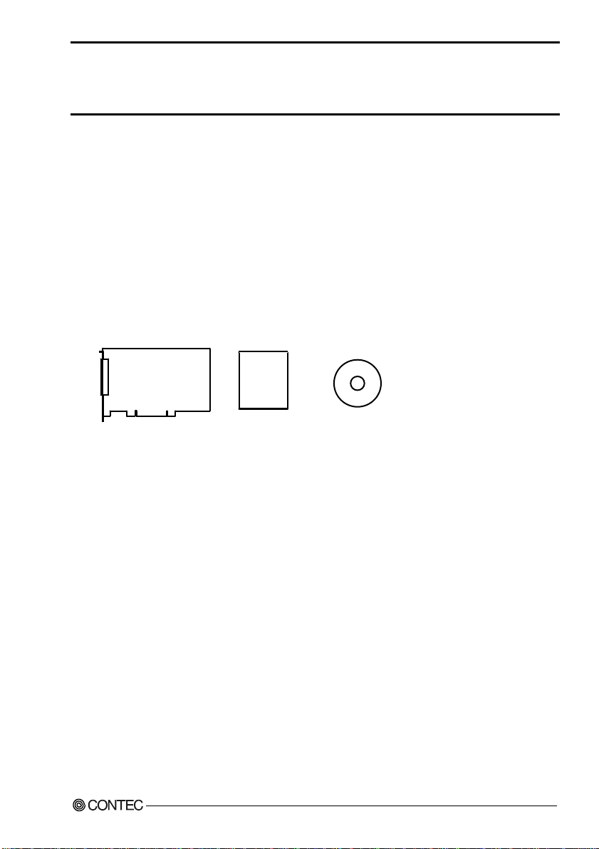
The product consists of the items listed below.
Check, with the following list, that your package is complete. If you discover damage d or missing item s,
contact your retailer.
Product Configuration List
- Board (One of the following)
[RRY-16C(PCI)H or RRY-32(PCI)H] …1
- First step guide …1
- CD-ROM*1 [API-PAC(W32)] …1
*1 The CD-ROM contains the driver software and User’s Guide (this guide).
Board
RRY-16C(PCI)H, RRY-32(PCI)H
First step guide
CD-ROM
[API-PAC(W32)]
i
Page 3

Copyright
Copyright 2005 CONTEC CO., LTD. ALL RIGHTS RESERVED
No part of this document may be copied or reproduced in any form by any means without prior written
consent of CONTEC CO., LTD.
CONTEC CO., LTD. makes no commitment to update or keep current the information contained in this
document. The information in this document is subject to change without notice.
All relevant issues have been considered in the preparation of this document. Should you notice an
omission or any questionable item in this document, please feel free to notify CONTEC CO., LTD.
Regardless of the foregoing statement, CONTEC assumes no responsibility for any errors that may
appear in this document no r for re sult s obt ain ed by th e use r as a resu lt of usi ng th is produ ct .
Trademarks
MS, Microsoft, Windows, Windows NT and MS-DOS are trademarks of Microsoft Corporation. Other
brand and product names are trademarks of their respective holder.
ii
RRY-16C(PCI)H, RRY-32(PCI)H
Page 4

Table of Contents
Check Your Pack ag e............................................................................................................................i
Copyright ............................................................................................................................................ ii
Trademarks .........................................................................................................................................ii
Table of Con tents...............................................................................................................................iii
1. BEFORE USING THE PRODUCT 1
About the Bo ards................................................................................................................................ 1
RRY-16C(PCI ) H Features........................................................................................................... 1
RRY-32(PCI)H Fe at u re s ............................................................................................................. 1
Support Softw ar e ......................................................................................................................... 2
Cable & Connect or ( Op ti on ) ...................................................................................................... 3
Accessories ( Op tio n ) .................................................................................................................. 3
Customer Supp o rt ............................................................................................................................... 4
Web Site....................................................................................................................................... 4
Limited Thre e -Y ea rs Wa r ra nt y .......................................................................................................... 4
How to Obtain Serv ic e ....................................................................................................................... 4
Liability............................................................................................................................................... 4
Safety Precau t ion s .............................................................................................................................. 5
Safety Infor mat i on ....................................................................................................................... 5
Handling Pre ca u tio n s................................................................................................................... 6
Environment................................................................................................................................. 7
Inspection..................................................................................................................................... 7
Storage ......................................................................................................................................... 7
Disposal ....................................................................................................................................... 7
2. SETUP 9
What is Setup? .................................................................................................................................... 9
Using the Board un de r W in do w s Us in g th e D riv e r Lib ra r y A PI -PAC ( W 3 2) ............................ 9
Using the Board under Windows Using Software Other than the Driver Library
API-PAC(W32 )............................................................................................................................ 9
Using the Board un d er an OS O th e r th an Wi n do w s ................................................................. 10
Step 1 Installi n g the Software .......................................................................................................... 11
Starting the I ns t all P r og r a m....................................................................................................... 11
Selecting the Di git a l I/ O Dr iv er ................................................................................................12
Executing the In s tal l a tio n .......................................................................................................... 13
Step 2 Setting th e H ar d wa r e ............................................................................................................. 14
Parts of the Bo ard an d F ac to r y D ef au l ts ................................................................................... 14
Setting the Bo ard ID .................................................................................................................. 16
Plugging the Board .................................................................................................................... 17
RRY-16C(PCI)H, RRY-32(PCI)H
iii
Page 5

Step 3 Installi ng th e H ard w a re .........................................................................................................18
Turning on the PC...................................................................................................................... 18
Setting with th e Fou n d Ne w H a rd war e W iz a rd......................................................................... 18
Step 4 Initi alizing the Software ........................................................................................................ 21
Invoking API-TOOL Confi g uration.......................................................................................... 21
Updating the S e ttin g s................................................................................................................. 21
Step 5 Checking Op e r ati o n s w ith th e D i ag no s is P rog ra m ............................................................... 22
What is the Di agno s is P r og r a m?................................................................................................ 22
Check Method ............................................................................................................................2 2
Using the Di agnosis Program.................................................................................................... 23
Setup Troubl esh oo ti n g...................................................................................................................... 26
Symptoms and A cti o ns .............................................................................................................. 26
If your proble m c a nno t b e r eso lv ed...........................................................................................2 6
3. EXTERNAL CONNECTION 27
Using the On-board Connectors ....................................................................................................... 27
Connecting a D evi c e to Co n n e cto r ............................................................................................27
Connector Pin Ass i gnment ........................................................................................................28
Relationships be tw ee n AP I-P AC ( W32 ) Log ic a l Po rt s/ Bi ts a nd Co nn e cto r Sig na l Pin s..........29
Output Signal Co nn e c tio n ................................................................................................................. 30
Output Circuit ............................................................................................................................3 0
Connection to the LE D ..............................................................................................................31
4. FUNCTION 33
Data I/O Func tio n ............................................................................................................................. 33
Data Output.................................................................................................................... ............ 33
Monitoring Ou tp ut D at a ............................................................................................................. 33
iv
RRY-16C(PCI)H, RRY-32(PCI)H
Page 6

5. ABOUT SOFTWARE 35
CD-ROM Directo r y S t ru c tu re .......................................................................................................... 35
About Software for Windows..................................................................................................... ...... 36
Accessing the He lp F il e............................................................................................................. 36
Using Sample Programs ............................................................................................................ 37
Uninstalling the Dr i v er Li b ra rie s .............................................................................................. 39
About Software for Linux................................................................................................................. 40
Driver Softwa re In s tal l Pro c ed ur e ............................................................................................. 40
Accessing the He lp F il e............................................................................................................. 41
Using Sample Programs ............................................................................................................ 41
Uninstalling the driver............................................................................................................... 41
6. ABOUT HARDWARE 43
Hardware spe cification ..................................................................................................................... 43
Block Diagra m.................................................................................................................................. 4 5
Difference fr o m R RY -1 6 C( P C I) and RR Y -32 ( P CI )....................................................................... 4 7
RRY-16C(PCI)H, RRY-32(PCI)H
v
Page 7

vi
RRY-16C(PCI)H, RRY-32(PCI)H
Page 8

1. Before Using the Product
1. Before Using the Product
This chapter provides information you should know before using the product.
About the Boards
The < RRY-16C(PCI)H > and < RRY-32(PCI)H > are PCI bus-compliant interface boards that output
signals to lead relay contacts.
The < RRY-16C(PCI)H > provides up to 16 relay outputs.
The < RRY-32(PCI)H > provides up to 32 relay outputs.
Using the bundled driver library [API-PAC(W32)], you can create Windows application software for
this board in your favorite programming language supporting Win32 API functions, such as Visual Basic
or Visual C/C++.
RRY-16C(PCI)H Features
- Up to 16 reed relays w ith independently make contact output
- High-capacity output rating designed to be a maximum of 125 VAC/30 VDC, 2 A per channel
RRY-32(PCI)H Features
- 32 reed relays with a single make contact are implemented. These relays are classified into four
groups, each group (eight relays) sharing a minus common pin.
- Output ratings are designed for a maximum of 100VAC/100VDC and 500 mA per channel, a
maximum of 1A for each group (one group of eight channels share a minus common). Relay
contactor rating is 10VA(10W) maximum.
RRY-16C(PCI)H, RRY-32(PCI)H
1
Page 9

1. Before Using the Product
Support Software
You should use CONTEC support software according to your purpose and development environment.
Driver Library
API-PAC(W32) is the library software that provides the commands for CONTEC hardware products in the form of
Windows standard Win32 API functions (DLL). It makes it easy to create high-speed application software taking
advantage of the CONTEC hardware using various programming languages that support Win32 API functions, such as
Visual Basic and Visual C/C++.
It can also be used by the installed diagnosis progra m to check hardware operations .
CONTEC provides download services to supply the updated drivers an d differential files.
For details, read Help on the bundled CD-ROM or visit the CONTEC’s Web site.
< Operating environment >
OS Windows XP, 2000, NT, Me, 98, etc..
Adaptation language Visual C/C++, Visual Basic, Delphi, Builder, etc..
Others Each piece of library software requires 50 MB of free hard disk space.
API-PAC(W32)
Linux version of analog I/O driver
CD-ROM)
This driver is used to control CONTEC digital I/O boards (PC Cards) fro m within Linux.
You can control CONTEC I/O boards easily using the shared library used by gcc and Kylix, the device driver (module)
for each kernel version, and the board (PC Card) configuration program (config).
CONTEC provides download services to supply the updated drivers an d differential files.
For details, read Help on the bundled CD-ROM or visit the CONTEC’s Web site.
< Operating environment >
OS RedHatLinux, TurboLinux, etc..
(For details on supported distributions, refer to Help available after installation.)
Adaptation language gcc, Kylix, etc..
Others Requires 3 MB of free hard disk space.
Data acquisition VI library for LabVIEW
This is a VI library to use in National Instruments LabVIEW.
VI-DAQ is created with a function form similar to that of LabVIEW's Data Acquisition VI, allowing you to use
devices without complicated settings.
See http://www.contec.co.jp/vidaq/ for details and download of VI-DAQ.
(Bundled)
API-DIO(LNX)
VI-DAQ
(Supplied: Stored on the API-PAC(W32)
(Free download)
various
2
RRY-16C(PCI)H, RRY-32(PCI)H
Page 10

1. Before Using the Product
Cable & Connector (Option)
Flat cable with both-ends 37-pin D-SUB connector : PCB37P-1.5 (1.5m)
: PCB37P-3 (3m)
: PCB37P-5 (5m)
Shield cable with both-ends 37-pin D-SUB connector : PCB37PS-0.5P (0.5m)
: PCB37PS-1.5P (1.5m)
: PCB37PS-3P (3m)
: PCB37PS-5P (5m)
Flat cable with one-ends 37-Pin D-SUB connector : PCA37P-1.5 (1.5m)
:PCA37P-3 (3m)
:PCA37P-5 (5m)
Shield cable with one-end 37-pin D-SUB connector : PCA37PS-0.5P (0.5m)
:PCA37PS-1.5P (1.5m)
:PCA37PS-3P (3m)
: PCA37PS-5P (5m)
37pin D-SUB(male) connector Five-piece set : CN5-D37M
CAUTION
The maximum current rate of each flat cable line (PCB37P-* and PCA37P-*) is 1 A; and the
maximum current rate of each shield cable line (PCB37PS-*P and PCA37PS-*P) is 0.4 A.
Should the boards be connecte d to d evices that re quire larger c urrent val ue than the above ra tes, you
should prepare connecting cables yourself, instead of ordering our option cables.
Accessories (Option)
Screw terminal : EPD-37A *1
Screw terminal (Screw Up type) : EPD-37 *1
Terminal unit for solderless terminal (M3) : DTP-3(PC)
Terminal unit for leads : DTP-4(PC)
*1 Optional cable PCB37P or PCB37PS is required separately.
* Check the CONTEC’s Web site for more information on these options.
RRY-16C(PCI)H, RRY-32(PCI)H
3
Page 11

1. Before Using the Product
Customer Support
CONTEC provides the following s upport services for y ou to use CONTEC produc ts more efficien tly and
comfortably.
Web Site
Japanese http://www.contec.co.jp/
English http://www.contec.com/
Chinese http://www.contec.com.cn/
Latest product information
CONTEC provides up-to-date information on products.
CONTEC also provides product manuals and various technical documents in the PDF.
Free download
You can download updated driver software and differential files as we ll as sample program s available in
several languages.
Note! For product information
Contact your retailer if you have any technical question about a CONTEC product or need its price,
delivery time, or estimate information.
Limited Three-Years Warranty
CONTEC Interface products are warranted by CONTEC CO., LTD. to be free from defects in material
and workmanship for up to three years from the date of purchase by the original purchaser.
Repair will be free of charge only when this device is returned freight pre paid with a c opy of the ori ginal
invoice and a Return Merchandise Authorization to the distributor or the CONTEC group office, from
which it was purchased.
This warranty is not applicable for scratches or normal wear, but only for the electronic circuitry and
original products. The warranty is not applicable if the device has been tampered with or damaged
through abuse, mistreatment, neglect, or unreasonable use, or if the original invoice is not included, in
which case repairs will be considered beyond the warranty policy.
How to Obtain Service
For replacement or repair, return the device freight prepaid, with a copy of the orig inal invoic e. Please
obtain a Return Merchandise Authorization number (RMA) from the CONTEC group office where you
purchased before returning any product.
* No product will be accepted by CONTEC group without the RMA number.
Liability
The obligation of the warrantor is solely to repair or replace the product. In no event will the warrantor
be liable for any incidental or consequentia l damages due to s uch defect or consequences t hat arise from
inexperienced usage, misuse, or malfunction of this device.
4
RRY-16C(PCI)H, RRY-32(PCI)H
Page 12
1. Before Using the Product
Safety Precautions
Understand the following definitions and precautions to use the product safely.
Safety Information
This document provides safety i nformation usin g the following sym bols to prevent accidents resulting in
injury or death and the destruction o f equipment an d resources. Understa nd the meanings of these labels
to operate the equipment safely.
DANGER
WARNING
CAUTION
DANGER indicates an imminently hazardous situation which, if not avoided, will
result in death or serious injury.
WARNING indicates a potentially hazardous situation which, if not avoided, could
result in death or serious injury.
CAUTION indicates a potentially hazardous situation which, if not avoided, may
result in minor or moderate injury or in property damage.
RRY-16C(PCI)H, RRY-32(PCI)H
5
Page 13

1. Before Using the Product
Handling Precautions
DANGER
Do not use the product where it is exposed to flamm able or corrosi ve gas. Doing so ma y result in an
explosion, fire, electric shock, or failure.
CAUTION
- There are switches and jumpers on the board that need to be set in advance.
Be sure to check these before installing the board.
- Only set the switches and jumpers on the board to the specified settings.
Otherwise, the board may malfunction, overheat, or cause a failure.
- Do not strike or bend the board.
Otherwise, the board may malfunction, overheat, or cause a failure or breakage.
- Do not touch the board's metal plated terminals (edge co nnecto r) with your h ands.
Otherwise, the board may malfunction, overheat, or cause a failure.
If the terminals are touched by someone's hands, clean the terminals with industrial alcohol.
- Do not install or remove the board to or from the expansion slot while the PC or expansion unit
power is turned on.
Otherwise, the board may malfunction, overheat, or cause a failure.
Be sure that the PC power is turned off.
- Make sure that your PC or expansion unit can supply ample power to all the boards installed.
Insufficiently energized boards could malfunction, overheat, or cause a failure.
- The specifications of this product are subject to change without notice for enhancement and quality
improvement.
Even when using the product continuously, be sure to read the manual and understand the contents.
- Do not modify the product. CONTEC will bear no responsibility for any problems, etc., resulting
from modifying this product.
- Regardless of the foregoing statements, CONTEC is not liable for any damages whatso ever
(including damages for loss of business profits) arising out of the use or inability to use this
CONTEC product or the information contained herein.
6
RRY-16C(PCI)H, RRY-32(PCI)H
Page 14
1. Before Using the Product
Environment
Use this product in the following environment. If used in an unauthorized environment, the board may
overheat, malfunction, or cause a failure.
Operating temperature
0 - 50°C
Operating humidity
10 - 90%RH (No condensation)
Corrosive gases
None
Floating dust particles
Not to be excessive
Inspection
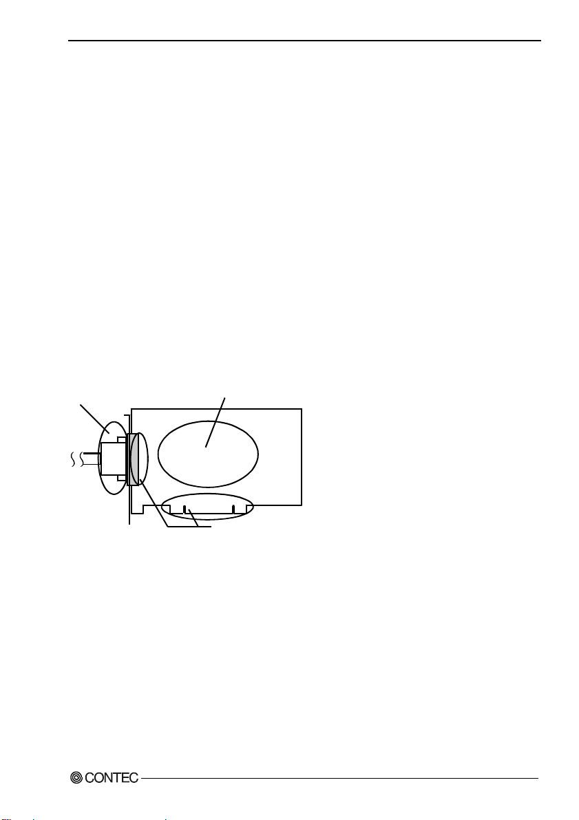
Inspect the product periodically as follows to use it safely.
- Check that the bus connector
of the board and its cable have
been plugged correctly.
- Check that the board has
no dust or foreign matter adhering.
- The gold-plated leads of the bus connector
have no stain or corrosion.
Storage
When storing this product, keep it in its original packing form.
(1) Put the board in the storage bag.
(2) Wrap it in the packing material, and then put it in the box.
(3) Store the package at room temperature at a place free from direct sunlight, moisture, shock,
vibration, magnetism, and static electricity.
Disposal
When disposing of the product, follow the disp osal procedures stipulated under the relevant laws and
municipal ordinances.
RRY-16C(PCI)H, RRY-32(PCI)H
7
Page 15

1. Before Using the Product
8
RRY-16C(PCI)H, RRY-32(PCI)H
Page 16

2. Setup
2. Setup
This chapter explains how to set up the board.
What is Setup?
Setup means a series of steps to take before the product can be used.
Different steps are required for software and hardware
The setup procedure varies with the OS and applications used.
Using the Board under Windows
Using the Driver Library API-PAC(W32)
This section describes the setup procedure to be performed before you can start developing application
programs for the board using the bund led C D -ROM “Driver Library API-PAC(W32)”.
Taking the following steps sets up the software and hardware. You can use the diagnosis program later
to check whether the software and hardware function normally.
Step 1 Installing the Software
Step 2 Setting the Hardware
Step 3 Installing the Hardware
Step 4 Initializing the Software
Step 5 Checking Operations with the Diagnosis Program
If Setup fails to be performed normally, see the “Setup Troubleshooting” section at the end of this
chapter.
Using the Board under Windows
Using Software Other than the Driver Library
API-PAC(W32)
For setting up software other than API-PAC(W32), refer to the user’s guide for that software. See also
the following parts of this user’s guide as required.
This chapter Step 2 Setting the Hardware
This chapter Step 3 Installing the Hardware
Chapter 3 External Connection
Chapter 6 About Hardware
RRY-16C(PCI)H, RRY-32(PCI)H
9
Page 17

2. Setup
Using the Board under an OS Other than Windows
For using the board under Linux, see the following parts of this guide.
This chapter Step 2 Se tting t he H ardw are
Chapter 3 External Connection
Chapter 5 About Software
Chapter 6 About Hardware
For using the board under an OS such as MS-DOS other than Windows, see the following parts of this
guide.
This chapter Step 2 Setting t he Hardware
Chapter 3 External Connection
Chapter 6 About Hardware
10
RRY-16C(PCI)H, RRY-32(PCI)H
Page 18

Step 1 Installing the Software
This section describes how to install the Driver libraries.
Before installing the hardware on your PC, install the Driver libraries from the bundled
API-PAC(W32) CD-ROM.
The following description assumes the operating system as Windows XP. Although some user
interfaces are different depending on the OS used, the basic procedure is the same.
Starting the Install Program
(1)
Load the CD-ROM [API-PAC(W32)] on your PC.
(2)
The API-PAC(W32) Installer window appears automatically.
If the panel does not appear, run (CD-ROM drive letter):\AUTORUN.exe.
(3)
Click on the [Install the drivers] button.
2. Setup
CAUTION
Before installing the software in Windows XP, 2000, or NT, you need to log in as a user with
administrator privileges.
RRY-16C(PCI)H, RRY-32(PCI)H
11
Page 19

2. Setup
Selecting the Digital I/O Driver
(1)
The following dialog box appears to select “Driver Type” and “Install Ty pe”.
(2)
Select “Digital I/O API-DIO(98/PC)NT”.
(3)
Select “Driver, Help, etc… (Full install)”.
(4)
Click on the [Install] button.
12
RRY-16C(PCI)H, RRY-32(PCI)H
Page 20

2. Setup
Executing the Installation
(1)
Follow the on-screen instructions to proceed to install.
(2) When the required files have been copied, the “Perform a hardware setup now” and “Show readme
file” check boxes are displayed.
When you are installing the software or hardw are for the first time:
1) Uncheck “Perform a hardware setup now”.
2) Click on the [Finish] button.
Go to Step 2 to set and plug the hardware.
*When the hardware has already been installed:
Check “Perform a hardware setup now” and then go to Step 4 “Initializing the Software”.
You have now finished installing the software.
RRY-16C(PCI)H, RRY-32(PCI)H
13
Page 21

2. Setup
Step 2 Setting the Hardware
This section describes how to set the board and plug it on your PC.
There are switches and jumpers on the board that need to be set in advance.
Be sure to check these before installing the board.
The board can be set up even with the factory defaults untouched. You can change board settings later.
Parts of the Board and Factory Defaults
Figure 2.1. or 2.2. shows the names of major parts on the board.
Note that the switch setting shown below is the factory default.
Parts name of board
RRY-16C(PCI)H
- Interface Connector
(CN1)
37
36 18
21 2
20
BOARD ID
SW1
- Board ID Setting SW
BOARD ID
9
7
A
6
B
5
C
4
D
3
E
2
F
1
0
SW1
19
1
Figure 2.1. Parts name of board < RRY-16C(PCI)H >
14
RRY-16C(PCI)H, RRY-32(PCI)H
Page 22

Parts name of board
2. Setup
- Interface Connector
(CN1)
37
36 18
21 2
20
RRY-32(PCI)H
19
1
BOARD ID
SW1
- Board ID Setting SW
BOARD ID
7
6
5
4
3
2
1
SW1
9
A
B
C
D
E
F
0
Figure 2.2. Parts name of board < RRY-32(PCI)H >
RRY-16C(PCI)H, RRY-32(PCI)H
15
Page 23

2. Setup
Setting the Board ID
If you install two or more boards on one personal computer, assign a different ID value to each of the
boards to distinguish them.
The board IDs can be set from 0 to Fh to identify up to sixteen boards.
If only one board is used, th e original factory setting (Board ID = 0) should be used.
Setting Procedure
To set the board ID, use the rotary switch on the boar d. Tur n the SW1 knob t o set the b oard ID as show n
below.
SW1
BOARD ID
9
A
7
B
6
5
C
D
4
3
E
Factory setting:
2
F
1
0
(Board ID= 0)
Figure 2.3. Board ID Settings (SW1)
16
RRY-16C(PCI)H, RRY-32(PCI)H
Page 24

2. Setup
Plugging the Board
(1) Before plugging the board, shut down the system, unplug the power cod e of you r PC.
(2) Remove the cover from the PC so that the board can be mounted.
(3) Plug the board into an expansion slot.
(4) Attach the board bracket to the PC with a screw.
(5) Put the cover back into place.
Applicable PCI bus slots
PCI bus slots used in PCs have keys to prevent 5V and 3.3V PCI bus boards from being accidentally
plugged into wrong bus slots. This board can be plugged into both of the 5V and 3.3V PCI bus slots.
<PCI bus slo t> <PCI bus bo ard>
5-V PCI bus slot
3.3-V PCI bus slot
3.3V key
CAUTION
5V key
A :
Slit for 5-V PCI bus slot
B :
Slit for 3.3-V PCI bus slot
AB
- Do not touch the board's metal plated terminals (edge co nnecto r) with your h ands.
Otherwise, the board may malfunction, overheat, or cause a failure.
If the terminals are touched by someone's hands, clean the terminals with industrial alcohol.
- Do not install or remove the board to or from the expansion slot while the PC or expansion unit
power is turned on.
Otherwise, the board may malfunction, overheat, or cause a failure.
Be sure that the PC power is turned off.
- Make sure that your PC or expansion unit can supply ample power to all the boards installed.
Insufficiently energized boards could malfunction, overheat, or cause a failure.
- Power supply from the PCI bus slot at +5V is required.
RRY-16C(PCI)H, RRY-32(PCI)H
17
Page 25

2. Setup
Step 3 Installing the Hardware
For using an expansion board un der Windows, you hav e to let the OS detect the I/O addre sses and IRQ to
be used by the board. The process is referred to as installing the hardware.
In the case of using two or more boards, make sure you install one by one with the Add New Hardware
Wizard.
Turning on the PC
Turn on the power to your PC.
CAUTION
- The board cannot be properly installed unless the resources (I/O addresses and interrupt level) for
the board can be allocated. Before attempting t o install the boar d, first determ ine what PC resources
are free to use.
- The resources used by each board do not depe nd on the location of the PCI bus slot or the board itself.
If you remove two or more boar ds that h ave alre ady b een in stalle d and the n rem ount one of them o n
the computer, it is unknown that which one of the sets of resources previously assigned to the two
boards is assigned to the remounted board. In this case, you must check the resource settings.
Setting with the Found New Hardware Wizard
(1) The “Found New Hardware Wizard” will be started.
Select “Install from a list or specific location (Advanced )”, then click on the [Next] button.
If you are using Windows NT 4.0, the “Found New Hardware Wizard” is not started.
Go to Step 4 “Initializing the Software”.
18
RRY-16C(PCI)H, RRY-32(PCI)H
Page 26

2. Setup
(2) Specify that folder on the CD-ROM which contains the setup information (INF) file to register the
board.
* The name of the board
you have just added is
displayed.
- RRY-16C(PCI)H
- RRY-32(PCI)H
Source folder
The setup information (INF) file is con t ai ned in the following folder on the bundle d CD-ROM.
Windows XP, 2000 \INF\Win2000\Dio\PCI
Windows Me, 98, 95 \INF\Win95\Dio\PCI
Example of specifying the folder for use under Windows XP
RRY-16C(PCI)H, RRY-32(PCI)H
\INF\Win2000\Dio\PCI
19
Page 27

2. Setup
CAUTION
In Windows XP, the Hardware Wizard disp lays the following alert dialog box when you have
located the INF file. This dialog box appears, only indi cating that the re levant dri ver has not passed
Windows Logo testing, and it ca n be ign ore d without developing any problem with the operation of
the board.
In this case, click on the [Continue Anyway] button.
You have now finished installing the software.
* The name of the board
you have just added is
displayed.
- RRY-16C(PCI)H
- RRY-32(PCI)H
20
RRY-16C(PCI)H, RRY-32(PCI)H
Page 28

2. Setup
Step 4 Initializing the Software
The API function library requires the initial setting to recognize the execution environment. It is called
the initialization of th e Dr iv er li b rary.
Invoking API-TOOL Configuration
(1) Open the Start Menu, then select “Programs” – “CONTEC API-PAC(W32)” – “API-TOOL
Configuration”.
(2) API-TOOL Configuration detects boards automatically.
The detected boards are listed.
Updating the Settings
(1) Select “Save settings to registry…” from the “File” menu.
You have now finished installing the initial setting of S o ftware.
RRY-16C(PCI)H, RRY-32(PCI)H
21
Page 29

2. Setup
Step 5 Checking Operations with the Diagnosis Program
Use the diagnosis program to check that the board and driver software work normally, thereby you can
confirm that they have been set up correctly.
What is the Diagnosis Program?
The diagnosis program diagnoses the states of the board and driver software.
It can also be used as a simple checker when an ex te rn al d ev ice i s ac tu al ly c on nec t ed.
Using the “Diagnosis Report” feature reports the driver settings, the presence or absence of the board,
I/O status, and interrupt status.
Check Method
Connect the board to a remote device to test the input/output or check the execution environment.
Please confirm that the board settings are the same as the factory settings.
To connect the board to external device, please refer to chapter 3 “External Connection”.
22
RRY-16C(PCI)H, RRY-32(PCI)H
Page 30

2. Setup
Using the Diagnosis Program
Starting the Diagnosis Program
Select the board in the API-TOOL Configuration windows, then run the Diagnosis Program . Follow the
instructions on screen.
* The name of the board you have just added is displayed.
* The name of the board
you have just added is
displayed.
- RRY-16C(PCI)H
- RRY-32(PCI)H
RRY-16C(PCI)H, RRY-32(PCI)H
23
Page 31

2. Setup
Checking Digital Inputs and Outputs
The main panel of the Diagnosis Program appears.
You can check the current operation states of the board in the following boxes:
“Input Port” : Displays input values bit by bit at fixed time interv als.
“Output Port” : Mouse operation allows the data to output or display.
“Interrupt” : Displays the number of interrupts detected bit by bit.
* The name of the board
you have just added is
displayed.
- RRY-16C(PCI)H
- RRY-32(PCI)H
To use the wait time control feature, click on the [Wait Configuration] button. Use the feature when the
wait time based on the DioWait or DioWaitEx function is not normal.
To use the function execution tim e measurement fea ture, click on the [Measurement Tim e] button. Ente r
the I/O start port and the number of ports, t hen press the measurement button. The time for each
execution of a function will be measured.
24
RRY-16C(PCI)H, RRY-32(PCI)H
Page 32

2. Setup
Diagnosis Report
(1) Clicking on the [Show Diagnosis Report] button displays detailed data such as board settings and
the diagnosis results while saving them in text format.
The results are saved and displayed as a text file (DioRep.txt) in the install folder (Program
Files\CONTEC\API-PAC(W32)).
The Diagnosis Program performs “board presence/absence che ck”, “driver file test”, “board setting
test”, and so on.
CAUTION
Before executing diagnosis report output, unplug the cable from the board.
(2) A diagnosis report is displayed as shown below.
* The name of the board
you have just added is
displayed.
- RRY-16C(PCI)H
- RRY-32(PCI)H
Click on [Show
Diagnosis Report].
* The name of the board
you have just added is
displayed.
- RRY-16C(PCI)H
- RRY-32(PCI)H
RRY-16C(PCI)H, RRY-32(PCI)H
25
Page 33

2. Setup
Setup Troubleshooting
Symptoms and Actions
The board cannot be initialized [Windows NT 4.0
The driver may not yet be activated.
When using the board under an OS not compliant with Plug and Play, such as Windows NT 4.0, make
sure that the [PnP OS] BIOS option has been set to [NO], [disable], or [Do not use]. If the option has
been set to [Windows 95], for example, the board may not be detected normally. For details on BIOS
settings, refer to the user’s guide for your PC.
No output can be obtained.
Use API-TOOL Configuration to check whether the board name setting is wrong.
The board works with the Diagnosis Program but not with an application.
The Diagnosis Program is coded with API-TOOL functions. As long as the board operates with the
Diagnosis Program, it is to operate with other applications as well. In such cases, review your program
while paying attention to the following points:
- Check the arguments to functions and their return valu es.
- When the board is an isolated type, it has a tim e lag for its response between the output by a functi on
and the actual output. Consider the execution intervals between functions.
The OS won’t normally get started or detect the board. [Windows XP
Turn off the power of your PC, then unplug the board. Restart the OS and delete the board settings of
API-TOOL Configuration. Turn off the PC again, plug the board, and restart the OS. Let the OS detect
the board and use API-TOOL Configuration to register board settings.
]
2000]
,
If your problem cannot be resolved
Contact your retailer.
26
RRY-16C(PCI)H, RRY-32(PCI)H
Page 34

3. External Connection
3. External Connection
This chapter describes the interface connector on the board and the external I/O circuits.
Check the information available here when connecting an external device.
Using the On-board Connectors
Connecting a Device to Connector
To connect an external device to the board, plug the cable from the device into the interface connecto r
shown below.
Connecting an Interface Connector and Connectors That Can Be Used
Interface connector (CN1)
- Connector used
37
36 18
21 2
20
37-pin D-SUB, female connector
19
DCLC-J37SAF-20L9(mfd. by JAE)
Thumb screw : UNC#4-40(inch screw)
- Applicable connectors
17JE-23370-02(D8C) (mfd. by DDK, Male)
1
FDCD-37P (mfd. by HIROSE, Male)
DC-37P-N (mfd. by JAE, Male)
CN1
Figure 3.1. Connecting an Interface Connector and Connectors That Can Be Used
< RRY-16C(PCI)H >
Connecting an Interface Connector and Connectors That Can Be Used
Interface connector (CN1)
- Connector used
37
36 18
21 2
20
37-pin D-SUB, female connector
19
DCLC-J37SAF-20L9(mfd. by JAE)
Thumb screw : UNC#4-40(inch screw)
- Applicable connectors
17JE-23370-02(D8C) (mfd. by DDK, Male)
FDCD-37P (mfd. by HIROSE, Male)
1
DC-37P-N (mfd. by JAE, Male)
CN1
Figure 3.2. Connecting an Interface Connector and Connectors That Can Be Used
< RRY-32(PCI)H >
RRY-16C(PCI)H, RRY-32(PCI)H
27
Page 35

3. External Connection
Connector Pin Assignment
Pin Assignments of RRY-16C(PCI)H Interface Connector
19
37
N.C.
36
Common of O- 17
Common of O- 16
Common of O- 15
Common of O- 14
Common of O- 13
Common of O- 12
Common of O-11
Common of O- 10
Common of O- 07
Common of O- 06
Common of O- 05
Common of O- 04
Common of O- 03
Common of O- 02
Common of O- 01
Common of O- 00
N 17
N 16
N 15
N 14
N 13
N 12
N 11
N 10
N 07
N 06
N 05
N 04
N 03
N 02
N 01
N 00
N.C.
35
34
33
32
31
30
29
28
27
26
25
24
23
22
21
20
Figure 3.3. Pin Assignments of RRY-16C(PCI)H Interface Connector
Pin Assignments of RRY-32(PCI)H Interface Connector
Common of +3 Port
+3 Output Port
+2 Output Port
Common of +2 Port
N3
O-37
O-36
O-35
O-34
O-33
O-32
O-31
O-30
O-27
O-26
O-25
O-24
O-23
O-22
O-21
O-20
N2
N.C.
18
N.C.
17
O-17
16
O-16
15
O-15
14
O-14
O-13
O-12
O-11
O-10
O-07
O-06
O-05
O-04
O-03
O-02
O-01
O-00
N.C.
N.C.
O-17
O-16
O-15
O-14
O-13
O-12
O-11
O-10
O-07
O-06
O-05
O-04
O-03
O-02
O-01
O-00
+1 Output Port
+0 Output Port
Common of +1 Port
N1
+1 Output Port
+0 Output Port
Common of +0 Port
N0
13
12
11
10
9
8
7
6
5
4
3
2
1
19
37
18
36
17
35
16
34
15
33
14
32
13
31
12
30
11
29
10
28
9
27
8
26
7
25
6
24
5
23
4
22
3
21
2
20
1
Figure 3.4. Pin Assignments of RRY-32(PCI)H Interface Connector
28
RRY-16C(PCI)H, RRY-32(PCI)H
Page 36

3. External Connection
Relationships between API-PAC(W32) Logical Ports/Bits and
Connector Signal Pins
The following table lists the relationships between the connector signal pins and the logical port/bit
numbers used for I/O functions when applications are written with API-PAC(W32).
RRY-16C(PCI)H
Table 3.1. Logical P or ts, Log ica l Bi ts , a nd C on ne cto r Sig na l Pin s < RRY-16C(PCI)H >
D7 D6 D5 D4 D3 D2 D1 D0
O-07
O-06
O-05
O-04
O-03
O-02
O-01
Output logical port 0
Output logical port 1
Note: O-xx represents output signals, respectively, where [xx] indicates a l ogical bit.
[7]
O-17
[15]
[6]
O-16
[14]
[5]
O-15
[13]
[4]
O-14
[12]
[3]
O-13
[11]
[2]
O-12
[10]
RRY-32(PCI)H
Table 3.2. Logical Ports, Logical Bits, and Connector Signal Pins < RRY-32(PCI)H >
D7 D6 D5 D4 D3 D2 D1 D0
O-07
O-06
O-05
O-04
O-03
Output logical port 0
Output logical port 1
Output logical port 2
Output logical port 3
Note: O-xx represents output signals, respectively, where [xx] indicates a l ogical bit.
[7]
O-17
[15]
O-27
[23]
O-37
[31]
[6]
O-16
[14]
O-26
[22]
O-36
[30]
[5]
O-15
[13]
O-25
[21]
O-35
[29]
[4]
O-14
[12]
O-24
[20]
O-34
[28]
[3]
O-13
[11]
O-23
[19]
O-33
[27]
O-02
[2]
O-12
[10]
O-22
[18]
O-32
[26]
[1]
O-11
[9]
O-01
[1]
O-11
[9]
O-21
[17]
O-31
[25]
O-00
[0]
O-10
[8]
O-00
[0]
O-10
[8]
O-20
[16]
O-30
[24]
CAUTION
The logical port and logical bit numbers are virtual port and bit numbers that enable programming
independent of board I/O addresses or board types.
For details, refer to API-DIO HELP available after installing API-PAC(W32).
RRY-16C(PCI)H, RRY-32(PCI)H
29
Page 37

3. External Connection
Output Signal Connection
Figure 3.5 and figure 3.6 shows the outp ut circ uit at the interface se ctio n of the boar d. The signal outpu t
section uses a relay contact method to send signals to the external device.
Output Circuit
RRY-16C(PCI)H
Load
External Side
External
Power Supply
Board Side
Output pin
Common
Relay
* Output pin represents O-xx.
Figure 3.5. Output Circuit < RRY-16C(PCI)H >
RRY-32(PCI)H
External SideBoard Side
Relay
* Output pin represents O-xx.
Figure 3.6. Output Circuit <
CAUTION
Output pin
Common
RRY-32(PCI)H
Load
>
External
Power Supply
When the PC is turned on, al l outpu ts ar e res et to O FF .
30
RRY-16C(PCI)H, RRY-32(PCI)H
Page 38

Connection to the LED
RRY-16C(PCI)H
LED
LED
1.2kΩ
1.2kΩ
+
External
Power Supply
5VDC
-
+
External
Power Supply
5VDC
-
O-00 (CN1: Pin 2)
Board side
Common of O-00 (CN1: Pin 21)
Output a "1" to a bit will light the LED that is connected to the related relay output.
On the other hand, output a "0" to the bit will switch the LED off.
Figure 3.7. An Example to use Output O-00 < RRY-16C(PCI)H >
RRY-32(PCI)H
O-00 (CN1: Pin 2)
Board side
Common of +0 Port (CN1: Pin 1)
Output a "1" to a bit will light the LED that is connected to the related relay output.
On the other hand, output a "0" to the bit will switch the LED off.
3. External Connection
Figure 3.8. An Example to use Output O-00 < RRY-32(PCI)H >
RRY-16C(PCI)H, RRY-32(PCI)H
31
Page 39

3. External Connection
32
RRY-16C(PCI)H, RRY-32(PCI)H
Page 40

4. Function
4. Function
This section describes the features of the board.
Data I/O Function
Data Output
Providing “1” output to the correspond ing bit makes the relay contact turned ON (make state).
Providing, in turn, “0” output to the correspon ding bit makes the relay contact turned OFF (break state).
The state of the output data is kept intact until th e output instruction is executed again.
CAUTION
When the PC is turned on, a ll ou tputs a re re se t to 0 (OFF).
Monitoring Output Data
The board can read the state of the data currently being output without affecting the output data.
RRY-16C(PCI)H, RRY-32(PCI)H
33
Page 41

4. Function
34
RRY-16C(PCI)H, RRY-32(PCI)H
Page 42

5. About Software
CD-ROM Directory Structure
\
|– Autorun.exe Installer Main Window
| Readmej.html Version information on each API-TOOL (Japanese)
| Readmeu.html Version information on each API-TOOL (English)
.
.
|–––APIPAC E ach inst al ler
| |––AIO
| | |––DISK1
| | |––DISK2
| | |––……
| | |––DISKN
| |––AioWdm
| |––CNT
| |––DIO
| |––……
.
.
| ––HELP HELP file
| |––Aio
| |––Cnt
| |––……
.
.
| ––INF Each INF file for OS
| |––WDM
| |––Win2000
| |––Win95
.
.
|––linux Linux driver file
| |––cnt
| |––dio
| |––……
.
.
| ––Readme Readme file for each driver
.
.
| ––Release Driver file on each API-TOOL
| |––API_NT (For creation of a user-specific install program)
| |––API_W95
.
.
| ––UsersGuide Hardware User's Guide(PDF files)
5. About Software
RRY-16C(PCI)H, RRY-32(PCI)H
35
Page 43

5. About Software
About Software for Windows
The bundled CD-ROM “Driver Library API-PAC(W32)” contains the functions th at provide the
following features:
- Digital input/output of specified ports
- Hardware digital input/output of specified bits
For details, refer to the help file. The help file provides various items of information such as “Function
Reference”, “Sample Programs”, and “FAQs”. Use them for program development and troublesh ooting.
Accessing the Help File
(1) Click on the [Start] button on the Windows taskbar.
(2) From the Start Menu, select “Programs” – “CONTEC API-PAC(W32)” – “Dio” – “API-DIO
HELP” to display help information.
36
RRY-16C(PCI)H, RRY-32(PCI)H
Page 44

5. About Software
Using Sample Programs
Sample programs have been prepared for specific basic applications.
To use each sample program, enter its driver number and grou p number set by API-T OOL Configurati on
in the DrvNo and GrpNo fields.
Use these sample programs as references for program development and operation check.
The sample programs are stored in \Program Files\CONTEC\API-PAC(W32)\Dio\Samples.
Running a Sample Program
(1) Click on the [Start] button on the Windows taskbar.
(2) From the Start Menu, select “Programs” – “CONTEC API-PAC(W32)” – “Dio” – “SAMPLE…”.
(3) A sample program is invoked.
RRY-16C(PCI)H, RRY-32(PCI)H
37
Page 45

5. About Software
Sample Programs - Examples
-Sample program 1 : Inputs digital data through a specified port.
-Sample program 2 : Outputs digital data through a specified port.
-Sample program 3 : Inputs/outputs digital data from/to a programmable board.
-Sample program 4 : Inputs digital data from a specified port in the background.
-Sample program 5 : Inputs/outputs digital data from/to a specified bit.
-Sample program 6 : Services interrupts of a specified board.
-Sample program 7 : Provides process control of a specified board.
-Sample program 8 : Performs trigger monitoring of a specified board.
-Sample program 9 : Inputs digital data through a specified port using BCD data.
-Sample program 10 : Executes digital input (simple functions) at specified bits through a
-Sample program 11 : Services interrupts of a specified board (using an extended function).
-Sample program (Console): Inputs/outputs digital data through a specified board.
[Sample program 1] [Sample program 2]
specified port.
[Sample program 5] [Sample program 9]
38
RRY-16C(PCI)H, RRY-32(PCI)H
Page 46

5. About Software
Uninstalling the Driver Libraries
To uninstall API-PAC(W32), follow the procedure below.
(1) Click on the [Start] button on the Windows taskbar. From the Start Menu, select “Control Panel”.
(2) Double-click on “Add/Remove Programs” in the Control Panel.
(3) Select “CONTEC API-DIO(98/PC)xx” from the application list displayed, then click on the
[Change/Remove] button. Follow the on-screen instructions to uninstall the function libraries.
RRY-16C(PCI)H, RRY-32(PCI)H
39
Page 47

5. About Software
About Software for Linux
The Linux version of digital I/O function driver, API-DIO(LNX), provides functions that execute the
following features:
- Digital input/output of specified ports
- Digit a l input/output of spe c ified bits
For details, refer to the help file. The help file provides various items of information such as “Function
Reference”, “Sample Programs”, and “FAQs”. Use them for program development and troublesh ooting.
Driver Software Install Procedure
The Linux version for digital I/O driver, API-DIO(LNX), is supplied as a compressed file
/linux/dio/cdioXXX.tgz on the bundled API-PAC(W32)CD-ROM. (Note: XXX represents the driver
version.)
Mount the CD-ROM as shown below, copy the file to an arbitrary directory, and decomp ress the file to
install the driver.
For details on using the driver, refer to readme.txt and the help file in HTML format extracted by
installation.
To install the driver, l og in as a sup erus er.
Decompression and setup procedure
# cd
# mount /dev/cdrom /mnt/cdrom Mount the CD-ROM.
# cp /mnt/cdrom/linux/dio/cdioXXX.tgz ./ Copy the compressed file.
# tar xvfz cdioXXX.tgz Decompress the compressed file.
................
# cd contec/cdio
# make
Compile the file.
................
# make install Install.
................
# cd config
# ./config Set up the board to be used.
..... Set as follows.........
# ./contec_dio_start.sh Start the driver.
# cd
40
RRY-16C(PCI)H, RRY-32(PCI)H
Page 48

5. About Software
Accessing the Help File
(1) Invoke a web browser in your X-Window environment.
(2) In the browser, open diohelp.htm in the contec/cdio/help directory.
Using Sample Programs
Sample programs have been prepared for specific basic applications.
Sample programs for each language are contained in the contec/cdio/samples directory. For compiling
them, refer to the manual for the desired language.
Uninstalling the driver
To uninstall the driver, use the uninstall shell script contained in the contec/cdio directory. For details,
check the contents of the script.
RRY-16C(PCI)H, RRY-32(PCI)H
41
Page 49

5. About Software
42
RRY-16C(PCI)H, RRY-32(PCI)H
Page 50

6. About Hardware
6. About Hardware
This chapter provides hardware specifications and hardware-related supplementary information.
Hardware specification
RRY-16C(PCI)H
Table 6.1. Specification < RRY-16C(PCI)H >
Items Specificatio ns
No. of Output Channels 16 channels
Output Format Reed Relay (1a, make) Ou tput
Relay Contact
Spec.
I/O Addresses 8 bits x 32 ports boundary
Max. board count in One System 16 boards including this board
Power Consumption 5 VDC 550mA (Max.)
Operating Condition 0 - 50°C, 10 - 90%RH (No condensa tion)
PCI Bus Specification 32bit, 33MHz, Universal key shapes supported *1
Dimension(mm) 121.69(L) x 105.68(H)
Weight 150g
*1
This board requires +5V power supply from expansion slots (it does not operate in the environment of only +3.3V
power supply).
Board Dimensions
Max. Operating Voltage 125V (AC), 30V (DC)
Max. Carry Current 2A (Max.)
Contact resistance (Initial state) 30mΩ or less
Operating time
(At the time of ON)
Recovery time
(At the time of OFF)
Mechanical Life Expectancy
Electrical lifetime
Relay Type PCN-105D3MHZ
121.69(L)
Within 7ms
Within 6ms
20,000,000 operations min or more
Switching times : 180/min
100,000 operations min or more
Switching times : 20/min
105.68(H)
[mm]
The standard outside dimension (L) is
the distance from the end of the board
to the outer surface of the slot cover.
RRY-16C(PCI)H, RRY-32(PCI)H
43
Page 51

6. About Hardware
RRY-32(PCI)H
Table 6.2. Specification < RRY-32(PCI)H >
Items Specificatio ns
No. of Output Channels 32 channels
Output Format Reed Relay (1a, make) Output
Relay Contact
Spec.
I/O Address 8 bits x 32 ports boundary
Max. board count in One System 16 boards including this board
Power Consumption 5 VDC 1050mA (Max.)
Operating Condition 0 - 50°C, 10 - 90%RH (No condensation)
PCI Bus Specification 32bit, 33MHz, Universal key shapes supported *1
Dimension(mm) 176.41(L) x 105.68(H)
Weight 150g
*1
This board requires +5V power supply from expansion slots (it does not operate in the environment of only +3.3V
power supply).
Max. Operating Power 10VA(AC), 10W(DC)
Max. Operating Voltage 100V(AC), 100V(DC)
Max. Carry Current 0.5A(Max.)
Contact resistance 100mΩ or less
Response Time Within 1ms
Mechanical Life Expectancy 200,000,000 operations min or more
Relay Type MSG-105AK1 (or equivalent to it)
Board Dimensions
176.41(L)
105.68(H)
[mm]
The standard outside dimension (L) is
the distance from the end of the board to
the outer surface of the slot cover.
44
RRY-16C(PCI)H, RRY-32(PCI)H
Page 52

Block Diagram
RRY-16C(PCI)H
6. About Hardware
Driver
Control
PCI bus
circuit
Driver
Reed
Relay
Reed
Relay
RRY-16C(PCI)H
Figure 6.1. Block Diagram < RRY-16C(PCI)H >
Output port 0
Output port 1
RRY-16C(PCI)H, RRY-32(PCI)H
45
Page 53

6. About Hardware
RRY-32(PCI)H
Driver
Driver
Control
PCI bus
circuit
Driver
Driver
Reed
Relay
Reed
Relay
Reed
Relay
Reed
Relay
RRY-32(PCI)H
Figure 6.2. Block Diagram < RRY-32(PCI)H >
Output port 0
Output port 1
Output port 2
Output port 3
46
RRY-16C(PCI)H, RRY-32(PCI)H
Page 54

6. About Hardware
Difference from RRY-16C(PCI) and RRY-32(PCI)
RRY-16C(PCI)H and RRY-32(PCI)H are partially enhanced version of the conventional products of
RRY-16C(PCI) and RRY-32(PCI) and they are upper compatible with RRY-16C(PC I) and
RRY-32(PCI).
So you can use the same operating procedures as RRY-16C(PCI) and RRY-32(PCI).
There are some differences in specifications as shown below.
Table 6.3. Difference of specifications
RRY-16C(PCI)H
RRY-16C(PCI) RRY-16C(PCI)H
I/O address 8 bits x 4 ports b ounda ry 8 bits x 32 ports boundary
Power consumption 5VDC 700mA (Max.) 5VDC 550mA (Max.)
PCI bus specification 32bit, 33MHz, 5V
Dimension (mm) 121.69(L) x 106.68(H) 121.69(L) x 105.68(H)
RRY-32(PCI)H
RRY-32(PCI) RRY-32(PCI)H
I/O address 8 bits x 4 ports b ounda ry 8 bits x 32 ports bounda ry
Power consumption 5VDC 1200mA (Max.) 5VDC 1050mA (Max.)
PCI bus specification 32bit, 33MHz, 5V
Dimension (mm) 176.41(L) x 106.6 8(H) 176.41(L) x 105.68(H)
32bit, 33MHz, Universal key shapes supported
(Supply 5V to the 5V pin)
32bit, 33MHz, Universal key shapes supported
(Supply 5V to the 5V pin)
RRY-16C(PCI)H, RRY-32(PCI)H
47
Page 55

RRY-16C(PCI)H
RRY-32(PCI)H
User’s Guide
CONTEC CO., LTD. February 2005 Edition
3-9-31, Himesato, Nishiyodogawa-ku, Osaka 555-0025, Japan
Japanese http://www.contec.co.jp/
English http://www.contec.com/
Chinese http://www.contec.com.cn/
No part of this document may be copied or reproduced in any form by any means without prior written
consent of CONTEC CO., LTD. [02032005]
[02032005] Management No. A-51-008
Parts No. LYES141
 Loading...